EP4065871B1 - Dichtung mit unterschiedlichen verdichtungen - Google Patents
Dichtung mit unterschiedlichen verdichtungen Download PDFInfo
- Publication number
- EP4065871B1 EP4065871B1 EP20821438.7A EP20821438A EP4065871B1 EP 4065871 B1 EP4065871 B1 EP 4065871B1 EP 20821438 A EP20821438 A EP 20821438A EP 4065871 B1 EP4065871 B1 EP 4065871B1
- Authority
- EP
- European Patent Office
- Prior art keywords
- fitting
- seal
- thread
- screw
- screws
- Prior art date
- Legal status (The legal status is an assumption and is not a legal conclusion. Google has not performed a legal analysis and makes no representation as to the accuracy of the status listed.)
- Active
Links
Images

Classifications
-
- F—MECHANICAL ENGINEERING; LIGHTING; HEATING; WEAPONS; BLASTING
- F16—ENGINEERING ELEMENTS AND UNITS; GENERAL MEASURES FOR PRODUCING AND MAINTAINING EFFECTIVE FUNCTIONING OF MACHINES OR INSTALLATIONS; THERMAL INSULATION IN GENERAL
- F16L—PIPES; JOINTS OR FITTINGS FOR PIPES; SUPPORTS FOR PIPES, CABLES OR PROTECTIVE TUBING; MEANS FOR THERMAL INSULATION IN GENERAL
- F16L5/00—Devices for use where pipes, cables or protective tubing pass through walls or partitions
- F16L5/02—Sealing
- F16L5/08—Sealing by means of axial screws compressing a ring or sleeve
-
- F—MECHANICAL ENGINEERING; LIGHTING; HEATING; WEAPONS; BLASTING
- F16—ENGINEERING ELEMENTS AND UNITS; GENERAL MEASURES FOR PRODUCING AND MAINTAINING EFFECTIVE FUNCTIONING OF MACHINES OR INSTALLATIONS; THERMAL INSULATION IN GENERAL
- F16J—PISTONS; CYLINDERS; SEALINGS
- F16J15/00—Sealings
- F16J15/16—Sealings between relatively-moving surfaces
- F16J15/32—Sealings between relatively-moving surfaces with elastic sealings, e.g. O-rings
- F16J15/3284—Sealings between relatively-moving surfaces with elastic sealings, e.g. O-rings characterised by their structure; Selection of materials
-
- A—HUMAN NECESSITIES
- A62—LIFE-SAVING; FIRE-FIGHTING
- A62C—FIRE-FIGHTING
- A62C2/00—Fire prevention or containment
- A62C2/06—Physical fire-barriers
- A62C2/065—Physical fire-barriers having as the main closure device materials, whose characteristics undergo an irreversible change under high temperatures, e.g. intumescent
-
- F—MECHANICAL ENGINEERING; LIGHTING; HEATING; WEAPONS; BLASTING
- F16—ENGINEERING ELEMENTS AND UNITS; GENERAL MEASURES FOR PRODUCING AND MAINTAINING EFFECTIVE FUNCTIONING OF MACHINES OR INSTALLATIONS; THERMAL INSULATION IN GENERAL
- F16L—PIPES; JOINTS OR FITTINGS FOR PIPES; SUPPORTS FOR PIPES, CABLES OR PROTECTIVE TUBING; MEANS FOR THERMAL INSULATION IN GENERAL
- F16L3/00—Supports for pipes, cables or protective tubing, e.g. hangers, holders, clamps, cleats, clips, brackets
- F16L3/08—Supports for pipes, cables or protective tubing, e.g. hangers, holders, clamps, cleats, clips, brackets substantially surrounding the pipe, cable or protective tubing
- F16L3/10—Supports for pipes, cables or protective tubing, e.g. hangers, holders, clamps, cleats, clips, brackets substantially surrounding the pipe, cable or protective tubing divided, i.e. with two members engaging the pipe, cable or protective tubing
-
- F—MECHANICAL ENGINEERING; LIGHTING; HEATING; WEAPONS; BLASTING
- F16—ENGINEERING ELEMENTS AND UNITS; GENERAL MEASURES FOR PRODUCING AND MAINTAINING EFFECTIVE FUNCTIONING OF MACHINES OR INSTALLATIONS; THERMAL INSULATION IN GENERAL
- F16L—PIPES; JOINTS OR FITTINGS FOR PIPES; SUPPORTS FOR PIPES, CABLES OR PROTECTIVE TUBING; MEANS FOR THERMAL INSULATION IN GENERAL
- F16L5/00—Devices for use where pipes, cables or protective tubing pass through walls or partitions
- F16L5/02—Sealing
- F16L5/04—Sealing to form a firebreak device
-
- H—ELECTRICITY
- H02—GENERATION; CONVERSION OR DISTRIBUTION OF ELECTRIC POWER
- H02G—INSTALLATION OF ELECTRIC CABLES OR LINES, OR OF COMBINED OPTICAL AND ELECTRIC CABLES OR LINES
- H02G3/00—Installations of electric cables or lines or protective tubing therefor in or on buildings, equivalent structures or vehicles
- H02G3/22—Installations of cables or lines through walls, floors or ceilings, e.g. into buildings
-
- A—HUMAN NECESSITIES
- A62—LIFE-SAVING; FIRE-FIGHTING
- A62C—FIRE-FIGHTING
- A62C3/00—Fire prevention, containment or extinguishing specially adapted for particular objects or places
- A62C3/16—Fire prevention, containment or extinguishing specially adapted for particular objects or places in electrical installations, e.g. cableways
Definitions
- the present invention concerns a seal with different compressions.
- the seal has parts of different material, which different parts are to be compressed with different forces.
- a cylindrical seal for sealing a cable or pipe going through an opening of some kind of partition.
- a cylindrical seal may comprise a compressible part and fittings at opposite ends of the compressible part.
- the seal is placed around the cable or pipe inside the opening of the partition, where after the compressible part is compressed by the fittings being moved towards each other by means of screws.
- the compressible part As the compressible part is compressed in axial direction, it expands in radial direction both inwards and outwards, to seal inwards against the cable or pipe and outwards against the opening of the partition.
- Seals of this kind are normally placed directly in an opening in the partition or in a sleeve received in the opening of the partition.
- the partition could be a deck or bulkhead of a ship, a wall of a cabinet, a technical shelter, a junction box or a machine, or a wall, floor or roof of a building.
- sealing material having different properties. It can for example be a need for sealing against water pressure and fire at the same transition. Other properties may also be wanted, resulting in materials having different properties. However, such materials may have large differences in mechanical properties. For example, a very porous material together with a high density material. Thus, to function optimally the different sealing materials may need and/or withstand different compressing forces.
- US 2010/219589 A1 discloses a seal for pipe penetration formed of two halves, the seal received in a sleeve or opening of a wall.
- one object of the present invention is to provide a seal wherein different sealing materials having different properties may be compressed irrespectively of each other. It could also be expressed as a possibility to combine materials with different properties in one single product with controlled compression (for example 30° Shore A in combination with 90° Shore A).
- a seal is formed of two identical seal halves.
- Each seal half comprises a front fitting, a rear fitting, a compressible part placed between the front fitting and the rear fitting and a number of screws going through openings in the front fitting, the rear fitting and the compressible part.
- the compressible part comprises a first material, a second material and a middle fitting placed between first material and the second material.
- the first material, the second material and the middle fitting have through openings for receiving the screws, wherein the seal has means to move the rear fitting and the middle fitting different axial lengths in relation to the front fitting when manipulating said means and that the first material and the second material have different properties.
- Means may be arranged to be able to compress the first and second materials independently of each other.
- said means is screws acting on the rear fitting, which screws are surrounded by sockets acting on the middle fitting.
- said means are screws having threads of different pitches acting on the rear fitting and the middle fitting, respectively.
- a seal half 1 comprising a first material 2 and a second material 3, which first and second materials 2, 3 are made of compressible materials, such as rubber.
- a front fitting 4 is placed on an outer side of the second material 3 and a rear fitting 5 is placed at an outer side of the first material 2.
- the front fitting 4 and the rear fitting 5 are placed at opposite ends of the seal half 1.
- a middle fitting 6 is placed between the first material 2 and the second material 3. The first material 2 and the second material 3 form a compressible part of the seal half 1 together with the middle fitting 6.
- a number of screws 7 goes through openings in the front fitting 4, the second material 3, the middle fitting 6 and the first material 2 and ends in threaded openings in the rear fitting 5.
- Each screw 7 has a screw head 8, in the form of a socket head cap, received at an outer side of the front fitting 4 and a thread 9 for co-operation with one of the threaded openings of the rear fitting 5.
- a socket 10 is placed outside a stem of each screw 7 between the front fitting 4 and the middle fitting 6.
- Each socket 10 has a socket head 11, which is hexagonal in the shown embodiment, and which socket head 11 is placed outside and surrounding the screw head 8.
- Each socket 10 goes through an opening in the front fitting 4 and has a thread 12 at an end which is received in a threaded opening of the middle fitting 6.
- Each screw 7 and the socket 10 placed outside said screw 7 are free to rotate in relation to each other.
- a cylindrical seal is formed in that two seal halves 1 are placed against each other on opposite sides of a cable or pipe.
- An outer diameter of the front fittings 4 of the formed seal is larger than an inner diameter of an opening of partition, in which opening the cable or pipe with attached seal is to be received, wherein the seal is stopped from going through the opening in the partition.
- the outer diameter of the front fittings are the same as for the middle fittings and the rear fittings. Such embodiments are used when the seal is to be placed a distance into an opening, a pipe or a sleeve.
- the rear fitting 5 By rotating of the screws 7 of the seal half 1, the rear fitting 5 is moved in a direction towards or away from the front fitting 4. The position of the middle fitting 6 is not changed by rotating of the screws 7.
- the middle fitting 6 By rotating of the sockets 10, the middle fitting 6 is moved in a direction towards or away from the front fitting 4. The position of the rear fitting 5 is not changed by rotating of the sockets 10.
- the lengths the rear fitting 5 and the middle fitting 6 are to be moved in relation to the front fitting 4 depends on the ability of the first material 2 and the second material 3, respectively, to withstand axial compression and the axial compression needed to give the desired function.
- the seal half 1 has a number of layers 13 on the inside of the first and second materials 2, 3.
- a number of said layers 13 may be peeled off to adapt an inner diameter of a seal formed of two seal halves 1 to an outer diameter of a cable or pipe to be received inside such a formed seal.
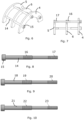
- each screw 7 and corresponding socket 10 is replaced with one single screw 14.
- Each of the single screws 14 has a screw head 15, which is in the form of a socket head cap in the shown embodiment, and which screw head 15 is received on the outside of the front fitting 4.
- the screw 14 has a first thread 16 to mesh with one of the threaded openings of the middle fitting 6 and a second thread 17 to mesh with one of the threaded openings of the rear fitting 5.
- the rear fitting 5 and the middle fitting 6 may move different distances in relation to the front fitting 4 when the screw 14 is manipulated.
- the screw 14 of Fig. 8 the first thread 16 has a pitch of 0.5mm and the second thread 17 has a pitch of 1mm, which will give a ratio of 1:2 for the movement of the middle fitting 6 in respect of the rear fitting 5, when the screw 14 is manipulated.
- the first material 2 will be compressed more than the second material 3 when the screws 12 are tightened.
- a screw 18 is shown having a first thread 19 with a pitch of 1mm and a second thread 20 with a pitch of 0.5mm, giving a ratio of 2:1 for the movement of the middle fitting 6 in respect to the rear fitting 5, when the screw 18 is manipulated.
- the first material 2 will be compressed less that the second material 3 when the screws 18 are tightened.
- a screw 21 is shown having a first thread 22 with a pitch of 0.5mm and a second thread 23 with a pitch of 0.8mm, giving a ratio of 1:1.6 for the movement of the middle fitting 6 in respect of the rear fitting 5, when the screw 21 is manipulated.
- the first material 2 will be compressed more than the second material 3 when the screws 21 are tightened.
- the pitch of the thread of the openings of the middle fitting 6 and the rear fitting 5, respectively, are adapted to the pitches of the first and second threads 16, 17, 19, 20, 22, 23, respectively, of the screws 14, 18, 21 used.
- screws having first and second threads with other pitches than as indicated above may be chosen depending of the properties and axial length of the first material 2 and the second material 3, respectively.
- two seal halves 1 are placed opposite each other surrounding a cable or pipe going through an opening of a partition.
- one or more layers 13 may be peeled off from each seal half 1.
- the seal is then pushed into the opening of the partition, with the rear fitting 5 first, until the front fitting 4 abuts the partition, if the outer diameter of the front fitting 4 is larger than the inner diameter of the opening of the partition.
- the seal may be pushed further into the opening of the partition.
- the screws and possible sockets are then tightened to compress the first and second materials 2, 3 independently of each other. By the axial compression each of the first and second materials 2, 3 will expand radially to seal against the cable or pipe and the opening of the partition. By said radial expansion the seal will also be held in the opening of the partition.
Landscapes
- Engineering & Computer Science (AREA)
- General Engineering & Computer Science (AREA)
- Mechanical Engineering (AREA)
- Architecture (AREA)
- Civil Engineering (AREA)
- Structural Engineering (AREA)
- Health & Medical Sciences (AREA)
- Public Health (AREA)
- Business, Economics & Management (AREA)
- Emergency Management (AREA)
- Installation Of Indoor Wiring (AREA)
- Laying Of Electric Cables Or Lines Outside (AREA)
- Gasket Seals (AREA)
- Quick-Acting Or Multi-Walled Pipe Joints (AREA)
Claims (10)
- Dichtung, gebildet aus zwei identischen Dichtungshälften (1), wobei jede Dichtungshälfte (1) eine vordere Befestigung (4), eine hintere Befestigung (5), einen komprimierbaren Teil, der zwischen der vorderen Befestigung (4) und der hinteren Befestigung (5) angeordnet ist, und eine Anzahl von Schrauben (7, 14, 18, 21), die durch Öffnungen in der vorderen Befestigung (4), der hinteren Befestigung (5) und dem komprimierbaren Teil gehen, umfasst,wobei der komprimierbare Teil ein erstes Material (2), ein zweites Material (3) und eine mittlere Befestigung (6) aufweist, die zwischen dem ersten Material (2) und dem zweiten Material (3) angeordnet ist, und wobei das erste Material (2), das zweite Material (3) und die mittlere Befestigung (6) durchgehende Öffnungen zur Aufnahme der Schrauben (7, 14, 18, 21) aufweisen,dadurch gekennzeichnet, dass die Dichtung ein Mittel aufweist, um die hintere Befestigung (5) und die mittlere Befestigung (6) axial um unterschiedliche Längen in Bezug auf die vordere Befestigung (4) zu bewegen, wenn dieses Mittel betätigt wird, und dass das erste Material (2) und das zweite Material unterschiedliche Eigenschaften haben.
- Dichtung nach Anspruch 1, wobei eines der ersten und zweiten Materialien (2, 3) eine hauptsächlich vor Feuer schützende Eigenschaft hat, zum Beispiel ein intumeszierendes Material ist, und wobei eines der ersten und zweiten Materialien (2, 3) eine hauptsächlich abdichtende Eigenschaft hat.
- Dichtung nach Anspruch 1 oder 2, wobei das Mittel zum Bewegen der hinteren Befestigung (5) und der mittleren Befestigung (6) um unterschiedliche axiale Längen Schrauben (7) umfasst, die von Buchsen (10) umgeben sind.
- Dichtung nach Anspruch 3, wobei jede Schraube (7) ein Gewinde (9) zum Zusammenwirken mit einem Gewinde einer der Öffnungen der hinteren Befestigung (5) aufweist, wobei jede Buchse (10) ein Außengewinde (12) für das Zusammenwirken mit einem Gewinde einer der Öffnungen der mittleren Befestigung (6) aufweist und wobei die Schraube (7) und die Buchse (8) unabhängig voneinander gedreht werden können.
- Dichtung nach Anspruch 3 oder 4, wobei ein Schraubenkopf (8) der Schraube (7) in einem Buchsenkopf (11) der Buchse (10) aufgenommen ist.
- Dichtung nach Anspruch 1 oder 2, bei der das Mittel zum Bewegen der hinteren Befestigung (5) und der mittlere Befestigung (6) um unterschiedliche axiale Längen Schrauben (14, 18, 21) mit einem ersten Gewinde (16, 19, 22) und einem zweiten Gewinde (17, 20, 23) aufweist und wobei das erste Gewinde (16, 19, 22) und das zweite Gewinde (17, 20, 23) jeder Schraube (14, 18, 21) unterschiedliche Steigungen aufweisen.
- Dichtung nach Anspruch 6, wobei das erste Gewinde (16, 19, 22) jeder Schraube (14, 18, 21) mit einem Gewinde einer der Öffnungen der mittleren Befestigung (6) zusammenwirken soll und das zweite Gewinde (17, 20, 23) jeder Schraube (14, 18, 21) mit einem Gewinde einer der einer der Öffnungen der hinteren Befestigung (5) zusammenwirken soll.
- Dichtung nach Anspruch 6 oder 7, wobei das erste Gewinde (16, 22) einer jeden Schraube (14, 21) eine geringere Steigung aufweist als das zweite Gewinde (17, 23).
- Dichtung nach Anspruch 6 oder 7, wobei das erste Gewinde (19) einer jeden Schraube (18) eine größere Steigung hat als das zweite Gewinde (20).
- Dichtung nach einem der vorhergehenden Ansprüche, wobei eine Anzahl von abziehbaren Schichten (13) auf der Innenseite des ersten und zweiten Materials (2, 3) angeordnet sind.
Applications Claiming Priority (2)
| Application Number | Priority Date | Filing Date | Title |
|---|---|---|---|
| SE1951350A SE543754C2 (en) | 2019-11-26 | 2019-11-26 | Seal with different compressions |
| PCT/SE2020/051118 WO2021107841A1 (en) | 2019-11-26 | 2020-11-24 | Seal with different compressions |
Publications (3)
| Publication Number | Publication Date |
|---|---|
| EP4065871A1 EP4065871A1 (de) | 2022-10-05 |
| EP4065871B1 true EP4065871B1 (de) | 2024-08-07 |
| EP4065871C0 EP4065871C0 (de) | 2024-08-07 |
Family
ID=73790182
Family Applications (1)
| Application Number | Title | Priority Date | Filing Date |
|---|---|---|---|
| EP20821438.7A Active EP4065871B1 (de) | 2019-11-26 | 2020-11-24 | Dichtung mit unterschiedlichen verdichtungen |
Country Status (6)
| Country | Link |
|---|---|
| US (1) | US11898639B2 (de) |
| EP (1) | EP4065871B1 (de) |
| JP (1) | JP7641282B2 (de) |
| CN (1) | CN114761720B (de) |
| SE (1) | SE543754C2 (de) |
| WO (1) | WO2021107841A1 (de) |
Families Citing this family (1)
| Publication number | Priority date | Publication date | Assignee | Title |
|---|---|---|---|---|
| FR3126743B1 (fr) * | 2021-09-03 | 2023-08-11 | P B Tub | Systeme de fixation d’une conduite a une cloison |
Family Cites Families (20)
| Publication number | Priority date | Publication date | Assignee | Title |
|---|---|---|---|---|
| US4061344A (en) * | 1976-06-23 | 1977-12-06 | General Signal Corporation | Fitting for penetration through fire rated barriers |
| US4622436A (en) * | 1985-05-21 | 1986-11-11 | L & F Company | Plug assembly and method for encapsulating a cable within a conduit |
| SE510210C2 (sv) * | 1997-08-22 | 1999-05-03 | Roxtec Ab | Tätningsanordning vid kabel- och rörgenomföringar |
| SE0103144L (sv) * | 2001-09-21 | 2002-12-03 | Roxtec Int Ab | Tätning för en kabelgenomföring, rörgenomföring eller liknande |
| US6957817B2 (en) * | 2002-10-29 | 2005-10-25 | Mar Don Corporation | Seal assembly and method of forming seal |
| DE10323159A1 (de) * | 2003-05-22 | 2004-12-23 | Gk-System Gmbh | Vorrichtung und Verfahren zur Abdichtung in Durchbrüchen mit einer elektromagnetischen Abschirmung |
| WO2008069716A1 (en) * | 2006-12-08 | 2008-06-12 | Mct Brattberg Ab | Insert block half, and a sealing system comprising said insert block half |
| SE0701182L (sv) * | 2007-05-16 | 2008-06-17 | Roxtec Ab | Tätning med brandskydd |
| CN101338837B (zh) * | 2007-07-05 | 2010-08-11 | 烙克赛克股份有限公司 | 具有防火保护的密封装置 |
| CN101783489A (zh) * | 2009-01-19 | 2010-07-21 | 刘欣月 | 电缆穿隔密封组件 |
| SE535015C2 (sv) * | 2009-02-04 | 2012-03-13 | Roxtec Ab | Komprimerbar tätning eller genomföring samt tätningssystem |
| SE533744C2 (sv) * | 2009-02-04 | 2010-12-21 | Roxtec Ab | Rör- eller kabelgenomföring med modulariserade moduler |
| RU110163U1 (ru) * | 2009-02-04 | 2011-11-10 | Рокстек Аб | Сжимаемое уплотнение для кабелей, проводов и труб, содержащее отслаиваемые слои, и уплотнительная система, содержащая указанное уплотнение |
| SG189004A1 (en) * | 2010-09-17 | 2013-05-31 | Roxtec Ab | Modular connector for cables or pipes and system comprising such modular connector |
| DE102013202614B4 (de) * | 2013-02-19 | 2024-06-27 | Schott Ag | Störfallresistente Durchführung |
| SE1550319A1 (sv) * | 2015-03-17 | 2016-08-02 | Roxtec Ab | Seal |
| SE539784C2 (en) * | 2015-05-04 | 2017-11-28 | Roxtec Ab | Indication means of a wedge of a lead-through system |
| CA166829S (en) * | 2015-08-26 | 2016-10-18 | Roxtec Ab | Conduit seal |
| US10359071B2 (en) * | 2016-11-16 | 2019-07-23 | Federal-Mogul Motorparts Llc | Socket assembly and method of making |
| WO2019116223A1 (en) * | 2017-12-12 | 2019-06-20 | Wallmax S.R.L. | Cable transit module |
-
2019
- 2019-11-26 SE SE1951350A patent/SE543754C2/en unknown
-
2020
- 2020-11-24 EP EP20821438.7A patent/EP4065871B1/de active Active
- 2020-11-24 US US17/776,632 patent/US11898639B2/en active Active
- 2020-11-24 WO PCT/SE2020/051118 patent/WO2021107841A1/en not_active Ceased
- 2020-11-24 JP JP2022529092A patent/JP7641282B2/ja active Active
- 2020-11-24 CN CN202080082112.XA patent/CN114761720B/zh active Active
Also Published As
| Publication number | Publication date |
|---|---|
| US11898639B2 (en) | 2024-02-13 |
| JP7641282B2 (ja) | 2025-03-06 |
| EP4065871A1 (de) | 2022-10-05 |
| KR20220100050A (ko) | 2022-07-14 |
| WO2021107841A1 (en) | 2021-06-03 |
| EP4065871C0 (de) | 2024-08-07 |
| US20220403934A1 (en) | 2022-12-22 |
| SE1951350A1 (en) | 2021-05-27 |
| JP2023503278A (ja) | 2023-01-27 |
| CN114761720A (zh) | 2022-07-15 |
| CN114761720B (zh) | 2024-06-07 |
| SE543754C2 (en) | 2021-07-13 |
Similar Documents
| Publication | Publication Date | Title |
|---|---|---|
| EP1892448B1 (de) | System zum dynamischen Abdichten zumindest eines Kanals, durch den sich ein Rohr oder ein Kabel erstreckt | |
| EP2584236B1 (de) | Anordung zum dynamischen Abdichten einer Rohrhülse durch welches sich ein Rohr oder Kabel erstreckt | |
| US11611202B2 (en) | Sealed cable passage | |
| EP2181489B2 (de) | Einstellbares modul | |
| US20120018959A1 (en) | Eccentric part of a pipe or cable lead-through | |
| US10655659B2 (en) | Distinct stops of a compression wedge | |
| CA2978723C (en) | Device for sealing a conduit through a wall | |
| EP4065871B1 (de) | Dichtung mit unterschiedlichen verdichtungen | |
| US2575685A (en) | Adjustable length pipe coupling | |
| KR102897003B1 (ko) | 상이한 압축부를 갖는 밀봉부 | |
| JP2006515145A (ja) | ケーブル挿入及びパイプ貫通用スリーブ | |
| CA2545565C (en) | Device which is expandable to engage the interior of a tube | |
| US12429149B2 (en) | Round seal | |
| US10364921B2 (en) | Wedge of a lead-through system | |
| GB2390882A (en) | A pipe coupling with expandable gripper ring | |
| WO2016178622A1 (en) | Wedge comprising a handle |
Legal Events
| Date | Code | Title | Description |
|---|---|---|---|
| STAA | Information on the status of an ep patent application or granted ep patent |
Free format text: STATUS: UNKNOWN |
|
| STAA | Information on the status of an ep patent application or granted ep patent |
Free format text: STATUS: THE INTERNATIONAL PUBLICATION HAS BEEN MADE |
|
| PUAI | Public reference made under article 153(3) epc to a published international application that has entered the european phase |
Free format text: ORIGINAL CODE: 0009012 |
|
| STAA | Information on the status of an ep patent application or granted ep patent |
Free format text: STATUS: REQUEST FOR EXAMINATION WAS MADE |
|
| 17P | Request for examination filed |
Effective date: 20220610 |
|
| AK | Designated contracting states |
Kind code of ref document: A1 Designated state(s): AL AT BE BG CH CY CZ DE DK EE ES FI FR GB GR HR HU IE IS IT LI LT LU LV MC MK MT NL NO PL PT RO RS SE SI SK SM TR |
|
| DAV | Request for validation of the european patent (deleted) | ||
| DAX | Request for extension of the european patent (deleted) | ||
| P01 | Opt-out of the competence of the unified patent court (upc) registered |
Effective date: 20230507 |
|
| GRAP | Despatch of communication of intention to grant a patent |
Free format text: ORIGINAL CODE: EPIDOSNIGR1 |
|
| STAA | Information on the status of an ep patent application or granted ep patent |
Free format text: STATUS: GRANT OF PATENT IS INTENDED |
|
| INTG | Intention to grant announced |
Effective date: 20240315 |
|
| GRAS | Grant fee paid |
Free format text: ORIGINAL CODE: EPIDOSNIGR3 |
|
| GRAA | (expected) grant |
Free format text: ORIGINAL CODE: 0009210 |
|
| STAA | Information on the status of an ep patent application or granted ep patent |
Free format text: STATUS: THE PATENT HAS BEEN GRANTED |
|
| AK | Designated contracting states |
Kind code of ref document: B1 Designated state(s): AL AT BE BG CH CY CZ DE DK EE ES FI FR GB GR HR HU IE IS IT LI LT LU LV MC MK MT NL NO PL PT RO RS SE SI SK SM TR |
|
| REG | Reference to a national code |
Ref country code: GB Ref legal event code: FG4D |
|
| REG | Reference to a national code |
Ref country code: CH Ref legal event code: EP |
|
| REG | Reference to a national code |
Ref country code: IE Ref legal event code: FG4D |
|
| REG | Reference to a national code |
Ref country code: DE Ref legal event code: R096 Ref document number: 602020035463 Country of ref document: DE |
|
| U01 | Request for unitary effect filed |
Effective date: 20240812 |
|
| U07 | Unitary effect registered |
Designated state(s): AT BE BG DE DK EE FI FR IT LT LU LV MT NL PT SE SI Effective date: 20240827 |
|
| P04 | Withdrawal of opt-out of the competence of the unified patent court (upc) registered |
Free format text: CASE NUMBER: APP_48406/2024 Effective date: 20240822 |
|
| U20 | Renewal fee for the european patent with unitary effect paid |
Year of fee payment: 5 Effective date: 20241007 |
|
| P05 | Withdrawal of opt-out of the competence of the unified patent court (upc) changed |
Free format text: CASE NUMBER: APP_48406/2024 Effective date: 20240827 |
|
| PG25 | Lapsed in a contracting state [announced via postgrant information from national office to epo] |
Ref country code: NO Free format text: LAPSE BECAUSE OF FAILURE TO SUBMIT A TRANSLATION OF THE DESCRIPTION OR TO PAY THE FEE WITHIN THE PRESCRIBED TIME-LIMIT Effective date: 20241107 |
|
| PG25 | Lapsed in a contracting state [announced via postgrant information from national office to epo] |
Ref country code: PL Free format text: LAPSE BECAUSE OF FAILURE TO SUBMIT A TRANSLATION OF THE DESCRIPTION OR TO PAY THE FEE WITHIN THE PRESCRIBED TIME-LIMIT Effective date: 20240807 Ref country code: GR Free format text: LAPSE BECAUSE OF FAILURE TO SUBMIT A TRANSLATION OF THE DESCRIPTION OR TO PAY THE FEE WITHIN THE PRESCRIBED TIME-LIMIT Effective date: 20241108 |
|
| PG25 | Lapsed in a contracting state [announced via postgrant information from national office to epo] |
Ref country code: IS Free format text: LAPSE BECAUSE OF FAILURE TO SUBMIT A TRANSLATION OF THE DESCRIPTION OR TO PAY THE FEE WITHIN THE PRESCRIBED TIME-LIMIT Effective date: 20241207 |
|
| PG25 | Lapsed in a contracting state [announced via postgrant information from national office to epo] |
Ref country code: HR Free format text: LAPSE BECAUSE OF FAILURE TO SUBMIT A TRANSLATION OF THE DESCRIPTION OR TO PAY THE FEE WITHIN THE PRESCRIBED TIME-LIMIT Effective date: 20240807 |
|
| PG25 | Lapsed in a contracting state [announced via postgrant information from national office to epo] |
Ref country code: RS Free format text: LAPSE BECAUSE OF FAILURE TO SUBMIT A TRANSLATION OF THE DESCRIPTION OR TO PAY THE FEE WITHIN THE PRESCRIBED TIME-LIMIT Effective date: 20241107 Ref country code: ES Free format text: LAPSE BECAUSE OF FAILURE TO SUBMIT A TRANSLATION OF THE DESCRIPTION OR TO PAY THE FEE WITHIN THE PRESCRIBED TIME-LIMIT Effective date: 20240807 |
|
| PG25 | Lapsed in a contracting state [announced via postgrant information from national office to epo] |
Ref country code: RS Free format text: LAPSE BECAUSE OF FAILURE TO SUBMIT A TRANSLATION OF THE DESCRIPTION OR TO PAY THE FEE WITHIN THE PRESCRIBED TIME-LIMIT Effective date: 20241107 Ref country code: PL Free format text: LAPSE BECAUSE OF FAILURE TO SUBMIT A TRANSLATION OF THE DESCRIPTION OR TO PAY THE FEE WITHIN THE PRESCRIBED TIME-LIMIT Effective date: 20240807 Ref country code: NO Free format text: LAPSE BECAUSE OF FAILURE TO SUBMIT A TRANSLATION OF THE DESCRIPTION OR TO PAY THE FEE WITHIN THE PRESCRIBED TIME-LIMIT Effective date: 20241107 Ref country code: IS Free format text: LAPSE BECAUSE OF FAILURE TO SUBMIT A TRANSLATION OF THE DESCRIPTION OR TO PAY THE FEE WITHIN THE PRESCRIBED TIME-LIMIT Effective date: 20241207 Ref country code: HR Free format text: LAPSE BECAUSE OF FAILURE TO SUBMIT A TRANSLATION OF THE DESCRIPTION OR TO PAY THE FEE WITHIN THE PRESCRIBED TIME-LIMIT Effective date: 20240807 Ref country code: GR Free format text: LAPSE BECAUSE OF FAILURE TO SUBMIT A TRANSLATION OF THE DESCRIPTION OR TO PAY THE FEE WITHIN THE PRESCRIBED TIME-LIMIT Effective date: 20241108 Ref country code: ES Free format text: LAPSE BECAUSE OF FAILURE TO SUBMIT A TRANSLATION OF THE DESCRIPTION OR TO PAY THE FEE WITHIN THE PRESCRIBED TIME-LIMIT Effective date: 20240807 |
|
| PG25 | Lapsed in a contracting state [announced via postgrant information from national office to epo] |
Ref country code: SM Free format text: LAPSE BECAUSE OF FAILURE TO SUBMIT A TRANSLATION OF THE DESCRIPTION OR TO PAY THE FEE WITHIN THE PRESCRIBED TIME-LIMIT Effective date: 20240807 |
|
| PG25 | Lapsed in a contracting state [announced via postgrant information from national office to epo] |
Ref country code: CZ Free format text: LAPSE BECAUSE OF FAILURE TO SUBMIT A TRANSLATION OF THE DESCRIPTION OR TO PAY THE FEE WITHIN THE PRESCRIBED TIME-LIMIT Effective date: 20240807 |
|
| PG25 | Lapsed in a contracting state [announced via postgrant information from national office to epo] |
Ref country code: SK Free format text: LAPSE BECAUSE OF FAILURE TO SUBMIT A TRANSLATION OF THE DESCRIPTION OR TO PAY THE FEE WITHIN THE PRESCRIBED TIME-LIMIT Effective date: 20240807 |
|
| PLBE | No opposition filed within time limit |
Free format text: ORIGINAL CODE: 0009261 |
|
| STAA | Information on the status of an ep patent application or granted ep patent |
Free format text: STATUS: NO OPPOSITION FILED WITHIN TIME LIMIT |
|
| REG | Reference to a national code |
Ref country code: CH Ref legal event code: PL |
|
| PG25 | Lapsed in a contracting state [announced via postgrant information from national office to epo] |
Ref country code: MC Free format text: LAPSE BECAUSE OF FAILURE TO SUBMIT A TRANSLATION OF THE DESCRIPTION OR TO PAY THE FEE WITHIN THE PRESCRIBED TIME-LIMIT Effective date: 20240807 |
|
| REG | Reference to a national code |
Ref country code: CH Ref legal event code: PL |
|
| 26N | No opposition filed |
Effective date: 20250508 |
|
| GBPC | Gb: european patent ceased through non-payment of renewal fee |
Effective date: 20241124 |
|
| PG25 | Lapsed in a contracting state [announced via postgrant information from national office to epo] |
Ref country code: CH Free format text: LAPSE BECAUSE OF NON-PAYMENT OF DUE FEES Effective date: 20241130 |
|
| PG25 | Lapsed in a contracting state [announced via postgrant information from national office to epo] |
Ref country code: GB Free format text: LAPSE BECAUSE OF NON-PAYMENT OF DUE FEES Effective date: 20241124 |
|
| PG25 | Lapsed in a contracting state [announced via postgrant information from national office to epo] |
Ref country code: IE Free format text: LAPSE BECAUSE OF NON-PAYMENT OF DUE FEES Effective date: 20241124 |
|
| PG25 | Lapsed in a contracting state [announced via postgrant information from national office to epo] |
Ref country code: RO Free format text: LAPSE BECAUSE OF FAILURE TO SUBMIT A TRANSLATION OF THE DESCRIPTION OR TO PAY THE FEE WITHIN THE PRESCRIBED TIME-LIMIT Effective date: 20240807 |