EP4065447B1 - Friction damper, particularly in bogie suspension system - Google Patents
Friction damper, particularly in bogie suspension system Download PDFInfo
- Publication number
- EP4065447B1 EP4065447B1 EP21714280.1A EP21714280A EP4065447B1 EP 4065447 B1 EP4065447 B1 EP 4065447B1 EP 21714280 A EP21714280 A EP 21714280A EP 4065447 B1 EP4065447 B1 EP 4065447B1
- Authority
- EP
- European Patent Office
- Prior art keywords
- friction
- guide cylinder
- friction damper
- spring
- suspension system
- Prior art date
- Legal status (The legal status is an assumption and is not a legal conclusion. Google has not performed a legal analysis and makes no representation as to the accuracy of the status listed.)
- Active
Links
Images
Classifications
-
- B—PERFORMING OPERATIONS; TRANSPORTING
- B61—RAILWAYS
- B61F—RAIL VEHICLE SUSPENSIONS, e.g. UNDERFRAMES, BOGIES OR ARRANGEMENTS OF WHEEL AXLES; RAIL VEHICLES FOR USE ON TRACKS OF DIFFERENT WIDTH; PREVENTING DERAILING OF RAIL VEHICLES; WHEEL GUARDS, OBSTRUCTION REMOVERS OR THE LIKE FOR RAIL VEHICLES
- B61F5/00—Constructional details of bogies; Connections between bogies and vehicle underframes; Arrangements or devices for adjusting or allowing self-adjustment of wheel axles or bogies when rounding curves
- B61F5/26—Mounting or securing axle-boxes in vehicle or bogie underframes
- B61F5/30—Axle-boxes mounted for movement under spring control in vehicle or bogie underframes
- B61F5/308—Axle-boxes mounted for movement under spring control in vehicle or bogie underframes incorporating damping devices
-
- F—MECHANICAL ENGINEERING; LIGHTING; HEATING; WEAPONS; BLASTING
- F16—ENGINEERING ELEMENTS AND UNITS; GENERAL MEASURES FOR PRODUCING AND MAINTAINING EFFECTIVE FUNCTIONING OF MACHINES OR INSTALLATIONS; THERMAL INSULATION IN GENERAL
- F16F—SPRINGS; SHOCK-ABSORBERS; MEANS FOR DAMPING VIBRATION
- F16F1/00—Springs
- F16F1/02—Springs made of steel or other material having low internal friction; Wound, torsion, leaf, cup, ring or the like springs, the material of the spring not being relevant
- F16F1/32—Belleville-type springs
-
- F—MECHANICAL ENGINEERING; LIGHTING; HEATING; WEAPONS; BLASTING
- F16—ENGINEERING ELEMENTS AND UNITS; GENERAL MEASURES FOR PRODUCING AND MAINTAINING EFFECTIVE FUNCTIONING OF MACHINES OR INSTALLATIONS; THERMAL INSULATION IN GENERAL
- F16F—SPRINGS; SHOCK-ABSORBERS; MEANS FOR DAMPING VIBRATION
- F16F3/00—Spring units consisting of several springs, e.g. for obtaining a desired spring characteristic
- F16F3/02—Spring units consisting of several springs, e.g. for obtaining a desired spring characteristic with springs made of steel or of other material having low internal friction
-
- F—MECHANICAL ENGINEERING; LIGHTING; HEATING; WEAPONS; BLASTING
- F16—ENGINEERING ELEMENTS AND UNITS; GENERAL MEASURES FOR PRODUCING AND MAINTAINING EFFECTIVE FUNCTIONING OF MACHINES OR INSTALLATIONS; THERMAL INSULATION IN GENERAL
- F16F—SPRINGS; SHOCK-ABSORBERS; MEANS FOR DAMPING VIBRATION
- F16F7/00—Vibration-dampers; Shock-absorbers
- F16F7/08—Vibration-dampers; Shock-absorbers with friction surfaces rectilinearly movable along each other
- F16F7/09—Vibration-dampers; Shock-absorbers with friction surfaces rectilinearly movable along each other in dampers of the cylinder-and-piston type
-
- F—MECHANICAL ENGINEERING; LIGHTING; HEATING; WEAPONS; BLASTING
- F16—ENGINEERING ELEMENTS AND UNITS; GENERAL MEASURES FOR PRODUCING AND MAINTAINING EFFECTIVE FUNCTIONING OF MACHINES OR INSTALLATIONS; THERMAL INSULATION IN GENERAL
- F16F—SPRINGS; SHOCK-ABSORBERS; MEANS FOR DAMPING VIBRATION
- F16F2230/00—Purpose; Design features
- F16F2230/0047—Measuring, indicating
Definitions
- the patent application discloses a friction damper, particularly in a bogie suspension system, principally in four-axle freight wagons on bogies.
- Previously known suspensions systems are constructed in a way whereby, on either side of the chassis frame, the suspension zone relies on bases, each of which is supported by a kit of springs on the accompanying fifth-wheel coupling.
- the fifth wheel in turn, is placed on the axle box.
- Each base features a space at the centre that is limited by surfaces that work with the fifth wheel columns.
- friction wedges are applied, supported on the springs placed on the fifth wheel. Friction wedges are usually triangular, with various surface angles, with inserts placed on the wedge, fifth wheel and base surfaces that work together.
- Polish patent specification PL207920(B ) presents a rail car suspension system, particularly for two-axle freight wagons, formed by bases affixed to the chassis on either side in the bogie zones, supported on springs placed on the accompanying fifth wheel couplings.
- the fifth wheel is placed on the axle box of the bogie.
- Each base features a space at the centre that is limited by surfaces that work with the fifth wheel columns.
- Friction wedges are applied on either side between the fifth wheel columns and the cooperating bases.
- the friction wedges have rollers installed, preferably one or two.
- a friction wedge with two rollers the plane formed by the rollers is at 35° angle from the horizontal axis, whereas the vertical surface features an insert made of low-friction material, lower than 0.2, outer surface of which has the shape of a fragment of a horizontal cylinder.
- a single-roller friction wedge has the vertical surface at a slant of 3° toward the wedge decline, and is fitted with an insert made of low-friction material, lower than 0.2, with a bumper placed on the lower side of the wedge, on the slanting surface next to the roller.
- Springs are characterised with a greater lateral rigidity. The change to spring rigidity has been achieved by the application of a plate dividing the spring kits into parts, preferably two. In order to improve rigidity, the plates dividing the neighbouring springs that support the base and the wedge are interconnected, and the corresponding division plates on one side of the wagon are connected with the division plates on the other side.
- a bogie guide is known from the Polish patent specification PL173525(B ), fitted with coil springs as main springs, characterised with the fact that the guidance and drive forces are transmitted from the wheelsets onto the bogie exclusively via the paired coil springs.
- Coil springs form spring sets that are preliminarily tensioned by the base plates on either side and a pin permanently affixed to one of the two base plates.
- Polish patent application No. 340 485 refers to the rail car chassis.
- the chassis features torsion-resistant bogie frame, a crossbar, and longitudinal girders.
- Axle bearing guides are placed directly in the bottom belt of the girder, whereas axle bearing guides feature both slidable clamping pads with clearance, preferably two, as well as spring cups connected by links, which additionally rely on axle bearings via the springs. Clamping pads are pressed on both sides to the axle bearings by the spring cups.
- German patent application DE 2110072(A1 ) discloses an axle guide on a bogie for rail vehicles, in particularly for freight wagons, in which coil springs are arranged between the axle bearing housing and the bogie frame on both sides of the wheel axle, one end in which is supposed on a movable intermediate part, trough which between the bogie frame and the axle bearing housing friction dampers which are arranged and are effective in the vertical and, if necessary, the horizontal transverse direction are acted upon by a force acting in the longitudinal direction and dependent on the loading of the helical spring in the vertical direction. Between the bogie frame and the axle bearing housing there is at least one force acting in the longitudinal direction of the bogie additional spring is arranged, which is acted upon by the intermediate part with a load dependent bias.
- the invention is a friction damper, particularly suitable for a bogie suspension system, according to claim 1.
- the key feature of the solution according to the invention consists in the fact that the guide cylinder is terminated on one side with a C-shaped horizontal closing cap, that includes the external wall of the cylinder, with an inner flange on the other side.
- the spring element placed inside the guide cylinder is adjacent to a slidable friction element in the shape of a cylinder with a flange the diameter of which corresponds to the inner diameter of the guide cylinder, while the remaining part of the friction element protrudes outside the cylinder.
- the flange of the friction element rests on the flange of the guide cylinder.
- the closing cap is connected to the guide cylinder either permanently or in a dismantlable manner.
- the spring element can be formed by a disc spring.
- the spring element can be reformed by a cylinder spring.
- the spring element can be formed by elastomer.
- the spring element can be formed by rubber.
- the friction element can have a cylindrical groove that marks the wear of the bottom friction surface.
- the merit of this solution according to the invention lies in the application of an additional friction damper that introduces an additional spring element along the bogie, and allows radial positioning of the wheelsets at the curve.
- the damper structure allows smooth regulation of the preliminary tension force of the spring element, facilitates the assembly, and reduces the costs of friction damper maintenance.
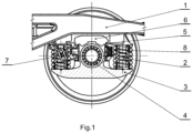
- Friction damper operates in the bogie suspension system that includes frame 1 articulated on the wagon chassis, supported on either side by spring kits 2 placed on the fifth wheel couplings 3.
- the fifth wheel 3 is placed on the axle box 4.
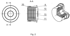
- Damper 8 features a guide cylinder 9 that is closed from one side with a closing cap 10, while it has an inner flange on the other side.
- the friction element 12 is in the shape of a flanged cylinder hidden inside the guide cylinder 9, whereas the remaining part protrudes more or less outside the guide cylinder 9.
- the friction element 12 presses onto the disc spring 11, while when it expands, the element protrudes outside until it rests its flange on the inner flange.
- the friction element 12 has a cylindrical groove 13 to mark the wear of the friction surface.
- the closing cap 10 can be screwed onto the guide cylinder 9, press-fitted or permanently affixed.
- a cylinder spring can be used as the spring element, or any other tensile material, such as elastomer or rubber.
Landscapes
- Engineering & Computer Science (AREA)
- General Engineering & Computer Science (AREA)
- Mechanical Engineering (AREA)
- Springs (AREA)
- Fluid-Damping Devices (AREA)
Description
- The patent application discloses a friction damper, particularly in a bogie suspension system, principally in four-axle freight wagons on bogies.
- Previously known suspensions systems are constructed in a way whereby, on either side of the chassis frame, the suspension zone relies on bases, each of which is supported by a kit of springs on the accompanying fifth-wheel coupling. The fifth wheel, in turn, is placed on the axle box. Each base features a space at the centre that is limited by surfaces that work with the fifth wheel columns. Between the fifth wheel columns and the cooperating base surfaces, on either side of the column, friction wedges are applied, supported on the springs placed on the fifth wheel. Friction wedges are usually triangular, with various surface angles, with inserts placed on the wedge, fifth wheel and base surfaces that work together. Resistance to the glide of the friction wedge against the base and the fifth wheel, which itself provides for movement damping, is achieved owing to friction created between the wedge and the fifth wheel column. Such a composition of technical measures, in some weather conditions, in the case of improper material selection, incorrect shaping of cooperating parts, and insufficient rigidity, particularly lateral, of springs that stabilise the suspension, may result in various forces causing improper wedge function in stroke damping. Such changes are undesired, and may lead to jamming, which consequently causes incorrect placement of the bogie both on the straight track and on the curve. This results in higher rolling resistance and damage to the bogies and rails. Similar solutions are known from the Canadian patent specifications No.
CA920430(A ) and No.CA969806(A ), which refer to rail car suspension systems, wherein the friction wedge insert has a cross-section of a truncated triangle. - Polish patent specification
PL207920(B - A bogie guide is known from the Polish patent specification
PL173525(B -
Polish patent application No. 340 485 (A - German patent application
DE 2110072(A1 ) discloses an axle guide on a bogie for rail vehicles, in particularly for freight wagons, in which coil springs are arranged between the axle bearing housing and the bogie frame on both sides of the wheel axle, one end in which is supposed on a movable intermediate part, trough which between the bogie frame and the axle bearing housing friction dampers which are arranged and are effective in the vertical and, if necessary, the horizontal transverse direction are acted upon by a force acting in the longitudinal direction and dependent on the loading of the helical spring in the vertical direction. Between the bogie frame and the axle bearing housing there is at least one force acting in the longitudinal direction of the bogie additional spring is arranged, which is acted upon by the intermediate part with a load dependent bias. - The invention is a friction damper, particularly suitable for a bogie suspension system, according to
claim 1. The key feature of the solution according to the invention consists in the fact that the guide cylinder is terminated on one side with a C-shaped horizontal closing cap, that includes the external wall of the cylinder, with an inner flange on the other side. The spring element placed inside the guide cylinder is adjacent to a slidable friction element in the shape of a cylinder with a flange the diameter of which corresponds to the inner diameter of the guide cylinder, while the remaining part of the friction element protrudes outside the cylinder. Moreover, in the most stretched position of the spring element, the flange of the friction element rests on the flange of the guide cylinder. - The closing cap is connected to the guide cylinder either permanently or in a dismantlable manner.
- The spring element can be formed by a disc spring. The spring element can be reformed by a cylinder spring.
- The spring element can be formed by elastomer.
- The spring element can be formed by rubber.
- The friction element can have a cylindrical groove that marks the wear of the bottom friction surface.
- The merit of this solution according to the invention lies in the application of an additional friction damper that introduces an additional spring element along the bogie, and allows radial positioning of the wheelsets at the curve. The damper structure allows smooth regulation of the preliminary tension force of the spring element, facilitates the assembly, and reduces the costs of friction damper maintenance.
- The solution according to the invention has been presented in the drawing, where
Fig. 1 presents the friction damper in the bogie suspension system, whileFig. 2 presents the friction damper structure. - Friction damper operates in the bogie suspension system that includes
frame 1 articulated on the wagon chassis, supported on either side byspring kits 2 placed on thefifth wheel couplings 3. Thefifth wheel 3 is placed on theaxle box 4. Between theguides 5 with the cooperatingfifth wheel coupling 3 andframe 1, there isfree space 6, whereas friction dampers are placed in theguides 5. In oneguide 5, there is a mushroom-shaped friction insert 7, while in the other, between thefifth wheel 3 and the guide, there is thecylindrical friction damper 8. - Damper 8 features a
guide cylinder 9 that is closed from one side with aclosing cap 10, while it has an inner flange on the other side. Inside theguide cylinder 9, there is adisc spring 11, with anadjacent friction element 12 that slides inside theguide cylinder 9 along its axis. Thefriction element 12 is in the shape of a flanged cylinder hidden inside theguide cylinder 9, whereas the remaining part protrudes more or less outside theguide cylinder 9. Thefriction element 12 presses onto thedisc spring 11, while when it expands, the element protrudes outside until it rests its flange on the inner flange. Furthermore, thefriction element 12 has acylindrical groove 13 to mark the wear of the friction surface. - The
closing cap 10 can be screwed onto theguide cylinder 9, press-fitted or permanently affixed. Instead of the disc spring, a cylinder spring can be used as the spring element, or any other tensile material, such as elastomer or rubber.
Claims (8)
- A friction damper, particularly suitable for a bogie suspension system, suitable to be placed in a guide (5) of the bogie suspension system, the friction damper containing a guide cylinder (9) suitable to be mounted between a fifth wheel coupling (3) of the bogie suspension system and the guide (5) of the bogie suspension system, which guide cylinder (9) is closed from one side and has a spring element (11) inside, which guide cylinder (9) comprises a slidable friction element (12), characterised in that the guide cylinder (9) is closed from one side by a closing cap (10), in the shape of a horizontal C that includes the outer wall of the guide cylinder (9) when mounted horizontally, with an inner flange on the opposite side, whereas the spring element (11) placed inside the guide cylinder (9) is adjacent to the slidable friction element (12) in the shape of a cylinder fitted with a flange the diameter of which corresponds to the inner diameter of the guide cylinder (9), whereas the flange is located inside the guide cylinder (9), while the remaining part of the friction element (12) protrudes outside the guide cylinder (9); wherein, when the spring element (11) is most stretched, the flange of the friction element (12) rests on the inner flange of the guide cylinder (9).
- The friction damper according to claim 1 characterised in that the closing cap (10) is dismantlable from the guide cylinder (9).
- The friction damper according to claim 1 characterised in that the closing cap (10) is permanently attached to the guide cylinder (9).
- The friction damper according to claim 1 characterised in that the spring element (11) is formed by a disc spring.
- The friction damper according to claim 1 characterised in that the spring element (11) is formed by a cylinder spring.
- The friction damper according to claim 1 characterised in that the spring element (11) is formed by elastomer.
- The friction damper according to claim 1 characterised in that the spring element (11) is formed by rubber.
- The friction damper according to claim 1 characterised in that the friction element (12) comprises a cylindrical groove (13) to mark the wear of its friction surface.
Applications Claiming Priority (2)
| Application Number | Priority Date | Filing Date | Title |
|---|---|---|---|
| PL128935U PL72915Y1 (en) | 2020-02-07 | 2020-02-07 | Friction damper, in aparticular in a rail bogie suspension system |
| PCT/PL2021/000005 WO2021158135A1 (en) | 2020-02-07 | 2021-02-03 | Friction damper, particularly in bogie suspension system |
Publications (2)
| Publication Number | Publication Date |
|---|---|
| EP4065447A1 EP4065447A1 (en) | 2022-10-05 |
| EP4065447B1 true EP4065447B1 (en) | 2024-08-21 |
Family
ID=75107992
Family Applications (1)
| Application Number | Title | Priority Date | Filing Date |
|---|---|---|---|
| EP21714280.1A Active EP4065447B1 (en) | 2020-02-07 | 2021-02-03 | Friction damper, particularly in bogie suspension system |
Country Status (3)
| Country | Link |
|---|---|
| EP (1) | EP4065447B1 (en) |
| PL (1) | PL72915Y1 (en) |
| WO (1) | WO2021158135A1 (en) |
Cited By (1)
| Publication number | Priority date | Publication date | Assignee | Title |
|---|---|---|---|---|
| EP4737260A1 (en) * | 2024-10-23 | 2026-05-06 | Greenbrier Poland sp. z o.o. | Friction damper |
Family Cites Families (6)
| Publication number | Priority date | Publication date | Assignee | Title |
|---|---|---|---|---|
| DE2110072C3 (en) * | 1971-03-03 | 1981-07-30 | Wegmann & Co, 3500 Kassel | Axle guide on a bogie for rail vehicles, in particular for freight wagons |
| US3835789A (en) * | 1971-07-28 | 1974-09-17 | Gloucester Railway Carriage | Snubbed railway bogies |
| FR2490172A1 (en) * | 1980-09-17 | 1982-03-19 | Sncf | SUSPENSION ARRANGEMENT FOR RAILWAY VEHICLES |
| DE19925634A1 (en) * | 1999-06-04 | 2000-12-14 | Dwa Deutsche Waggonbau Gmbh | Running gear for rail vehicles |
| GB0311480D0 (en) * | 2003-05-20 | 2003-06-25 | Powell Duffryn Rail Ltd | Improvements in the track friendliness of Y25 bogie |
| CN201165233Y (en) * | 2007-12-27 | 2008-12-17 | 齐齐哈尔轨道交通装备有限责任公司 | Lorry bogie axle box shock-absorbing device, bogie and lorry thereof |
-
2020
- 2020-02-07 PL PL128935U patent/PL72915Y1/en unknown
-
2021
- 2021-02-03 EP EP21714280.1A patent/EP4065447B1/en active Active
- 2021-02-03 WO PCT/PL2021/000005 patent/WO2021158135A1/en not_active Ceased
Cited By (1)
| Publication number | Priority date | Publication date | Assignee | Title |
|---|---|---|---|---|
| EP4737260A1 (en) * | 2024-10-23 | 2026-05-06 | Greenbrier Poland sp. z o.o. | Friction damper |
Also Published As
| Publication number | Publication date |
|---|---|
| PL72915Y1 (en) | 2023-02-27 |
| EP4065447A1 (en) | 2022-10-05 |
| WO2021158135A1 (en) | 2021-08-12 |
| PL128935U1 (en) | 2021-03-08 |
Similar Documents
| Publication | Publication Date | Title |
|---|---|---|
| CA1060932A (en) | Railway truck side bearing | |
| US4924779A (en) | Long-travel side bearing for an articulated railroad car | |
| US20080035012A1 (en) | Railway freight car side bearing | |
| CN102197186A (en) | Device for suspending a sliding door | |
| US7546807B2 (en) | Constant contact side bearing | |
| US5315934A (en) | Constant contact side bearings with spring biased sliding wedges | |
| CA2846165A1 (en) | Stabilized railway freight car truck | |
| US2324267A (en) | Truck | |
| US5036774A (en) | Long-travel side bearing for an articulated railroad car | |
| US5331902A (en) | Truck boltser with laterally wider friction show pocket and mechanism for lateral travel of the friction shoe | |
| AU2018201619A1 (en) | Railway car truck friction shoe spring group | |
| US3981548A (en) | Constant contact side bearing | |
| EP4100294B1 (en) | Friction damper for a bogie suspension system | |
| RU102577U1 (en) | SIDE FRAME OF THE TRUCK OF A CAR | |
| WO2021158135A1 (en) | Friction damper, particularly in bogie suspension system | |
| US5090333A (en) | Bogie for high-speed railborne vehicle | |
| CA2945287C (en) | Side bearing for railway car truck | |
| EP3045372B1 (en) | Spring-enhanched friction damper supported by a joint | |
| US8225720B2 (en) | Friction damping system for a railway truck | |
| CN108569308A (en) | Passive steering for piece rail road bogie | |
| SU1682227A1 (en) | Four-wheel rail vehicle | |
| EP4737260A1 (en) | Friction damper | |
| AU2018201609B2 (en) | Railway car truck friction shoe | |
| CN107253483B (en) | Railway wagon bogie | |
| RU1773768C (en) | Side support installation for rail vehicle |
Legal Events
| Date | Code | Title | Description |
|---|---|---|---|
| STAA | Information on the status of an ep patent application or granted ep patent |
Free format text: STATUS: UNKNOWN |
|
| STAA | Information on the status of an ep patent application or granted ep patent |
Free format text: STATUS: THE INTERNATIONAL PUBLICATION HAS BEEN MADE |
|
| PUAI | Public reference made under article 153(3) epc to a published international application that has entered the european phase |
Free format text: ORIGINAL CODE: 0009012 |
|
| STAA | Information on the status of an ep patent application or granted ep patent |
Free format text: STATUS: REQUEST FOR EXAMINATION WAS MADE |
|
| 17P | Request for examination filed |
Effective date: 20220701 |
|
| AK | Designated contracting states |
Kind code of ref document: A1 Designated state(s): AL AT BE BG CH CY CZ DE DK EE ES FI FR GB GR HR HU IE IS IT LI LT LU LV MC MK MT NL NO PL PT RO RS SE SI SK SM TR |
|
| DAV | Request for validation of the european patent (deleted) | ||
| DAX | Request for extension of the european patent (deleted) | ||
| REG | Reference to a national code |
Ref country code: DE Ref legal event code: R079 Free format text: PREVIOUS MAIN CLASS: B61F0005300000 Ipc: F16F0001320000 Ref document number: 602021017518 Country of ref document: DE |
|
| GRAP | Despatch of communication of intention to grant a patent |
Free format text: ORIGINAL CODE: EPIDOSNIGR1 |
|
| STAA | Information on the status of an ep patent application or granted ep patent |
Free format text: STATUS: GRANT OF PATENT IS INTENDED |
|
| RIC1 | Information provided on ipc code assigned before grant |
Ipc: B61F 5/30 20060101ALI20240221BHEP Ipc: F16F 7/09 20060101ALI20240221BHEP Ipc: F16F 3/02 20060101ALI20240221BHEP Ipc: F16F 1/32 20060101AFI20240221BHEP |
|
| INTG | Intention to grant announced |
Effective date: 20240314 |
|
| GRAS | Grant fee paid |
Free format text: ORIGINAL CODE: EPIDOSNIGR3 |
|
| GRAA | (expected) grant |
Free format text: ORIGINAL CODE: 0009210 |
|
| STAA | Information on the status of an ep patent application or granted ep patent |
Free format text: STATUS: THE PATENT HAS BEEN GRANTED |
|
| AK | Designated contracting states |
Kind code of ref document: B1 Designated state(s): AL AT BE BG CH CY CZ DE DK EE ES FI FR GB GR HR HU IE IS IT LI LT LU LV MC MK MT NL NO PL PT RO RS SE SI SK SM TR |
|
| REG | Reference to a national code |
Ref country code: GB Ref legal event code: FG4D |
|
| REG | Reference to a national code |
Ref country code: CH Ref legal event code: EP |
|
| REG | Reference to a national code |
Ref country code: IE Ref legal event code: FG4D |
|
| REG | Reference to a national code |
Ref country code: DE Ref legal event code: R096 Ref document number: 602021017518 Country of ref document: DE |
|
| REG | Reference to a national code |
Ref country code: LT Ref legal event code: MG9D |
|
| REG | Reference to a national code |
Ref country code: NL Ref legal event code: MP Effective date: 20240821 |
|
| PG25 | Lapsed in a contracting state [announced via postgrant information from national office to epo] |
Ref country code: NO Free format text: LAPSE BECAUSE OF FAILURE TO SUBMIT A TRANSLATION OF THE DESCRIPTION OR TO PAY THE FEE WITHIN THE PRESCRIBED TIME-LIMIT Effective date: 20241121 |
|
| REG | Reference to a national code |
Ref country code: AT Ref legal event code: MK05 Ref document number: 1715744 Country of ref document: AT Kind code of ref document: T Effective date: 20240821 |
|
| PG25 | Lapsed in a contracting state [announced via postgrant information from national office to epo] |
Ref country code: NL Free format text: LAPSE BECAUSE OF FAILURE TO SUBMIT A TRANSLATION OF THE DESCRIPTION OR TO PAY THE FEE WITHIN THE PRESCRIBED TIME-LIMIT Effective date: 20240821 Ref country code: PL Free format text: LAPSE BECAUSE OF FAILURE TO SUBMIT A TRANSLATION OF THE DESCRIPTION OR TO PAY THE FEE WITHIN THE PRESCRIBED TIME-LIMIT Effective date: 20240821 Ref country code: PT Free format text: LAPSE BECAUSE OF FAILURE TO SUBMIT A TRANSLATION OF THE DESCRIPTION OR TO PAY THE FEE WITHIN THE PRESCRIBED TIME-LIMIT Effective date: 20241223 Ref country code: GR Free format text: LAPSE BECAUSE OF FAILURE TO SUBMIT A TRANSLATION OF THE DESCRIPTION OR TO PAY THE FEE WITHIN THE PRESCRIBED TIME-LIMIT Effective date: 20241122 Ref country code: FI Free format text: LAPSE BECAUSE OF FAILURE TO SUBMIT A TRANSLATION OF THE DESCRIPTION OR TO PAY THE FEE WITHIN THE PRESCRIBED TIME-LIMIT Effective date: 20240821 |
|
| PG25 | Lapsed in a contracting state [announced via postgrant information from national office to epo] |
Ref country code: BG Free format text: LAPSE BECAUSE OF FAILURE TO SUBMIT A TRANSLATION OF THE DESCRIPTION OR TO PAY THE FEE WITHIN THE PRESCRIBED TIME-LIMIT Effective date: 20240821 |
|
| PG25 | Lapsed in a contracting state [announced via postgrant information from national office to epo] |
Ref country code: LV Free format text: LAPSE BECAUSE OF FAILURE TO SUBMIT A TRANSLATION OF THE DESCRIPTION OR TO PAY THE FEE WITHIN THE PRESCRIBED TIME-LIMIT Effective date: 20240821 |
|
| PG25 | Lapsed in a contracting state [announced via postgrant information from national office to epo] |
Ref country code: AT Free format text: LAPSE BECAUSE OF FAILURE TO SUBMIT A TRANSLATION OF THE DESCRIPTION OR TO PAY THE FEE WITHIN THE PRESCRIBED TIME-LIMIT Effective date: 20240821 Ref country code: IS Free format text: LAPSE BECAUSE OF FAILURE TO SUBMIT A TRANSLATION OF THE DESCRIPTION OR TO PAY THE FEE WITHIN THE PRESCRIBED TIME-LIMIT Effective date: 20241221 |
|
| PG25 | Lapsed in a contracting state [announced via postgrant information from national office to epo] |
Ref country code: HR Free format text: LAPSE BECAUSE OF FAILURE TO SUBMIT A TRANSLATION OF THE DESCRIPTION OR TO PAY THE FEE WITHIN THE PRESCRIBED TIME-LIMIT Effective date: 20240821 |
|
| PG25 | Lapsed in a contracting state [announced via postgrant information from national office to epo] |
Ref country code: ES Free format text: LAPSE BECAUSE OF FAILURE TO SUBMIT A TRANSLATION OF THE DESCRIPTION OR TO PAY THE FEE WITHIN THE PRESCRIBED TIME-LIMIT Effective date: 20240821 Ref country code: RS Free format text: LAPSE BECAUSE OF FAILURE TO SUBMIT A TRANSLATION OF THE DESCRIPTION OR TO PAY THE FEE WITHIN THE PRESCRIBED TIME-LIMIT Effective date: 20241121 |
|
| PG25 | Lapsed in a contracting state [announced via postgrant information from national office to epo] |
Ref country code: RS Free format text: LAPSE BECAUSE OF FAILURE TO SUBMIT A TRANSLATION OF THE DESCRIPTION OR TO PAY THE FEE WITHIN THE PRESCRIBED TIME-LIMIT Effective date: 20241121 Ref country code: PT Free format text: LAPSE BECAUSE OF FAILURE TO SUBMIT A TRANSLATION OF THE DESCRIPTION OR TO PAY THE FEE WITHIN THE PRESCRIBED TIME-LIMIT Effective date: 20241223 Ref country code: PL Free format text: LAPSE BECAUSE OF FAILURE TO SUBMIT A TRANSLATION OF THE DESCRIPTION OR TO PAY THE FEE WITHIN THE PRESCRIBED TIME-LIMIT Effective date: 20240821 Ref country code: NO Free format text: LAPSE BECAUSE OF FAILURE TO SUBMIT A TRANSLATION OF THE DESCRIPTION OR TO PAY THE FEE WITHIN THE PRESCRIBED TIME-LIMIT Effective date: 20241121 Ref country code: NL Free format text: LAPSE BECAUSE OF FAILURE TO SUBMIT A TRANSLATION OF THE DESCRIPTION OR TO PAY THE FEE WITHIN THE PRESCRIBED TIME-LIMIT Effective date: 20240821 Ref country code: LV Free format text: LAPSE BECAUSE OF FAILURE TO SUBMIT A TRANSLATION OF THE DESCRIPTION OR TO PAY THE FEE WITHIN THE PRESCRIBED TIME-LIMIT Effective date: 20240821 Ref country code: IS Free format text: LAPSE BECAUSE OF FAILURE TO SUBMIT A TRANSLATION OF THE DESCRIPTION OR TO PAY THE FEE WITHIN THE PRESCRIBED TIME-LIMIT Effective date: 20241221 Ref country code: HR Free format text: LAPSE BECAUSE OF FAILURE TO SUBMIT A TRANSLATION OF THE DESCRIPTION OR TO PAY THE FEE WITHIN THE PRESCRIBED TIME-LIMIT Effective date: 20240821 Ref country code: GR Free format text: LAPSE BECAUSE OF FAILURE TO SUBMIT A TRANSLATION OF THE DESCRIPTION OR TO PAY THE FEE WITHIN THE PRESCRIBED TIME-LIMIT Effective date: 20241122 Ref country code: FI Free format text: LAPSE BECAUSE OF FAILURE TO SUBMIT A TRANSLATION OF THE DESCRIPTION OR TO PAY THE FEE WITHIN THE PRESCRIBED TIME-LIMIT Effective date: 20240821 Ref country code: ES Free format text: LAPSE BECAUSE OF FAILURE TO SUBMIT A TRANSLATION OF THE DESCRIPTION OR TO PAY THE FEE WITHIN THE PRESCRIBED TIME-LIMIT Effective date: 20240821 Ref country code: BG Free format text: LAPSE BECAUSE OF FAILURE TO SUBMIT A TRANSLATION OF THE DESCRIPTION OR TO PAY THE FEE WITHIN THE PRESCRIBED TIME-LIMIT Effective date: 20240821 Ref country code: AT Free format text: LAPSE BECAUSE OF FAILURE TO SUBMIT A TRANSLATION OF THE DESCRIPTION OR TO PAY THE FEE WITHIN THE PRESCRIBED TIME-LIMIT Effective date: 20240821 |
|
| PG25 | Lapsed in a contracting state [announced via postgrant information from national office to epo] |
Ref country code: RO Free format text: LAPSE BECAUSE OF FAILURE TO SUBMIT A TRANSLATION OF THE DESCRIPTION OR TO PAY THE FEE WITHIN THE PRESCRIBED TIME-LIMIT Effective date: 20240821 Ref country code: DK Free format text: LAPSE BECAUSE OF FAILURE TO SUBMIT A TRANSLATION OF THE DESCRIPTION OR TO PAY THE FEE WITHIN THE PRESCRIBED TIME-LIMIT Effective date: 20240821 Ref country code: SM Free format text: LAPSE BECAUSE OF FAILURE TO SUBMIT A TRANSLATION OF THE DESCRIPTION OR TO PAY THE FEE WITHIN THE PRESCRIBED TIME-LIMIT Effective date: 20240821 |
|
| PG25 | Lapsed in a contracting state [announced via postgrant information from national office to epo] |
Ref country code: EE Free format text: LAPSE BECAUSE OF FAILURE TO SUBMIT A TRANSLATION OF THE DESCRIPTION OR TO PAY THE FEE WITHIN THE PRESCRIBED TIME-LIMIT Effective date: 20240821 |
|
| PG25 | Lapsed in a contracting state [announced via postgrant information from national office to epo] |
Ref country code: IT Free format text: LAPSE BECAUSE OF FAILURE TO SUBMIT A TRANSLATION OF THE DESCRIPTION OR TO PAY THE FEE WITHIN THE PRESCRIBED TIME-LIMIT Effective date: 20240821 |
|
| REG | Reference to a national code |
Ref country code: DE Ref legal event code: R097 Ref document number: 602021017518 Country of ref document: DE |
|
| REG | Reference to a national code |
Ref country code: SK Ref legal event code: T3 Ref document number: E 46128 Country of ref document: SK |
|
| PLBE | No opposition filed within time limit |
Free format text: ORIGINAL CODE: 0009261 |
|
| STAA | Information on the status of an ep patent application or granted ep patent |
Free format text: STATUS: NO OPPOSITION FILED WITHIN TIME LIMIT |
|
| PGFP | Annual fee paid to national office [announced via postgrant information from national office to epo] |
Ref country code: SK Payment date: 20250514 Year of fee payment: 5 |
|
| PGFP | Annual fee paid to national office [announced via postgrant information from national office to epo] |
Ref country code: CZ Payment date: 20250514 Year of fee payment: 5 |
|
| 26N | No opposition filed |
Effective date: 20250522 |
|
| REG | Reference to a national code |
Ref country code: DE Ref legal event code: R119 Ref document number: 602021017518 Country of ref document: DE |
|
| PG25 | Lapsed in a contracting state [announced via postgrant information from national office to epo] |
Ref country code: SE Free format text: LAPSE BECAUSE OF FAILURE TO SUBMIT A TRANSLATION OF THE DESCRIPTION OR TO PAY THE FEE WITHIN THE PRESCRIBED TIME-LIMIT Effective date: 20240821 |
|
| PG25 | Lapsed in a contracting state [announced via postgrant information from national office to epo] |
Ref country code: MC Free format text: LAPSE BECAUSE OF FAILURE TO SUBMIT A TRANSLATION OF THE DESCRIPTION OR TO PAY THE FEE WITHIN THE PRESCRIBED TIME-LIMIT Effective date: 20240821 |
|
| REG | Reference to a national code |
Ref country code: CH Ref legal event code: PL |
|
| PG25 | Lapsed in a contracting state [announced via postgrant information from national office to epo] |
Ref country code: LU Free format text: LAPSE BECAUSE OF NON-PAYMENT OF DUE FEES Effective date: 20250203 |
|
| PG25 | Lapsed in a contracting state [announced via postgrant information from national office to epo] |
Ref country code: CH Free format text: LAPSE BECAUSE OF NON-PAYMENT OF DUE FEES Effective date: 20250228 |
|
| GBPC | Gb: european patent ceased through non-payment of renewal fee |
Effective date: 20250203 |
|
| REG | Reference to a national code |
Ref country code: BE Ref legal event code: MM Effective date: 20250228 |
|
| PG25 | Lapsed in a contracting state [announced via postgrant information from national office to epo] |
Ref country code: DE Free format text: LAPSE BECAUSE OF NON-PAYMENT OF DUE FEES Effective date: 20250902 |
|
| PG25 | Lapsed in a contracting state [announced via postgrant information from national office to epo] |
Ref country code: GB Free format text: LAPSE BECAUSE OF NON-PAYMENT OF DUE FEES Effective date: 20250203 |
|
| PG25 | Lapsed in a contracting state [announced via postgrant information from national office to epo] |
Ref country code: FR Free format text: LAPSE BECAUSE OF NON-PAYMENT OF DUE FEES Effective date: 20250228 |
|
| PG25 | Lapsed in a contracting state [announced via postgrant information from national office to epo] |
Ref country code: BE Free format text: LAPSE BECAUSE OF NON-PAYMENT OF DUE FEES Effective date: 20250228 |
|
| PG25 | Lapsed in a contracting state [announced via postgrant information from national office to epo] |
Ref country code: IE Free format text: LAPSE BECAUSE OF NON-PAYMENT OF DUE FEES Effective date: 20250203 |