EP4065296B1 - Hot stamp tooling assembly and method of forming a part with tailored temper properties - Google Patents
Hot stamp tooling assembly and method of forming a part with tailored temper properties Download PDFInfo
- Publication number
- EP4065296B1 EP4065296B1 EP20891842.5A EP20891842A EP4065296B1 EP 4065296 B1 EP4065296 B1 EP 4065296B1 EP 20891842 A EP20891842 A EP 20891842A EP 4065296 B1 EP4065296 B1 EP 4065296B1
- Authority
- EP
- European Patent Office
- Prior art keywords
- die
- annealing
- shaped part
- hot
- forming die
- Prior art date
- Legal status (The legal status is an assumption and is not a legal conclusion. Google has not performed a legal analysis and makes no representation as to the accuracy of the status listed.)
- Active
Links
Images




Classifications
-
- C—CHEMISTRY; METALLURGY
- C21—METALLURGY OF IRON
- C21D—MODIFYING THE PHYSICAL STRUCTURE OF FERROUS METALS; GENERAL DEVICES FOR HEAT TREATMENT OF FERROUS OR NON-FERROUS METALS OR ALLOYS; MAKING METAL MALLEABLE, e.g. BY DECARBURISATION OR TEMPERING
- C21D1/00—General methods or devices for heat treatment, e.g. annealing, hardening, quenching or tempering
- C21D1/62—Quenching devices
- C21D1/673—Quenching devices for die quenching
-
- B—PERFORMING OPERATIONS; TRANSPORTING
- B21—MECHANICAL METAL-WORKING WITHOUT ESSENTIALLY REMOVING MATERIAL; PUNCHING METAL
- B21D—WORKING OR PROCESSING OF SHEET METAL OR METAL TUBES, RODS OR PROFILES WITHOUT ESSENTIALLY REMOVING MATERIAL; PUNCHING METAL
- B21D22/00—Shaping without cutting, by stamping, spinning, or deep-drawing
- B21D22/02—Stamping using rigid devices or tools
- B21D22/022—Stamping using rigid devices or tools by heating the blank or stamping associated with heat treatment
-
- B—PERFORMING OPERATIONS; TRANSPORTING
- B21—MECHANICAL METAL-WORKING WITHOUT ESSENTIALLY REMOVING MATERIAL; PUNCHING METAL
- B21D—WORKING OR PROCESSING OF SHEET METAL OR METAL TUBES, RODS OR PROFILES WITHOUT ESSENTIALLY REMOVING MATERIAL; PUNCHING METAL
- B21D22/00—Shaping without cutting, by stamping, spinning, or deep-drawing
- B21D22/20—Deep-drawing
- B21D22/208—Deep-drawing by heating the blank or deep-drawing associated with heat treatment
-
- B—PERFORMING OPERATIONS; TRANSPORTING
- B21—MECHANICAL METAL-WORKING WITHOUT ESSENTIALLY REMOVING MATERIAL; PUNCHING METAL
- B21D—WORKING OR PROCESSING OF SHEET METAL OR METAL TUBES, RODS OR PROFILES WITHOUT ESSENTIALLY REMOVING MATERIAL; PUNCHING METAL
- B21D37/00—Tools as parts of machines covered by this subclass
- B21D37/08—Dies with different parts for several steps in a process
-
- B—PERFORMING OPERATIONS; TRANSPORTING
- B21—MECHANICAL METAL-WORKING WITHOUT ESSENTIALLY REMOVING MATERIAL; PUNCHING METAL
- B21D—WORKING OR PROCESSING OF SHEET METAL OR METAL TUBES, RODS OR PROFILES WITHOUT ESSENTIALLY REMOVING MATERIAL; PUNCHING METAL
- B21D37/00—Tools as parts of machines covered by this subclass
- B21D37/16—Heating or cooling
-
- C—CHEMISTRY; METALLURGY
- C21—METALLURGY OF IRON
- C21D—MODIFYING THE PHYSICAL STRUCTURE OF FERROUS METALS; GENERAL DEVICES FOR HEAT TREATMENT OF FERROUS OR NON-FERROUS METALS OR ALLOYS; MAKING METAL MALLEABLE, e.g. BY DECARBURISATION OR TEMPERING
- C21D1/00—General methods or devices for heat treatment, e.g. annealing, hardening, quenching or tempering
- C21D1/26—Methods of annealing
-
- C—CHEMISTRY; METALLURGY
- C21—METALLURGY OF IRON
- C21D—MODIFYING THE PHYSICAL STRUCTURE OF FERROUS METALS; GENERAL DEVICES FOR HEAT TREATMENT OF FERROUS OR NON-FERROUS METALS OR ALLOYS; MAKING METAL MALLEABLE, e.g. BY DECARBURISATION OR TEMPERING
- C21D8/00—Modifying the physical properties of ferrous metals or ferrous alloys by deformation combined with, or followed by, heat treatment
-
- C—CHEMISTRY; METALLURGY
- C21—METALLURGY OF IRON
- C21D—MODIFYING THE PHYSICAL STRUCTURE OF FERROUS METALS; GENERAL DEVICES FOR HEAT TREATMENT OF FERROUS OR NON-FERROUS METALS OR ALLOYS; MAKING METAL MALLEABLE, e.g. BY DECARBURISATION OR TEMPERING
- C21D9/00—Heat treatment, e.g. annealing, hardening, quenching or tempering, adapted for particular articles; Furnaces therefor
- C21D9/0068—Heat treatment, e.g. annealing, hardening, quenching or tempering, adapted for particular articles; Furnaces therefor for particular articles not mentioned below
-
- B—PERFORMING OPERATIONS; TRANSPORTING
- B21—MECHANICAL METAL-WORKING WITHOUT ESSENTIALLY REMOVING MATERIAL; PUNCHING METAL
- B21D—WORKING OR PROCESSING OF SHEET METAL OR METAL TUBES, RODS OR PROFILES WITHOUT ESSENTIALLY REMOVING MATERIAL; PUNCHING METAL
- B21D35/00—Combined processes according to or processes combined with methods covered by groups B21D1/00 - B21D31/00
- B21D35/002—Processes combined with methods covered by groups B21D1/00 - B21D31/00
- B21D35/005—Processes combined with methods covered by groups B21D1/00 - B21D31/00 characterized by the material of the blank or the workpiece
- B21D35/007—Layered blanks
-
- C—CHEMISTRY; METALLURGY
- C21—METALLURGY OF IRON
- C21D—MODIFYING THE PHYSICAL STRUCTURE OF FERROUS METALS; GENERAL DEVICES FOR HEAT TREATMENT OF FERROUS OR NON-FERROUS METALS OR ALLOYS; MAKING METAL MALLEABLE, e.g. BY DECARBURISATION OR TEMPERING
- C21D1/00—General methods or devices for heat treatment, e.g. annealing, hardening, quenching or tempering
- C21D1/34—Methods of heating
- C21D1/42—Induction heating
-
- C—CHEMISTRY; METALLURGY
- C21—METALLURGY OF IRON
- C21D—MODIFYING THE PHYSICAL STRUCTURE OF FERROUS METALS; GENERAL DEVICES FOR HEAT TREATMENT OF FERROUS OR NON-FERROUS METALS OR ALLOYS; MAKING METAL MALLEABLE, e.g. BY DECARBURISATION OR TEMPERING
- C21D11/00—Process control or regulation for heat treatments
-
- C—CHEMISTRY; METALLURGY
- C21—METALLURGY OF IRON
- C21D—MODIFYING THE PHYSICAL STRUCTURE OF FERROUS METALS; GENERAL DEVICES FOR HEAT TREATMENT OF FERROUS OR NON-FERROUS METALS OR ALLOYS; MAKING METAL MALLEABLE, e.g. BY DECARBURISATION OR TEMPERING
- C21D11/00—Process control or regulation for heat treatments
- C21D11/005—Process control or regulation for heat treatments for cooling
-
- C—CHEMISTRY; METALLURGY
- C21—METALLURGY OF IRON
- C21D—MODIFYING THE PHYSICAL STRUCTURE OF FERROUS METALS; GENERAL DEVICES FOR HEAT TREATMENT OF FERROUS OR NON-FERROUS METALS OR ALLOYS; MAKING METAL MALLEABLE, e.g. BY DECARBURISATION OR TEMPERING
- C21D2221/00—Treating localised areas of an article
-
- Y—GENERAL TAGGING OF NEW TECHNOLOGICAL DEVELOPMENTS; GENERAL TAGGING OF CROSS-SECTIONAL TECHNOLOGIES SPANNING OVER SEVERAL SECTIONS OF THE IPC; TECHNICAL SUBJECTS COVERED BY FORMER USPC CROSS-REFERENCE ART COLLECTIONS [XRACs] AND DIGESTS
- Y02—TECHNOLOGIES OR APPLICATIONS FOR MITIGATION OR ADAPTATION AGAINST CLIMATE CHANGE
- Y02P—CLIMATE CHANGE MITIGATION TECHNOLOGIES IN THE PRODUCTION OR PROCESSING OF GOODS
- Y02P10/00—Technologies related to metal processing
- Y02P10/25—Process efficiency
Definitions
- the present invention relates a hot stamp tool assembly and a method of forming a part with tailored temper properties. More particularly, the present invention relates to a hot stamp tool assembly and a method for forming parts with small transition zones between temper locations.
- a hot stamping tool assembly having the features defined in claim 1
- a method of forming a part with tailor tempered properties and small transition zones having the features defined in claim 13 is provided. Further preferred embodiments are defined in the dependent claims.
- Example embodiments will now be described more fully with reference to the accompanying drawings.
- the subject embodiments are directed to a hot stamp tool assembly and a method of forming a part with tailored temper properties.
- the example embodiments are only provided so that this disclosure will be thorough, and will fully convey the scope to those who are skilled in the art. Numerous specific details are set forth such as examples of specific components, devices, and methods, to provide a thorough understanding of embodiments of the present disclosure. It will be apparent to those skilled in the art that specific details need not be employed, that example embodiments may be embodied in many different forms and that neither should be construed to limit the scope of the disclosure. In some example embodiments, well-known processes, well-known device structures, and well-known technologies are not described in detail.
- the first transfer arm 26 includes at least one blank holder 30, such as a hydraulically operated clamp, an energized magnet, a suction device, or any other implements conventionally utilized for moving blanks between locations.
- the at least one blank holder 30 may include a first blank holder and a second blank holder 30.
- the second transfer arm 28 includes at least one shaped part holder 32, such as a hydraulically operated clamp, an energized magnet, a suction device, or any other implements conventionally utilized for moving shaped blanks between locations.
- the at least one shaped part holder 32 may include a first shaped part holder, a second first shaped part holder, a third shaped part holder, and a fourth shaped part holder 32.
- the upper forming die channels 42 and the lower forming die channels 44 thus provide quenching of the shaped part 34B with liquid coolant that is circulated therein or static cooling devices that are located therein.
- the quenching process in the hot forming dies 22 may thus circulate coolant and change the microstructure in at least a portion of the shaped part 34B (e.g., forming martensite).
- the shaped part 34B is cooled at a rate of at least 27°C per second and martensite may be formed between 200°C and 400°C.
- the upper forming die 36 and the lower forming die 38 may define a bend portion 46 of the cavity 40 that forms a stiffener flange 35 in the shaped part 34B.
- Cooling channels 42, 44 may be located adjacent to the entire outline wherein the shaped part 34B will be located, including the bend portion 46 such that primarily the entire shaped part is quenched.
- the coolant in the forming die 22 may include a liquid, such as water, circulated at a temperature between 7°C and 38°C.
- FIGS 3A and 3B are cross-sectional side views of the annealing die 24 located within the hot stamp tool assembly 20.
- Each of the annealing dies 24 may include the same configuration and operational parameters.
- the annealing die 24 includes an upper annealing die 48 and an lower annealing die 50 defining an annealing cavity 52 therebetween. Inner surfaces of the upper annealing die 48 and an lower annealing die may include topographical features similar to that of the hot forming dies 22.
- the upper annealing die 48 includes a series of upper die channels 54 located adjacent to the annealing cavity 52 and the lower annealing die 50 includes a series of lower die channels 56 located adjacent to the annealing cavity 52.
- the upper die channels 54 and the lower die channels 56 may provide continued cooling of the shaped part 34B with coolant that is circulated therein or static cooling materials that are located therein.
- the cooling operation in the annealing die 24 may cause further reduce the temperature of portions of the shaped part 34B to between 0°C and 150°C.
- the coolant in the annealing die 24 may include a liquid, such as water, circulated at a temperature between 20°C and 35°C.
- the shaped part 34B is placed in the annealing die 24 once it reaches a temperature below 200°C.
- the upper annealing die 48 may include at least one upper heating element, such as an upper induction coil 58 located adjacent to the annealing cavity 52 and the lower annealing die 50 may include at least one lower heating element, such as a lower induction coil 60, located adjacent to the annealing cavity 52.
- the at least one lower induction coil 58 may be disposed adjacent to and on an opposite side of the cavity 52 from the at least one upper induction coil 60.
- the upper annealing die 48 includes two upper induction coils 58 located in a spaced relationship, wherein the series of upper die channels 54 are located between each of the upper induction coils 48.
- the lower annealing die 50 may include two lower induction coils 60 located in a spaced relationship, wherein the series of lower die channels 56 are located between each of the lower induction coils 60.
- the die channels 54, 56 are located on either side of the induction coils 58, 60.
- the induction coils 58, 60 are located at a trim location of the shaped part 34B.
- the induction coils 58, 60 may rapidly heat and anneal the shaped part 34B at the trim location while the cooling channels 54, 56 maintain a lower temperature on locations of the shaped part 34B adjacent to the induction coils 58, 60, thus decreasing the creeping effect of the heat transfer and a reducing the size of a transition zone between the annealed portions of the shaped part 34B and the non-annealed portions of the shaped portion 34B.
- the annealing die 24 may include a annealing die insert that includes an upper annealing die insert 62 and a lower annealing die insert 64 that can be moved independently of the upper annealing die 48 and the lower annealing die 50.
- the upper and lower annealing die inserts 62, 64 define an annealing insert cavity 66 with a bend 68 that accommodates the stiffener flange 35. Both annealing inserts 62, 64 are located on an outside portion of annealing die 24 from the induction coils 58, 60.
- the quenched area is spaced from the stiffener flange 35 by a portion of the annealed part 34C which has been softened through annealing.
- the stiffener flange 35 can later be removed via cutting. No cooling channels may be necessary next to the stiffener flange 35 if it will be removed.
- the die channels 54, 56 opposite the stiffener flange 35 hinder the transition zone from creeping into portions other than the annealed portion and the stiffener flange 35.
- the stiffener flange 35 also prevents distortion of the annealed part 34C during the annealing process.
- the die channels 54, 56 may be located on opposite sides of the induction coils 58, 60.
- the stiffener flange 35 may be quenched such that a trimming operation on the annealed portion is modified.
- the trim portion and/or trimming operation may include deforming, piercing, cutting, etc. without departure from the subject disclosure.
- the annealed portion may be completely surrounded by the quenched portions.
- the trim portion is inset from but outlines an entire or partial periphery of the annealed part 34C.
- the upper and lower annealing die inserts 62, 64 may perform the trimming operation.
- the memory 86 may include Random Access Memory (RAM), a Read-Only Memory (ROM), or a combination thereof.
- the memory 86 may include instructions that, when executed by the processor 84, cause the processor 84 to, at least, perform the systems and methods described herein.
- the controller 82 may control operations of the forming die 22, the annealing die 24, the first transfer arm 26, the second transfer arm 28, and other features.
- FIG 5 is a series of top views of the hot stamp tool illustrating sequential steps of a process 100 of forming tailored temper properties in a part with small transition zones. Each step in the process 100 may be carried out by instructions from the memory executed by the processor. Each of the hot stamp tools illustrated in Figure 5 is the same hot stamp tool as a function of time during the course of process 100.
- the process 100 begins with providing 102 a hot stamp tool having a pair of annealing dies and a pair of hot forming dies, wherein the hot forming dies each include a blank and the annealing dies each include a shaped part (which was previously a blank formed in one of the hot forming dies).
- the hot forming dies shape 106 the blanks into a shaped part and may further include a quenching 108 step, such as by a series of cooling channels, wherein a hardened microstructure may be formed within the shaped part.
- the annealing die simultaneously cools 110 and anneals 112 adjacent locations on the shaped part to form an annealed part.
- the step of annealing may include heating with an induction coil and the step of cooling may including cooling channels located adjacent to the induction coil.
- Figures 6A through 6F show enlarged steps 102 through 120 of the process 100. More particularly, Figure 6A illustrates providing 102 a hot stamp tool having a pair of annealing dies and a pair of hot forming dies, wherein the hot forming dies each include a blank and the annealing dies each include a shaped part (which was previously a blank formed in one of the hot forming dies).
- Figure 6B illustrates the second transfer arm grabbing 114 each of the shaped parts and each of the annealed parts and moving 116 the shaped parts to the annealing dies and moving 118 the annealed parts away from the hot stamp assembly.
- Figure 7 illustrates a series of cross-sectional views of a part undergoing a process 200 of forming tailored temper properties with small transition zones. Each step in the process 200 may be carried out by instructions from the memory executed by the processor. The process 200 presented in Figure 7 may be included with non-overlapping steps in process 100, for example, between steps 102 through 112. More particularly, the process begins by providing 202 a heated blank directly from a furnace. The heated blank is then placed 204 within a hot forming die, wherein it is shaped 206 and quenched 208 via cooling channels to from a shaped part with a hardened microstructure, e.g., higher levels of martensite.
- a hot forming die wherein it is shaped 206 and quenched 208 via cooling channels to from a shaped part with a hardened microstructure, e.g., higher levels of martensite.
- the shaped part is placed 210 within an annealing die, wherein it continues to be cooled 212 via die channels and locally annealed 214 with induction coils that are adjacent to the die channels.
- the step of cooling may include cooling portions of the shaped part adjacent to the induction coils to a temperature between 0°C and 150°C. The portion of the shaped part that is cooled is entirely within the space between adjacent pairs of induction coils presented in Figure 3A and Figure 3B .
- the local annealing 214 step may include forming an annealed portion within or adjacent to a non-annealed portion, wherein a transition zone at least partially separates the annealed portion from the non-annealed portion and at least part, a majority, or substantially all the transition zone is less that 20mm, less than 15mm, approximately 10mm, or less than 10mm.
- the later processing includes deforming 218 the annealed portion.
- the step of deforming 218 may include one of cutting, riveting, bending, piercing, trimming to size, etc.
- the step of cutting may including laser cutting.
- the resulting part 220 may be a part of an automobile for example a pillar and more specifically a B-pillar.
- Figure 8 illustrates a part 300 having at least one non-annealed portion 302 with a small transition zone 304 that includes at least one deformation 306. More particularly, the part 300 is illustrated as a B-pillar with a transition zone 304 forming an outer edge that includes a deformation 306 including a cut along a peripheral edge of the transition zone 304.
- Figure 9 is a flowchart of a method 400 of forming a part with tailored temper properties and small transition zones.
- the method 400 begins by hot forming 402 and quenching 404 a blank in a hot forming die until it is a shaped part 401.
- the step of quenching 404 may include changing the microstructure of the shaped part.
- the method 400 continues by placing 406 the shaped part in an annealing die wherein it is partially cooled 408 and partially heated 410, simultaneously and at adjacent locations, until it is an annealed part 407 with a small transition zone between the annealed portions and the non-annealed portions.
- a portion of the annealed part that was heated 410 i.e., an annealed portion of the annealed part
Landscapes
- Engineering & Computer Science (AREA)
- Chemical & Material Sciences (AREA)
- Mechanical Engineering (AREA)
- Physics & Mathematics (AREA)
- Thermal Sciences (AREA)
- Crystallography & Structural Chemistry (AREA)
- Materials Engineering (AREA)
- Metallurgy (AREA)
- Organic Chemistry (AREA)
- Heat Treatment Of Articles (AREA)
Description
- The present invention relates a hot stamp tool assembly and a method of forming a part with tailored temper properties. More particularly, the present invention relates to a hot stamp tool assembly and a method for forming parts with small transition zones between temper locations.
- This section provides background information related to the present disclosure which is not necessarily prior art.
- Continuing efforts to reduce weight and increase fuel efficiency have driven the automotive industry to develop metal with improved strength and ductility allowing the use of thinner gauges while still maintaining industrial safety standards. During production, these metals often start as metal blanks that are later stamped in to automotive parts. Depending on an end use, automotive parts require different levels of strength and ductility. For example, a part stamped for use in automobiles may be subjected to one type of stresses via rough driving surfaces, internal vibrations, and exposure to corrosive environments whereas a neighboring part may only be subjected to minimal stresses. Moreover, individual parts may be subjected to inconsistent stresses in localized areas. Because certain parts experience less hardship, they can be produced with lighter metals and metal alloys to satisfy specific strength or stiffness requirements. However, for those parts that are subjected the most stress, they are usually made of steel or steel alloy that is treated for optimized strength and ductility. These treatment methods typically involve some way of heating the part to temperatures at which the physical and sometimes chemical property of the underlying metal is changed. Depending on the constituents of the metal alloy used, when a part is heated to a certain temperature, the constituents can form an uninterrupted microstructure before being cooled. While these treated parts can be made at thinner gauges to reduce weight, treated parts have become so hard that they are difficult to shape and connect to other neighboring parts. In addition, oftentimes it is beneficial to develop a part with a localized area that is softer with increased ductility to improve absorption during an impact event.
- Attempts to produce parts with improved workability having localized areas with different levels of ductility and strength have resulted in the development of several processes in which localized areas of a part can be treated. One popular method involves heating a die between the stamping of metal parts. During this process, the die is heated to a temperature high enough to change the physical characteristics of the metal being stamped. However, it is hard to accurately heat treat a small or complex-shaped localized area without excess heat creeping into nearby portions. Moreover, the localized areas that are heat treated have large transition zones between a tempered location and a non-tempered location. Further relevant prior art is described in
US 2019/193134 ,EP 2 993 241 A1 ,KR 2001 0075732 A DE 10 2018 124425 A1 ,EP 3 037 186 A2 . - Accordingly, there is a continuing desire to further develop and refine tempering processes to limit the size of transition zones.
- The foregoing has outlined rather broadly the features and technical advantages of the present invention in order that the detailed description of the invention that follows may be better understood. Additional features and advantages of the invention will be described hereinafter that form the subject of the claims of the invention. It should be appreciated by those skilled in the art that the conception and the specific embodiments disclosed may be readily utilized as a basis for modifying or designing other embodiments for carrying out the same purposes of the present invention. It should also be realized by those skilled in the art that such equivalent embodiments do not depart from the spirit and scope of the invention as set forth in the appended claims. This section provides a general summary of the disclosure and is not to be interpreted as a complete and comprehensive listing of all of the objects, aspects, features and advantages associated with the present disclosure. In order to solve the aforementioned problem, a hot stamping tool assembly, having the features defined in claim 1, is provided. Further, a method of forming a part with tailor tempered properties and small transition zones, having the features defined in claim 13 is provided. Further preferred embodiments are defined in the dependent claims.
- Further areas of applicability will become apparent from the description provided herein. The description and specific examples in this summary are intended for purposes of illustration only and are not intended to limit the scope of the present disclosure.
- The drawings described herein are for illustrative purposes only of selected embodiments and are not intended to limit the scope of the present disclosure. The inventive concepts associated with the present disclosure will be more readily understood by reference to the following description in combination with the accompanying drawings wherein:
-
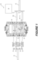
Figure 1 is a top view of a hot stamp tool assembly having a first transfer arm for placing parts into the hot stamp tool and a second transfer arm for removing parts from the hot stamp tool; -
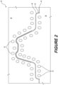
Figure 2 is a cross-sectional side view of a hot forming die located within the hot stamp tool assembly; -
Figure 3A is a cross-sectional side view of an annealing die located within the hot stamp tool assembly; -
Figure 3B is an enlarged cross-sectional side view of the annealing die presented inFigure 3A ; -
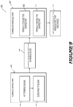
Figure 4 generally illustrates a block diagram of a controlling system of the hot stamp tool assembly; -
Figure 5 is a series of top views of the hot stamp tool illustrating a process of forming a part with tailored temper properties with small transition zones; -
Figure 6A is an enlarged top view of the hot stamp tool assembly in a first step of the process shown inFigure 4 ; -
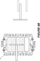
Figure 6B is an enlarged top view of the hot stamp tool assembly in a second step of the process shown inFigure 4 ; -
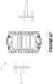
Figure 6C is an enlarged top view of the hot stamp tool assembly in a third step of the process shown inFigure 4 ; -
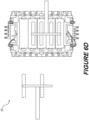
Figure 6D is an enlarged top view of the hot stamp tool assembly in a fourth step of the process shown inFigure 4 ; -
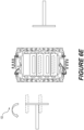
Figure 6E is an enlarged top view of the hot stamp tool assembly in a fifth step of the process shown inFigure 4 ; -
Figure 6F is an enlarged top view of the hot stamp tool assembly in a sixth step of the process shown inFigure 4 ; -
Figure 7 is a series of cross-sectional views of a part undergoing the process of forming tailored temper properties with small transition zones; -
Figure 8 is a top view of a part with tailored temper properties and small transition zones; and -
Figure 9 is a flow chart of a method for forming a part with tailored temper properties. - Example embodiments will now be described more fully with reference to the accompanying drawings. In general, the subject embodiments are directed to a hot stamp tool assembly and a method of forming a part with tailored temper properties. However, the example embodiments are only provided so that this disclosure will be thorough, and will fully convey the scope to those who are skilled in the art. Numerous specific details are set forth such as examples of specific components, devices, and methods, to provide a thorough understanding of embodiments of the present disclosure. It will be apparent to those skilled in the art that specific details need not be employed, that example embodiments may be embodied in many different forms and that neither should be construed to limit the scope of the disclosure. In some example embodiments, well-known processes, well-known device structures, and well-known technologies are not described in detail.
- Referring to the Figures, wherein like numerals indicate corresponding parts throughout the views, the hot stamp tool assembly and method of same ultimately provide a part with temper locations and non-temper locations and small transition zones between temper locations and non-temper locations.
- Referring initially to
Figure 1 , the hotstamp tool assembly 20 is generally shown. The hotstamp tool assembly 20 may include at least one hot forming die 22 (seeFigure 2 ) and at least one annealing die 24 (Figure 3A ). In some embodiments, the hotstamp tool assembly 20 includes a plurality of annealingdies 24, for example, a first annealing die andsecond annealing die 24 and a plurality of hot formingdies 22, for example, a first hot forming die and a second hot forming die 22. Afirst transfer arm 26 is located on one side of the hotstamp tool assembly 20 and asecond transfer arm 28 is located on an opposite side of the hotstamp tool assembly 20. Thefirst transfer arm 26 includes at least oneblank holder 30, such as a hydraulically operated clamp, an energized magnet, a suction device, or any other implements conventionally utilized for moving blanks between locations. In some embodiments, the at least oneblank holder 30 may include a first blank holder and a secondblank holder 30. Thesecond transfer arm 28 includes at least oneshaped part holder 32, such as a hydraulically operated clamp, an energized magnet, a suction device, or any other implements conventionally utilized for moving shaped blanks between locations. In some embodiments, the at least oneshaped part holder 32 may include a first shaped part holder, a second first shaped part holder, a third shaped part holder, and a fourthshaped part holder 32. - As illustrated by the arrows, the
first transfer arm 26 connects to a pair ofheated blanks 34A and removes them from afurnace 25 with a respective one of the firstblank holders 30 and simultaneously places one heated blank 34A in the first hot formingdie 22 and the other heated blank 34A in the second hot formingdie 22. Once theheated blanks 34A have been placed into the hot forming dies 22, a stroke of the hot forming dies 22 stamps each of theblanks 34A into ashaped part 34B. While located in the hot forming dies 22, the blanks may also be quenched. The combination of heating and rapidly cooling may change a microstructure of at least a portion of the shapedparts 34B. For example, the heating and quenching may result in the formation of martensitic in at least a portion of the shapedparts 34B. After shaped and quenched, thesecond transfer arm 28 removes the shapedparts 34B with two of theshaped part holders 32 and places oneshaped part 34B in the first annealing die 24 and the othershaped part 34B in the second annealing die 24. The shapedparts 34B then undergo an annealing process. For example, portions of the shaped parts 34 may be reheated to above a recrystallization temperature and then slowly cooled until they are annealed, thus becomingannealed parts 34C. While theshaped part 34B is located in the annealing die 24, it may further be subjected to additional cooling on portions of theshaped part 34B adjacent to those portions of theshaped part 34B that are annealed. Thesecond transfer arm 28 removes the annealedparts 34C with two of the othershaped part holders 32 that were not used in placing the shapedparts 34B into the annealing die 24. In operation, thesecond transfer arm 28 may thus simultaneously connect to two or moreshaped parts 34B and two or moreannealed parts 34C with each of theshaped part holders 32 and move the shapedparts 34B between the forming dies 22 and the annealing dies 24 while removing the annealedparts 34C from the annealing dies 24 in one process step. -
Figure 2 is a cross-sectional side view of one of the hot forming dies 22 located within the hotstamp tool assembly 20. Each of the hot forming dies 22 may include the same configuration and operational parameters. The hot formingdie 22 includes a upper formingdie 36 and a lower formingdie 38 defining a formingcavity 40 therebetween. Inner surfaces of the upper formingdie 36 and the lower formingdie 38 may include topographical features to form theshaped part 34B into any number of shapes, including automotive components such as automotive pillars. The upper formingdie 36 includes a series of upper formingdie channels 42 located adjacent to the formingcavity 40 and the lower formingdie 38 includes a series of lower formingdie channels 44 located adjacent to the formingcavity 40. The upper formingdie channels 42 and the lower formingdie channels 44 thus provide quenching of theshaped part 34B with liquid coolant that is circulated therein or static cooling devices that are located therein. In some embodiments, the quenching process in the hot forming dies 22 may thus circulate coolant and change the microstructure in at least a portion of theshaped part 34B (e.g., forming martensite). In some embodiments, theshaped part 34B is cooled at a rate of at least 27°C per second and martensite may be formed between 200°C and 400°C. The upper formingdie 36 and the lower formingdie 38 may define abend portion 46 of thecavity 40 that forms astiffener flange 35 in theshaped part 34B.Cooling channels shaped part 34B will be located, including thebend portion 46 such that primarily the entire shaped part is quenched. In some embodiments, the coolant in the formingdie 22 may include a liquid, such as water, circulated at a temperature between 7°C and 38°C. -
Figures 3A and3B are cross-sectional side views of the annealing die 24 located within the hotstamp tool assembly 20. Each of the annealing dies 24 may include the same configuration and operational parameters. The annealing die 24 includes an upper annealing die 48 and an lower annealing die 50 defining anannealing cavity 52 therebetween. Inner surfaces of the upper annealing die 48 and an lower annealing die may include topographical features similar to that of the hot forming dies 22. The upper annealing die 48 includes a series ofupper die channels 54 located adjacent to theannealing cavity 52 and the lower annealing die 50 includes a series oflower die channels 56 located adjacent to theannealing cavity 52. Theupper die channels 54 and thelower die channels 56 may provide continued cooling of theshaped part 34B with coolant that is circulated therein or static cooling materials that are located therein. The cooling operation in the annealing die 24 may cause further reduce the temperature of portions of theshaped part 34B to between 0°C and 150°C. In some embodiments, the coolant in the annealing die 24 may include a liquid, such as water, circulated at a temperature between 20°C and 35°C. In some embodiments, theshaped part 34B is placed in the annealing die 24 once it reaches a temperature below 200°C. - The upper annealing die 48 may include at least one upper heating element, such as an
upper induction coil 58 located adjacent to theannealing cavity 52 and the lower annealing die 50 may include at least one lower heating element, such as alower induction coil 60, located adjacent to theannealing cavity 52. The at least onelower induction coil 58 may be disposed adjacent to and on an opposite side of thecavity 52 from the at least oneupper induction coil 60. In some embodiments, the upper annealing die 48 includes two upper induction coils 58 located in a spaced relationship, wherein the series ofupper die channels 54 are located between each of the upper induction coils 48. Similarly, the lower annealing die 50 may include two lower induction coils 60 located in a spaced relationship, wherein the series oflower die channels 56 are located between each of the lower induction coils 60. In some embodiments, thedie channels shaped part 34B. In operation, the induction coils 58, 60 may rapidly heat and anneal theshaped part 34B at the trim location while thecooling channels shaped part 34B adjacent to the induction coils 58, 60, thus decreasing the creeping effect of the heat transfer and a reducing the size of a transition zone between the annealed portions of theshaped part 34B and the non-annealed portions of the shapedportion 34B. - As best illustrated in
Figure 3B , the annealing die 24 may include a annealing die insert that includes an upper annealing dieinsert 62 and a lower annealing dieinsert 64 that can be moved independently of the upper annealing die 48 and the lower annealing die 50. The upper and lower annealing die inserts 62, 64 define anannealing insert cavity 66 with abend 68 that accommodates thestiffener flange 35. Both annealing inserts 62, 64 are located on an outside portion of annealing die 24 from the induction coils 58, 60. As such, the quenched area is spaced from thestiffener flange 35 by a portion of the annealedpart 34C which has been softened through annealing. Thestiffener flange 35 can later be removed via cutting. No cooling channels may be necessary next to thestiffener flange 35 if it will be removed. However, thedie channels stiffener flange 35 hinder the transition zone from creeping into portions other than the annealed portion and thestiffener flange 35. Thestiffener flange 35 also prevents distortion of the annealedpart 34C during the annealing process. However, in some embodiments it should be appreciated that thedie channels stiffener flange 35 to be quenched such that a trimming operation on the annealed portion is modified. In some embodiments, the trim portion and/or trimming operation may include deforming, piercing, cutting, etc. without departure from the subject disclosure. As such, when thedie channels part 34C. In some embodiments, the upper and lower annealing die inserts 62, 64 may perform the trimming operation. -
Figure 4 generally illustrates thecontrol system 80 according to the principles of the present disclosure. Thecontrol system 80 may include acontroller 82 and thecontroller 82 may include aprocessor 84 and amemory 86. Theprocessor 84 may include any suitable processor, such as those described herein. Additionally, or alternatively, thecontroller 82 may include any suitable number of processors, in addition to or other than theprocessor 84. Thememory 86 may comprise a single disk or a plurality of disks (e.g., hard drives), and includes a storage management module that manages one or more partitions within thememory 86. In some embodiments,memory 86 may include flash memory, semiconductor (solid state) memory or the like. Thememory 86 may include Random Access Memory (RAM), a Read-Only Memory (ROM), or a combination thereof. Thememory 86 may include instructions that, when executed by theprocessor 84, cause theprocessor 84 to, at least, perform the systems and methods described herein. Thecontroller 82 may control operations of the formingdie 22, the annealing die 24, thefirst transfer arm 26, thesecond transfer arm 28, and other features. -
Figure 5 is a series of top views of the hot stamp tool illustrating sequential steps of aprocess 100 of forming tailored temper properties in a part with small transition zones. Each step in theprocess 100 may be carried out by instructions from the memory executed by the processor. Each of the hot stamp tools illustrated inFigure 5 is the same hot stamp tool as a function of time during the course ofprocess 100. Theprocess 100 begins with providing 102 a hot stamp tool having a pair of annealing dies and a pair of hot forming dies, wherein the hot forming dies each include a blank and the annealing dies each include a shaped part (which was previously a blank formed in one of the hot forming dies). During astroke 104 of the hot stamp tool, the hot forming dies shape 106 the blanks into a shaped part and may further include a quenching 108 step, such as by a series of cooling channels, wherein a hardened microstructure may be formed within the shaped part. During thestroke 104, the annealing die simultaneously cools 110 and anneals 112 adjacent locations on the shaped part to form an annealed part. The step of annealing may include heating with an induction coil and the step of cooling may including cooling channels located adjacent to the induction coil. Next, the second transfer arm grabs 114 each of the shaped parts and each of the annealed parts and moves 116 the shaped parts to the annealing dies and moves 118 the annealed parts away from the hot stamp assembly. Once the shaped parts are moved 116, the first transfer arm moves 120 additional heated blanks into the hot forming dies. The heated blanks may be moved directly from a furnace. Next, the second transfer arm moves 122 the annealed parts into an area for additional processing (such as material deformation, trimming, piercing, or material removal of the annealed portion) and returns 124 into a position forstep 114, wherein theprocess 100 repeats. -
Figures 6A through 6F show enlarged steps 102 through 120 of theprocess 100. More particularly,Figure 6A illustrates providing 102 a hot stamp tool having a pair of annealing dies and a pair of hot forming dies, wherein the hot forming dies each include a blank and the annealing dies each include a shaped part (which was previously a blank formed in one of the hot forming dies).Figure 6B illustrates the second transfer arm grabbing 114 each of the shaped parts and each of the annealed parts and moving 116 the shaped parts to the annealing dies and moving 118 the annealed parts away from the hot stamp assembly.Figure 6C illustrates the first transfer arm moving 120 additional heated blanks towards the hot forming dies from a furnace and the second arm moving the annealed parts away from the hot stamp assembly.Figure 6D illustrates the first transfer arm moving 120 the additional heated blanks into the hot forming dies.Figure 6E illustrates the second transfer arm moving 122 the annealed parts into an area for additional processing.Figure 6F illustrates the second transfer arm returning 124 into a position forstep 114, wherein theprocess 100 repeats. -
Figure 7 illustrates a series of cross-sectional views of a part undergoing aprocess 200 of forming tailored temper properties with small transition zones. Each step in theprocess 200 may be carried out by instructions from the memory executed by the processor. Theprocess 200 presented inFigure 7 may be included with non-overlapping steps inprocess 100, for example, betweensteps 102 through 112. More particularly, the process begins by providing 202 a heated blank directly from a furnace. The heated blank is then placed 204 within a hot forming die, wherein it is shaped 206 and quenched 208 via cooling channels to from a shaped part with a hardened microstructure, e.g., higher levels of martensite. Next, the shaped part is placed 210 within an annealing die, wherein it continues to be cooled 212 via die channels and locally annealed 214 with induction coils that are adjacent to the die channels. The step of cooling may include cooling portions of the shaped part adjacent to the induction coils to a temperature between 0°C and 150°C. The portion of the shaped part that is cooled is entirely within the space between adjacent pairs of induction coils presented inFigure 3A andFigure 3B . The local annealing 214 step may include forming an annealed portion within or adjacent to a non-annealed portion, wherein a transition zone at least partially separates the annealed portion from the non-annealed portion and at least part, a majority, or substantially all the transition zone is less that 20mm, less than 15mm, approximately 10mm, or less than 10mm. Next, the part is moved 216 with the second transfer arm for later processing. The later processing includes deforming 218 the annealed portion. The step of deforming 218 may include one of cutting, riveting, bending, piercing, trimming to size, etc. The step of cutting may including laser cutting. The resultingpart 220 may be a part of an automobile for example a pillar and more specifically a B-pillar. -
Figure 8 illustrates apart 300 having at least onenon-annealed portion 302 with asmall transition zone 304 that includes at least onedeformation 306. More particularly, thepart 300 is illustrated as a B-pillar with atransition zone 304 forming an outer edge that includes adeformation 306 including a cut along a peripheral edge of thetransition zone 304. -
Figure 9 is a flowchart of amethod 400 of forming a part with tailored temper properties and small transition zones. Themethod 400 begins by hot forming 402 and quenching 404 a blank in a hot forming die until it is ashaped part 401. The step of quenching 404 may include changing the microstructure of the shaped part. Themethod 400 continues by placing 406 the shaped part in an annealing die wherein it is partially cooled 408 and partially heated 410, simultaneously and at adjacent locations, until it is anannealed part 407 with a small transition zone between the annealed portions and the non-annealed portions. A portion of the annealed part that was heated 410 (i.e., an annealed portion of the annealed part) is then deformed 412. - It should be appreciated that the foregoing description of the embodiments has been provided for purposes of illustration. In other words, the subject disclosure it is not intended to be exhaustive or to limit the disclosure. Individual elements or features of a particular embodiment are generally not limited to that particular embodiment, but, where applicable, are interchangeable and can be used in a selected embodiment, even if not specifically shown or described. The same may also be varies in many ways. Such variations are not to be regarded as a departure from the disclosure, and all such modifications are intended to be included within the scope of disclosure. The scope of protection however, is defined by the claims.
Claims (15)
- A hot stamp tooling assembly (20) comprising:at least one hot forming die (22) and at least one annealing die (24);the at least one hot forming die (22) including an upper forming die (36) and a lower forming die (38) for shaping a blank into a shaped part;the at least one annealing die (24) including an upper annealing die (48) and a lower annealing die (50) for receiving the shaped part;the at least one annealing die (24) including at least one cooling element (56) and at least one heating element (58, 60), the cooling element located adjacent to the heating element; andwherein the at least one heating element (58, 60) anneals a portion of the shaped blank and the at least one cooling element (56) simultaneously cools a portion of the shaped blank adjacent to the at least one heating element (58, 60) to hinder heat transfer from the at least one heating element (58, 60) to the cooled portion.
- The hot stamp tooling assembly (20) of Claim 1, wherein the at least one heating element (58, 60) includes an upper induction coil located in the upper annealing die (48) and a lower induction coil located in the lower annealing die (50).
- The hot stamp tooling assembly (20) of Claim 2, wherein the at least one cooling element (56) includes upper die channels located in the upper annealing die (48) adjacent to the upper induction coil and a lower die channel located in the lower annealing die (50) adjacent to the induction coil, wherein the upper die channels and the lower die channels transfer a coolant adjacent to the induction coils.
- The hot stamp tooling assembly (20) of Claim 1, further including a first transfer arm (26) for placing at least one blank into the at least one hot forming die (22) and a second transfer arm (28) for removing the at least one blank once it has been shaped into a shaped part and placing the shaped part into the at least one annealing die (24).
- The hot stamp tooling assembly (20) of Claim 4, wherein the at least one hot forming die (22) includes a first hot forming die and a second hot forming die and wherein the at least one annealing die (24) includes a first annealing die and a second annealing die.
- The hot stamp tooling assembly (20) of Claim 5, wherein the first transfer arm (26) includes a first blank holder (30) and a second blank holder (30) for simultaneously placing a first blank into the first hot forming die and a second blank into the second hot forming die.
- The hot stamp tooling assembly (20) of Claim 6, wherein the second transfer arm (28) includes a first shaped part holder (32) and a second shaped part holder (32) for removing the shaped part from the first hot forming die and the second hot forming die and placing them in the first annealing die and the second annealing die, and wherein the second transfer arm (28) includes a third holder (32) and a fourth holder (32) for removing a part from the first annealed die and the second annealed die simultaneously with the removal of the shaped part from the first hot forming die and the second hot forming die.
- The hot stamp tooling assembly (20) of Claim 7, wherein the first hot forming die and the second hot forming die are spaced apart by the first annealing die and wherein the first annealing die and the second annealing die are spaced by the second hot forming die.
- The hot stamp tooling assembly (20) of Claim 1, further including a control system comprising:a processor (84);a memory (86) that includes instructions that, when executed by the processor (84), cause the processor (84) to:heat, with the at least one heating element (58, 60), at least one portion of the shaped part above a recrystallization temperature; andcool, with the at least one cooling element (56), at least one portion of the shaped part adjacent to the at least one heated portion.
- The hot stamp tooling assembly (20) of Claim 9, wherein the processor (84) is further caused to cool, with the at least one cooling element (56), the at least one portion of the shaped part adjacent to the at least one heated portion to a temperature between 0°C and 150°C.
- The hot stamp tooling assembly (20) of Claim 9, wherein the at least one hot forming die (22) includes upper cooling channels in the upper forming die (36) and lower cooling channels in the lower forming die (38).
- The hot stamp tooling assembly (20) of Claim 11, wherein the processor (84) is further caused to cool, with the upper cooling channels and the lower cooling channels, the shaped part to slow heat transfer from the at least one heating element (58, 60) to surrounding portions of the shaped part.
- A method of forming a part with tailored temper properties and small transition zones comprising the steps of:hot forming a blank in a hot forming die (22) until it is a shaped part;placing the shaped part in an annealing die (24) and partially cooling and partially heating the shaped part in adjacent locations simultaneously to form at least one annealed portion and at least one non-annealed portions with a small transition zone therebetween; anddeforming the annealed portion.
- The method of Claim 13, wherein the small transition zone is less than 20mm.
- The method of Claim 13, further including partially cooling to a temperature between 0°C and 150°C and partially heating to a temperature at or above a recrystallization temperature.
Applications Claiming Priority (2)
| Application Number | Priority Date | Filing Date | Title |
|---|---|---|---|
| US201962940809P | 2019-11-26 | 2019-11-26 | |
| PCT/CA2020/051615 WO2021102573A1 (en) | 2019-11-26 | 2020-11-26 | Hot stamp tooling assembly and method of forming a part with tailored temper properties |
Publications (3)
| Publication Number | Publication Date |
|---|---|
| EP4065296A1 EP4065296A1 (en) | 2022-10-05 |
| EP4065296A4 EP4065296A4 (en) | 2023-12-13 |
| EP4065296B1 true EP4065296B1 (en) | 2025-07-02 |
Family
ID=76128565
Family Applications (1)
| Application Number | Title | Priority Date | Filing Date |
|---|---|---|---|
| EP20891842.5A Active EP4065296B1 (en) | 2019-11-26 | 2020-11-26 | Hot stamp tooling assembly and method of forming a part with tailored temper properties |
Country Status (7)
| Country | Link |
|---|---|
| US (1) | US20220410239A1 (en) |
| EP (1) | EP4065296B1 (en) |
| CN (1) | CN114728324A (en) |
| CA (1) | CA3157083A1 (en) |
| ES (1) | ES3037689T3 (en) |
| MX (1) | MX2022005769A (en) |
| WO (1) | WO2021102573A1 (en) |
Families Citing this family (3)
| Publication number | Priority date | Publication date | Assignee | Title |
|---|---|---|---|---|
| US20220266328A1 (en) * | 2019-07-12 | 2022-08-25 | Magna International Inc. | Machining of steel at elevated surface temperatures |
| US12138678B2 (en) * | 2022-10-24 | 2024-11-12 | Martinrea International US Inc. | Tailor hardening of such as a cold stamped vehicle door pillar using advanced high strength steel to exhibit each of hard, transition and soft zones |
| CN116313656B (en) * | 2023-04-04 | 2024-01-30 | 东莞市富瑞电子科技有限公司 | Fuse processing method |
Family Cites Families (24)
| Publication number | Priority date | Publication date | Assignee | Title |
|---|---|---|---|---|
| KR100375347B1 (en) | 2000-01-13 | 2003-03-10 | 반봉찬 | A manufacturing method of anthracite filter and pelletized activated carbon using wasted cokes |
| KR101164323B1 (en) * | 2009-12-28 | 2012-07-09 | 현대하이스코 주식회사 | Hot press device for different strength in a product and manufacturing method using the same |
| DE102010004081C5 (en) * | 2010-01-06 | 2016-11-03 | Benteler Automobiltechnik Gmbh | Method for thermoforming and curing a circuit board |
| JP5508059B2 (en) * | 2010-02-26 | 2014-05-28 | アイシン高丘株式会社 | Combined press machine |
| KR20130099042A (en) * | 2010-08-31 | 2013-09-05 | 타타 스틸 이즈무이덴 베.뷔. | Method for hot forming a coated metal part and formed part |
| DE102011011013B4 (en) * | 2011-02-11 | 2017-07-13 | Schuler Pressen Gmbh | Press plant for forming or processing metal components |
| US8561450B2 (en) * | 2011-03-11 | 2013-10-22 | GM Global Technology Operations LLC | System and method for annealing of a pre-formed panel |
| KR101450386B1 (en) * | 2012-04-13 | 2014-10-14 | 현대하이스코 주식회사 | Hot stamping apprarus and hot stamping mtehod using the same |
| CA2930313C (en) * | 2013-11-25 | 2022-05-31 | Magna International Inc. | Structural component including a tempered transition zone |
| DE102013225409A1 (en) * | 2013-12-10 | 2015-06-11 | Muhr Und Bender Kg | Method and device for the after-treatment of a hardened metallic molded part by means of electrical resistance heating |
| MX376395B (en) * | 2014-03-26 | 2025-03-07 | Nippon Steel Corp | HIGH STRENGTH HOT-FORMED STEEL SHEET MEMBER. |
| DE102014112244A1 (en) * | 2014-08-26 | 2016-03-03 | Benteler Automobiltechnik Gmbh | Method and press for producing at least partially hardened sheet metal components |
| KR101523177B1 (en) * | 2014-12-11 | 2015-05-27 | 현대하이스코 주식회사 | HOT STAMPING APPARATUS AND METHOD FOR PREVENTION OF STICKING Al PLATING |
| DE102014119545A1 (en) * | 2014-12-23 | 2016-06-23 | Benteler Automobiltechnik Gmbh | Spring-mounted segmented hot-forming tool and method for producing a hot-formed and press-hardened steel component with a sharply bordered transition region |
| EP3067129A1 (en) * | 2015-03-09 | 2016-09-14 | Autotech Engineering, A.I.E. | Press systems and methods |
| PL3072980T3 (en) * | 2015-03-26 | 2018-07-31 | Weba Werkzeugbau Betriebs Gmbh | Method and device for producing a partially cured moulded part |
| US9968977B2 (en) * | 2015-07-06 | 2018-05-15 | GM Global Technology Operations LLC | Method of shaping a component |
| DE102015122796A1 (en) * | 2015-12-23 | 2017-06-29 | Benteler Automobiltechnik Gmbh | Hot forming line for the production of hot-formed and press-hardened sheet steel products and method for its operation |
| WO2017190220A1 (en) * | 2016-05-04 | 2017-11-09 | Magna International Inc. | Hot forming tool with infrared light source |
| MX2019001347A (en) * | 2016-08-09 | 2020-01-09 | Autotech Eng Sl | Centering and selective heating of blanks. |
| US10697035B2 (en) * | 2017-10-03 | 2020-06-30 | Ford Motor Company | 3-D printed cooling channels to produce PHS parts with tailored properties |
| DE102018206343A1 (en) * | 2018-04-25 | 2019-10-31 | Volkswagen Aktiengesellschaft | Process and plant for the mass production of hot formed sheet metal parts from a steel strip |
| PL3865227T3 (en) * | 2018-10-10 | 2025-06-16 | Unipres Corporation | Method for manufacturing a press-molded article, a retainer, and a manufacturing system for a press-molded article |
| WO2020225749A1 (en) * | 2019-05-06 | 2020-11-12 | Magna International Inc. | Conductive post-furnace heating of sheet for hot forming |
-
2020
- 2020-11-26 EP EP20891842.5A patent/EP4065296B1/en active Active
- 2020-11-26 WO PCT/CA2020/051615 patent/WO2021102573A1/en not_active Ceased
- 2020-11-26 US US17/779,284 patent/US20220410239A1/en active Pending
- 2020-11-26 ES ES20891842T patent/ES3037689T3/en active Active
- 2020-11-26 CA CA3157083A patent/CA3157083A1/en active Pending
- 2020-11-26 CN CN202080081477.0A patent/CN114728324A/en active Pending
- 2020-11-26 MX MX2022005769A patent/MX2022005769A/en unknown
Also Published As
| Publication number | Publication date |
|---|---|
| WO2021102573A1 (en) | 2021-06-03 |
| CA3157083A1 (en) | 2021-06-03 |
| MX2022005769A (en) | 2022-06-09 |
| US20220410239A1 (en) | 2022-12-29 |
| EP4065296A4 (en) | 2023-12-13 |
| ES3037689T3 (en) | 2025-10-06 |
| CN114728324A (en) | 2022-07-08 |
| EP4065296A1 (en) | 2022-10-05 |
Similar Documents
| Publication | Publication Date | Title |
|---|---|---|
| US9359663B2 (en) | Manufacturing method for hot press formed steel member | |
| CN108453175B (en) | Hot stamping forming method | |
| CA2804707C (en) | Tailored properties by post hot forming processing | |
| CN113249556B (en) | Method for producing a motor vehicle component having at least two regions of differing strength | |
| US9279167B2 (en) | Method of forming a stamped article | |
| US20220410239A1 (en) | Hot stamp tooling assembly and method of forming a part with tailored temper properties | |
| ES2955824T3 (en) | Method for trimming a hot formed part | |
| US20160059295A1 (en) | Method and press for producing sheet metal parts that are hardened at least in regions | |
| US9636735B2 (en) | Hot die forming assembly and method of making a heat treated part | |
| KR101494113B1 (en) | Press-molded article and method for producing same | |
| CN105283564A (en) | Processing of hot stamped parts | |
| US10876179B2 (en) | Method for producing hot-formed components | |
| US8778101B2 (en) | Method of production of steel sheet pressed parts with locally modified properties | |
| WO2016106621A1 (en) | Method of hot forming a component from steel | |
| RU2743046C1 (en) | Method for producing a component as a result of additional forming of a pre-formed circuit | |
| CN113474100B (en) | Method for manufacturing steel sheet for cold pressing and method for manufacturing press member | |
| CN108380745A (en) | The method and pressing mold of manufacture compacting quenched member | |
| CN113423518B (en) | Method and system for using an air gap in a hot stamping tool to create customized temper properties | |
| US12012641B2 (en) | Combined heating and transfer of work-piece blanks | |
| EP4556578A1 (en) | Method and fixture for local softening of hot stamped member | |
| JP2026503993A (en) | Manufacturing method of hot stamping parts | |
| CN118369169A (en) | Hot stamping system and method | |
| MX2007001270A (en) | Method for press quenching components consisting of sheet steel |
Legal Events
| Date | Code | Title | Description |
|---|---|---|---|
| STAA | Information on the status of an ep patent application or granted ep patent |
Free format text: STATUS: THE INTERNATIONAL PUBLICATION HAS BEEN MADE |
|
| PUAI | Public reference made under article 153(3) epc to a published international application that has entered the european phase |
Free format text: ORIGINAL CODE: 0009012 |
|
| STAA | Information on the status of an ep patent application or granted ep patent |
Free format text: STATUS: REQUEST FOR EXAMINATION WAS MADE |
|
| 17P | Request for examination filed |
Effective date: 20220525 |
|
| AK | Designated contracting states |
Kind code of ref document: A1 Designated state(s): AL AT BE BG CH CY CZ DE DK EE ES FI FR GB GR HR HU IE IS IT LI LT LU LV MC MK MT NL NO PL PT RO RS SE SI SK SM TR |
|
| DAV | Request for validation of the european patent (deleted) | ||
| DAX | Request for extension of the european patent (deleted) | ||
| A4 | Supplementary search report drawn up and despatched |
Effective date: 20231109 |
|
| RIC1 | Information provided on ipc code assigned before grant |
Ipc: B21D 22/02 20060101ALI20231103BHEP Ipc: C21D 8/00 20060101ALI20231103BHEP Ipc: C21D 1/26 20060101ALI20231103BHEP Ipc: B21D 37/08 20060101ALI20231103BHEP Ipc: B21D 37/16 20060101AFI20231103BHEP |
|
| REG | Reference to a national code |
Ref legal event code: R079 Free format text: PREVIOUS MAIN CLASS: B21D0037160000 Ref country code: DE Ref legal event code: R079 Ref document number: 602020054002 Country of ref document: DE Free format text: PREVIOUS MAIN CLASS: B21D0037160000 Ipc: B21D0022200000 |
|
| RIC1 | Information provided on ipc code assigned before grant |
Ipc: C21D 11/00 20060101ALN20241001BHEP Ipc: C21D 1/42 20060101ALN20241001BHEP Ipc: B21D 22/02 20060101ALN20241001BHEP Ipc: B21D 35/00 20060101ALN20241001BHEP Ipc: C21D 9/00 20060101ALI20241001BHEP Ipc: C21D 8/00 20060101ALI20241001BHEP Ipc: C21D 1/673 20060101ALI20241001BHEP Ipc: B21D 37/08 20060101ALI20241001BHEP Ipc: C21D 1/26 20060101ALI20241001BHEP Ipc: B21D 37/16 20060101ALI20241001BHEP Ipc: B21D 22/20 20060101AFI20241001BHEP |
|
| RIC1 | Information provided on ipc code assigned before grant |
Ipc: C21D 11/00 20060101ALN20241126BHEP Ipc: C21D 1/42 20060101ALN20241126BHEP Ipc: B21D 22/02 20060101ALN20241126BHEP Ipc: B21D 35/00 20060101ALN20241126BHEP Ipc: C21D 9/00 20060101ALI20241126BHEP Ipc: C21D 8/00 20060101ALI20241126BHEP Ipc: C21D 1/673 20060101ALI20241126BHEP Ipc: B21D 37/08 20060101ALI20241126BHEP Ipc: C21D 1/26 20060101ALI20241126BHEP Ipc: B21D 37/16 20060101ALI20241126BHEP Ipc: B21D 22/20 20060101AFI20241126BHEP |
|
| GRAP | Despatch of communication of intention to grant a patent |
Free format text: ORIGINAL CODE: EPIDOSNIGR1 |
|
| STAA | Information on the status of an ep patent application or granted ep patent |
Free format text: STATUS: GRANT OF PATENT IS INTENDED |
|
| INTG | Intention to grant announced |
Effective date: 20250130 |
|
| GRAS | Grant fee paid |
Free format text: ORIGINAL CODE: EPIDOSNIGR3 |
|
| GRAA | (expected) grant |
Free format text: ORIGINAL CODE: 0009210 |
|
| STAA | Information on the status of an ep patent application or granted ep patent |
Free format text: STATUS: THE PATENT HAS BEEN GRANTED |
|
| P01 | Opt-out of the competence of the unified patent court (upc) registered |
Free format text: CASE NUMBER: APP_22427/2025 Effective date: 20250513 |
|
| AK | Designated contracting states |
Kind code of ref document: B1 Designated state(s): AL AT BE BG CH CY CZ DE DK EE ES FI FR GB GR HR HU IE IS IT LI LT LU LV MC MK MT NL NO PL PT RO RS SE SI SK SM TR |
|
| REG | Reference to a national code |
Ref country code: GB Ref legal event code: FG4D |
|
| REG | Reference to a national code |
Ref country code: CH Ref legal event code: EP |
|
| REG | Reference to a national code |
Ref country code: DE Ref legal event code: R096 Ref document number: 602020054002 Country of ref document: DE |
|
| REG | Reference to a national code |
Ref country code: IE Ref legal event code: FG4D |
|
| REG | Reference to a national code |
Ref country code: ES Ref legal event code: FG2A Ref document number: 3037689 Country of ref document: ES Kind code of ref document: T3 Effective date: 20251006 |
|
| REG | Reference to a national code |
Ref country code: NL Ref legal event code: MP Effective date: 20250702 |
|
| PG25 | Lapsed in a contracting state [announced via postgrant information from national office to epo] |
Ref country code: PT Free format text: LAPSE BECAUSE OF FAILURE TO SUBMIT A TRANSLATION OF THE DESCRIPTION OR TO PAY THE FEE WITHIN THE PRESCRIBED TIME-LIMIT Effective date: 20251103 |
|
| PG25 | Lapsed in a contracting state [announced via postgrant information from national office to epo] |
Ref country code: NL Free format text: LAPSE BECAUSE OF FAILURE TO SUBMIT A TRANSLATION OF THE DESCRIPTION OR TO PAY THE FEE WITHIN THE PRESCRIBED TIME-LIMIT Effective date: 20250702 |
|
| REG | Reference to a national code |
Ref country code: AT Ref legal event code: MK05 Ref document number: 1808694 Country of ref document: AT Kind code of ref document: T Effective date: 20250702 |
|
| PG25 | Lapsed in a contracting state [announced via postgrant information from national office to epo] |
Ref country code: IS Free format text: LAPSE BECAUSE OF FAILURE TO SUBMIT A TRANSLATION OF THE DESCRIPTION OR TO PAY THE FEE WITHIN THE PRESCRIBED TIME-LIMIT Effective date: 20251102 |
|
| PGFP | Annual fee paid to national office [announced via postgrant information from national office to epo] |
Ref country code: DE Payment date: 20250930 Year of fee payment: 6 |
|
| PG25 | Lapsed in a contracting state [announced via postgrant information from national office to epo] |
Ref country code: NO Free format text: LAPSE BECAUSE OF FAILURE TO SUBMIT A TRANSLATION OF THE DESCRIPTION OR TO PAY THE FEE WITHIN THE PRESCRIBED TIME-LIMIT Effective date: 20251002 |
|
| REG | Reference to a national code |
Ref country code: LT Ref legal event code: MG9D |
|
| PG25 | Lapsed in a contracting state [announced via postgrant information from national office to epo] |
Ref country code: AT Free format text: LAPSE BECAUSE OF FAILURE TO SUBMIT A TRANSLATION OF THE DESCRIPTION OR TO PAY THE FEE WITHIN THE PRESCRIBED TIME-LIMIT Effective date: 20250702 |
|
| PG25 | Lapsed in a contracting state [announced via postgrant information from national office to epo] |
Ref country code: FI Free format text: LAPSE BECAUSE OF FAILURE TO SUBMIT A TRANSLATION OF THE DESCRIPTION OR TO PAY THE FEE WITHIN THE PRESCRIBED TIME-LIMIT Effective date: 20250702 |
|
| PG25 | Lapsed in a contracting state [announced via postgrant information from national office to epo] |
Ref country code: HR Free format text: LAPSE BECAUSE OF FAILURE TO SUBMIT A TRANSLATION OF THE DESCRIPTION OR TO PAY THE FEE WITHIN THE PRESCRIBED TIME-LIMIT Effective date: 20250702 |
|
| PG25 | Lapsed in a contracting state [announced via postgrant information from national office to epo] |
Ref country code: GR Free format text: LAPSE BECAUSE OF FAILURE TO SUBMIT A TRANSLATION OF THE DESCRIPTION OR TO PAY THE FEE WITHIN THE PRESCRIBED TIME-LIMIT Effective date: 20251003 |
|
| PG25 | Lapsed in a contracting state [announced via postgrant information from national office to epo] |
Ref country code: SE Free format text: LAPSE BECAUSE OF FAILURE TO SUBMIT A TRANSLATION OF THE DESCRIPTION OR TO PAY THE FEE WITHIN THE PRESCRIBED TIME-LIMIT Effective date: 20250702 |
|
| PG25 | Lapsed in a contracting state [announced via postgrant information from national office to epo] |
Ref country code: LV Free format text: LAPSE BECAUSE OF FAILURE TO SUBMIT A TRANSLATION OF THE DESCRIPTION OR TO PAY THE FEE WITHIN THE PRESCRIBED TIME-LIMIT Effective date: 20250702 |
|
| PG25 | Lapsed in a contracting state [announced via postgrant information from national office to epo] |
Ref country code: PL Free format text: LAPSE BECAUSE OF FAILURE TO SUBMIT A TRANSLATION OF THE DESCRIPTION OR TO PAY THE FEE WITHIN THE PRESCRIBED TIME-LIMIT Effective date: 20250702 Ref country code: BG Free format text: LAPSE BECAUSE OF FAILURE TO SUBMIT A TRANSLATION OF THE DESCRIPTION OR TO PAY THE FEE WITHIN THE PRESCRIBED TIME-LIMIT Effective date: 20250702 |
|
| PG25 | Lapsed in a contracting state [announced via postgrant information from national office to epo] |
Ref country code: RS Free format text: LAPSE BECAUSE OF FAILURE TO SUBMIT A TRANSLATION OF THE DESCRIPTION OR TO PAY THE FEE WITHIN THE PRESCRIBED TIME-LIMIT Effective date: 20251002 |
|
| PGFP | Annual fee paid to national office [announced via postgrant information from national office to epo] |
Ref country code: ES Payment date: 20251211 Year of fee payment: 6 |
|
| PG25 | Lapsed in a contracting state [announced via postgrant information from national office to epo] |
Ref country code: RO Free format text: LAPSE BECAUSE OF FAILURE TO SUBMIT A TRANSLATION OF THE DESCRIPTION OR TO PAY THE FEE WITHIN THE PRESCRIBED TIME-LIMIT Effective date: 20250702 |
|
| PG25 | Lapsed in a contracting state [announced via postgrant information from national office to epo] |
Ref country code: SM Free format text: LAPSE BECAUSE OF FAILURE TO SUBMIT A TRANSLATION OF THE DESCRIPTION OR TO PAY THE FEE WITHIN THE PRESCRIBED TIME-LIMIT Effective date: 20250702 |
|
| REG | Reference to a national code |
Ref country code: DE Ref legal event code: R097 Ref document number: 602020054002 Country of ref document: DE |
|
| PG25 | Lapsed in a contracting state [announced via postgrant information from national office to epo] |
Ref country code: DK Free format text: LAPSE BECAUSE OF FAILURE TO SUBMIT A TRANSLATION OF THE DESCRIPTION OR TO PAY THE FEE WITHIN THE PRESCRIBED TIME-LIMIT Effective date: 20250702 |
|
| PG25 | Lapsed in a contracting state [announced via postgrant information from national office to epo] |
Ref country code: IT Free format text: LAPSE BECAUSE OF FAILURE TO SUBMIT A TRANSLATION OF THE DESCRIPTION OR TO PAY THE FEE WITHIN THE PRESCRIBED TIME-LIMIT Effective date: 20250702 |
|
| PG25 | Lapsed in a contracting state [announced via postgrant information from national office to epo] |
Ref country code: EE Free format text: LAPSE BECAUSE OF FAILURE TO SUBMIT A TRANSLATION OF THE DESCRIPTION OR TO PAY THE FEE WITHIN THE PRESCRIBED TIME-LIMIT Effective date: 20250702 Ref country code: SK Free format text: LAPSE BECAUSE OF FAILURE TO SUBMIT A TRANSLATION OF THE DESCRIPTION OR TO PAY THE FEE WITHIN THE PRESCRIBED TIME-LIMIT Effective date: 20250702 |
|
| PLBE | No opposition filed within time limit |
Free format text: ORIGINAL CODE: 0009261 |
|
| STAA | Information on the status of an ep patent application or granted ep patent |
Free format text: STATUS: NO OPPOSITION FILED WITHIN TIME LIMIT |
|
| REG | Reference to a national code |
Ref country code: CH Ref legal event code: L10 Free format text: ST27 STATUS EVENT CODE: U-0-0-L10-L00 (AS PROVIDED BY THE NATIONAL OFFICE) Effective date: 20260518 |
|
| 26N | No opposition filed |
Effective date: 20260407 |
|
| REG | Reference to a national code |
Ref country code: CH Ref legal event code: H13 Free format text: ST27 STATUS EVENT CODE: U-0-0-H10-H13 (AS PROVIDED BY THE NATIONAL OFFICE) Effective date: 20260623 |
|
| PG25 | Lapsed in a contracting state [announced via postgrant information from national office to epo] |
Ref country code: LT Free format text: LAPSE BECAUSE OF FAILURE TO SUBMIT A TRANSLATION OF THE DESCRIPTION OR TO PAY THE FEE WITHIN THE PRESCRIBED TIME-LIMIT Effective date: 20250702 Ref country code: MC Free format text: LAPSE BECAUSE OF FAILURE TO SUBMIT A TRANSLATION OF THE DESCRIPTION OR TO PAY THE FEE WITHIN THE PRESCRIBED TIME-LIMIT Effective date: 20250702 |
|
| PG25 | Lapsed in a contracting state [announced via postgrant information from national office to epo] |
Ref country code: LU Free format text: LAPSE BECAUSE OF NON-PAYMENT OF DUE FEES Effective date: 20251126 Ref country code: CH Free format text: LAPSE BECAUSE OF NON-PAYMENT OF DUE FEES Effective date: 20251130 |
|
| PG25 | Lapsed in a contracting state [announced via postgrant information from national office to epo] |
Ref country code: CZ Free format text: LAPSE BECAUSE OF NON-PAYMENT OF DUE FEES Effective date: 20251126 |