EP4064952B1 - Reinigungsvorrichtung - Google Patents
Reinigungsvorrichtung Download PDFInfo
- Publication number
- EP4064952B1 EP4064952B1 EP20892840.8A EP20892840A EP4064952B1 EP 4064952 B1 EP4064952 B1 EP 4064952B1 EP 20892840 A EP20892840 A EP 20892840A EP 4064952 B1 EP4064952 B1 EP 4064952B1
- Authority
- EP
- European Patent Office
- Prior art keywords
- collection chamber
- cleaning
- cleaning head
- air filter
- head
- Prior art date
- Legal status (The legal status is an assumption and is not a legal conclusion. Google has not performed a legal analysis and makes no representation as to the accuracy of the status listed.)
- Active
Links
Images















Classifications
-
- A—HUMAN NECESSITIES
- A47—FURNITURE; DOMESTIC ARTICLES OR APPLIANCES; COFFEE MILLS; SPICE MILLS; SUCTION CLEANERS IN GENERAL
- A47L—DOMESTIC WASHING OR CLEANING; SUCTION CLEANERS IN GENERAL
- A47L9/00—Details or accessories of suction cleaners, e.g. mechanical means for controlling the suction or for effecting pulsating action; Storing devices specially adapted to suction cleaners or parts thereof; Carrying-vehicles specially adapted for suction cleaners
- A47L9/10—Filters; Dust separators; Dust removal; Automatic exchange of filters
- A47L9/14—Bags or the like; Rigid filtering receptacles; Attachment of, or closures for, bags or receptacles
- A47L9/1409—Rigid filtering receptacles
-
- A—HUMAN NECESSITIES
- A47—FURNITURE; DOMESTIC ARTICLES OR APPLIANCES; COFFEE MILLS; SPICE MILLS; SUCTION CLEANERS IN GENERAL
- A47L—DOMESTIC WASHING OR CLEANING; SUCTION CLEANERS IN GENERAL
- A47L11/00—Machines for cleaning floors, carpets, furniture, walls, or wall coverings
- A47L11/40—Parts or details of machines not provided for in groups A47L11/02 - A47L11/38, or not restricted to one of these groups, e.g. handles, arrangements of switches, skirts, buffers, levers
- A47L11/4036—Parts or details of the surface treating tools
- A47L11/4044—Vacuuming or pick-up tools; Squeegees
-
- A—HUMAN NECESSITIES
- A47—FURNITURE; DOMESTIC ARTICLES OR APPLIANCES; COFFEE MILLS; SPICE MILLS; SUCTION CLEANERS IN GENERAL
- A47L—DOMESTIC WASHING OR CLEANING; SUCTION CLEANERS IN GENERAL
- A47L9/00—Details or accessories of suction cleaners, e.g. mechanical means for controlling the suction or for effecting pulsating action; Storing devices specially adapted to suction cleaners or parts thereof; Carrying-vehicles specially adapted for suction cleaners
- A47L9/0072—Mechanical means for controlling the suction or for effecting pulsating action
-
- A—HUMAN NECESSITIES
- A47—FURNITURE; DOMESTIC ARTICLES OR APPLIANCES; COFFEE MILLS; SPICE MILLS; SUCTION CLEANERS IN GENERAL
- A47L—DOMESTIC WASHING OR CLEANING; SUCTION CLEANERS IN GENERAL
- A47L9/00—Details or accessories of suction cleaners, e.g. mechanical means for controlling the suction or for effecting pulsating action; Storing devices specially adapted to suction cleaners or parts thereof; Carrying-vehicles specially adapted for suction cleaners
- A47L9/02—Nozzles
- A47L9/04—Nozzles with driven brushes or agitators
- A47L9/0461—Dust-loosening tools, e.g. agitators, brushes
- A47L9/0483—Reciprocating or oscillating tools, e.g. vibrators, agitators, beaters
-
- A—HUMAN NECESSITIES
- A47—FURNITURE; DOMESTIC ARTICLES OR APPLIANCES; COFFEE MILLS; SPICE MILLS; SUCTION CLEANERS IN GENERAL
- A47L—DOMESTIC WASHING OR CLEANING; SUCTION CLEANERS IN GENERAL
- A47L9/00—Details or accessories of suction cleaners, e.g. mechanical means for controlling the suction or for effecting pulsating action; Storing devices specially adapted to suction cleaners or parts thereof; Carrying-vehicles specially adapted for suction cleaners
- A47L9/02—Nozzles
- A47L9/06—Nozzles with fixed, e.g. adjustably fixed brushes or the like
- A47L9/0673—Nozzles with fixed, e.g. adjustably fixed brushes or the like with removable brushes, combs, lips or pads
-
- A—HUMAN NECESSITIES
- A47—FURNITURE; DOMESTIC ARTICLES OR APPLIANCES; COFFEE MILLS; SPICE MILLS; SUCTION CLEANERS IN GENERAL
- A47L—DOMESTIC WASHING OR CLEANING; SUCTION CLEANERS IN GENERAL
- A47L9/00—Details or accessories of suction cleaners, e.g. mechanical means for controlling the suction or for effecting pulsating action; Storing devices specially adapted to suction cleaners or parts thereof; Carrying-vehicles specially adapted for suction cleaners
- A47L9/02—Nozzles
- A47L9/06—Nozzles with fixed, e.g. adjustably fixed brushes or the like
- A47L9/0686—Nozzles with cleaning cloths, e.g. using disposal fabrics for covering the nozzle
Definitions
- Embodiments disclosed herein related generally to cleaning devices, and more specifically, to vacuums and cleaning heads for vacuums.
- Cleaning devices are used in the home and office to clean floors and other surfaces.
- Various types of cleaning devices are known, such as vacuums with disposable bags, and vacuums with dirt bins that can be emptied and re-used.
- WO 2010014367 A1 discloses a cleaning implement having a dirt bin and a cleaning sheet.
- US 2019075984 A1 discloses a cleaning implement having a removable cleaning head with a dirt collection chamber and a cleaning sheet.
- a cleaning head includes a debris collection chamber and a cleaning sheet.
- the cleaning sheet is attached to an underside of a lower wall of the debris collection chamber.
- the collection chamber arrangements may be arranged to cover the inlet opening when the vacuum cleaner is turned off, which may limit undesirable release of debris from the collection chamber, such as when the collection chamber is being disposed.
- the chamber inlet opening may be arranged to be automatically closed when the vacuum cleaner is turned off.
- the collection chamber may be completely enclosed to limit release of debris. Such an arrangement also may be helpful to limit spillage or egress of collected debris from the collection chamber when the user removes and/or transports the collection chamber for debris disposal.
- the collection chamber may be adapted for reuse and include an aperture which is selectively openable to discard debris from the chamber.
- the collection chamber may be adapted to be disposed of once the chamber is full.
- the collection chamber may have no openings other than the inlet opening.
- the collection chamber is not openable by a user to dispose of debris from the debris collection chamber without damaging the debris collection chamber.
- the collection chamber is attached to a cleaning head, and the entire cleaning head is disposable.
- the collection chamber may be permanently attached to, and form at least a portion of, a disposable cleaning head in some embodiments, such that the entire head is disposed of after use.
- debris being suctioned into the debris collection chamber may include dry and/or wet media.
- a liquid applied to the surface may be absorbed by a cleaning sheet and/or suctioned by the vacuum into the debris collection chamber.
- the wet media may be absorbed by at least a portion of the material used to form the debris collection chamber.
- the debris collection chamber may be formed of a material which allows for fluid absorption into the material but does not allow for liquid transfer through the material. In such embodiments, liquid may not travel through the debris collection chamber.
- the material used to form the debris collection chamber may be absorptive on an inner side of the debris collection chamber, but liquid impermeable.
- the cleaning head includes a support structure to which the debris collection chamber is attached.
- the user may simply attach the cleaning head to the cleaning device, operate the cleaning device to remove dirt from a surface into the debris collection chamber, remove the cleaning head, and dispose of the cleaning head in a trash receptacle.
- the cleaning heads are arranged for space-efficient stacking for ease of storage and transport (see, e.g., FIG. 44 ).
- the debris collection chambers are arranged to be collapsible.
- the debris collection chamber may include a bag.
- the cleaning head may be stackable in a collapsed, disassembled arrangement. In such embodiments, the cleaning head may be assembled by the user prior to use, such as by popping open or folding together the cleaning head.
- FIG. 1 shows a cleaning device 100 according to some embodiments.
- the cleaning device 100 includes a body 102 with a handle 104 and a cleaning head 108 which may be removably attachable to the body 102, such as via a first connector 106.
- the cleaning head may have a corresponding second connector 109 that engages with the first connector to attach the cleaning head 108 to the body 102 (see FIG. 3 ).
- the cleaning head 108 may be flexibly secured to the body 102 via a vertical suspension 174 and a horizontal suspension 176 (see FIGS. 47-48 ).
- the cleaning head 108 may include a suction nozzle 107 to remove debris from a surface, and a debris collection chamber 112, also referred to herein as a collection chamber, to collect the debris removed from the surface.
- the suction nozzle 107 may extend laterally along a front portion of the cleaning head 108.
- the suction nozzle 107 may have any suitable shape and size.
- the suction nozzle 107 may extend along an entire width of the cleaning head 108 in some embodiments, although in other embodiments, the nozzle 107 may extend along only a portion of the width of the cleaning head.
- the nozzle 107 is attached, such as integrally formed with, the debris collection chamber 112.
- the suction nozzle 107 also may be fixedly attachable to the cleaning head 108 (e.g., to the debris collection chamber 112).
- the suction nozzle 107, or at least a portion of the suction nozzle 107 may be formed on part of the vacuum cleaner device 100, such as on the first connector 106. In such embodiments, once the collection chamber 112 is attached to the cleaning device 100, the suction nozzle 107 forms a flow path to the collection chamber inlet opening 116.
- the debris collection chamber 112 may be any suitable type of container for collecting debris such as dirt, dust, food, or wet media.
- the debris collection chamber 112 may be permanently or removably attached to a cleaning sheet 114.
- the collection chamber 112 may be glued, heat sealed, or otherwise permanently affixed to cleaning sheet 114.
- the cleaning sheet 114 and the collection chamber need not be the same shape or size.
- the cleaning sheet 114 may be larger than the collection chamber 112 in some embodiments.
- the cleaning sheet 114 may be wrapped round the cleaning head 108.
- the cleaning sheet 114 may extend along at least a bottom and a top portion of the cleaning head 108.
- the cleaning sheet 114 may be attached to a bottom and rear side of the cleaning head 108.
- a support structure 110 may be provided to attach the cleaning sheet to the collection chamber.
- a substantially planar support structure 110 may be provided between the collection chamber 112 and the cleaning sheet 114, although the support structure 110 may have other suitable arrangements.
- the support structure 110 is arranged to hold the cleaning sheet 114 to the cleaning head 108.
- the support structure 110 is arranged to hold the collection chamber 112 to the cleaning head 108.
- the support structure 110 may be permanently or removably attached to the cleaning head 108.
- the cleaning head 108 may not include a support structure 110.
- the cleaning sheet 114 may be arranged to secure the collection chamber 112 to the cleaning head 108.
- the collection chamber 112 may protrude upwardly from the cleaning sheet 114 and/or from a support structure 110.
- protruding upwardly means that the collection chamber 112 protrudes away from the support structure 110 and/or cleaning sheet 114, in a direction away from the surface being cleaned.
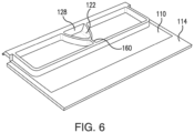
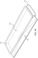
- the debris collection chamber 112 may be formed as part of a tray 113.
- cleaning sheet 114 may be attached to a bottom, surface-facing side, of the tray 113.
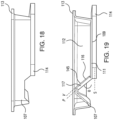
- the bottom, surface-facing side of the tray 113 may include the bottommost surface of the cleaning head 108 (see, e.g., FIG. 19 ).
- an air filter 128 may be attached to a top surface of the tray 113.
- the air filter 128 may form a top wall of the collection chamber 112.
- the collection chamber 112 includes a suction inlet 115 having an inlet opening 116.
- the inlet opening 116 may be located at a top portion of the collection chamber 112.
- the inlet opening 116 may be formed by a top rim 118 of an upwardly extending wall 120.
- the inlet 115 may have a ramp 122 extending from a suction inlet 115, such as a suction nozzle, into the collection chamber 112 to aid in moving debris from the suction inlet 115 into collection areas 126a, 126b of the collection chamber 112.
- the area below the inlet opening 116 may have a floor that is coplanar with a bottom 127 of the collection areas 126a, 126b of the collection chamber 112.
- the inlet opening 116 of the collection chamber 112 may extend along only a portion a length of the cleaning head 108. In some embodiments, the inlet opening 116 may be extend along less than a third of a length of the cleaning head 108. In some embodiments, the inlet opening 116 may be positioned equidistant between first and second lateral (opposite) sides of the cleaning head 108.
- the inlet opening 116 may extend along an entire length of the cleaning head 108. In some embodiments, having an inlet opening 116 that extends along the entire length of the cleaning head 108 may create increased suctioning of debris from the surface to be cleaned.
- the inlet opening 116 may face in a generally upward direction.
- an upward direction means a direction opposite a surface to be cleaned (e.g., away from the cleaning sheet 114) when the cleaning head 108 is placed on a surface.
- debris may travel up and into the debris collection chamber 112 from the suction inlet 115.
- the inlet opening 116 may be substantially parallel to the surface when the cleaning head 108 is placed on the surface.
- a plane P extending through the inlet opening 116 may extend substantially parallel to the surface to be clean.
- the inlet opening 116 also may extend substantially parallel to a plane S extending through a cleaning sheet 114 attached to the tray 113 and to a plane V extending through an internal valve 145 arranged to close the suction inlet 115.
- the plane V extending through the internal valve 145 may be co-planar with the plane P extending through the inlet opening 116.
- the inlet opening 116 may be positioned in a generally upward direction, but may be angled relative to the cleaning sheet 114 (and/or to the surface being cleaned). For example, the inlet opening 116 may be angled between about 25 degrees and about 75 degrees relative to the cleaning sheet 114 (and/or surface to be cleaned).
- the inlet opening 115 may be substantially parallel to an internal valve 145 arranged to close the inlet opening 116 (see the planes labelled P and V) yet be noncoplanar.
- the inlet opening 116 may be formed in a forward wall 117 of the debris collection chamber 112.
- the inlet opening 116 may be reward facing.
- facing rearwardly means that the suction inlet 115 faces in a direction away from a leading edge (e.g., towards a rear) of the cleaning head 108 when the cleaning head is on a surface to be cleaned.
- the inlet opening 116 may face the debris collection chamber 112.
- the inlet opening 116 may be formed in the forward wall 117 of the debris collection chamber 112.
- the inlet opening 116 may be angled relative to the cleaning sheet 114 (and/or to the surface to be cleaned). For example, the inlet opening 116 may be angled between about 75 degrees and 115 degrees relative to the cleaning sheet 114. In some embodiments, the inlet opening 116 may be substantially perpendicular to the cleaning sheet 114 (and/or the surface to be cleaned).
- the collection chamber 112 may have a single collection area.
- the collection area may extend along the entire length of the tray 113, although the collection area may extend along only a portion of the length of the length of the tray 113.
- the collection chamber 112 may include two collection areas 126a and 126b. Each of the collection area 126a and 126b may have similar or dissimilar shape and size with respect to each other.
- collection chamber 112 may have more than three collection areas. In such embodiments, the collection areas may be aligned in rows and/or columns, or may be offset from one another in the tray 113.
- a divider 160 may be provided, such as behind the suction inlet 115 to stiffen the collection chamber 112. In such embodiments, the divider 160 may separate the collection chamber 112 into the collection areas 126a and 126b. The collection chamber need not include such a divider 160. In some embodiments, additional walls similar to the divider 160 may be positioned in the collection chamber 112, in some cases to guide air flow within the collection chamber 112.
- the air filter 128 may be attached to the collection chamber 112, such as to form a top of the collection chamber.
- the air filter 128 may be attached via an elastic connection.
- an elongated strip of elastic material may connect the air filter 128 to a top portion of the collection chamber 112 along a forward wall 117 of the collection chamber 112.
- a similar elongated elastic strip may connect the air filter 128 to the top portion of the collection chamber 112 along the rear wall of the collection chamber 112.
- elastic connectors also may be used on one or both walls at the lateral sides of the collection chamber 112.
- only a portion of the air filter 128 may rise from the collection chamber 112 when negative pressure is applied to the cleaning head 108.
- elastic connectors may be provided along only certain portions of the air filter 128.
- the elastic portions also may be provided in an area of the air inlet opening 116 such that the air filter 128 lifts only in the area of the air filter 128 at or near the air inlet opening 116, while the remaining areas of the air filter 128 are not substantially lifted.
- applying a negative pressure to a collection chamber 112 may include applying a negative pressure to the outside of an air-permeable portion of the collection chamber 112 and/or applying a negative pressure to an opening in the collection chamber 112.
- the air filter 128 may be connected to the collection chamber 112 without any elastic connectors such that the air filter 128 does not move at the connection points.
- the air filter 128 may have a size and shape which allows the air filter 128 to sufficiently lift away from the air inlet opening 116 when under negative pressure such that the air filter 128 lifts away from the air inlet opening 116.
- adhesive strips 123 may be provided on the filter material 128, to secure the filter material to the collection chamber 112, as shown by way of example in FIG. 4 .
- materials other than an air filter 128 may be used to cover the inlet opening 116.
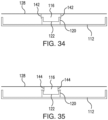
- a section of air-impermeable material may be used in the area of the top wall of the collection chamber 112 as a cover 134 for the inlet opening 116.
- the cover 134 may have the same shape as a perimeter of the chamber inlet opening 116, or it may have a different shape.
- an underside of cover 134 may be provided with an additional material layer.
- a layer of material which conforms easily to the rim 118 forming the suction inlet 115 may be adhered to an underside of the air filter 128. Such a layer may act to seal the inlet opening 116 against passage of debris.
- the cover 134 also may be formed as an additional material layer that is adhered to the underside of an air-filter material used to form the top of the collection chamber 128.
- the portions of the top wall outside of the cover 134 are shown as being an air filter 128 in the embodiment of FIG. 33 , other materials may be used to form the top wall of the collection chamber 112.
- the entire top wall may be air-impermeable, with one or more air filters being provided elsewhere in the arrangement.
- the air-filter material may be limited to specific sections of the collection chamber 112.
- a top chamber wall similarly arranged to the air filter 128 shown in FIG. 33 may have air permeable sections only at or near lateral ends of the top chamber wall, with an air-impermeable material in the remaining section(s).
- air-permeable sections may be positioned close to a centered inlet opening 116.
- Air-permeable sections also may be positioned on one or more sides, such as on both sides, of a centered inlet opening 116.
- One or more inlet openings 116 may be formed in any suitable portion of the collection chamber 112, with air-permeable material in corresponding locations on the top of the collection chamber.
- a collection chamber 112 may include more than one inlet opening 116 and a cover 134 for each of the inlet openings 116.
- the collection chamber 112 may include stiffening ridges 137 along a bottom of the collection chamber 112.
- the stiffening ridges 137 may allow for less material to be used in forming the collection chamber 112.
- the stiffening ridges 137 may extend between the front and back of the collection chamber 112.
- Stiffening ridges 137 may be positioned and sized in any suitable manner.
- stiffening ridges 137 may extend only part way between the front and back of the collection chamber 112.
- Stiffening ridges 137 also may extend at least part way between the lateral sides of the collection chamber 112, or between the sides of the collection areas 126a and 126b.
- the stiffening ridges may extend substantially perpendicular to a suction nozzle 107 of the cleaning head, although they instead may be angled relative to the suction nozzle 107.
- the shape and size of each of the stiffening ridges 137 may be the same as one another, though the shape and size may vary from ridge to ridge.
- Stiffening ribs or grooves also may be used instead of, or in addition to, stiffening ridges 137.
- the same material used in forming the collection chamber 112 may be used to form the stiffening ribs or grooves.
- a different material may be used to form the stiffening ridges 137.
- the collection chamber 112 may be formed via a plastic thermoforming process, although collection chamber 112 may be manufactured using any suitable process.
- the collection chamber 112 may be injection molded or compression molded.
- the collection chamber 112, the suction nozzle 107, and the suction inlet 115 may be formed as a unitary piece (e.g., tray 113).
- the collection chamber 112, the suction nozzle 107, and the suction inlet 115 may be integrally formed, such as by thermoforming.
- one or more of the collection chamber 112, the suction nozzle 107, and the suction inlet 115 may be separately formed and later attached to one another.
- the suction nozzle 107 and suction inlet 115 may be integrally formed, with the collection chamber 112 being separately formed and later attached.
- the suction nozzle 107 may have any suitable arrangement and/or cross-sectional shape.
- at least a portion of the suction nozzle 107 may be curved (see e.g., FIG. 31 ).
- the suction nozzle 107 may have a straight top (see, e.g., FIG. 27 and 31 ).
- the suction nozzle 107 also may include one or more undercuts (see, e.g., FIGS. 19 and 23 ).
- a cleaning sheet 114 may be attached to the collection chamber 112 (e.g., the bottom, surface-facing side of the collection chamber 112) to clean a surface.
- the cleaning sheet 114 may be formed of any suitable material, and may be made of a single layer or multiple layers.
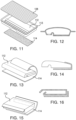
- the cleaning sheet 114 may include multiple layers such as a multifunctional strip 138, a face layer 139, and first and second absorbent layers 140 and 141.
- the face layer 139 and absorbent layers 140 and 141 may be made from various non-woven materials, woven materials, and/or plastics, or any other suitable materials.
- the absorbent layers 140 and 141 may be configured to wick moisture away from the face layer 139.
- the multifunctional strip 138 may be used for scrubbing in some embodiments. In some embodiments, the multifunctional strip 138 may provide friction to help prevent the cleaning device 100 from slipping when propped against a wall.
- the air filter 128 and/or cover 134 may be at least partially spaced from a top surface of the inlet opening 116, the inlet opening 116 may still be closed such that debris may not escape from the collection chamber 112 when the cleaning device 100 is powered down.
- the air filter 128 and/or cover 134 along with the portions that extend into and/or around the outside of the inlet opening 116, may cooperate to close the inlet opening 116 when the cleaning device 100 is powered down.
- the pleated material 129 may be formed of an air-filtering material.
- the top wall of the collection chamber 112 may be formed of an air-impermeable material, and the cleaning device 100 may be configured to encompass at least the top wall and the pleated sides of the pleated material 129.
- the top wall of the collection chamber 112 may be lifted upwardly and away from the inlet opening 116, exposing the air-filtering material of the pleated sides of the pleated material 129. Air may then be withdrawn from the collection chamber 112 via the pleated sides of the pleated material 129.
- the air filter 128 itself may have one or more pleats 130 formed thereon or therein.
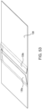
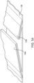
- FIGS. 52-54 show an embodiment of the air filter 128 having two pleats 130, although it may have a fewer or greater number of pleats 130.
- the air filter 128 may be attached to a top surface of a tray 113, or the air filter 128 may form a top wall of the collection chamber 112.
- the air filter 128 may be lifted upward and away from the collection chamber 112.
- the pleats 130 of the air filter 128 may unfold and/or expand. This increases the surface area of the air filter 128 that is exposed to the flow of air, which increases the amount of airborne debris that may be captured.
- the unfolding and/or expanding of the pleats 130 as the air filter 128 lifts upwards and away from the collection chamber 112 effectively increases the volume of the air chamber 112. This may permit more debris to be captured within the debris collection chamber 112.
- FIG. 52 shows an embodiment of an air filter 128 having pleats 130a and 130b.
- the length (i.e., longitudinal dimension) of each pleat 130a and 130b may extend from a first lateral end of the air filter 128 to a second, opposite lateral end of the air filter 128.
- each pleat 130a and/or 130b may terminate a predetermined distance from one or both opposite lateral ends of the air filter 128.
- FIG. 53 shows a cross-sectional view of the air filter show in FIG. 52
- FIG. 54 shows a close-up thereof.
- the interior fold of pleat 130a faces the interior fold of pleat 130b, and the fold of pleat 130a extends further than the fold of pleat 130b.
- the interior folds may be facing the same or opposite directions, and they may be of equal or unequal sizes.
- each pleat 130a and/or pleat 130b may have multiple interior folds.
- the bag may expand from the application of negative pressure such that the portion of the bag covering the inlet opening 116 moves away to allow debris-entrained air to enter the bag.
- walls of the collection chamber 112 may be planar and/or rigid in some embodiments, although the walls, or at least a portion of the walls, may be flexible in other embodiments such that the collection chambers 112 may have a combination of rigid and flexible walls.
- the internal valve 145 may be integrally or attachably formed with at least a portion of the cleaning head 108.
- the internal valve 145 may be integrally formed with or protrude from a top rim 118 of an upwardly extending wall 120 that forms a perimeter of the collection chamber 112.
- the internal valve 145 also may protrude downwardly from the top rim 118 of the upwardly extending wall 120 to block or otherwise obscure the inlet opening 116 when, for example, the cleaning device 100 is powered off.
- the internal valve 145 may be attachably received at an elongated strip or other portion of the air filter 128.
- the internal valve 145 and/or the one or more flaps may be formed of any suitable material, and may be made of a single layer or multiple layers of, for example, non-woven materials, woven materials, and/or plastics, or any other suitable materials.
- the one or more flaps may be glued, heat sealed, or otherwise permanently affixed to each other, the top rim 118, the elongated strip, and/or the air filter 128 to form the internal valve 145.
- the internal valve 145 may be formed of multiple layers including a first layer made of a lightweight, non-woven material and at least a second layer made of a stiff, nonporous material.
- An adhesive strip 123 may be provided on the filter material of the air filter 128 or on the elongated strip protruding downwardly from the air filter 128 to secure the internal valve 145 to the air filter 128.
- the first layer of the internal valve 145 may be heat sealed or otherwise adhered to the adhesive strip 123 provided on the filter material or to an elongated strip of the air filter 128.
- a single fold or pleat may be made in a first layer of the internal valve 145, causing a first side of the first layer to move in a first direction toward the air filter 128 during the manufacturing process.
- the second layer of the internal valve 145 may be heat sealed or otherwise adhered to a second side opposite the first side of the first layer.
- the negative pressure when a negative pressure is applied to or released from the air filter 128, the negative pressure may pull on or release the internal valve 145, causing the internal valve 145 to pivot at the single fold or pleat between an open position when the cleaning device 100 is powered on and a closed position when the cleaning device 100 is powered off.
- the internal valve 145 may be fully sealed against the inlet opening 116 of the suction inlet 115 of the collection chamber 112.
- a frame portion may extend along a perimeter edge of the inlet opening 116 of the suction inlet 115 and be positioned 2 ⁇ 0.5 mm from the perimeter edge of the inlet opening 116.
- the internal valve 145 may rest on the frame portion such that the internal valve 145 is fully sealed against the inlet opening 116 of the suction inlet 115.
- the cleaning sheet 114 may be attached to the collection chamber 112 and be positioned behind the suction nozzle 107 such that debris may be suctioned into the nozzle 107 and collection chamber 112 before reaching the cleaning sheet 114.
- the cleaning sheet 114 includes multiple layers including a multifunctional strip 138, a face layer 139, and first and second absorbent layers 140 and 141.
- the face layer 139 and absorbent layers 140 and 141 may be made from various non-woven materials, woven materials, and/or plastics, or any other suitable materials.
- the absorbent layers 140 and 141 may be configured to wick moisture away from the face layer 139.
- the multifunctional strip 138 may be used for scrubbing a surface in some embodiments.
- the multifunctional strip 138 may provide friction to help prevent the cleaning device 100 from slipping when propped against a wall.
- the debris collection chamber 112 may be permanently or removably attached to the cleaning sheet 114.
- the debris collection chamber 112 when the cleaning head 108 is attached to the cleaning device 100, at least a portion of the debris collection chamber 112 may be concealed.
- the debris collection chamber 112 may be covered by the first connector 106 used to connect the cleaning head 108 to the cleaning device 100.
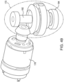
- the cleaning head 108 may be flexibly secured to the body 102 via vertical suspension elements 174 and horizontal suspension elements 176. In such embodiments, the cleaning head 108 may undergo an oscillating motion relative to the body 102 under the influence of a gear drive 172 coupled to a motor 170 mounted to the body 102. As shown in the exemplary embodiment of FIGS. 47 and 49 , a shaft of the motor 170 is disposed horizontally and is coupled to a vertical gear drive 172. The gear drive 172 is in turn coupled to the cleaning head 108 via an offset bearing 194 disposed on a shaft 192 of the gear drive 172. The offset bearing imparts a horizontal oscillating motion to the cleaning head 108 when the motor 170 is powered on.
- FIG. 47 shows two vertical suspension elements 174 near opposite lateral portions of the body 102 and cleaning head 108. There may be a greater or fewer number of vertical suspension elements 174, and the vertical suspension elements 174 may be positioned at various locations instead of or in addition to the illustrated lateral positions.
- FIG. 47 further shows two horizontal suspension elements 176 near front portions of the body 102 and cleaning head 108. There may be a greater or fewer number of horizontal suspension elements 176, and the horizontal suspension elements 176 may be positioned at various locations other than or in addition to the illustrated frontal positions.
- FIG. 48 shows a closeup view of an exemplary vertical suspension element 174.
- This vertical suspension element 174 comprises an upper base 180 mounted to or integrated with the body 102 and a lower base 182 mounted to or integrated with the cleaning head 108.
- a pair of vertical columns 184 couple the upper base 180 to the lower base 182.
- the vertical columns 184 enable the cleaning head 108 to undergo horizontal oscillatory motion relative to the body 102 while maintaining a substantially constant vertical separation between the cleaning head 108 and the body 102.
- the vertical columns 184 may be formed of or comprise a substantially non-compressible compliant material.
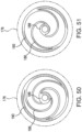
- FIGS. 50-51 show closeup views of exemplary horizontal suspension elements 176.
- Each horizontal suspension element 176 comprises a plurality of arcuate members 186 that extend radially from a substantially central inner hub 188 to a substantially circumferential outer frame 190.
- FIG. 50 shows three arcuate members 186 and
- FIG. 51 shows two arcuate members 186.
- the arcuate members 186 enable the cleaning head 108 to undergo horizontal oscillatory motion while providing a bias to return the cleaning head 108 to a home position relative to the body 102.
- the arcuate members 186 may be formed of or comprise a compliant material.
- the non-return valve may be arranged to keep dust, dry media, and/or wet media within the debris collection chamber 212 once the dirt has been moved into the chamber, such that dust and dry media may be prevented from exiting via a chamber inlet opening of a suction inlet, such as when the cleaning device 100 is powered off.
- the debris collection chamber 212 may be formed as part of a tray 216, which may be constructed of a thermoformed plastic in some embodiments.
- the non-return valve 214 opens when a suction is turned on, and returns to a closed position when the suction is turned off.
- the non-return valve 214 may be formed of a polypropylene.
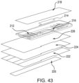
- an air filter 218 covers a top portion of the debris collection chamber 212 .
- the air filter 218 may be made with a hydrophobic material to impede liquid penetration.
- the air filter 218 may be made of a polypropylene.
- a cleaning sheet may be attached to the underside of the tray 216 in some embodiments.
- the cleaning sheet may include one or more layers.
- a multifunctional strip 220 is attached to a face layer 222, which is backed by an acquisition layer 224 and a retention layer 226.
- the multifunctional strip 220 may include a long, narrow piece of material that is attachable to a surface-facing side of the face layer 222.
- the multifunctional strip 220 may be placed on any suitable portion of the face layer 222, although it is shown in FIG. 43 as being located in a central portion of the face layer 222.
- the multifunctional strip 220 may be located in between a forward edge and a rear edge of the face layer 222.
- the multifunctional strip 220 may extend along an entire width of the cleaning sheet, although the strip may extend along only a portion of the width of the cleaning sheet in other embodiments.
- each of the face layer 222, the acquisition layer 224, and the retention layer 226 includes a cutout in a central portion of the front edge of the respective layer. In some embodiments, the cutout is adjacent to a central portion of the suction nozzle 107 when the cleaning sheet is attached to the tray 216.
- the face layer 222 may be made with a hydrophobic material. The hydrophobic material may be arranged such that the weight of the unit puts a pressure on the face layer 222 such that liquid is allowed to penetrate the face layer 222 from surface, but the material is able to help hold acquired liquid within the cleaning sheet.
- the face layer 222 may be treated with paraffin. In some embodiments, the paraffin improves the retention of solid particles on the cleaning sheet when the cleaning sheet is wetted, thereby reducing the potential for redeposit.
- the acquisition layer 224 may be formed of thermal bonded airlaid.
- a density may be used which permits liquid to be absorbed from a surface and desorbed into the retention layer 226.
- the acquisition layer 224 may be formed with a suitable percentage of bi-component to increase mechanical stability and reduce wet collapse.
- the thermal bonded airlaid may be formed with 70% pulp and 30% bi-component.
- the material may be formed with at least 30% of bi-component.
- the multifunctional strip 220 may be formed with hydrophilic meltblown polypropylene in some embodiments. By using a hydrophilic material, the cleaning sheet may provide a more even wipe to reduce streakiness. The multifunctional strip 220 may help to break up stains in some embodiments. Additionally, in some embodiments, by providing a source of friction that is higher than tht of the face layer 222, the multifunctional strip 220 can provide feedback to the user indicating when more liquid as needed.
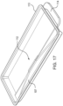
- a debris collection chamber 212 may be constructed and arranged such that bins can be temporarily held together for storage and shipping.
- debris collection chambers 212a and 212b are constructed such that the underside of a first debris collection chamber 212a can be inserted into the top of a second debris collection chamber 212b, and the outsides of the front and rear walls of the first debris collection chamber 212a form an interference fit with the insides of the front and rear walls of the second debris collection chamber 212b.
Landscapes
- Engineering & Computer Science (AREA)
- Mechanical Engineering (AREA)
- Nozzles For Electric Vacuum Cleaners (AREA)
Claims (9)
- Reinigungsvorrichtung, umfassend:einen Vakuumkörper (102), der einen Griff (104) einschließt, der an einen Kopf (106) gekoppelt ist, wobei der Kopf (106) eine untere Basis (182) einschließt;einen austauschbaren Reinigungskopf (108), der ein Reinigungstuch (114) und eine Staubkammer (112) einschließt, wobei der austauschbare Reinigungskopf (108) dazu konfiguriert ist, abnehmbar an der unteren Basis (182) angebracht zu werden, und das Reinigungstuch (114) eine Reinigungsfläche aufweist; undeine Saugkraftquelle, die sich an mindestens einem von dem Körper (102) oder dem austauschbaren Reinigungskopf (108) befindet;dadurch gekennzeichnet, dassdie untere Basis (182) bewegbar an dem Kopf (106) montiert ist;ein Motor (170) mit der unteren Basis (182) verbunden ist, so dass der Motor (170) dazu betreibbar ist, der unteren Basis (182) in Bezug auf den Kopf (106) eine Bewegung zu vermitteln;wobei der austauschbare Reinigungskopf (108), wenn er an der unteren Basis (182) angebracht ist, mit der unteren Basis (182) in Bezug auf den Kopf (106) bewegbar ist.
- Reinigungsvorrichtung nach Anspruch 1, wobei die untere Basis (182) durch mindestens ein flexibles Aufhängeelement (174, 176) mit dem Kopf (106) verbunden ist.
- Reinigungsvorrichtung nach Anspruch 2, wobei die untere Basis (182) durch mindestens zwei flexible Aufhängeelemente (174, 176) mit dem Kopf (106) verbunden ist.
- Reinigungsvorrichtung nach Anspruch 1, wobei der Motor (170) dazu konfiguriert ist, eine Oszillationsbewegung auf die untere Basis (182) zu vermitteln.
- Reinigungsvorrichtung nach Anspruch 4, wobei der Motor (170) mit einer Welle (192) und einem versetzten Lager (194) mit der unteren Basis (182) verbunden ist.
- Reinigungsvorrichtung nach Anspruch 4, wobei die auf die untere Basis (182) vermittelte Oszillationsbewegung in einer Ebene ist, die im Allgemeinen parallel zu der Reinigungsfläche des austauschbaren Reinigungskopfs (108) ist, wenn der austauschbare Reinigungskopf (108) mit dem Kopf (106) verbunden ist.
- Reinigungsvorrichtung nach Anspruch 6, wobei das Reinigungstuch (114) einen Mehrfunktionsstreifen (138) einschließt, der sich auf der Reinigungsfläche des Reinigungstuchs (114) befindet, wobei der Mehrfunktionsstreifen (138) mit dem austauschbaren Reinigungskopf (108) bewegbar ist.
- Reinigungsvorrichtung nach Anspruch 1, wobei die Saugkraftquelle von einem zweiten Motor angetrieben wird, der von dem Motor (170), der die Bewegung der unteren Basis (182) antreibt, separat ist.
- Reinigungsvorrichtung nach Anspruch 1, wobei der austauschbare Reinigungskopf (108) einen Filter (128) einschließt.
Applications Claiming Priority (2)
| Application Number | Priority Date | Filing Date | Title |
|---|---|---|---|
| US201962940237P | 2019-11-25 | 2019-11-25 | |
| PCT/US2020/062158 WO2021108496A1 (en) | 2019-11-25 | 2020-11-25 | Cleaning device |
Publications (3)
| Publication Number | Publication Date |
|---|---|
| EP4064952A1 EP4064952A1 (de) | 2022-10-05 |
| EP4064952A4 EP4064952A4 (de) | 2024-02-21 |
| EP4064952B1 true EP4064952B1 (de) | 2025-07-02 |
Family
ID=75971513
Family Applications (1)
| Application Number | Title | Priority Date | Filing Date |
|---|---|---|---|
| EP20892840.8A Active EP4064952B1 (de) | 2019-11-25 | 2020-11-25 | Reinigungsvorrichtung |
Country Status (3)
| Country | Link |
|---|---|
| US (1) | US20210153705A1 (de) |
| EP (1) | EP4064952B1 (de) |
| WO (1) | WO2021108496A1 (de) |
Families Citing this family (3)
| Publication number | Priority date | Publication date | Assignee | Title |
|---|---|---|---|---|
| EP4209167A1 (de) * | 2022-01-11 | 2023-07-12 | Versuni Holding B.V. | Reinigungskopf und nassreinigungsgerät damit |
| JP7764496B2 (ja) | 2022-01-11 | 2025-11-05 | ヴェルスニ ホールディング ビー ヴィ | 湿式洗浄装置 |
| USD1113019S1 (en) * | 2024-05-31 | 2026-02-10 | Sharkninja Operating Llc | Steam cleaner |
Family Cites Families (11)
| Publication number | Priority date | Publication date | Assignee | Title |
|---|---|---|---|---|
| US7201786B2 (en) * | 2003-12-19 | 2007-04-10 | The Hoover Company | Dust bin and filter for robotic vacuum cleaner |
| JP4612008B2 (ja) * | 2007-03-16 | 2011-01-12 | 三菱電機株式会社 | 電気掃除機 |
| EP2574265B1 (de) * | 2007-05-09 | 2015-10-14 | iRobot Corporation | Kompakter Roboter mit autonomer Reichweite |
| US7934287B2 (en) * | 2008-07-31 | 2011-05-03 | The Procter & Gamble Company | Head for a cleaning implement having a removable dirt bin |
| AU2011244927B2 (en) * | 2010-11-05 | 2014-10-09 | Bissell Inc. | Bare floor vacuum cleaner |
| US9615712B2 (en) * | 2013-11-12 | 2017-04-11 | Irobot Corporation | Mobile floor cleaning robot |
| CA2971610C (en) * | 2014-12-19 | 2023-10-03 | Sharkninja Operating Llc | Vacuum cleaner attachment with floating cleaning element and surface cleaning apparatus including the same |
| US11607095B2 (en) * | 2015-01-30 | 2023-03-21 | Sharkninja Operating Llc | Removable rotatable driven agitator for surface cleaning head |
| EP3991624A1 (de) * | 2017-09-11 | 2022-05-04 | SharkNinja Operating LLC | Reinigungsvorrichtung |
| KR102697035B1 (ko) * | 2018-07-30 | 2024-08-22 | 엘지전자 주식회사 | 청소기의 노즐 및 그 제어방법 |
| KR102418364B1 (ko) * | 2019-08-01 | 2022-07-06 | 산시 지아스다 로봇 테크놀러지 컴퍼니 리미티드 | 진공청소기 브러시 헤드 및 흡진 방법 |
-
2020
- 2020-11-25 US US17/104,229 patent/US20210153705A1/en not_active Abandoned
- 2020-11-25 EP EP20892840.8A patent/EP4064952B1/de active Active
- 2020-11-25 WO PCT/US2020/062158 patent/WO2021108496A1/en not_active Ceased
Also Published As
| Publication number | Publication date |
|---|---|
| EP4064952A4 (de) | 2024-02-21 |
| US20210153705A1 (en) | 2021-05-27 |
| WO2021108496A1 (en) | 2021-06-03 |
| EP4064952A1 (de) | 2022-10-05 |
Similar Documents
| Publication | Publication Date | Title |
|---|---|---|
| US11540686B2 (en) | Cleaning device | |
| EP3873314B1 (de) | Reinigungsvorrichtung | |
| US10966579B2 (en) | Cleaning device | |
| EP4064952B1 (de) | Reinigungsvorrichtung | |
| US20200367706A1 (en) | Cleaning device | |
| US11426044B1 (en) | Cleaning device | |
| HK40023302B (en) | Cleaning device | |
| HK40023302A (en) | Cleaning device |
Legal Events
| Date | Code | Title | Description |
|---|---|---|---|
| STAA | Information on the status of an ep patent application or granted ep patent |
Free format text: STATUS: THE INTERNATIONAL PUBLICATION HAS BEEN MADE |
|
| PUAI | Public reference made under article 153(3) epc to a published international application that has entered the european phase |
Free format text: ORIGINAL CODE: 0009012 |
|
| STAA | Information on the status of an ep patent application or granted ep patent |
Free format text: STATUS: REQUEST FOR EXAMINATION WAS MADE |
|
| 17P | Request for examination filed |
Effective date: 20220510 |
|
| AK | Designated contracting states |
Kind code of ref document: A1 Designated state(s): AL AT BE BG CH CY CZ DE DK EE ES FI FR GB GR HR HU IE IS IT LI LT LU LV MC MK MT NL NO PL PT RO RS SE SI SK SM TR |
|
| DAV | Request for validation of the european patent (deleted) | ||
| DAX | Request for extension of the european patent (deleted) | ||
| RIC1 | Information provided on ipc code assigned before grant |
Ipc: A47L 9/06 20060101ALI20231011BHEP Ipc: A47L 9/04 20060101ALI20231011BHEP Ipc: A47L 9/00 20060101ALI20231011BHEP Ipc: A47L 9/16 20060101ALI20231011BHEP Ipc: A47L 9/14 20060101ALI20231011BHEP Ipc: A47L 9/10 20060101ALI20231011BHEP Ipc: A47L 9/02 20060101ALI20231011BHEP Ipc: A47L 5/28 20060101ALI20231011BHEP Ipc: A47L 11/40 20060101AFI20231011BHEP |
|
| P01 | Opt-out of the competence of the unified patent court (upc) registered |
Effective date: 20231020 |
|
| A4 | Supplementary search report drawn up and despatched |
Effective date: 20240123 |
|
| RIC1 | Information provided on ipc code assigned before grant |
Ipc: A47L 9/06 20060101ALI20240117BHEP Ipc: A47L 9/04 20060101ALI20240117BHEP Ipc: A47L 9/00 20060101ALI20240117BHEP Ipc: A47L 9/16 20060101ALI20240117BHEP Ipc: A47L 9/14 20060101ALI20240117BHEP Ipc: A47L 9/10 20060101ALI20240117BHEP Ipc: A47L 9/02 20060101ALI20240117BHEP Ipc: A47L 5/28 20060101ALI20240117BHEP Ipc: A47L 11/40 20060101AFI20240117BHEP |
|
| GRAP | Despatch of communication of intention to grant a patent |
Free format text: ORIGINAL CODE: EPIDOSNIGR1 |
|
| STAA | Information on the status of an ep patent application or granted ep patent |
Free format text: STATUS: GRANT OF PATENT IS INTENDED |
|
| INTG | Intention to grant announced |
Effective date: 20250128 |
|
| GRAS | Grant fee paid |
Free format text: ORIGINAL CODE: EPIDOSNIGR3 |
|
| GRAA | (expected) grant |
Free format text: ORIGINAL CODE: 0009210 |
|
| STAA | Information on the status of an ep patent application or granted ep patent |
Free format text: STATUS: THE PATENT HAS BEEN GRANTED |
|
| AK | Designated contracting states |
Kind code of ref document: B1 Designated state(s): AL AT BE BG CH CY CZ DE DK EE ES FI FR GB GR HR HU IE IS IT LI LT LU LV MC MK MT NL NO PL PT RO RS SE SI SK SM TR |
|
| REG | Reference to a national code |
Ref country code: GB Ref legal event code: FG4D |
|
| REG | Reference to a national code |
Ref country code: CH Ref legal event code: EP |
|
| REG | Reference to a national code |
Ref country code: DE Ref legal event code: R096 Ref document number: 602020054003 Country of ref document: DE |
|
| REG | Reference to a national code |
Ref country code: IE Ref legal event code: FG4D |
|
| REG | Reference to a national code |
Ref country code: NL Ref legal event code: MP Effective date: 20250702 |
|
| PG25 | Lapsed in a contracting state [announced via postgrant information from national office to epo] |
Ref country code: PT Free format text: LAPSE BECAUSE OF FAILURE TO SUBMIT A TRANSLATION OF THE DESCRIPTION OR TO PAY THE FEE WITHIN THE PRESCRIBED TIME-LIMIT Effective date: 20251103 |
|
| PG25 | Lapsed in a contracting state [announced via postgrant information from national office to epo] |
Ref country code: NL Free format text: LAPSE BECAUSE OF FAILURE TO SUBMIT A TRANSLATION OF THE DESCRIPTION OR TO PAY THE FEE WITHIN THE PRESCRIBED TIME-LIMIT Effective date: 20250702 |
|
| REG | Reference to a national code |
Ref country code: AT Ref legal event code: MK05 Ref document number: 1808253 Country of ref document: AT Kind code of ref document: T Effective date: 20250702 |
|
| PG25 | Lapsed in a contracting state [announced via postgrant information from national office to epo] |
Ref country code: IS Free format text: LAPSE BECAUSE OF FAILURE TO SUBMIT A TRANSLATION OF THE DESCRIPTION OR TO PAY THE FEE WITHIN THE PRESCRIBED TIME-LIMIT Effective date: 20251102 |
|
| PG25 | Lapsed in a contracting state [announced via postgrant information from national office to epo] |
Ref country code: NO Free format text: LAPSE BECAUSE OF FAILURE TO SUBMIT A TRANSLATION OF THE DESCRIPTION OR TO PAY THE FEE WITHIN THE PRESCRIBED TIME-LIMIT Effective date: 20251002 |
|
| REG | Reference to a national code |
Ref country code: LT Ref legal event code: MG9D |
|
| PG25 | Lapsed in a contracting state [announced via postgrant information from national office to epo] |
Ref country code: AT Free format text: LAPSE BECAUSE OF FAILURE TO SUBMIT A TRANSLATION OF THE DESCRIPTION OR TO PAY THE FEE WITHIN THE PRESCRIBED TIME-LIMIT Effective date: 20250702 |
|
| PG25 | Lapsed in a contracting state [announced via postgrant information from national office to epo] |
Ref country code: FI Free format text: LAPSE BECAUSE OF FAILURE TO SUBMIT A TRANSLATION OF THE DESCRIPTION OR TO PAY THE FEE WITHIN THE PRESCRIBED TIME-LIMIT Effective date: 20250702 |
|
| PG25 | Lapsed in a contracting state [announced via postgrant information from national office to epo] |
Ref country code: HR Free format text: LAPSE BECAUSE OF FAILURE TO SUBMIT A TRANSLATION OF THE DESCRIPTION OR TO PAY THE FEE WITHIN THE PRESCRIBED TIME-LIMIT Effective date: 20250702 |
|
| PG25 | Lapsed in a contracting state [announced via postgrant information from national office to epo] |
Ref country code: GR Free format text: LAPSE BECAUSE OF FAILURE TO SUBMIT A TRANSLATION OF THE DESCRIPTION OR TO PAY THE FEE WITHIN THE PRESCRIBED TIME-LIMIT Effective date: 20251003 |
|
| PG25 | Lapsed in a contracting state [announced via postgrant information from national office to epo] |
Ref country code: SE Free format text: LAPSE BECAUSE OF FAILURE TO SUBMIT A TRANSLATION OF THE DESCRIPTION OR TO PAY THE FEE WITHIN THE PRESCRIBED TIME-LIMIT Effective date: 20250702 Ref country code: CZ Free format text: LAPSE BECAUSE OF FAILURE TO SUBMIT A TRANSLATION OF THE DESCRIPTION OR TO PAY THE FEE WITHIN THE PRESCRIBED TIME-LIMIT Effective date: 20250702 |
|
| PG25 | Lapsed in a contracting state [announced via postgrant information from national office to epo] |
Ref country code: LV Free format text: LAPSE BECAUSE OF FAILURE TO SUBMIT A TRANSLATION OF THE DESCRIPTION OR TO PAY THE FEE WITHIN THE PRESCRIBED TIME-LIMIT Effective date: 20250702 |
|
| PG25 | Lapsed in a contracting state [announced via postgrant information from national office to epo] |
Ref country code: PL Free format text: LAPSE BECAUSE OF FAILURE TO SUBMIT A TRANSLATION OF THE DESCRIPTION OR TO PAY THE FEE WITHIN THE PRESCRIBED TIME-LIMIT Effective date: 20250702 Ref country code: BG Free format text: LAPSE BECAUSE OF FAILURE TO SUBMIT A TRANSLATION OF THE DESCRIPTION OR TO PAY THE FEE WITHIN THE PRESCRIBED TIME-LIMIT Effective date: 20250702 |
|
| PG25 | Lapsed in a contracting state [announced via postgrant information from national office to epo] |
Ref country code: RS Free format text: LAPSE BECAUSE OF FAILURE TO SUBMIT A TRANSLATION OF THE DESCRIPTION OR TO PAY THE FEE WITHIN THE PRESCRIBED TIME-LIMIT Effective date: 20251002 |
|
| PG25 | Lapsed in a contracting state [announced via postgrant information from national office to epo] |
Ref country code: ES Free format text: LAPSE BECAUSE OF FAILURE TO SUBMIT A TRANSLATION OF THE DESCRIPTION OR TO PAY THE FEE WITHIN THE PRESCRIBED TIME-LIMIT Effective date: 20250702 |
|
| PG25 | Lapsed in a contracting state [announced via postgrant information from national office to epo] |
Ref country code: RO Free format text: LAPSE BECAUSE OF FAILURE TO SUBMIT A TRANSLATION OF THE DESCRIPTION OR TO PAY THE FEE WITHIN THE PRESCRIBED TIME-LIMIT Effective date: 20250702 |
|
| PG25 | Lapsed in a contracting state [announced via postgrant information from national office to epo] |
Ref country code: SM Free format text: LAPSE BECAUSE OF FAILURE TO SUBMIT A TRANSLATION OF THE DESCRIPTION OR TO PAY THE FEE WITHIN THE PRESCRIBED TIME-LIMIT Effective date: 20250702 |
|
| PG25 | Lapsed in a contracting state [announced via postgrant information from national office to epo] |
Ref country code: DK Free format text: LAPSE BECAUSE OF FAILURE TO SUBMIT A TRANSLATION OF THE DESCRIPTION OR TO PAY THE FEE WITHIN THE PRESCRIBED TIME-LIMIT Effective date: 20250702 |
|
| PG25 | Lapsed in a contracting state [announced via postgrant information from national office to epo] |
Ref country code: IT Free format text: LAPSE BECAUSE OF FAILURE TO SUBMIT A TRANSLATION OF THE DESCRIPTION OR TO PAY THE FEE WITHIN THE PRESCRIBED TIME-LIMIT Effective date: 20250702 |
|
| PG25 | Lapsed in a contracting state [announced via postgrant information from national office to epo] |
Ref country code: EE Free format text: LAPSE BECAUSE OF FAILURE TO SUBMIT A TRANSLATION OF THE DESCRIPTION OR TO PAY THE FEE WITHIN THE PRESCRIBED TIME-LIMIT Effective date: 20250702 Ref country code: SK Free format text: LAPSE BECAUSE OF FAILURE TO SUBMIT A TRANSLATION OF THE DESCRIPTION OR TO PAY THE FEE WITHIN THE PRESCRIBED TIME-LIMIT Effective date: 20250702 |