EP4064812B1 - Electromagnetic shield structure and wire harness - Google Patents
Electromagnetic shield structure and wire harness Download PDFInfo
- Publication number
- EP4064812B1 EP4064812B1 EP22174572.2A EP22174572A EP4064812B1 EP 4064812 B1 EP4064812 B1 EP 4064812B1 EP 22174572 A EP22174572 A EP 22174572A EP 4064812 B1 EP4064812 B1 EP 4064812B1
- Authority
- EP
- European Patent Office
- Prior art keywords
- electromagnetic shield
- braided wire
- shield pipe
- braided
- cable
- Prior art date
- Legal status (The legal status is an assumption and is not a legal conclusion. Google has not performed a legal analysis and makes no representation as to the accuracy of the status listed.)
- Active
Links
Images








Classifications
-
- H—ELECTRICITY
- H05—ELECTRIC TECHNIQUES NOT OTHERWISE PROVIDED FOR
- H05K—PRINTED CIRCUITS; CASINGS OR CONSTRUCTIONAL DETAILS OF ELECTRIC APPARATUS; MANUFACTURE OF ASSEMBLAGES OF ELECTRICAL COMPONENTS
- H05K9/00—Screening of apparatus or components against electric or magnetic fields
- H05K9/0073—Shielding materials
- H05K9/0098—Shielding materials for shielding electrical cables
-
- H—ELECTRICITY
- H01—ELECTRIC ELEMENTS
- H01B—CABLES; CONDUCTORS; INSULATORS; SELECTION OF MATERIALS FOR THEIR CONDUCTIVE, INSULATING OR DIELECTRIC PROPERTIES
- H01B7/00—Insulated conductors or cables characterised by their form
- H01B7/0045—Cable-harnesses
-
- H—ELECTRICITY
- H02—GENERATION; CONVERSION OR DISTRIBUTION OF ELECTRIC POWER
- H02G—INSTALLATION OF ELECTRIC CABLES OR LINES, OR OF COMBINED OPTICAL AND ELECTRIC CABLES OR LINES
- H02G15/00—Cable fittings
- H02G15/08—Cable junctions
- H02G15/10—Cable junctions protected by boxes, e.g. by distribution, connection or junction boxes
- H02G15/103—Cable junctions protected by boxes, e.g. by distribution, connection or junction boxes with devices for relieving electrical stress
- H02G15/105—Cable junctions protected by boxes, e.g. by distribution, connection or junction boxes with devices for relieving electrical stress connected to the cable shield only
-
- H—ELECTRICITY
- H02—GENERATION; CONVERSION OR DISTRIBUTION OF ELECTRIC POWER
- H02G—INSTALLATION OF ELECTRIC CABLES OR LINES, OR OF COMBINED OPTICAL AND ELECTRIC CABLES OR LINES
- H02G3/00—Installations of electric cables or lines or protective tubing therefor in or on buildings, equivalent structures or vehicles
- H02G3/02—Details
- H02G3/04—Protective tubing or conduits, e.g. cable ladders or cable troughs
- H02G3/0462—Tubings, i.e. having a closed section
- H02G3/0481—Tubings, i.e. having a closed section with a circular cross-section
-
- B—PERFORMING OPERATIONS; TRANSPORTING
- B60—VEHICLES IN GENERAL
- B60R—VEHICLES, VEHICLE FITTINGS, OR VEHICLE PARTS, NOT OTHERWISE PROVIDED FOR
- B60R16/00—Electric or fluid circuits specially adapted for vehicles and not otherwise provided for; Arrangement of elements of electric or fluid circuits specially adapted for vehicles and not otherwise provided for
- B60R16/02—Electric or fluid circuits specially adapted for vehicles and not otherwise provided for; Arrangement of elements of electric or fluid circuits specially adapted for vehicles and not otherwise provided for electric constitutive elements
- B60R16/0207—Wire harnesses
- B60R16/0215—Protecting, fastening and routing means therefor
Definitions
- the present invention relates to an electromagnetic shield structure including a cable laid inside and used for an electric vehicle, for example.
- an electromagnetic shield pipe such as a metallic pipe or a composite pipe composed of a metallic layer and a resin layer is used as a protective pipe of a cable. Influence on the outside caused by noise that is generated from a cable inside or influence on the cable inside caused by noise on the outside can be suppressed by storing the cable in the electromagnetic shield pipe.
- a plurality of cables such as a high-voltage electric wire for connecting a high-voltage battery and an inverter and a low-voltage electric wire for connecting a low-voltage battery and a relay box is stored in one electromagnetic shield pipe.
- noise from the high-voltage electric wire is shielded so as not to be transmitted to the low-voltage electric wire in the interior of the electromagnetic shield pipe.
- a shielding member e.g., braided wire
- this electromagnetic shield structure for example, there is a method in which a braided wire into which the high-voltage electric wire is inserted and a braided wire into which the low-voltage electric wire is inserted are overlapped, and crimped with a crimp member such as a ring on a metallic portion (conductive portion) such as an end of an electromagnetic shield pipe (Patent Document 1).
- Patent document 2 discloses an electromagnetic shield structure according to the preamble of claim 1.
- Patent document 3 discloses a cable shielding which has two halves such that there is no overlap over the shielding layers.
- the present invention has been made in view of these problems, and it is an object of the present invention to provide an electromagnetic shield structure capable of securing a stable energizing state between a flexible shield member and an electromagnetic shield pipe and maintaining the holding strength of the flexible shield member for the long term.
- the present invention provides an electromagnetic shield structure according to claim 1 and a wire harness according to claim 2.
- an electromagnetic shield structure that is capable of securing a stable energizing state between the flexible shield member and the electromagnetic shield pipe and maintaining the holding strength of the flexible shield member for the long term, can be provided.
- the metal layer 7 may be made of aluminum (including an aluminum alloy).
- the outer layer 5 of the electromagnetic shield pipe 3 is peeled off by a predetermined length from an end portion. That is, the metal layer 7 is exposed only by a predetermined range on the end portion of the electromagnetic shield pipe 3.
- the exposed metal layer 7 serves as a connection portion connected to a cylindrical flexible shield member described later.
- a cable 9a being a first cable and a cable 9b being a second cable are inserted into the electromagnetic shield pipe 3 and exposed from the end portion of the electromagnetic shield pipe 3. That is, a plurality of cables is inserted into the interior of the electromagnetic shield pipe 3.
- the cable 9a is, for example, a high-voltage cable
- the cable 9b is, for example, a low-voltage cable.
- the cylindrical flexible shield member a cylindrical braided wire in which a plated copper wire is braided is preferably used, and in the description below, an explanation is given by exemplifying a cylindrical braided wire as the cylindrical flexible shield member. Needless to say, the cylindrical flexible shield member is not limited to the cylindrical braided wire.
- Fig. 1b is a side view of the electromagnetic shield structure 1 provided on the electromagnetic shield pipe 3.
- the electromagnetic shield structure 1 includes the electromagnetic shield pipe 3, the cables 9a and 9b, and braided wires 11a and 11b.
- the cylindrical braided wire 11a that is a first cylindrical flexible shield member covers the cable 9a exposed from the end portion of the electromagnetic shield pipe 3.
- the cylindrical braided wire 11b that is a second cylindrical flexible shield member covers the cable 9b exposed from the end portion of the electromagnetic shield pipe 3.
- terminals (not illustrated) are connected to the end portions of the plurality of cables 9a and 9b, and used as a wire harness 20.
- Fig. 2a is a plan view of the end portion of the braided wire 11b that covers the cable 9b and a view viewed from the direction of an arrow B of Fig. 2b.
- Fig. 2b is a side view of the end portion of the braided wire 11b that covers the cable 9b and a view viewed from the direction of an arrow A of Fig. 2a .
- the braided wire 11a for the cable 9a has similar form, and thus the illustration thereof will be omitted.
- the cylindrical shape of the end portions (the end portions on the electromagnetic shield pipe 3 side) of the braided wires 11a and 11b is loosened and expanded. That is, the end portions of the braided wires 11a and 11b are formed in a sheet-like shape.
- a sheet-like portion of the end portion of the braided wire 11a is a sheet-like portion 15a.
- a sheet-like portion of the end portion of the braided wire 11b is a sheet-like portion 15b.
- the sheet-like portion 15a of the end portion of the braided wire 11a is crimped by a crimp member 13 on an exposed portion of the metal layer 7 of the end portion of the electromagnetic shield pipe 3.
- the sheet-like portion 15b of the end portion of the braided wire 11b is crimped by the same crimp member 13 on the exposed portion of the metal layer 7 of the end portion of the electromagnetic shield pipe 3. That is, the braided wire 11a and the braided wire 11b are fixed with the crimp member 13 on the outer circumference of the electromagnetic shield pipe 3 at the same position in the longitudinal direction of the electromagnetic shield pipe 3.
- Fig. 3a is a cross-sectional view of a portion perpendicular to the longitudinal direction of the electromagnetic shield pipe 3 where the crimp member 13 is disposed.
- the braided wire 11a (the sheet-like portion 15a) and the braided wire 11b (the sheet-like portion 15b) are fixed with the crimp member 13 at different positions in the circumferential direction on the cross section perpendicular to the longitudinal direction of the electromagnetic shield pipe 3.
- the braided wire 11a is fixed in a substantially semicircle on a lower side in the circumferential direction of the electromagnetic shield pipe 3
- the braided wire 11b is fixed in another substantially semicircle (upper side in the diagram) in the circumferential direction of the electromagnetic shield pipe 3.
- each of the sheet-like portion 15a of the braided wire 11a and the sheet-like portion 15b of the braided wire 11b is not required to be fixed in a substantially semicircle in the circumferential direction of the electromagnetic shield pipe 3.
- the width of the sheet-like portion 15a may be wider than the width of the sheet-like portion 15b.
- the cylindrical end portions of the braided wires 11a and 11b are loosened, and each of the sheet-like portions 15a and 15b is formed on the end portion.
- the sheet-like portions 15a and 15b of the end portions of the braided wires 11a and 11b are disposed at different positions in the circumferential direction of the electromagnetic shield pipe 3 and fixed on the metal layer 7 of the electromagnetic shield pipe 3 with the crimp member 13.
- the braided wires 11a and 11b in a portion crimped by the crimp member 13 are fixed without being overlapped with each other in the circumferential direction of the electromagnetic shield pipe 3.
- each of the plurality of braided wires 11a and 11b is fixed with the crimp member 13 on the outer circumference of the electromagnetic shield pipe 3.
- the entire outer circumferential surface of each of the plurality of braided wires 11a and 11b is pressed by the crimp member 13 from the outer circumferential side, in the portion where the crimp member 13 is disposed on the cross section perpendicular to the longitudinal direction of the electromagnetic shield pipe 3. That is, the portion where the crimp member 13 is disposed in the longitudinal direction of the electromagnetic shield pipe 3 serves as a crimp portion where the braided wires 11a and 11b are pressed from the outer circumference.
- each of the entire outer circumferential surfaces is pressed by the crimp member 13 from the outer circumferential side means that the entire outer circumferential surfaces of all the braided wires 11a and 11b are directly or indirectly pressed by the crimp member 13 from the outer circumferential side.
- a section to which pressing force generated by tightening by the crimp member 13 from the outer circumferential side is not transmitted occurs in a part of any of the braided wires 11a and 11b on both sides of the step. In the present invention, the section to which this pressing force is not transmitted does not occur.
- no gap occurs between the part of the outer circumferential surface of the braided wires 11a and 11b and the crimp member 13 disposed on the outer circumferential side of the braided wires 11a and 11b (or another member disposed between the crimp member 13 and each braided 10 wire).
- the entire outer circumferential surface of the braided wires 11a and 11b is adhered to members disposed on the outer circumferential side of the braided wires 11a and 11b.
- this "gap" does not include a minuscule gap caused by depressions and recesses on the outer surface of the braided wires 11a and 11b between the braided wires and the crimp member 13 or the like.
- the thicknesses of the sheet-like portions 15a and 15b in the portion where the crimp member 13 is disposed are substantially equal.
- the number of cables inserted into the electromagnetic shield pipe 3 is not limited to two.
- the cables 9a and 9b may be not one, but may be a plurality. Even in this case, the cables 9a and 9b exposed from the electromagnetic shield pipe 3 are respectively covered with the braided wires 11a and 11b and, the braided wires 11a and 11b are crimped at different positions in the circumferential direction.
- the plurality of cables may be inserted into one braided wire, or different braided wire may be used for each cable. Even in this case, respective braided wires are disposed not to be overlapped with each other in a crimp portion.
- the cable 9a is a high-voltage system cable
- the cable 9b is a low-voltage system cable
- the high-voltage system cables and the low-voltage system cables are inserted into the braided wire for each system, thereby achieving shielding between the high-voltage system cables and the low-voltage system cables, between the electromagnetic shield pipe 3 and a connector.
- the cables inserted into the electromagnetic shield pipe 3 are not limited to the two systems of the cables 9a and 9b.
- the cables inserted into the electromagnetic shield pipe 3 are three or more systems, or when a three-phase alternating current wire is provided, three or more braided wires may be used, and the sheet-like portions of the end portions of respective braided wires are only required to be disposed in such a manner so as not to be overlapped with each other at different positions in the circumferential direction of the electromagnetic shield pipe 3.
- the circumferential length of the sheet-like portions 15a, 15b, and 15c may be substantially equally divided and disposed in such a manner so as to be one third of the length of the circumferential direction.
- the sheet-like portions 15a, 15b, and 15c may be disposed in such a manner that the lengths of the circumferential direction are different from each other.
- the thicknesses of the sheet-like portions 15a, 15b, and 15c in the portion where the crimp member 13 is disposed are substantially equal.
- the metal layer 7 of the end portion of the electromagnetic shield pipe 3 is exposed.
- the cables 9a and 9b are inserted into the electromagnetic shield pipe 3.
- a braided wire may be disposed on the outer circumference of the cable 9a or the cable 9b in the interior of the electromagnetic shield pipe 3.
- the cable 9a exposed from the electromagnetic shield pipe 3 is covered with the braided wire 11a.
- the cylindrical portion of the end portion of the braided wire 11a (on the electromagnetic shield pipe 3 side) is loosened, and the sheet-like portion 15a having a predetermined length is formed.
- the cable 9b exposed from the electromagnetic shield pipe 3 is covered with the braided wire 11b.
- the cylindrical portion of the end portion of the braided wire 11b (on the electromagnetic shield pipe 3 side) is loosened, and the sheet-like portion 15b having a predetermined length is formed.
- the sheet-like portions 15a and 15b of the end portions of the braided wires 11a and 11b are disposed on the outer circumference of the metal layer 7.
- the sheet-like portions 15a and 15b are disposed at different positions in the circumferential direction of the electromagnetic shield pipe 3 so as not to be overlapped with each other.
- the braided wires 11a and 11b are crimped and fixed with the crimp member 13 on the electromagnetic shield pipe 3.
- the end portion (crimp portion) of the electromagnetic shield pipe 3 is covered with a rubber member or the like as appropriate.
- the electromagnetic shield structure 1 is formed.
- the braided wires 11a and 11b are crimped without being overlapped with each other at different positions in the circumferential direction of the electromagnetic shield pipe 3 in the crimp portion.
- the crimp member 13 is disposed, the entire outer circumferential surface of each of the braided wires 11a and 11b is pressed by the crimp member 13 from the outer circumferential side, and the stable holding strength by the crimp member 13 can be secured.
- the braided wires 11a and 11b are respectively disposed in substantially semicircles in the circumferential direction of the electromagnetic shield pipe 3, thereby respectively securing a sufficient contact area.
- Figs. 6a and 6b are views illustrating processes for forming an electromagnetic shield structure according to the Second Embodiment, and Fig. 6a is a side view, and Fig. 6b is a plan view. Note that, in the description below, constituent elements which have the same effect will be assigned the same reference numerals as in Fig. 1b and other drawings, and redundant descriptions of those constituent elements will be omitted.
- the cable 9a exposed from the electromagnetic shield pipe 3 is inserted into the braided wire 11a.
- the end portion of the braided wire 11a covers the end portion (the metal layer 7) of the electromagnetic shield pipe 3 while being formed in a cylindrical shape.
- the stitches of the braided wire 11a can be easily expanded, so that the diameter of the cylinder can be easily increased while the cylindrical shape is maintained.
- the end portion of the braided wire 11a can be expanded to cover the outer circumference of the electromagnetic shield pipe 3.
- the holes 17a and 19 are formed in part of the braided wire 11a. Note that the hole 17a and the hole 19 are formed in the substantially same direction as the circumferential direction of the braided wire 11a.
- the holes 17a and 19 are formed by expanding the metallic elemental wires of the braided wire 11a to 35 both sides.
- the hole 17a is formed on the base portion side of the braided wire 11a with respect to a portion that covers the electromagnetic shield pipe 3.
- the hole 17a is a portion penetrated by the cable 9b.
- the hole 19 is formed on the end portion side of the braided wire 11a with respect to the hole 17a. That is, the hole 19 is formed in a portion of the braided wire 11a, the portion that covers the electromagnetic shield pipe 3. More specifically, as illustrated, the braided wire 11a covers the end portion of the electromagnetic shield pipe 3 in such a manner so that the hole 19 is positioned at the metal layer 7. Note that the hole 17a and the hole 19 may communicate with each other.
- Fig. 7a and Fig. 7b are views illustrating a state where the cable 9b is further covered with the braided wire 11b, and Fig. 7a is a side view, and Fig. 7b is a plan view.
- the sheet-like portion 15b is formed in the end portion of the braided wire 11b. That is, the cylindrical braided wire 11b is disposed on the cable 9b exposed from the braided wire 11a, and the sheet-like portion 15b is disposed so as to be overlapped with the braided wire 11a.
- part of the sheet-like portion 15b is overlapped at a position of the hole 19 of the braided wire 11a.
- a part of the sheet-like portion 15b is disposed so as to cover the metal layer 7 exposed from the hole 19.
- the width of the braided wire 11b is narrower that the width of the hole 19. This prevents the braided wire 11b from protruding from the hole 19 and from being overlapped with the braided wire 11a in the circumferential direction of the hole 19.
- Fig. 8 is a view illustrating an electromagnetic shield structure 1a in which the braided wires 11a and 11b are fixed with the crimp member 13
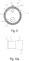
- Fig. 9 is a cross-sectional view of a portion where the crimp member 13 is disposed. As illustrated, the braided wires 11a and 11b are fixed with the crimp member 13 on the electromagnetic shield pipe 3 in the portion where the crimp member 13 is disposed, corresponding to the hole 19.
- the end portion of the braided wire 11a covers the outer circumference of the electromagnetic shield pipe 3 while being in a cylindrical shape.
- the hole 19 is provided in part of the braided wire 11a positioned on the outer circumference of the electromagnetic shield pipe 3, and the sheet-like portion 15b of the end portion of the braided wire 1 1b covers the position of the hole 19.
- the braided wires 11a and 11b are fixed with the crimp member 13 on the electromagnetic shield pipe 3 in a portion in the circumferential direction corresponding to the hole 19. This prevents the braided wires 11a and 11b from being partially overlapped with the outer circumference of the electromagnetic shield pipe 3 in the crimp portion.
- the same effect as that of the First Embodiment can be achieved. That is, by removing the partial overlapping of the braided wires 11a and 11b in the crimp portion, the entire outer circumferential surface of each of the braided wires 11a and 11b is pressed by the crimp member 13 from the outer circumferential side, and the stability of holding strength or the stability of an energized state can be obtained.
- the hole 19 is provided in the braided wire 11a, which makes it unnecessary to loosen the end portion of the braided wire 11a and form the sheet-like portion 15a.
- the braided wires 11a and 1 1b can be appropriately disposed by adjusting the size of the hole 19 in such a manner as to cover each of substantially semicircles of the electromagnetic shield pipe 3.
- the thickness of the braided wire 11a and the thickness of the sheet-like portion 15b in the portion where the crimp member 13 is disposed are substantially equal.
- Fig. 10a is a side view illustrating an electromagnetic shield pipe 3
- Fig. 10b is a side view illustrating an electromagnetic shield structure 1b according to the Third Embodiment.
- Fig. 10b is a perspective view of the braided wires 11a and 1 1b, and the illustration of cables is omitted.
- the outer layer 5 in the vicinity of the end portion of the electromagnetic shield pipe 3 is not entirely removed, but the outer layer 5 remains in an annular shape in part of the tip end portion. That is, the exposed portion of the metal layer 7 is caught by the outer layers 5 and formed in an annular shape.
- the braided wires 11a and 11b are crimped by the crimp member 13 on the metal layer 7 in such a manner that the braided wires 11a and 11b are not overlapped with each other.
- the braided wires 11a and 11b steadily comes in contact with the metal layer 7, which leads to electrical conduction.
- the arrangement of the braided wires 11a and 11b can have any form as long as the partial overlapping is eliminated.
- the annular outer layer 5 on the tip end side is positioned on the tip end side with respect to a crimping position of the crimp member 13.
- the outer layer 5 has a larger outer diameter than that of the exposed portion of the metal layer 7.
- a large diameter portion formed by the annular outer layer 5 is provided on the tip end side of the crimping position of the crimp member 13 with respect to the electromagnetic shield pipe 3.
- the same effect as that of the First Embodiment can be achieved. That is, by removing the partial overlapping of the braided wires 11a and 11b in the portion where the crimp member 13 is disposed, the entire outer circumferential surface of each of the braided wires 11a and 11b is pressed by the crimp member 13 from the outer circumferential side, and the stability of holding strength or the stability of an energized state can be obtained.
- the thicknesses of the sheet-like portions 15a and 15b in the portion where the crimp member 13 is disposed are substantially equal.
- the outer layer 5 provided in an annular form functions as a stopper for preventing the crimp member 13 from coming off, so that the outer layer 5 can prevent the crimp member 13 from coming off from the electromagnetic shield pipe 3.
- another member such as resin may be adhered to the outer circumferential portion of the metal layer 7 in an annular form, thereby forming a large diameter portion on the tip end side of the crimping position.
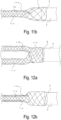
- Fig. 11a and Fig. 11b are views illustrating processes for forming an electromagnetic shield structure according to the Fourth Embodiment, and Fig. 11a is a side view, and Fig. 11b is a plan view.
- the cable 9a exposed from the electromagnetic shield pipe 3 is inserted into the braided wire 11a.
- the outer layer 5 may be provided on the tip end portion of the electromagnetic shield pipe 3.
- the end portion of the braided wire 11a covers the end portion (the metal layer 7) of the electromagnetic shield pipe 3 while being in a cylindrical shape.
- the hole 17a is formed in part of the braided wire 11a. As described above, the hole 17a is a portion penetrated by the cable 9b. Thus, when the cable 9a is inserted into the braided wire 11a, the cable 9b is also inserted into the braided wire 11a and taken out from the hole 17a to the outside. Note that 20 the hole 17a may be formed by opening the cylindrical shape of the braided wire 11a.
- Fig. 12a and Fig. 12b are views illustrating a state where the cable 9b is covered with the braided wire 11b, and Fig. 12a is a side view, and Fig. 12b is a plan view.
- the sheet-like portion 15b is not formed at the end portion of the braided wire 11b which is in a cylindrical shape.
- a hole 17b penetrated by the braided wire 11a (the cable 9a) is formed in the braided wire 11b. Note that the hole 17b may be formed by opening the cylindrical shape of the braided wire 11b.
- both the braided wire 11a (the cable 9a) and the cable 9b are inserted from the end portion of the braided wire 11b, and only the braided wire 11a (the cable 9a) is taken out from the hole 17b to the outside of the braided wire 11b, and the cable 9b may be inserted into the braided wire 1 1b as it is.
- the end portion of the braided wire 11b covers the end portion of the electromagnetic shield pipe 3 together with the braided wire 11a. That is, on the outer circumference of the metal layer 7 of the electromagnetic shield pipe 3, the braided wire 11a is disposed across the entire circumference, and on the outer circumference of the braided wire 11a, the braided wire 11b is disposed across substantially the entire circumference.
- Fig. 13 is a view illustrating an electromagnetic shield structure 1c in which the braided wires 11a and 11b are fixed with the crimp member 13
- Fig. 14 is a cross-sectional view of the crimp portion. As illustrated, on the metal layer 7, the braided wires 11a and 11b are fixed with the crimp member 13 on the electromagnetic shield pipe 3.
- the end portions of the braided wires 11a and 11b cover the outer circumference of the electromagnetic shield pipe 3 while being in a cylindrical shape.
- the cylindrical braided wires 11a and 11b are disposed across the entire circumference of the electromagnetic shield pipe 3, so that the braided wires 11a and 1 1b are overlapped with each other across the entire outer circumference of the electromagnetic shield pipe 3 in the crimp portion. That is, the overlapping portion of the braided wires 11a and 11b is not partially formed in the circumferential direction of the electromagnetic shield pipe 3, but the braided wires 11a and 11b are overlapped with each other across the entire circumference. Thus, there is no change in the thickness of the braided wires in the crimp portion.
- the same effect as that of the First Embodiment can be achieved. That is, a step due to the partial overlapping of the braided wires 11a and 11b is not formed in the crimp portion.
- the entire outer circumferential surface of the braided wire 11b is pressed by the crimp member 13 from the outer circumferential side, and the entire outer circumferential surface of the braided wire 11a is indirectly pressed by the crimp member 13 via the braided wire 11a from the outer circumferential side, so that the stability of holding strength or the stability of an energized state can be obtained.
- the thicknesses of the braided wires 11a and 11b in the portion where the crimp member 13 is disposed are not substantially changed in the respective circumferential directions.
- both the braided wires 11a and 11b are overlapped with each other across the entire circumference, so that change in the thicknesses of the braided wires can be prevented in the crimp portion. Consequently, an influence caused by a step portion due to the partial overlapping of the braided wires is suppressed.
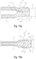
- Fig. 15a is a side view illustrating an electromagnetic shield structure 1d provided on the electromagnetic shield pipe 3
- Fig. 15b is a plan view.
- the electromagnetic shield structure 1d includes the electromagnetic shield pipe 3, the cables 9a and 9b, the braided wires 11a and 11b, crimp members 13a and 13b, and the like.
- the end portion of the braided wire 11a covers the outer circumference of the metal layer 7 of the end portion of the electromagnetic shield pipe 3 while being in a cylindrical shape.
- the braided wire 11a is fixed with the crimp member 13a on the outer circumference of the electromagnetic shield pipe 3.
- the end portion of the braided wire 1 1b is disposed on the outer circumference of the braided wire 11a and the crimp member 13a.
- the sheet-like portion 15b of the end portion of the braided wire 1 1b is disposed on the base portion side with respect to the braided wire 11a and crimped by the crimp member 13b on the exposed portion of the metal layer 7 of the end portion of the electromagnetic shield pipe 3. That is, the braided wire 11a and the braided wire 11b are fixed with the crimp members 13a and 13b on the outer circumference of the electromagnetic shield pipe 3 at different positions in the longitudinal direction of the electromagnetic shield pipe 3.
- the braided wire 11a is fixed with the crimp member 13a on the end portion side of the electromagnetic shield pipe 3
- the braided Wire 11b is fixed with the crimp member 13b through the outer circumference of the crimp member 13a on the base portion side of the electromagnetic shield pipe 3.
- Fig. 16a is a cross-sectional view taken along line C-C of Fig. 15b
- Fig. 16b is a cross-sectional view taken along line D-D of Fig. 15b
- the braided wire 11a is crimped and fixed with the crimp member 13a.
- the braided wire 11a is fixed across the entire circumference in the circumferential direction of the electromagnetic shield pipe 3.
- a gap is formed between the braided wire 11a and the outer layer 5. That is, the metal layer 7 is exposed on the tip end side of the braided wire 11a.
- a head portion 14 is provided on the crimp members 13a and 13b.
- the head portion 14 is a protruding portion that protrudes to the outside on the crimp members 13a and 13b.
- the protruding portion has a linear, bent, or folded shape, for example. Note that, as for the crimp members 13a and 13b illustrated in Fig. 16a and Fig. 16b , an example in which the base of the head portion 14, which is the protruding portion, is tightened and has a folded shape is given.
- the sheet-like portion 15b of the end portion of the braided wire 11b covers the outer circumference of the crimp member 13a, and the vicinity of the end portion of the sheet-like portion 15b is disposed on the outer circumference of the metal layer 7 exposed from the tip end of the braided wire 11a and fixed with the crimp member 13b.
- the braided wire 11b is fixed on a substantially semicircle on an upper side in the circumferential direction of the electromagnetic shield pipe 3.
- the braided wire 11a is disposed on the outer circumference of the electromagnetic shield pipe 3 while being in a cylindrical shape, but the arrangement of the braided wire 11a is not limited to this.
- a sheet-like portion having the same shape as that of the sheet-like portion 15b may be provided in the end portion of the braided wire 11a and disposed on a substantially semicircle in the circumferential direction of the electromagnetic shield pipe 3.
- the braided wires 11a and 11b are disposed at different positions in the longitudinal direction of the electromagnetic shield pipe 3 and fixed with the crimp members 13a and 13b on the metal layer 7 of the electromagnetic shield pipe 3, respectively. That is, the braided wires 11a and 11b are crimped and fixed with the respective crimp members 13a and 13b of the electromagnetic shield pipe 3 without being overlapped in the portion where the crimp members 13a and 13b are disposed.
- the braided wire 11b is arranged from the end portion side to the base portion side of the electromagnetic shield pipe 3 through the outside of the head portion 14 of the crimp member 13a, and thus there are concerns about the damage of the braided wire 11b due to the contact with the head portion 14, depending on the arrangement of the braided wire 11b.
- a protective member 21 may be disposed between the braided wire 11b disposed outside and the head portion 14.
- the protective member 21 may be provided between the crimp member 13a and the braided wire 11b.
- the protective member 21 can use the same material as that of the braided wires 11a and 11b.
- the arrangement in the circumferential direction of the braided wire 11b may be applied to a position different from that of the head portion 14 in order to avoid the contact between the braided wire 11b and the head portion 14. That is, in the case where the braided wire 11a is fixed with the crimp member 13a on the end portion side of the electromagnetic shield pipe 3, and the braided wire 11b is fixed with the crimp member 13b through the outer circumference of the crimp member 13a on the base portion side of the electromagnetic shield pipe 3, the braided wire 11b is disposed so as to avoid the head portion 14 of the crimp member 13a.
- Fig. 17a is a cross-sectional view of the crimp member 13a in this case
- Fig. 17b is a cross-sectional view of the crimp member 13b.
- the braided wire 11b fixed on the base portion side of the electromagnetic shield pipe 3 is disposed from the end portion side to the base portion side of the electromagnetic shield pipe 3 at a position in the circumferential direction in which the head portion 14 of the crimp member 13a is not overlapped, thereby avoiding the contact between the braided wire 11b and the head portion 14. This can prevent damage of the braided wire 11b due to the contact with the head portion 14.
- the number of cables inserted into the electromagnetic shield pipe 3 is not limited to two.
- the cables 9a and 9b may be not one, but may be a plurality. Even in this case, the cables 9a and 9b exposed from the electromagnetic shield pipe 3 are respectively covered with the braided wires 11a and 11b, and the braided wires 11a and 11b are crimped at different positions in the longitudinal direction of the electromagnetic shield pipe 3.
- the cables inserted into the electromagnetic shield pipe 3 is not limited to the two systems of the cables 9a and 9b.
- three or more cables are inserted into the electromagnetic shield pipe 3
- three or more braided wires and crimp members are respectively used, and the braided wires are respectively fixed on the electromagnetic shield pipe 3 at positions different from each other in the longitudinal direction of the electromagnetic shield pipe 3 in such a manner so that respective braided wires are not overlapped with each other in each crimp member.
- the metal layer 7 of the end portion of the electromagnetic shield pipe 3 is exposed.
- the cables 9a and 9b are inserted into the electromagnetic shield pipe 3.
- a braided wire may be disposed on the outer circumference of the cable 9a or the cable 9b in the interior of the electromagnetic shield pipe 3.
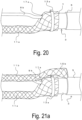
- Fig. 19a and Fig. 19b are views illustrating a state where the cable 9b exposed from the electromagnetic shield pipe 3 is covered with the braided wire 11a
- Fig. 19a is a side view
- Fig. 19b is a plan view.
- the end portion of the braided wire 11a covers the end portion (the metal layer 7) of the electromagnetic shield pipe 3 while being in a cylindrical shape.
- the covering interference of the braided wire 11a is adjusted so as to expose the metal layer 7 between the end portion of the braided wire 11a and the outer layer 5.
- the stitches of the braided wire 11a can be easily expanded, so that the diameter of the cylinder can be easily increased while the cylindrical shape is maintained.
- the end portion of the braided wire 11a can be expanded and to cover the outer circumference of the electromagnetic shield pipe 3.
- the hole 17a is formed in part of the braided wire 11a.
- the hole 17a is formed by expanding the metallic elemental wires of the braided wire 11a to both sides.
- the hole 17a is formed on the base portion side of the braided wire 11a with respect to a portion caused to cover the electromagnetic shield pipe 3.
- the hole 17a is a portion penetrated by the cable 9b.
- the hole 17a may be formed by opening the cylindrical shape of the braided wire 11a.
- the braided wire 11a is crimped and fixed by the crimp member 13a on the metal layer 7 of the end portion of the electromagnetic shield pipe 3.
- the braided wire 11a is fixed in a state of being disposed across the entire circumference of the metal layer 7.
- Fig. 21a and Fig. 21b are views illustrating a state where the cable 9b exposed from the electromagnetic shield pipe 3 (the braided wire 11a) is covered with the braided wire 11b, and Fig. 21a is a side view, and Fig. 21b is a plan view.
- the cylindrical portion of the end portion (the electromagnetic shield pipe 3 side) of the braided wire 11b is loosen, and the sheet-like portion 15b having a predetermined length is formed.
- the sheet-like portion 15b of the end portion of the braided wire 11b is arranged on the outside of the braided wire 11a and the crimp member 13a and disposed on the outer circumference of the metal layer 7 exposed between the braided wire 11a and the outer layer 5.
- the braided wire 11b is crimped and fixed with the crimp member 13b on the electromagnetic shield pipe 3.
- the braided wire 11a is disposed not to be overlapped with a portion on which the braided wire 11b is crimped with the crimp member 13b.
- the end portion (crimp portion) of the electromagnetic shield pipe 3 is covered with a rubber member or the like as appropriate.
- the electromagnetic shield structure 1d is formed.
- the same effect as that of the First Embodiment can be achieved.
- the braided wires 11a and 11b are crimped on the respective crimp portions without being overlapped with each other at different positions in the longitudinal direction of the electromagnetic 35 shield pipe 3. Consequently, in the portions where the crimp members 13a and 13b are disposed, there is no overlapping portion between the braided wires 11a and 11b, and the entire outer circumferential surface of each of the braided wires 11a and 11b is pressed by the crimp members 13a and 13b from the outer circumferential side, and the stable holding strength by the crimp members 13a and 13b can be secured.
- the braided wire 11a is disposed substantially on the entire circumference in the circumferential direction of the electromagnetic shield pipe 3, and the braided wire 11b is disposed substantially on a semicircle in the circumferential direction of the electromagnetic shield pipe 3, so that sufficient contact areas with respect to the metal layer 7 can be respectively secured.
- the protective member 21 is disposed between the braided wire 11b and the head portion 14 of the crimp member 13a, thereby preventing damage of the braided wire 11b due to the head portion 14.
- the braided wire 1 1b is disposed at a position different from that of the head portion 14 in the circumferential direction to avoid the head portion 14 of the crimp member 13a, thereby preventing damage of the braided wire 11b due to the head portion 14.
- Fig. 22a is a side view illustrating processes for forming an electromagnetic shield structure according to the Sixth Embodiment.
- the cable 9a exposed from the electromagnetic shield pipe 3 is inserted into the braided wire 11a.
- the end portion of the braided wire 11a is caused to cover the end portion (the metal layer 7) of the electromagnetic shield pipe 3 while being in a cylindrical shape.
- the metal layer 7 is exposed between the braided wire 11a and the outer layer 5.
- the hole 17a is formed in a part of the braided wire 11a. As described above, the hole 17a is a portion penetrated by the cable 9b. Thus, when the cable 9a is inserted into the braided wire 11a, the cable 9b is also inserted into the braided wire 11a, and the cable 9b is taken out from the hole 17a to the outside. In this state, the braided wire 11a is fixed with the crimp member 13a on the metal layer 7.
- Fig. 22b is a side view illustrating a state where the cable 9b is covered with the braided wire 11b.
- the sheet-like portion 15b is not formed at the end portion of the braided wire 11b being in a cylindrical shape.
- the hole 17b penetrated by the braided wire 11a (the cable 9a) is formed in the braided wire 11b.
- both the braided wire 11a (the cable 9a) and the cable 9b are inserted from the end portion of the braided wire 11b, and only the braided wire 11a (the cable 9a) is taken out from the hole 17b to the outside of the braided wire 11b, and the cable 9b is inserted into the braided wire 11b as it is.
- the end portion of the braided wire 11b is caused to cover the exposed portion of the metal layer 7 through the outside of the braided wire 11a and the crimp member 13a. That is, on the outer circumference of the metal layer 7 of the electromagnetic shield pipe 3, the braided wire 11a is disposed across the entire circumference, and the braided wire 11b is disposed across substantially the entire outer circumference of the metal layer 7 on the base portion side of the electromagnetic shield pipe 3 with respect to the braided wire 11a.
- Fig. 23 is a view illustrating an electromagnetic shield structure 1e in which the braided wire 11b is fixed with the crimp member 13b
- Fig. 24a is a cross-sectional view of a portion where the crimp member 13a is disposed
- Fig. 24b is a cross-sectional view of a portion where the crimp member 13b is disposed.
- the braided wires 11a and 11b are fixed with the crimp members 13a and 13b on the metal layer 7 of the electromagnetic shield pipe 3 at different positions in the longitudinal direction of the electromagnetic shield pipe 3.
- the end portions of the braided wires 11a and 11b respectively cover the outer circumference of the electromagnetic shield pipe 3 while being in a cylindrical shape.
- the cylindrical braided wires 11a and 11b are respectively disposed across the entire circumference of the electromagnetic shield pipe 3, so that the braided wires 11a and 1 1b are fixed across the entire outer circumference of the electromagnetic shield pipe 3 in the respective crimp portions.
- the same effect as that of the Fifth Embodiment can be achieved. That is, the braided wires 11a and 11b are respectively fixed at different positions in the longitudinal direction of the electromagnetic shield pipe 3, and thus the stability of holding strength or the stability of an energized state of the braided wires 11a and 11b can be obtained.
- the braided wire 11a penetrates the braided wire 11b through the hole 17b, and the braided wires 11a and 11b are fixed substantially on the entire circumference in the circumferential direction of the electromagnetic shield pipe 3 on the respective portions.
- both the braided wires 11a and 11b are respectively in contact with the metal layer 7 across the entire circumference, so that the contact areas between the braided wires 11a and 11b and the metal layer 7 can be secured.
- Fig. 25a is a side view illustrating an electromagnetic shield pipe 3
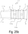
- Fig. 25b is a side view illustrating an electromagnetic shield structure 1f according to the Seventh Embodiment.
- Fig. 25b is a perspective view of the braided wires 11a and 1 1b, and the illustration of cables is omitted.
- the outer layer 5 in the vicinity of the end portion of the electromagnetic shield pipe 3 is not entirely removed, but the outer layer 5 partially remains in an annular form. That is, the exposed portions of the metal layers 7 are classified by the outer layers 5, and each of the exposed portions of the metal layers 7 is caught by the outer layers 5 and formed in an annular shape.
- the braided wires 11a and 11b are crimped by the crimp members 13a and 13b on the respective metal layers 7.
- the braided wires 11a and 11b steadily comes in contact with the metal layers 7, which leads to electrical conduction.
- the braided wire 11a is crimped with the crimp member 13a, thereby coming into contact with the metal layer 7.
- the braided wire 11b is crimped with the crimp member 13b, comes into contact with the metal layer 7, and is disposed outside the braided wire 11a and the crimp member 13a.
- the annular outer layer 5 on the tip end side is positioned on the tip end side with respect to the crimping position of the crimp member 13a and the second annular outer layer 5 is disposed between the crimping positions of the respective crimp members 13a and 13b.
- the annular outer layer 5 has a larger outer diameter than that of the exposed portion of the metal layer 7.
- a large diameter portion formed by the annular outer layer 5 is provided on the tip end side of the crimping position of each of the crimp members 13a and 13b with respect to the electromagnetic shield pipe 3.
- the same effect as that of the Fifth Embodiment can be achieved. That is, the braided wires 11a and 11b are respectively fixed at different positions in the longitudinal direction of the electromagnetic shield pipe 3, and thus the stability of holding strength or the stability of an energized state of the braided wires 11a and 11b can be obtained.
- the outer layers 5 provided in an annular form function as a stopper for preventing the crimp members 13a and 13b from coming off, so that the outer layers 5 can prevent the crimp members 13a and 13b from coming off from the electromagnetic shield pipe 3.
- another member such as resin may be adhered to the outer circumferential portion of the metal layer 7 in an annular form, thereby forming a large diameter portion on the tip end side of each of the crimping positions.
Landscapes
- Engineering & Computer Science (AREA)
- Microelectronics & Electronic Packaging (AREA)
- Architecture (AREA)
- Civil Engineering (AREA)
- Structural Engineering (AREA)
- Insulated Conductors (AREA)
- Shielding Devices Or Components To Electric Or Magnetic Fields (AREA)
- Details Of Indoor Wiring (AREA)
Description
- The present invention relates to an electromagnetic shield structure including a cable laid inside and used for an electric vehicle, for example.
- Conventionally, an electromagnetic shield pipe such as a metallic pipe or a composite pipe composed of a metallic layer and a resin layer is used as a protective pipe of a cable. Influence on the outside caused by noise that is generated from a cable inside or influence on the cable inside caused by noise on the outside can be suppressed by storing the cable in the electromagnetic shield pipe.
- Herein, for example, in an automobile, in some cases, a plurality of cables such as a high-voltage electric wire for connecting a high-voltage battery and an inverter and a low-voltage electric wire for connecting a low-voltage battery and a relay box is stored in one electromagnetic shield pipe. In this case, generally, noise from the high-voltage electric wire is shielded so as not to be transmitted to the low-voltage electric wire in the interior of the electromagnetic shield pipe. As this specific example, an example in which the low-voltage electric wire is inserted into a shielding member (e.g., braided wire) is given
- In contrast, the high-voltage electric wire and the low-voltage electric wire that are exposed from the end portion of the electromagnetic shield pipe are respectively inserted into the shielding member (e.g., braided wire) so as not to come under the influence of noise. This shielding member is connected to the electromagnetic shield pipe in a conductive manner and constitutes an electromagnetic shield structure.
- As this electromagnetic shield structure, for example, there is a method in which a braided wire into which the high-voltage electric wire is inserted and a braided wire into which the low-voltage electric wire is inserted are overlapped, and crimped with a crimp member such as a ring on a metallic portion (conductive portion) such as an end of an electromagnetic shield pipe (Patent Document 1).
-
Patent document 2 discloses an electromagnetic shield structure according to the preamble ofclaim 1. -
Patent document 3 discloses a cable shielding which has two halves such that there is no overlap over the shielding layers. -
- Patent Document 1:
JP 2015-106466 A - Patent Document 2:
JP 2006 310474 A - Patent Document 3:
US 2010/073006 A1 - However, in the electromagnetic shield structure of
Patent Document 1, on a connection portion between the braided wire and the electromagnetic shield pipe, there is an overlapping portion of the braided wire into which the high-voltage electric wire is inserted and the braided wire into which the low-voltage electric wire is inserted, and sections having a thickness different from the thickness of the overlapping portion occur on both sides of the overlapping portion. Thus, there are concerns about a holding strength of a crimping body might be reduced in a step of a thickness-varying portion of the braided wire which is the crimping body. - For example, holding strength on both sides of the overlapping portion of the braided wire is reduced due to heat cycle, repetitive bending, or tensile force, which might cause the shift or coming off of the braided wire, the coming off of the ring, and the like. Thus, there are concerns about stability regarding an energized state between the braided wire and the shield pipe or the holding strength of a crimp.
- The present invention has been made in view of these problems, and it is an object of the present invention to provide an electromagnetic shield structure capable of securing a stable energizing state between a flexible shield member and an electromagnetic shield pipe and maintaining the holding strength of the flexible shield member for the long term.
- In order to achieve the aforementioned object, the present invention provides an electromagnetic shield structure according to
claim 1 and a wire harness according toclaim 2. - According to the present invention, an electromagnetic shield structure that is capable of securing a stable energizing state between the flexible shield member and the electromagnetic shield pipe and maintaining the holding strength of the flexible shield member for the long term, can be provided.
-
-
Fig. 1a is a view illustrating anelectromagnetic shield pipe 3. -
Fig. 1b is a side view illustrating anelectromagnetic shield structure 1. -
Fig. 2a is a plan view illustrating a state where a cable 9b is covered with a braided wire 11b and a view viewed from an arrow B ofFig. 2b . -
Fig. 2b is a plan view illustrating a state where the cable 9b is covered with the braided wire 11b and a view viewed from an arrow A ofFig. 2a . -
Fig. 3a is a cross-sectional view of theelectromagnetic shield structure 1. -
Fig. 3b is another cross-sectional view of theelectromagnetic shield structure 1. -
Fig. 4 is another cross-sectional view of theelectromagnetic shield structure 1. -
Fig. 5a is another cross-sectional view of theelectromagnetic shield structure 1. -
Fig. 5b is another cross-sectional view of theelectromagnetic shield structure 1. -
Fig. 6a is a side view of an embodiment illustrating a state where acable 9a is covered with a braided wire 11a, said embodiment not belonging to the present invention. -
Fig. 6b is a plan view of an embodiment illustrating a state where thecable 9a is covered with the braided wire 11a said embodiment not belonging to the present invention. -
Fig. 7a is a side view illustrating a state where the cable 9b is covered with the braided wire 11b. -
Fig. 7b is a plan view illustrating a state where the cable 9b is covered with the braided wire 11b. -
Fig. 8 is a side view of an electromagnetic shield structure 1a. -
Fig. 9 is a cross-sectional view illustrating the electromagnetic shield structure 1a. -
Fig. 10a is a side view illustrating theelectromagnetic shield pipe 3 of an embodiment not belonging to the present invention. -
Fig. 10b is a side view illustrating an electromagnetic shield structure 1b. -
Fig. 11a is a side view of an embodiment illustrating a state where thecable 9a is covered with the braided wire 11a. -
Fig. 1 1b is a plan view of another embodiment illustrating a state where thecable 9a is covered with the braided wire 11a. -
Fig. 12a is a side view illustrating a state where the cable 9b is covered with the braided wire 11b. -
Fig. 12b is a plan view illustrating a state where the cable 9b is covered with the braided wire 11b. -
Fig. 13 is a side view illustrating an electromagnetic shield structure 1c. -
Fig. 14 is a cross-sectional view illustrating the electromagnetic shield structure 1c. -
Fig. 15a is a side view illustrating an electromagnetic shield structure 1d. -
Fig. 15b is a plan view illustrating the electromagnetic shield structure 1d. -
Fig. 16a is a cross-sectional view of a portion of a crimp member 13a of the electromagnetic shield structure 1d. -
Fig. 16b is a cross-sectional view of a portion of acrimp member 13b of the electromagnetic shield structure 1d. -
Fig. 17a is a cross-sectional view of the portion of a crimp member 13a of an embodiment of the electromagnetic shield structure 1d, said embodiment not belonging to the present invention. -
Fig. 17b is a cross-sectional view of the portion of acrimp member 13b of an embodiment of the electromagnetic shield structure 1d, said embodiment not belonging to the present invention. -
Fig. 18a is a cross-sectional view of the portion of the crimp member 13a of an embodiment of the electromagnetic shield structure 1d, said embodiment not belonging to the present invention. -
Fig. 18b is a cross-sectional view of the portion of thecrimp member 13b of an embodiment of the electromagnetic shield structure 1d, said embodiment not belonging to the present invention. -
Fig. 19a is a side view illustrating a state where thecable 9a is covered with the braided wire 11a. -
Fig. 19b is a plan view illustrating a state where thecable 9a is covered with the braided wire 11a. -
Fig. 20 is a side view illustrating a state where the braided wire 11a is fixed with the crimp member 13a. -
Fig. 21a is a side view illustrating a state where the cable 9b is covered with the braided wire 11b. -
Fig. 21b is a plan view illustrating a state where the cable 9b is covered with the braided wire 11b. -
Fig. 22a is a side view illustrating a state where thecable 9a is covered with the braided wire 11a. -
Fig. 22b is a side view illustrating a state where the cable 9b is covered with the braided wire 11b. -
Fig. 23 is a side view illustrating an electromagnetic shield structure 1e. -
Fig. 24a is a cross-sectional view of the portion of the crimp member 13a of the electromagnetic shield structure 1e. -
Fig. 24b is a cross-sectional view of the portion of thecrimp member 13b of the electromagnetic shield structure 1e. -
Fig. 25a is a plan view illustrating theelectromagnetic shield pipe 3. -
Fig. 25b is a plan view illustrating an electromagnetic shield structure 1f. - Hereinafter, an
electromagnetic shield pipe 3 according to an - embodiment not belonging to the present invention will be described.
Fig. 1a is a side view - illustrating the
electromagnetic shield pipe 3. Theelectromagnetic shield pipe 3 includes ametal layer 7 and anouter layer 5 made of resin and provided on the outer circumference thereof. Note that theelectromagnetic shield pipe 3 may be a metal pipe that does not include theouter layer 5 and may include another layer on the inside or outside of themetal layer 7. - Note that any material may be used for the
metal layer 7 as long as the
shield effect can be obtained, and for example, themetal layer 7 may be made of aluminum (including an aluminum alloy). - The
outer layer 5 of theelectromagnetic shield pipe 3 is peeled off by a predetermined length from an end portion. That is, themetal layer 7 is exposed only by a predetermined range on the end portion of theelectromagnetic shield pipe 3. The exposedmetal layer 7 serves as a connection portion connected to a cylindrical flexible shield member described later. - A
cable 9a being a first cable and a cable 9b being a second cable are inserted into theelectromagnetic shield pipe 3 and exposed from the end portion of theelectromagnetic shield pipe 3. That is, a plurality of cables is inserted into the interior of theelectromagnetic shield pipe 3. Note that thecable 9a is, for example, a high-voltage cable, and the cable 9b is, for example, a low-voltage cable. Note that in the interior of theelectromagnetic shield pipe 3, for example, the cable 9b is inserted into the cylindrical flexible shield member (not illustrated). As the cylindrical flexible shield member, a cylindrical braided wire in which a plated copper wire is braided is preferably used, and in the description below, an explanation is given by exemplifying a cylindrical braided wire as the cylindrical flexible shield member. Needless to say, the cylindrical flexible shield member is not limited to the cylindrical braided wire. -
Fig. 1b is a side view of theelectromagnetic shield structure 1 provided on theelectromagnetic shield pipe 3. Theelectromagnetic shield structure 1 includes theelectromagnetic shield pipe 3, thecables 9a and 9b, and braided wires 11a and 11b. The cylindrical braided wire 11a that is a first cylindrical flexible shield member covers thecable 9a exposed from the end portion of theelectromagnetic shield pipe 3. The cylindrical braided wire 11b that is a second cylindrical flexible shield member covers the cable 9b exposed from the end portion of theelectromagnetic shield pipe 3. Note that terminals (not illustrated) are connected to the end portions of the plurality ofcables 9a and 9b, and used as awire harness 20. -
Fig. 2a is a plan view of the end portion of the braided wire 11b that covers the cable 9b and a view viewed from the direction of an arrow B ofFig. 2b. Fig. 2b is a side view of the end portion of the braided wire 11b that covers the cable 9b and a view viewed from the direction of an arrow A ofFig. 2a . Note that the braided wire 11a for thecable 9a has similar form, and thus the illustration thereof will be omitted. - The cylindrical shape of the end portions (the end portions on the
electromagnetic shield pipe 3 side) of the braided wires 11a and 11b is loosened and expanded. That is, the end portions of the braided wires 11a and 11b are formed in a sheet-like shape. A sheet-like portion of the end portion of the braided wire 11a is a sheet-like portion 15a. In addition, a sheet-like portion of the end portion of the braided wire 11b is a sheet-like portion 15b. - The sheet-like portion 15a of the end portion of the braided wire 11a is crimped by a
crimp member 13 on an exposed portion of themetal layer 7 of the end portion of theelectromagnetic shield pipe 3. Similarly, the sheet-like portion 15b of the end portion of the braided wire 11b is crimped by thesame crimp member 13 on the exposed portion of themetal layer 7 of the end portion of theelectromagnetic shield pipe 3. That is, the braided wire 11a and the braided wire 11b are fixed with thecrimp member 13 on the outer circumference of theelectromagnetic shield pipe 3 at the same position in the longitudinal direction of theelectromagnetic shield pipe 3. -
Fig. 3a is a cross-sectional view of a portion perpendicular to the longitudinal direction of theelectromagnetic shield pipe 3 where thecrimp member 13 is disposed. The braided wire 11a (the sheet-like portion 15a) and the braided wire 11b (the sheet-like portion 15b) are fixed with thecrimp member 13 at different positions in the circumferential direction on the cross section perpendicular to the longitudinal direction of theelectromagnetic shield pipe 3. In the example illustrated, the braided wire 11a is fixed in a substantially semicircle on a lower side in the circumferential direction of theelectromagnetic shield pipe 3, and the braided wire 11b is fixed in another substantially semicircle (upper side in the diagram) in the circumferential direction of theelectromagnetic shield pipe 3. - Note that, as illustrated in
Fig. 3b , each of the sheet-like portion 15a of the braided wire 11a and the sheet-like portion 15b of the braided wire 11b is not required to be fixed in a substantially semicircle in the circumferential direction of theelectromagnetic shield pipe 3. For example, when the circumferential length of the braided wire 11a is greater than the circumferential length of the braided wire 11b, the width of the sheet-like portion 15a may be wider than the width of the sheet-like portion 15b. - As described above, the cylindrical end portions of the braided wires 11a and 11b are loosened, and each of the sheet-like portions 15a and 15b is formed on the end portion. The sheet-like portions 15a and 15b of the end portions of the braided wires 11a and 11b are disposed at different positions in the circumferential direction of the
electromagnetic shield pipe 3 and fixed on themetal layer 7 of theelectromagnetic shield pipe 3 with thecrimp member 13. Thus, in the cross section perpendicular to the longitudinal direction of theelectromagnetic shield pipe 3, the braided wires 11a and 11b in a portion crimped by thecrimp member 13 are fixed without being overlapped with each other in the circumferential direction of theelectromagnetic shield pipe 3. - That is, each of the plurality of braided wires 11a and 11b is fixed with the
crimp member 13 on the outer circumference of theelectromagnetic shield pipe 3. In this case, the entire outer circumferential surface of each of the plurality of braided wires 11a and 11b is pressed by thecrimp member 13 from the outer circumferential side, in the portion where thecrimp member 13 is disposed on the cross section perpendicular to the longitudinal direction of theelectromagnetic shield pipe 3. That is, the portion where thecrimp member 13 is disposed in the longitudinal direction of theelectromagnetic shield pipe 3 serves as a crimp portion where the braided wires 11a and 11b are pressed from the outer circumference. - Note that "each of the entire outer circumferential surfaces is pressed by the
crimp member 13 from the outer circumferential side" means that the entire outer circumferential surfaces of all the braided wires 11a and 11b are directly or indirectly pressed by thecrimp member 13 from the outer circumferential side. For example, when the braided wires 11a and 11b are overlapped with each other, and a step occurs in this part in the circumferential direction, a section to which pressing force generated by tightening by thecrimp member 13 from the outer circumferential side is not transmitted occurs in a part of any of the braided wires 11a and 11b on both sides of the step. In the present invention, the section to which this pressing force is not transmitted does not occur. That is, in the present invention, no gap occurs between the part of the outer circumferential surface of the braided wires 11a and 11b and thecrimp member 13 disposed on the outer circumferential side of the braided wires 11a and 11b (or another member disposed between thecrimp member 13 and each braided 10 wire). Thus, the entire outer circumferential surface of the braided wires 11a and 11b is adhered to members disposed on the outer circumferential side of the braided wires 11a and 11b. Note that this "gap" does not include a minuscule gap caused by depressions and recesses on the outer surface of the braided wires 11a and 11b between the braided wires and thecrimp member 13 or the like. Note that, considering that the pressing force from the outer circumferential side is appropriately transmitted to each of the braided wires 11a and 11b in the case when each of the braided wires 11a and 11b is crimped by thecrimp member 13, it is preferable that the thicknesses of the sheet-like portions 15a and 15b in the portion where thecrimp member 13 is disposed are substantially equal. - Note that the number of cables inserted into the
electromagnetic shield pipe 3 is not limited to two. For example, as illustrated inFig. 4 , thecables 9a and 9b may be not one, but may be a plurality. Even in this case, thecables 9a and 9b exposed from theelectromagnetic shield pipe 3 are respectively covered with the braided wires 11a and 11b and, the braided wires 11a and 11b are crimped at different positions in the circumferential direction. - In this case, the plurality of cables may be inserted into one braided wire, or different braided wire may be used for each cable. Even in this case, respective braided wires are disposed not to be overlapped with each other in a crimp portion. For example, the
cable 9a is a high-voltage system cable, and the cable 9b is a low-voltage system cable, and when cables are two systems, one system cable may be inserted into one braided wire. Note that, in many cases, both the number of high-voltage system cables and the number of low-voltage system cables are normally two or more. Thus, the high-voltage system cables and the low-voltage system cables are inserted into the braided wire for each system, thereby achieving shielding between the high-voltage system cables and the low-voltage system cables, between theelectromagnetic shield pipe 3 and a connector. - In addition, the cables inserted into the
electromagnetic shield pipe 3 are not limited to the two systems of thecables 9a and 9b. For example, when the cables inserted into theelectromagnetic shield pipe 3 are three or more systems, or when a three-phase alternating current wire is provided, three or more braided wires may be used, and the sheet-like portions of the end portions of respective braided wires are only required to be disposed in such a manner so as not to be overlapped with each other at different positions in the circumferential direction of theelectromagnetic shield pipe 3. - For example, as illustrated in
Fig. 5a , when threecables 9a, 9b and 9c are inserted into theelectromagnetic shield pipe 3, thecables 9a, 9b and 9c are covered with braided wires 11a, 11b, and 11c, respectively, and the braided wires 11a, 11b, and 11c are fixed at different positions in the circumferential direction. In this case, sheet-like portions 15a, 15b, and 15c are formed at respective end portions of the cylindrical braided wires 11a, 11b, and 11c, and the respective sheet-like portions 15a, 15b, and 15c are fixed on themetal layer 7 of theelectromagnetic shield pipe 3 at different positions in the circumferential direction of theelectromagnetic shield pipe 3. - In this case, as illustrated in
Fig. 5a , the circumferential length of the sheet-like portions 15a, 15b, and 15c (the braided wires 11a, 11b, and 11c) may be substantially equally divided and disposed in such a manner so as to be one third of the length of the circumferential direction. Alternatively, as illustrated inFig. 5b , the sheet-like portions 15a, 15b, and 15c (the braided wires 11a, 11b, and 11c) may be disposed in such a manner that the lengths of the circumferential direction are different from each other. In any case, on the cross section perpendicular to the longitudinal direction of theelectromagnetic shield pipe 3, the entire outer circumferential surface of each of the braided wires 11a, 11b, and 11c is pressed by thecrimp member 13 from the outer circumferential side. Note that in the description below, an explanation is given as to a case where twocables 9a and 9b are included, but in other embodiments, three or more cables may be included. In addition, considering that the pressing force from the outer circumferential side is appropriately transmitted to each of the braided wire 11a, 11b, and 11c in the case when each of the braided wire 11a, 11b, and 11c is tighten by thecrimp member 13, it is preferable that the thicknesses of the sheet-like portions 15a, 15b, and 15c in the portion where thecrimp member 13 is disposed are substantially equal. - Next, a manufacturing method of the
electromagnetic shield structure 1 will be described. First, themetal layer 7 of the end portion of theelectromagnetic shield pipe 3 is exposed. In addition, thecables 9a and 9b are inserted into theelectromagnetic shield pipe 3. Note that, in this case, a braided wire may be disposed on the outer circumference of thecable 9a or the cable 9b in the interior of theelectromagnetic shield pipe 3. - Subsequently, the
cable 9a exposed from theelectromagnetic shield pipe 3 is covered with the braided wire 11a. In this case, the cylindrical portion of the end portion of the braided wire 11a (on theelectromagnetic shield pipe 3 side) is loosened, and the sheet-like portion 15a having a predetermined length is formed. Similarly, the cable 9b exposed from theelectromagnetic shield pipe 3 is covered with the braided wire 11b. In this case, the cylindrical portion of the end portion of the braided wire 11b (on theelectromagnetic shield pipe 3 side) is loosened, and the sheet-like portion 15b having a predetermined length is formed. - Subsequently, the sheet-like portions 15a and 15b of the end portions of the braided wires 11a and 11b are disposed on the outer circumference of the
metal layer 7. In this case, the sheet-like portions 15a and 15b are disposed at different positions in the circumferential direction of theelectromagnetic shield pipe 3 so as not to be overlapped with each other. In this state, the braided wires 11a and 11b are crimped and fixed with thecrimp member 13 on theelectromagnetic shield pipe 3. Note that the end portion (crimp portion) of theelectromagnetic shield pipe 3 is covered with a rubber member or the like as appropriate. As described above, theelectromagnetic shield structure 1 is formed. - Hereinbefore, according to the First Embodiment, the braided wires 11a and 11b are crimped without being overlapped with each other at different positions in the circumferential direction of the
electromagnetic shield pipe 3 in the crimp portion. Thus, there is no change in thickness in the crimp portion due to the partial overlapping of the braided wires 11a and 11b. Consequently, in the portion where thecrimp member 13 is disposed, the entire outer circumferential surface of each of the braided wires 11a and 11b is pressed by thecrimp member 13 from the outer circumferential side, and the stable holding strength by thecrimp member 13 can be secured. - In addition, the braided wires 11a and 11b are respectively disposed in substantially semicircles in the circumferential direction of the
electromagnetic shield pipe 3, thereby respectively securing a sufficient contact area. - Next, a Second Embodiment not belonging to the present invention will be described.
Figs. 6a and 6b are views
illustrating processes for forming an electromagnetic shield structure according to the Second Embodiment, andFig. 6a is a side view, andFig. 6b is a plan view. Note that, in the description below, constituent elements which have the same effect will be assigned the same reference numerals as inFig. 1b and other drawings, and redundant descriptions of those constituent elements will be omitted. - In the present embodiment, first, the
cable 9a exposed from theelectromagnetic shield pipe 3 is inserted into the braided wire 11a. The end portion of the braided wire 11a covers the end portion (the metal layer 7) of theelectromagnetic shield pipe 3 while being formed in a cylindrical shape. Thus, in the present embodiment, which is different from the embodiment described above, it is not required to form the sheet-like portion 15a in the end portion of the braided wire 11a. - Note that the stitches of the braided wire 11a can be easily expanded, so that the diameter of the cylinder can be easily increased while the cylindrical shape is maintained. Thus, even when the braided wire 11a in accordance with the size of the
cable 9a is used, the end portion of the braided wire 11a can be expanded to cover the outer circumference of theelectromagnetic shield pipe 3. - The
holes 17a and 19 are formed in part of the braided wire 11a. Note that the hole 17a and thehole 19 are formed in the substantially same direction as the circumferential direction of the braided wire 11a. Theholes 17a and 19 are formed by expanding the metallic elemental wires of the braided wire 11a to 35 both sides. The hole 17a is formed on the base portion side of the braided wire 11a with respect to a portion that covers theelectromagnetic shield pipe 3. The hole 17a is a portion penetrated by the cable 9b. Thus, when thecable 9a is inserted from the end portion of the braided wire 11a, the cable 9b is also simultaneously inserted into the braided wire 11a, and the cable 9b is taken out from the hole 17a to the outside. - The
hole 19 is formed on the end portion side of the braided wire 11a with respect to the hole 17a. That is, thehole 19 is formed in a portion of the braided wire 11a, the portion that covers theelectromagnetic shield pipe 3. More specifically, as illustrated, the braided wire 11a covers the end portion of theelectromagnetic shield pipe 3 in such a manner so that thehole 19 is positioned at themetal layer 7. Note that the hole 17a and thehole 19 may communicate with each other. -
Fig. 7a andFig. 7b are views illustrating a state where the cable 9b is further covered with the braided wire 11b, andFig. 7a is a side view, andFig. 7b is a plan view. The sheet-like portion 15b is formed in the end portion of the braided wire 11b. That is, the cylindrical braided wire 11b is disposed on the cable 9b exposed from the braided wire 11a, and the sheet-like portion 15b is disposed so as to be overlapped with the braided wire 11a. - In this case, part of the sheet-like portion 15b is overlapped at a position of the
hole 19 of the braided wire 11a. Thus, a part of the sheet-like portion 15b is disposed so as to cover themetal layer 7 exposed from thehole 19. In this case, the width of the braided wire 11b is narrower that the width of thehole 19. This prevents the braided wire 11b from protruding from thehole 19 and from being overlapped with the braided wire 11a in the circumferential direction of thehole 19. - Further,
Fig. 8 is a view illustrating an electromagnetic shield structure 1a in which the braided wires 11a and 11b are fixed with thecrimp member 13, andFig. 9 is a cross-sectional view of a portion where thecrimp member 13 is disposed. As illustrated, the braided wires 11a and 11b are fixed with thecrimp member 13 on theelectromagnetic shield pipe 3 in the portion where thecrimp member 13 is disposed, corresponding to thehole 19. - As described above, the end portion of the braided wire 11a covers the outer circumference of the
electromagnetic shield pipe 3 while being in a cylindrical shape. In addition, thehole 19 is provided in part of the braided wire 11a positioned on the outer circumference of theelectromagnetic shield pipe 3, and the sheet-like portion 15b of the end portion of thebraided wire 1 1b covers the position of thehole 19. Further, the braided wires 11a and 11b are fixed with thecrimp member 13 on theelectromagnetic shield pipe 3 in a portion in the circumferential direction corresponding to thehole 19. This prevents the braided wires 11a and 11b from being partially overlapped with the outer circumference of theelectromagnetic shield pipe 3 in the crimp portion. - According to the Second Embodiment, the same effect as that of the First Embodiment can be achieved. That is, by removing the partial overlapping of the braided wires 11a and 11b in the crimp portion, the entire outer circumferential surface of each of the braided wires 11a and 11b is pressed by the
crimp member 13 from the outer circumferential side, and the stability of holding strength or the stability of an energized state can be obtained. - In addition, the
hole 19 is provided in the braided wire 11a, which makes it unnecessary to loosen the end portion of the braided wire 11a and form the sheet-like portion 15a. Note that, even in this case, thebraided wires 11a and 1 1b can be appropriately disposed by adjusting the size of thehole 19 in such a manner as to cover each of substantially semicircles of theelectromagnetic shield pipe 3. Note that considering that the pressing force from the outer circumferential side is appropriately transmitted to each of the braided wires 11a and 11b in the case where each of the braided wires 11a and 11b is tightened by thecrimp member 13, it is preferable that the thickness of the braided wire 11a and the thickness of the sheet-like portion 15b in the portion where thecrimp member 13 is disposed are substantially equal. - Next, a Third Embodiment not belonging to the present invention will be described.
Fig. 10a is a side view illustrating anelectromagnetic shield pipe 3, andFig. 10b is a side view illustrating an electromagnetic shield structure 1b according to the Third Embodiment. Note thatFig. 10b is a perspective view of thebraided wires 11a and 1 1b, and the illustration of cables is omitted. - In the present embodiment, the
outer layer 5 in the vicinity of the end portion of theelectromagnetic shield pipe 3 is not entirely removed, but theouter layer 5 remains in an annular shape in part of the tip end portion. That is, the exposed portion of themetal layer 7 is caught by theouter layers 5 and formed in an annular shape. - As illustrated in
Fig. 10b , the braided wires 11a and 11b are crimped by thecrimp member 13 on themetal layer 7 in such a manner that the braided wires 11a and 11b are not overlapped with each other. Thus, the braided wires 11a and 11b steadily comes in contact with themetal layer 7, which leads to electrical conduction. Note that the arrangement of the braided wires 11a and 11b can have any form as long as the partial overlapping is eliminated. - In this case, the annular
outer layer 5 on the tip end side is positioned on the tip end side with respect to a crimping position of thecrimp member 13. Theouter layer 5 has a larger outer diameter than that of the exposed portion of themetal layer 7. Thus, a large diameter portion formed by the annularouter layer 5 is provided on the tip end side of the crimping position of thecrimp member 13 with respect to theelectromagnetic shield pipe 3. Thus, even when the braided wires 11a and 11b are pulled, and thecrimp member 13 is shifted to the tip end side, the movement of thecrimp member 13 is regulated by theouter layer 5. Consequently, thecrimp member 13 can be prevented from coming off from theelectromagnetic shield pipe 3. - According to the Third Embodiment, the same effect as that of the First Embodiment can be achieved. That is, by removing the partial overlapping of the braided wires 11a and 11b in the portion where the
crimp member 13 is disposed, the entire outer circumferential surface of each of the braided wires 11a and 11b is pressed by thecrimp member 13 from the outer circumferential side, and the stability of holding strength or the stability of an energized state can be obtained. Note that, considering that the pressing force from the outer circumferential side is appropriately transmitted to each of the braided wires 11a and 11b in the case where each of the braided wires 11a and 11b is tighten by thecrimp member 13, it is preferable that the thicknesses of the sheet-like portions 15a and 15b in the portion where thecrimp member 13 is disposed are substantially equal. - In addition, the
outer layer 5 provided in an annular form functions as a stopper for preventing thecrimp member 13 from coming off, so that theouter layer 5 can prevent thecrimp member 13 from coming off from theelectromagnetic shield pipe 3. Note that, in place of theouter layer 5, another member such as resin may be adhered to the outer circumferential portion of themetal layer 7 in an annular form, thereby forming a large diameter portion on the tip end side of the crimping position. - Next, a Fourth Embodiment will be described.
Fig. 11a andFig. 11b are views illustrating processes for forming an electromagnetic shield structure according to the Fourth Embodiment, andFig. 11a is a side view, andFig. 11b is a plan view. - In the Fourth Embodiment, as is the case with the Second Embodiment, first, the
cable 9a exposed from theelectromagnetic shield pipe 3 is inserted into the braided wire 11a. Note that, as is the case with the Third Embodiment, theouter layer 5 may be provided on the tip end portion of theelectromagnetic shield pipe 3. The end portion of the braided wire 11a covers the end portion (the metal layer 7) of theelectromagnetic shield pipe 3 while being in a cylindrical shape. - The hole 17a is formed in part of the braided wire 11a. As described above, the hole 17a is a portion penetrated by the cable 9b. Thus, when the
cable 9a is inserted into the braided wire 11a, the cable 9b is also inserted into the braided wire 11a and taken out from the hole 17a to the outside. Note that 20 the hole 17a may be formed by opening the cylindrical shape of the braided wire 11a. - Further,
Fig. 12a and Fig. 12b are views illustrating a state where the cable 9b is covered with the braided wire 11b, andFig. 12a is a side view, andFig. 12b is a plan view. The sheet-like portion 15b is not formed at the end portion of the braided wire 11b which is in a cylindrical shape. A hole 17b penetrated by the braided wire 11a (thecable 9a) is formed in the braided wire 11b. Note that the hole 17b may be formed by opening the cylindrical shape of the braided wire 11b. - In this case, first, both the braided wire 11a (the
cable 9a) and the cable 9b are inserted from the end portion of the braided wire 11b, and only the braided wire 11a (thecable 9a) is taken out from the hole 17b to the outside of the braided wire 11b, and the cable 9b may be inserted into thebraided wire 1 1b as it is. - The end portion of the braided wire 11b covers the end portion of the
electromagnetic shield pipe 3 together with the braided wire 11a. That is, on the outer circumference of themetal layer 7 of theelectromagnetic shield pipe 3, the braided wire 11a is disposed across the entire circumference, and on the outer circumference of the braided wire 11a, the braided wire 11b is disposed across substantially the entire circumference. - Further,
Fig. 13 is a view illustrating an electromagnetic shield structure 1c in which the braided wires 11a and 11b are fixed with thecrimp member 13, andFig. 14 is a cross-sectional view of the crimp portion. As illustrated, on themetal layer 7, the braided wires 11a and 11b are fixed with thecrimp member 13 on theelectromagnetic shield pipe 3. - As described above, the end portions of the braided wires 11a and 11b cover the outer circumference of the
electromagnetic shield pipe 3 while being in a cylindrical shape. In this case, the cylindrical braided wires 11a and 11b are disposed across the entire circumference of theelectromagnetic shield pipe 3, so that thebraided wires 11a and 1 1b are overlapped with each other across the entire outer circumference of theelectromagnetic shield pipe 3 in the crimp portion. That is, the overlapping portion of the braided wires 11a and 11b is not partially formed in the circumferential direction of theelectromagnetic shield pipe 3, but the braided wires 11a and 11b are overlapped with each other across the entire circumference. Thus, there is no change in the thickness of the braided wires in the crimp portion. - According to the Fourth Embodiment, the same effect as that of the First Embodiment can be achieved. That is, a step due to the partial overlapping of the braided wires 11a and 11b is not formed in the crimp portion. Thus, in the portion where the
crimp member 13 is disposed, the entire outer circumferential surface of the braided wire 11b is pressed by thecrimp member 13 from the outer circumferential side, and the entire outer circumferential surface of the braided wire 11a is indirectly pressed by thecrimp member 13 via the braided wire 11a from the outer circumferential side, so that the stability of holding strength or the stability of an energized state can be obtained. Note that, considering that the pressing force from the outer circumferential side is appropriately transmitted to each of the braided wires 11a and 11b in the case 35 where each of the braided wires 11a and 11b is tighten by thecrimp member 13, it is preferable that the thicknesses of the braided wires 11a and 11b in the portion where thecrimp member 13 is disposed are not substantially changed in the respective circumferential directions. - Thus, in the present invention, both the braided wires 11a and 11b are overlapped with each other across the entire circumference, so that change in the thicknesses of the braided wires can be prevented in the crimp portion. Consequently, an influence caused by a step portion due to the partial overlapping of the braided wires is suppressed.
- Next, a Fifth Embodiment not belonging to the present invention will be described.
Fig. 15a is a side view illustrating an electromagnetic shield structure 1d provided on theelectromagnetic shield pipe 3, andFig. 15b is a plan view. The electromagnetic shield structure 1d includes theelectromagnetic shield pipe 3, thecables 9a and 9b, the braided wires 11a and 11b,crimp members 13a and 13b, and the like. - The end portion of the braided wire 11a covers the outer circumference of the
metal layer 7 of the end portion of theelectromagnetic shield pipe 3 while being in a cylindrical shape. The braided wire 11a is fixed with the crimp member 13a on the outer circumference of theelectromagnetic shield pipe 3. In contrast, the end portion of thebraided wire 1 1b is disposed on the outer circumference of the braided wire 11a and the crimp member 13a. - The sheet-like portion 15b of the end portion of the
braided wire 1 1b is disposed on the base portion side with respect to the braided wire 11a and crimped by thecrimp member 13b on the exposed portion of themetal layer 7 of the end portion of theelectromagnetic shield pipe 3. That is, the braided wire 11a and the braided wire 11b are fixed with thecrimp members 13a and 13b on the outer circumference of theelectromagnetic shield pipe 3 at different positions in the longitudinal direction of theelectromagnetic shield pipe 3. In the example illustrated, the braided wire 11a is fixed with the crimp member 13a on the end portion side of theelectromagnetic shield pipe 3, and the braided Wire 11b is fixed with thecrimp member 13b through the outer circumference of the crimp member 13a on the base portion side of theelectromagnetic shield pipe 3. -
Fig. 16a is a cross-sectional view taken along line C-C ofFig. 15b , andFig. 16b is a cross-sectional view taken along line D-D ofFig. 15b . On the cross section perpendicular to the longitudinal direction of theelectromagnetic shield pipe 3, the braided wire 11a is crimped and fixed with the crimp member 13a. In the example illustrated, the braided wire 11a is fixed across the entire circumference in the circumferential direction of theelectromagnetic shield pipe 3. In this case, a gap is formed between the braided wire 11a and theouter layer 5. That is, themetal layer 7 is exposed on the tip end side of the braided wire 11a. In addition, ahead portion 14 is provided on thecrimp members 13a and 13b. Thehead portion 14 is a protruding portion that protrudes to the outside on thecrimp members 13a and 13b. The protruding portion has a linear, bent, or folded shape, for example. Note that, as for thecrimp members 13a and 13b illustrated inFig. 16a and Fig. 16b , an example in which the base of thehead portion 14, which is the protruding portion, is tightened and has a folded shape is given. - The sheet-like portion 15b of the end portion of the braided wire 11b covers the outer circumference of the crimp member 13a, and the vicinity of the end portion of the sheet-like portion 15b is disposed on the outer circumference of the
metal layer 7 exposed from the tip end of the braided wire 11a and fixed with thecrimp member 13b. In the example illustrated, the braided wire 11b is fixed on a substantially semicircle on an upper side in the circumferential direction of theelectromagnetic shield pipe 3. Note that inFig. 15a, Fig. 15b , andFig. 16a , the braided wire 11a is disposed on the outer circumference of theelectromagnetic shield pipe 3 while being in a cylindrical shape, but the arrangement of the braided wire 11a is not limited to this. For example, a sheet-like portion having the same shape as that of the sheet-like portion 15b may be provided in the end portion of the braided wire 11a and disposed on a substantially semicircle in the circumferential direction of theelectromagnetic shield pipe 3. - Thus, the braided wires 11a and 11b are disposed at different positions in the longitudinal direction of the
electromagnetic shield pipe 3 and fixed with thecrimp members 13a and 13b on themetal layer 7 of theelectromagnetic shield pipe 3, respectively. That is, the braided wires 11a and 11b are crimped and fixed with therespective crimp members 13a and 13b of theelectromagnetic shield pipe 3 without being overlapped in the portion where thecrimp members 13a and 13b are disposed. - Note that, as described above, the braided wire 11b is arranged from the end portion side to the base portion side of the
electromagnetic shield pipe 3 through the outside of thehead portion 14 of the crimp member 13a, and thus there are concerns about the damage of the braided wire 11b due to the contact with thehead portion 14, depending on the arrangement of the braided wire 11b. Thus, aprotective member 21 may be disposed between the braided wire 11b disposed outside and thehead portion 14. That is, in the case where the braided wire 11a is fixed with the crimp member 13a on the end portion side of theelectromagnetic shield pipe 3, and the braided wire 11b is fixed with thecrimp member 13b through the outer circumference of the crimp member 13a on the base portion side of theelectromagnetic shield pipe 3, theprotective member 21 may be provided between the crimp member 13a and the braided wire 11b. For example, theprotective member 21 can use the same material as that of the braided wires 11a and 11b. - Note that the arrangement in the circumferential direction of the braided wire 11b (the sheet-like portion 15b) may be applied to a position different from that of the
head portion 14 in order to avoid the contact between the braided wire 11b and thehead portion 14. That is, in the case where the braided wire 11a is fixed with the crimp member 13a on the end portion side of theelectromagnetic shield pipe 3, and the braided wire 11b is fixed with thecrimp member 13b through the outer circumference of the crimp member 13a on the base portion side of theelectromagnetic shield pipe 3, the braided wire 11b is disposed so as to avoid thehead portion 14 of the crimp member 13a. -
Fig. 17a is a cross-sectional view of the crimp member 13a in this case, andFig. 17b is a cross-sectional view of thecrimp member 13b. The braided wire 11b fixed on the base portion side of theelectromagnetic shield pipe 3 is disposed from the end portion side to the base portion side of theelectromagnetic shield pipe 3 at a position in the circumferential direction in which thehead portion 14 of the crimp member 13a is not overlapped, thereby avoiding the contact between the braided wire 11b and thehead portion 14. This can prevent damage of the braided wire 11b due to the contact with thehead portion 14. - Note that, as described above, the number of cables inserted into the
electromagnetic shield pipe 3 is not limited to two. For example, as illustrated inFig. 18a and Fig. 18b that are cross-sectional views of a portion where thecrimp member 13a and 13b are disposed, thecables 9a and 9b may be not one, but may be a plurality. Even in this case, thecables 9a and 9b exposed from theelectromagnetic shield pipe 3 are respectively covered with the braided wires 11a and 11b, and the braided wires 11a and 11b are crimped at different positions in the longitudinal direction of theelectromagnetic shield pipe 3. - In addition, the cables inserted into the
electromagnetic shield pipe 3 is not limited to the two systems of thecables 9a and 9b. For example, when three or more cables are inserted into theelectromagnetic shield pipe 3, three or more braided wires and crimp members are respectively used, and the braided wires are respectively fixed on theelectromagnetic shield pipe 3 at positions different from each other in the longitudinal direction of theelectromagnetic shield pipe 3 in such a manner so that respective braided wires are not overlapped with each other in each crimp member. - Next, a manufacturing method of the electromagnetic shield structure 1d will be described. First, the
metal layer 7 of the end portion of theelectromagnetic shield pipe 3 is exposed. In addition, thecables 9a and 9b are inserted into theelectromagnetic shield pipe 3. Note that, in this case, a braided wire may be disposed on the outer circumference of thecable 9a or the cable 9b in the interior of theelectromagnetic shield pipe 3. - Further,
Fig. 19a and Fig. 19b are views illustrating a state where the cable 9b exposed from theelectromagnetic shield pipe 3 is covered with the braided wire 11a, andFig. 19a is a side view, andFig. 19b is a plan view. The end portion of the braided wire 11a covers the end portion (the metal layer 7) of theelectromagnetic shield pipe 3 while being in a cylindrical shape. In this case, the covering interference of the braided wire 11a is adjusted so as to expose themetal layer 7 between the end portion of the braided wire 11a and theouter layer 5. - Note that the stitches of the braided wire 11a can be easily expanded, so that the diameter of the cylinder can be easily increased while the cylindrical shape is maintained. Thus, even when the braided wire 11a in accordance with the size of the
cable 9a is used, the end portion of the braided wire 11a can be expanded and to cover the outer circumference of theelectromagnetic shield pipe 3. - The hole 17a is formed in part of the braided wire 11a. The hole 17a is formed by expanding the metallic elemental wires of the braided wire 11a to both sides. The hole 17a is formed on the base portion side of the braided wire 11a with respect to a portion caused to cover the
electromagnetic shield pipe 3. The hole 17a is a portion penetrated by the cable 9b. Thus, when thecable 9a is inserted from the end portion of the braided wire 11a, the cable 9b is also simultaneously inserted into the braided wire 11a, and the cable 9b is taken out from the hole 17a to the outside. Note that the hole 17a may be formed by opening the cylindrical shape of the braided wire 11a. - Next, as illustrated in
Fig. 20 , the braided wire 11a is crimped and fixed by the crimp member 13a on themetal layer 7 of the end portion of theelectromagnetic shield pipe 3. Thus, the braided wire 11a is fixed in a state of being disposed across the entire circumference of themetal layer 7. - Further,
Fig. 21a andFig. 21b are views illustrating a state where the cable 9b exposed from the electromagnetic shield pipe 3 (the braided wire 11a) is covered with the braided wire 11b, andFig. 21a is a side view, andFig. 21b is a plan view. The cylindrical portion of the end portion (theelectromagnetic shield pipe 3 side) of the braided wire 11b is loosen, and the sheet-like portion 15b having a predetermined length is formed. - The sheet-like portion 15b of the end portion of the braided wire 11b is arranged on the outside of the braided wire 11a and the crimp member 13a and disposed on the outer circumference of the
metal layer 7 exposed between the braided wire 11a and theouter layer 5. In this state, the braided wire 11b is crimped and fixed with thecrimp member 13b on theelectromagnetic shield pipe 3. In this case, the braided wire 11a is disposed not to be overlapped with a portion on which the braided wire 11b is crimped with thecrimp member 13b. In this state, the end portion (crimp portion) of theelectromagnetic shield pipe 3 is covered with a rubber member or the like as appropriate. As described above, the electromagnetic shield structure 1d is formed. - According to the Fifth Embodiment, the same effect as that of the First Embodiment can be achieved. In addition, the braided wires 11a and 11b are crimped on the respective crimp portions without being overlapped with each other at different positions in the longitudinal direction of the electromagnetic 35
shield pipe 3. Consequently, in the portions where thecrimp members 13a and 13b are disposed, there is no overlapping portion between the braided wires 11a and 11b, and the entire outer circumferential surface of each of the braided wires 11a and 11b is pressed by thecrimp members 13a and 13b from the outer circumferential side, and the stable holding strength by thecrimp members 13a and 13b can be secured. - In addition, the braided wire 11a is disposed substantially on the entire circumference in the circumferential direction of the
electromagnetic shield pipe 3, and the braided wire 11b is disposed substantially on a semicircle in the circumferential direction of theelectromagnetic shield pipe 3, so that sufficient contact areas with respect to themetal layer 7 can be respectively secured. - In addition, the
protective member 21 is disposed between the braided wire 11b and thehead portion 14 of the crimp member 13a, thereby preventing damage of the braided wire 11b due to thehead portion 14. - In addition, the
braided wire 1 1b is disposed at a position different from that of thehead portion 14 in the circumferential direction to avoid thehead portion 14 of the crimp member 13a, thereby preventing damage of the braided wire 11b due to thehead portion 14. - Next, a Sixth Embodiment not belonging to the present invention will be described.
Fig. 22a is a side view illustrating processes for forming an electromagnetic shield structure according to the Sixth Embodiment. - In the Sixth Embodiment, as is the case with the Fifth Embodiment, first, as illustrated in
Fig. 22a , thecable 9a exposed from theelectromagnetic shield pipe 3 is inserted into the braided wire 11a. The end portion of the braided wire 11a is caused to cover the end portion (the metal layer 7) of theelectromagnetic shield pipe 3 while being in a cylindrical shape. In this case, themetal layer 7 is exposed between the braided wire 11a and theouter layer 5. - The hole 17a is formed in a part of the braided wire 11a. As described above, the hole 17a is a portion penetrated by the cable 9b. Thus, when the
cable 9a is inserted into the braided wire 11a, the cable 9b is also inserted into the braided wire 11a, and the cable 9b is taken out from the hole 17a to the outside. In this state, the braided wire 11a is fixed with the crimp member 13a on themetal layer 7. - Further,
Fig. 22b is a side view illustrating a state where the cable 9b is covered with the braided wire 11b. The sheet-like portion 15b is not formed at the end portion of the braided wire 11b being in a cylindrical shape. The hole 17b penetrated by the braided wire 11a (thecable 9a) is formed in the braided wire 11b. - In this case, first, both the braided wire 11a (the
cable 9a) and the cable 9b are inserted from the end portion of the braided wire 11b, and only the braided wire 11a (thecable 9a) is taken out from the hole 17b to the outside of the braided wire 11b, and the cable 9b is inserted into the braided wire 11b as it is. - The end portion of the braided wire 11b is caused to cover the exposed portion of the
metal layer 7 through the outside of the braided wire 11a and the crimp member 13a. That is, on the outer circumference of themetal layer 7 of theelectromagnetic shield pipe 3, the braided wire 11a is disposed across the entire circumference, and the braided wire 11b is disposed across substantially the entire outer circumference of themetal layer 7 on the base portion side of theelectromagnetic shield pipe 3 with respect to the braided wire 11a. - Further,
Fig. 23 is a view illustrating an electromagnetic shield structure 1e in which the braided wire 11b is fixed with thecrimp member 13b, andFig. 24a is a cross-sectional view of a portion where the crimp member 13a is disposed, andFig. 24b is a cross-sectional view of a portion where thecrimp member 13b is disposed. As illustrated, the braided wires 11a and 11b are fixed with thecrimp members 13a and 13b on themetal layer 7 of theelectromagnetic shield pipe 3 at different positions in the longitudinal direction of theelectromagnetic shield pipe 3. - As illustrated in
Fig. 24a andFig. 24b , the end portions of the braided wires 11a and 11b respectively cover the outer circumference of theelectromagnetic shield pipe 3 while being in a cylindrical shape. In this case, the cylindrical braided wires 11a and 11b are respectively disposed across the entire circumference of theelectromagnetic shield pipe 3, so that thebraided wires 11a and 1 1b are fixed across the entire outer circumference of theelectromagnetic shield pipe 3 in the respective crimp portions. - According to the Sixth Embodiment, the same effect as that of the Fifth Embodiment can be achieved. That is, the braided wires 11a and 11b are respectively fixed at different positions in the longitudinal direction of the
electromagnetic shield pipe 3, and thus the stability of holding strength or the stability of an energized state of the braided wires 11a and 11b can be obtained. - In addition, the braided wire 11a penetrates the braided wire 11b through the hole 17b, and the braided wires 11a and 11b are fixed substantially on the entire circumference in the circumferential direction of the
electromagnetic shield pipe 3 on the respective portions. Thus, both the braided wires 11a and 11b are respectively in contact with themetal layer 7 across the entire circumference, so that the contact areas between the braided wires 11a and 11b and themetal layer 7 can be secured. - Next, a Seventh Embodiment not belonging to the present invention will be described.
Fig. 25a is a side view illustrating anelectromagnetic shield pipe 3, andFig. 25b is a side view illustrating an electromagnetic shield structure 1f according to the Seventh Embodiment. Note thatFig. 25b is a perspective view of thebraided wires 11a and 1 1b, and the illustration of cables is omitted. - In the present embodiment, the
outer layer 5 in the vicinity of the end portion of theelectromagnetic shield pipe 3 is not entirely removed, but theouter layer 5 partially remains in an annular form. That is, the exposed portions of themetal layers 7 are classified by theouter layers 5, and each of the exposed portions of themetal layers 7 is caught by theouter layers 5 and formed in an annular shape. - As illustrated in
Fig. 25b , the braided wires 11a and 11b are crimped by thecrimp members 13a and 13b on the respective metal layers 7. Thus, the braided wires 11a and 11b steadily comes in contact with themetal layers 7, which leads to electrical conduction. Note that the braided wire 11a is crimped with the crimp member 13a, thereby coming into contact with themetal layer 7. - The braided wire 11b is crimped with the
crimp member 13b, comes into contact with themetal layer 7, and is disposed outside the braided wire 11a and the crimp member 13a. - In this case, the annular
outer layer 5 on the tip end side is positioned on the tip end side with respect to the crimping position of the crimp member 13a and the second annularouter layer 5 is disposed between the crimping positions of therespective crimp members 13a and 13b. The annularouter layer 5 has a larger outer diameter than that of the exposed portion of themetal layer 7. Thus, a large diameter portion formed by the annularouter layer 5 is provided on the tip end side of the crimping position of each of thecrimp members 13a and 13b with respect to theelectromagnetic shield pipe 3. Thus, even when the braided wires 11a and 11b are pulled, and thecrimp members 13a and 13b are shifted to the tip end side, the movement of thecrimp members 13a and 13b is regulated by theouter layer 5. Consequently, thecrimp members 13a and 13b can be prevented from coming off from theelectromagnetic shield pipe 3. - According to the Seventh Embodiment, the same effect as that of the Fifth Embodiment can be achieved. That is, the braided wires 11a and 11b are respectively fixed at different positions in the longitudinal direction of the
electromagnetic shield pipe 3, and thus the stability of holding strength or the stability of an energized state of the braided wires 11a and 11b can be obtained. - In addition, the
outer layers 5 provided in an annular form function as a stopper for preventing thecrimp members 13a and 13b from coming off, so that theouter layers 5 can prevent thecrimp members 13a and 13b from coming off from theelectromagnetic shield pipe 3. Note that, in place of theouter layers 5, another member such as resin may be adhered to the outer circumferential portion of themetal layer 7 in an annular form, thereby forming a large diameter portion on the tip end side of each of the crimping positions. - Although embodiments of the present invention have been described above with reference to the accompanying drawings, the technical scope of the present invention is not affected by the above-described embodiments. It will be apparent to those skilled in the art that various variations and modifications can be made to the present invention within the scope of the technical ideas described in the appended claims. Thus, it is intended that these variations and modifications are within the technical scope of the present invention.
-
- 1, 1a, 1b, 1c, 1d, 1e, 1f Electromagnetic shield structure
- 3 Electromagnetic shield pipe
- 5 Outer layer
- 7 Metal layer
- 9a, 9b, 9c Cable
- 11a, 11b, 11c Braided wire
- 13a, 13b Crimp member
- 14 Head portion
- 15a, 15b, 15c Sheet-like portion
- 17a, 17b, 19 Hole
- 20 Wire harness
- 21 Protective member
Claims (2)
- An electromagnetic shield structure (1c) comprising:an electromagnetic shield pipe;a plurality of cables (9a, 9b) configured to be inserted into the electromagnetic shield pipe (11a, 11b) and exposed from an end portion of the electromagnetic shield pipe (11a, 11b); anda plurality of cylindrical flexible shield members (11a, 11b) configured to cover the plurality of cables (9a, 9b) exposed from the end portion of the electromagnetic shield pipe, whereinthe plurality of cylindrical flexible shield members (11a, 11b) is fixed with a crimp member (13) on an outer circumference of the electromagnetic shield pipe, andan entire outer circumferential surface of each of the plurality of cylindrical flexible shield members (11a, 11b) is pressed by the crimp member (13) from an outer circumferential side, on a cross section perpendicular to a longitudinal direction of the electromagnetic shield pipe (11a, 11b) in a portion where the crimp member (13) is disposed,whereinthe plurality of cylindrical flexible shield members (11a, 11b) is fixed with the crimp member (13) at an identical position in the longitudinal direction of the electromagnetic shield pipe (11a, 11b), characterized in thatthe plurality of cylindrical flexible shield members (11a, 11b) is fixed with the crimp member (13) in a state of being overlapped across an entire circumference in a circumferential direction, on a cross section perpendicular to the longitudinal direction of the electromagnetic shield pipe (11a, 11b).
- A wire harness comprising:the electromagnetic shield structure (1c) according to claim 1; andthe plurality of cables (9a, 9b) disposed in an interior of the electromagnetic shield pipe (11a, 11b).
Applications Claiming Priority (4)
| Application Number | Priority Date | Filing Date | Title |
|---|---|---|---|
| JP2016187057 | 2016-09-26 | ||
| JP2016187052 | 2016-09-26 | ||
| EP17853227.1A EP3518642B1 (en) | 2016-09-26 | 2017-09-26 | Electromagnetic shield structure and wire harness |
| PCT/JP2017/034686 WO2018056460A1 (en) | 2016-09-26 | 2017-09-26 | Electromagnetic shield structure and wire harness |
Related Parent Applications (2)
| Application Number | Title | Priority Date | Filing Date |
|---|---|---|---|
| EP17853227.1A Division-Into EP3518642B1 (en) | 2016-09-26 | 2017-09-26 | Electromagnetic shield structure and wire harness |
| EP17853227.1A Division EP3518642B1 (en) | 2016-09-26 | 2017-09-26 | Electromagnetic shield structure and wire harness |
Publications (2)
| Publication Number | Publication Date |
|---|---|
| EP4064812A1 EP4064812A1 (en) | 2022-09-28 |
| EP4064812B1 true EP4064812B1 (en) | 2024-09-11 |
Family
ID=61690465
Family Applications (2)
| Application Number | Title | Priority Date | Filing Date |
|---|---|---|---|
| EP17853227.1A Active EP3518642B1 (en) | 2016-09-26 | 2017-09-26 | Electromagnetic shield structure and wire harness |
| EP22174572.2A Active EP4064812B1 (en) | 2016-09-26 | 2017-09-26 | Electromagnetic shield structure and wire harness |
Family Applications Before (1)
| Application Number | Title | Priority Date | Filing Date |
|---|---|---|---|
| EP17853227.1A Active EP3518642B1 (en) | 2016-09-26 | 2017-09-26 | Electromagnetic shield structure and wire harness |
Country Status (5)
| Country | Link |
|---|---|
| US (3) | US10660248B2 (en) |
| EP (2) | EP3518642B1 (en) |
| JP (1) | JP6979957B2 (en) |
| CN (1) | CN109792856B (en) |
| WO (1) | WO2018056460A1 (en) |
Families Citing this family (11)
| Publication number | Priority date | Publication date | Assignee | Title |
|---|---|---|---|---|
| JP2018120788A (en) * | 2017-01-26 | 2018-08-02 | 住友電装株式会社 | Wire harness and connection structure of wire harness |
| JP6855966B2 (en) * | 2017-07-19 | 2021-04-07 | 住友電装株式会社 | Wire harness |
| JP6927126B2 (en) | 2018-03-30 | 2021-08-25 | 住友電装株式会社 | Wire harness |
| JP6819641B2 (en) * | 2018-03-30 | 2021-01-27 | 住友電装株式会社 | Wire harness |
| JP6927125B2 (en) * | 2018-03-30 | 2021-08-25 | 住友電装株式会社 | Wire harness |
| JP6819642B2 (en) * | 2018-03-30 | 2021-01-27 | 住友電装株式会社 | Wire harness |
| JP6691164B2 (en) | 2018-04-04 | 2020-04-28 | 矢崎総業株式会社 | Branching circuit body and wire branching method |
| US11825640B2 (en) * | 2019-07-02 | 2023-11-21 | Delfingen Industry | Electromagnetic shielding device |
| JP7524674B2 (en) * | 2020-08-26 | 2024-07-30 | 住友電装株式会社 | Wire Harness Unit |
| EP4432497A1 (en) * | 2023-03-14 | 2024-09-18 | Abb Schweiz Ag | Adaptor for connecting and securing different harness protection systems |
| WO2025134740A1 (en) * | 2023-12-19 | 2025-06-26 | 矢崎総業株式会社 | Wire harness |
Family Cites Families (19)
| Publication number | Priority date | Publication date | Assignee | Title |
|---|---|---|---|---|
| JP2002218621A (en) * | 2001-01-17 | 2002-08-02 | Yazaki Corp | Termination structure of shielded wires |
| JP4511988B2 (en) * | 2005-04-27 | 2010-07-28 | 株式会社オートネットワーク技術研究所 | Shield conductive path |
| JP5186186B2 (en) | 2007-11-15 | 2013-04-17 | 矢崎総業株式会社 | Shield shell mounting structure |
| US20100073006A1 (en) * | 2008-09-23 | 2010-03-25 | International Business Machines Corporation | Apparatus and Method of Charge Induction for Cable to System Testing |
| JP5362270B2 (en) * | 2008-07-03 | 2013-12-11 | 矢崎総業株式会社 | Shielded wire, braided terminal processing method of shielded wire, and braided terminal processing apparatus |
| JP5566716B2 (en) * | 2010-02-05 | 2014-08-06 | 矢崎総業株式会社 | Wire harness |
| JP2013073987A (en) * | 2011-09-27 | 2013-04-22 | Yazaki Corp | Shield structure and wire harness |
| JP5947513B2 (en) * | 2011-09-27 | 2016-07-06 | 矢崎総業株式会社 | Braiding and wire harness |
| JP6075968B2 (en) * | 2012-05-14 | 2017-02-08 | 矢崎総業株式会社 | Tubular braided caulking connection structure |
| EP2866540A1 (en) * | 2012-06-21 | 2015-04-29 | Furukawa Electric Co., Ltd. | Electromagnetic shield pipe, structure of shield cable, method for bending electromagnetic shield pipe, method for producing electromagnetic shield pipe, and method for processing end of shield cable |
| JP5915515B2 (en) * | 2012-12-25 | 2016-05-11 | 日立金属株式会社 | Connection structure between wire harness and shield shell and braided shield |
| JP6008249B2 (en) * | 2013-07-04 | 2016-10-19 | 住友電装株式会社 | Grommet |
| JP5971563B2 (en) * | 2013-11-29 | 2016-08-17 | 住友電装株式会社 | Wire shield structure |
| JP6149763B2 (en) * | 2014-03-03 | 2017-06-21 | 住友電装株式会社 | Shield conductive path |
| JP6135584B2 (en) * | 2014-04-02 | 2017-05-31 | 日立金属株式会社 | Wiring member |
| JP6256308B2 (en) * | 2014-11-06 | 2018-01-10 | 住友電装株式会社 | Wire harness shield structure |
| JP2016171734A (en) * | 2015-03-16 | 2016-09-23 | 住友電装株式会社 | Holder for pipe and wire harness |
| JP6582649B2 (en) * | 2015-07-10 | 2019-10-02 | 株式会社オートネットワーク技術研究所 | Shield structure |
| JP6691164B2 (en) * | 2018-04-04 | 2020-04-28 | 矢崎総業株式会社 | Branching circuit body and wire branching method |
-
2017
- 2017-09-26 WO PCT/JP2017/034686 patent/WO2018056460A1/en not_active Ceased
- 2017-09-26 JP JP2018540348A patent/JP6979957B2/en active Active
- 2017-09-26 CN CN201780058877.8A patent/CN109792856B/en active Active
- 2017-09-26 EP EP17853227.1A patent/EP3518642B1/en active Active
- 2017-09-26 EP EP22174572.2A patent/EP4064812B1/en active Active
-
2019
- 2019-03-25 US US16/363,466 patent/US10660248B2/en active Active
-
2020
- 2020-04-01 US US16/837,460 patent/US11006556B2/en active Active
-
2021
- 2021-04-13 US US17/228,828 patent/US11324150B2/en active Active
Also Published As
| Publication number | Publication date |
|---|---|
| EP3518642B1 (en) | 2022-07-27 |
| US11006556B2 (en) | 2021-05-11 |
| US20190223333A1 (en) | 2019-07-18 |
| US11324150B2 (en) | 2022-05-03 |
| JPWO2018056460A1 (en) | 2019-07-11 |
| US20200229329A1 (en) | 2020-07-16 |
| US10660248B2 (en) | 2020-05-19 |
| JP6979957B2 (en) | 2021-12-15 |
| EP3518642A1 (en) | 2019-07-31 |
| EP4064812A1 (en) | 2022-09-28 |
| CN109792856A (en) | 2019-05-21 |
| CN109792856B (en) | 2020-10-23 |
| WO2018056460A1 (en) | 2018-03-29 |
| EP3518642A4 (en) | 2020-05-27 |
| US20210235604A1 (en) | 2021-07-29 |
Similar Documents
| Publication | Publication Date | Title |
|---|---|---|
| EP4064812B1 (en) | Electromagnetic shield structure and wire harness | |
| EP3057105B1 (en) | Wire harness | |
| US9325120B2 (en) | Wire harness and connection structure of shield shell and braided shield | |
| US9566919B2 (en) | Shield structure for wire harness | |
| EP2783432B1 (en) | Shielding construction with integral crimping piece and wiring harness comprising such shield construction | |
| US8956189B2 (en) | Connection structure between shield shell and braided shield and wire harness | |
| US9112287B2 (en) | Swaging connection structure | |
| US10407000B2 (en) | Structure for protecting an electric wire connection and a wire harness | |
| US10069291B2 (en) | Terminal fitting fixing structure and wire harness | |
| US10118573B2 (en) | Conductive member to be routed in a vehicle | |
| US20190393686A1 (en) | Wire harness | |
| US20150122544A1 (en) | Water-stop structure for wire harness | |
| US10965113B2 (en) | Wire harness | |
| JP5216095B2 (en) | Wire harness including short circuit and method for manufacturing the same | |
| US10361517B2 (en) | Electromagnetic shielding component and conductive path | |
| US9613730B2 (en) | Cable branch structure | |
| JP6013417B2 (en) | Covered wire joining method | |
| JP2022134815A (en) | composite wire harness | |
| JP6628098B2 (en) | Grounding structure of shielded wires | |
| JP6556512B2 (en) | Wire harness | |
| US20240243525A1 (en) | Connector and wiring harness | |
| JP2017004975A (en) | Method of joining covered conductors | |
| JP2020047517A (en) | Wire harness | |
| JP2016201297A (en) | Wire with connector and exterior member |
Legal Events
| Date | Code | Title | Description |
|---|---|---|---|
| PUAI | Public reference made under article 153(3) epc to a published international application that has entered the european phase |
Free format text: ORIGINAL CODE: 0009012 |
|
| STAA | Information on the status of an ep patent application or granted ep patent |
Free format text: STATUS: REQUEST FOR EXAMINATION WAS MADE |
|
| 17P | Request for examination filed |
Effective date: 20220520 |
|
| AC | Divisional application: reference to earlier application |
Ref document number: 3518642 Country of ref document: EP Kind code of ref document: P |
|
| AK | Designated contracting states |
Kind code of ref document: A1 Designated state(s): AL AT BE BG CH CY CZ DE DK EE ES FI FR GB GR HR HU IE IS IT LI LT LU LV MC MK MT NL NO PL PT RO RS SE SI SK SM TR |
|
| GRAP | Despatch of communication of intention to grant a patent |
Free format text: ORIGINAL CODE: EPIDOSNIGR1 |
|
| STAA | Information on the status of an ep patent application or granted ep patent |
Free format text: STATUS: GRANT OF PATENT IS INTENDED |
|
| INTG | Intention to grant announced |
Effective date: 20240612 |
|
| GRAS | Grant fee paid |
Free format text: ORIGINAL CODE: EPIDOSNIGR3 |
|
| GRAA | (expected) grant |
Free format text: ORIGINAL CODE: 0009210 |
|
| STAA | Information on the status of an ep patent application or granted ep patent |
Free format text: STATUS: THE PATENT HAS BEEN GRANTED |
|
| RAP3 | Party data changed (applicant data changed or rights of an application transferred) |
Owner name: FURUKAWA AUTOMOTIVE SYSTEMS INC. Owner name: FURUKAWA ELECTRIC CO., LTD. |
|
| P01 | Opt-out of the competence of the unified patent court (upc) registered |
Free format text: CASE NUMBER: APP_43510/2024 Effective date: 20240725 |
|
| AC | Divisional application: reference to earlier application |
Ref document number: 3518642 Country of ref document: EP Kind code of ref document: P |
|
| AK | Designated contracting states |
Kind code of ref document: B1 Designated state(s): AL AT BE BG CH CY CZ DE DK EE ES FI FR GB GR HR HU IE IS IT LI LT LU LV MC MK MT NL NO PL PT RO RS SE SI SK SM TR |
|
| REG | Reference to a national code |
Ref country code: GB Ref legal event code: FG4D |
|
| REG | Reference to a national code |
Ref country code: CH Ref legal event code: EP |
|
| REG | Reference to a national code |
Ref country code: DE Ref legal event code: R096 Ref document number: 602017084875 Country of ref document: DE |
|
| REG | Reference to a national code |
Ref country code: IE Ref legal event code: FG4D |
|
| REG | Reference to a national code |
Ref country code: LT Ref legal event code: MG9D |
|
| PG25 | Lapsed in a contracting state [announced via postgrant information from national office to epo] |
Ref country code: NO Free format text: LAPSE BECAUSE OF FAILURE TO SUBMIT A TRANSLATION OF THE DESCRIPTION OR TO PAY THE FEE WITHIN THE PRESCRIBED TIME-LIMIT Effective date: 20241211 |
|
| REG | Reference to a national code |
Ref country code: NL Ref legal event code: MP Effective date: 20240911 |
|
| PG25 | Lapsed in a contracting state [announced via postgrant information from national office to epo] |
Ref country code: GR Free format text: LAPSE BECAUSE OF FAILURE TO SUBMIT A TRANSLATION OF THE DESCRIPTION OR TO PAY THE FEE WITHIN THE PRESCRIBED TIME-LIMIT Effective date: 20241212 Ref country code: FI Free format text: LAPSE BECAUSE OF FAILURE TO SUBMIT A TRANSLATION OF THE DESCRIPTION OR TO PAY THE FEE WITHIN THE PRESCRIBED TIME-LIMIT Effective date: 20240911 |
|
| PG25 | Lapsed in a contracting state [announced via postgrant information from national office to epo] |
Ref country code: BG Free format text: LAPSE BECAUSE OF FAILURE TO SUBMIT A TRANSLATION OF THE DESCRIPTION OR TO PAY THE FEE WITHIN THE PRESCRIBED TIME-LIMIT Effective date: 20240911 |
|
| PG25 | Lapsed in a contracting state [announced via postgrant information from national office to epo] |
Ref country code: LV Free format text: LAPSE BECAUSE OF FAILURE TO SUBMIT A TRANSLATION OF THE DESCRIPTION OR TO PAY THE FEE WITHIN THE PRESCRIBED TIME-LIMIT Effective date: 20240911 |
|
| PG25 | Lapsed in a contracting state [announced via postgrant information from national office to epo] |
Ref country code: HR Free format text: LAPSE BECAUSE OF FAILURE TO SUBMIT A TRANSLATION OF THE DESCRIPTION OR TO PAY THE FEE WITHIN THE PRESCRIBED TIME-LIMIT Effective date: 20240911 |
|
| PG25 | Lapsed in a contracting state [announced via postgrant information from national office to epo] |
Ref country code: RS Free format text: LAPSE BECAUSE OF FAILURE TO SUBMIT A TRANSLATION OF THE DESCRIPTION OR TO PAY THE FEE WITHIN THE PRESCRIBED TIME-LIMIT Effective date: 20241211 Ref country code: ES Free format text: LAPSE BECAUSE OF FAILURE TO SUBMIT A TRANSLATION OF THE DESCRIPTION OR TO PAY THE FEE WITHIN THE PRESCRIBED TIME-LIMIT Effective date: 20240911 |
|
| PG25 | Lapsed in a contracting state [announced via postgrant information from national office to epo] |
Ref country code: RS Free format text: LAPSE BECAUSE OF FAILURE TO SUBMIT A TRANSLATION OF THE DESCRIPTION OR TO PAY THE FEE WITHIN THE PRESCRIBED TIME-LIMIT Effective date: 20241211 Ref country code: NO Free format text: LAPSE BECAUSE OF FAILURE TO SUBMIT A TRANSLATION OF THE DESCRIPTION OR TO PAY THE FEE WITHIN THE PRESCRIBED TIME-LIMIT Effective date: 20241211 Ref country code: LV Free format text: LAPSE BECAUSE OF FAILURE TO SUBMIT A TRANSLATION OF THE DESCRIPTION OR TO PAY THE FEE WITHIN THE PRESCRIBED TIME-LIMIT Effective date: 20240911 Ref country code: HR Free format text: LAPSE BECAUSE OF FAILURE TO SUBMIT A TRANSLATION OF THE DESCRIPTION OR TO PAY THE FEE WITHIN THE PRESCRIBED TIME-LIMIT Effective date: 20240911 Ref country code: GR Free format text: LAPSE BECAUSE OF FAILURE TO SUBMIT A TRANSLATION OF THE DESCRIPTION OR TO PAY THE FEE WITHIN THE PRESCRIBED TIME-LIMIT Effective date: 20241212 Ref country code: FI Free format text: LAPSE BECAUSE OF FAILURE TO SUBMIT A TRANSLATION OF THE DESCRIPTION OR TO PAY THE FEE WITHIN THE PRESCRIBED TIME-LIMIT Effective date: 20240911 Ref country code: ES Free format text: LAPSE BECAUSE OF FAILURE TO SUBMIT A TRANSLATION OF THE DESCRIPTION OR TO PAY THE FEE WITHIN THE PRESCRIBED TIME-LIMIT Effective date: 20240911 Ref country code: BG Free format text: LAPSE BECAUSE OF FAILURE TO SUBMIT A TRANSLATION OF THE DESCRIPTION OR TO PAY THE FEE WITHIN THE PRESCRIBED TIME-LIMIT Effective date: 20240911 |
|
| REG | Reference to a national code |
Ref country code: AT Ref legal event code: MK05 Ref document number: 1723838 Country of ref document: AT Kind code of ref document: T Effective date: 20240911 |
|
| PG25 | Lapsed in a contracting state [announced via postgrant information from national office to epo] |
Ref country code: NL Free format text: LAPSE BECAUSE OF FAILURE TO SUBMIT A TRANSLATION OF THE DESCRIPTION OR TO PAY THE FEE WITHIN THE PRESCRIBED TIME-LIMIT Effective date: 20240911 |
|
| PG25 | Lapsed in a contracting state [announced via postgrant information from national office to epo] |
Ref country code: IS Free format text: LAPSE BECAUSE OF FAILURE TO SUBMIT A TRANSLATION OF THE DESCRIPTION OR TO PAY THE FEE WITHIN THE PRESCRIBED TIME-LIMIT Effective date: 20250111 Ref country code: PT Free format text: LAPSE BECAUSE OF FAILURE TO SUBMIT A TRANSLATION OF THE DESCRIPTION OR TO PAY THE FEE WITHIN THE PRESCRIBED TIME-LIMIT Effective date: 20250113 |
|
| PG25 | Lapsed in a contracting state [announced via postgrant information from national office to epo] |
Ref country code: RO Free format text: LAPSE BECAUSE OF FAILURE TO SUBMIT A TRANSLATION OF THE DESCRIPTION OR TO PAY THE FEE WITHIN THE PRESCRIBED TIME-LIMIT Effective date: 20240911 Ref country code: SM Free format text: LAPSE BECAUSE OF FAILURE TO SUBMIT A TRANSLATION OF THE DESCRIPTION OR TO PAY THE FEE WITHIN THE PRESCRIBED TIME-LIMIT Effective date: 20240911 |
|
| PG25 | Lapsed in a contracting state [announced via postgrant information from national office to epo] |
Ref country code: EE Free format text: LAPSE BECAUSE OF FAILURE TO SUBMIT A TRANSLATION OF THE DESCRIPTION OR TO PAY THE FEE WITHIN THE PRESCRIBED TIME-LIMIT Effective date: 20240911 Ref country code: AT Free format text: LAPSE BECAUSE OF FAILURE TO SUBMIT A TRANSLATION OF THE DESCRIPTION OR TO PAY THE FEE WITHIN THE PRESCRIBED TIME-LIMIT Effective date: 20240911 |
|
| PG25 | Lapsed in a contracting state [announced via postgrant information from national office to epo] |
Ref country code: PL Free format text: LAPSE BECAUSE OF FAILURE TO SUBMIT A TRANSLATION OF THE DESCRIPTION OR TO PAY THE FEE WITHIN THE PRESCRIBED TIME-LIMIT Effective date: 20240911 Ref country code: CZ Free format text: LAPSE BECAUSE OF FAILURE TO SUBMIT A TRANSLATION OF THE DESCRIPTION OR TO PAY THE FEE WITHIN THE PRESCRIBED TIME-LIMIT Effective date: 20240911 |
|
| PG25 | Lapsed in a contracting state [announced via postgrant information from national office to epo] |
Ref country code: IT Free format text: LAPSE BECAUSE OF FAILURE TO SUBMIT A TRANSLATION OF THE DESCRIPTION OR TO PAY THE FEE WITHIN THE PRESCRIBED TIME-LIMIT Effective date: 20240911 Ref country code: SK Free format text: LAPSE BECAUSE OF FAILURE TO SUBMIT A TRANSLATION OF THE DESCRIPTION OR TO PAY THE FEE WITHIN THE PRESCRIBED TIME-LIMIT Effective date: 20240911 |
|
| REG | Reference to a national code |
Ref country code: CH Ref legal event code: PL |
|
| PG25 | Lapsed in a contracting state [announced via postgrant information from national office to epo] |
Ref country code: LU Free format text: LAPSE BECAUSE OF NON-PAYMENT OF DUE FEES Effective date: 20240926 |
|
| REG | Reference to a national code |
Ref country code: DE Ref legal event code: R097 Ref document number: 602017084875 Country of ref document: DE |
|
| PG25 | Lapsed in a contracting state [announced via postgrant information from national office to epo] |
Ref country code: MC Free format text: LAPSE BECAUSE OF FAILURE TO SUBMIT A TRANSLATION OF THE DESCRIPTION OR TO PAY THE FEE WITHIN THE PRESCRIBED TIME-LIMIT Effective date: 20240911 |
|
| PG25 | Lapsed in a contracting state [announced via postgrant information from national office to epo] |
Ref country code: DK Free format text: LAPSE BECAUSE OF FAILURE TO SUBMIT A TRANSLATION OF THE DESCRIPTION OR TO PAY THE FEE WITHIN THE PRESCRIBED TIME-LIMIT Effective date: 20240911 |
|
| REG | Reference to a national code |
Ref country code: BE Ref legal event code: MM Effective date: 20240930 |
|
| PG25 | Lapsed in a contracting state [announced via postgrant information from national office to epo] |
Ref country code: BE Free format text: LAPSE BECAUSE OF NON-PAYMENT OF DUE FEES Effective date: 20240930 |
|
| PLBE | No opposition filed within time limit |
Free format text: ORIGINAL CODE: 0009261 |
|
| STAA | Information on the status of an ep patent application or granted ep patent |
Free format text: STATUS: NO OPPOSITION FILED WITHIN TIME LIMIT |
|
| PG25 | Lapsed in a contracting state [announced via postgrant information from national office to epo] |
Ref country code: CH Free format text: LAPSE BECAUSE OF NON-PAYMENT OF DUE FEES Effective date: 20240930 |
|
| PG25 | Lapsed in a contracting state [announced via postgrant information from national office to epo] |
Ref country code: IE Free format text: LAPSE BECAUSE OF NON-PAYMENT OF DUE FEES Effective date: 20240926 |
|
| 26N | No opposition filed |
Effective date: 20250612 |
|
| GBPC | Gb: european patent ceased through non-payment of renewal fee |
Effective date: 20241211 |
|
| PG25 | Lapsed in a contracting state [announced via postgrant information from national office to epo] |
Ref country code: SE Free format text: LAPSE BECAUSE OF FAILURE TO SUBMIT A TRANSLATION OF THE DESCRIPTION OR TO PAY THE FEE WITHIN THE PRESCRIBED TIME-LIMIT Effective date: 20240911 |
|
| PGFP | Annual fee paid to national office [announced via postgrant information from national office to epo] |
Ref country code: DE Payment date: 20250730 Year of fee payment: 9 |
|
| PG25 | Lapsed in a contracting state [announced via postgrant information from national office to epo] |
Ref country code: GB Free format text: LAPSE BECAUSE OF NON-PAYMENT OF DUE FEES Effective date: 20241211 |
|
| PG25 | Lapsed in a contracting state [announced via postgrant information from national office to epo] |
Ref country code: FR Free format text: LAPSE BECAUSE OF NON-PAYMENT OF DUE FEES Effective date: 20241111 |
|
| PG25 | Lapsed in a contracting state [announced via postgrant information from national office to epo] |
Ref country code: CY Free format text: LAPSE BECAUSE OF FAILURE TO SUBMIT A TRANSLATION OF THE DESCRIPTION OR TO PAY THE FEE WITHIN THE PRESCRIBED TIME-LIMIT; INVALID AB INITIO Effective date: 20170926 |
|
| PG25 | Lapsed in a contracting state [announced via postgrant information from national office to epo] |
Ref country code: HU Free format text: LAPSE BECAUSE OF FAILURE TO SUBMIT A TRANSLATION OF THE DESCRIPTION OR TO PAY THE FEE WITHIN THE PRESCRIBED TIME-LIMIT; INVALID AB INITIO Effective date: 20170926 |