EP4064809A1 - Fan motor for wireless charging - Google Patents
Fan motor for wireless charging Download PDFInfo
- Publication number
- EP4064809A1 EP4064809A1 EP22158752.0A EP22158752A EP4064809A1 EP 4064809 A1 EP4064809 A1 EP 4064809A1 EP 22158752 A EP22158752 A EP 22158752A EP 4064809 A1 EP4064809 A1 EP 4064809A1
- Authority
- EP
- European Patent Office
- Prior art keywords
- charging
- motor
- field
- charging field
- electromagnetic
- Prior art date
- Legal status (The legal status is an assumption and is not a legal conclusion. Google has not performed a legal analysis and makes no representation as to the accuracy of the status listed.)
- Pending
Links
Images

Classifications
-
- H—ELECTRICITY
- H05—ELECTRIC TECHNIQUES NOT OTHERWISE PROVIDED FOR
- H05K—PRINTED CIRCUITS; CASINGS OR CONSTRUCTIONAL DETAILS OF ELECTRIC APPARATUS; MANUFACTURE OF ASSEMBLAGES OF ELECTRICAL COMPONENTS
- H05K7/00—Constructional details common to different types of electric apparatus
- H05K7/20—Modifications to facilitate cooling, ventilating, or heating
- H05K7/20009—Modifications to facilitate cooling, ventilating, or heating using a gaseous coolant in electronic enclosures
- H05K7/20136—Forced ventilation, e.g. by fans
-
- G—PHYSICS
- G06—COMPUTING OR CALCULATING; COUNTING
- G06F—ELECTRIC DIGITAL DATA PROCESSING
- G06F1/00—Details not covered by groups G06F3/00 - G06F13/00 and G06F21/00
- G06F1/16—Constructional details or arrangements
- G06F1/20—Cooling means
- G06F1/203—Cooling means for portable computers, e.g. for laptops
-
- G—PHYSICS
- G06—COMPUTING OR CALCULATING; COUNTING
- G06F—ELECTRIC DIGITAL DATA PROCESSING
- G06F1/00—Details not covered by groups G06F3/00 - G06F13/00 and G06F21/00
- G06F1/16—Constructional details or arrangements
- G06F1/1613—Constructional details or arrangements for portable computers
- G06F1/1633—Constructional details or arrangements of portable computers not specific to the type of enclosures covered by groups G06F1/1615 - G06F1/1626
- G06F1/1684—Constructional details or arrangements related to integrated I/O peripherals not covered by groups G06F1/1635 - G06F1/1675
-
- F—MECHANICAL ENGINEERING; LIGHTING; HEATING; WEAPONS; BLASTING
- F04—POSITIVE - DISPLACEMENT MACHINES FOR LIQUIDS; PUMPS FOR LIQUIDS OR ELASTIC FLUIDS
- F04D—NON-POSITIVE-DISPLACEMENT PUMPS
- F04D25/00—Pumping installations or systems
- F04D25/02—Units comprising pumps and their driving means
- F04D25/08—Units comprising pumps and their driving means the working fluid being air, e.g. for ventilation
-
- F—MECHANICAL ENGINEERING; LIGHTING; HEATING; WEAPONS; BLASTING
- F04—POSITIVE - DISPLACEMENT MACHINES FOR LIQUIDS; PUMPS FOR LIQUIDS OR ELASTIC FLUIDS
- F04D—NON-POSITIVE-DISPLACEMENT PUMPS
- F04D27/00—Control, e.g. regulation, of pumps, pumping installations or pumping systems specially adapted for elastic fluids
-
- G—PHYSICS
- G06—COMPUTING OR CALCULATING; COUNTING
- G06F—ELECTRIC DIGITAL DATA PROCESSING
- G06F1/00—Details not covered by groups G06F3/00 - G06F13/00 and G06F21/00
- G06F1/16—Constructional details or arrangements
- G06F1/20—Cooling means
- G06F1/206—Cooling means comprising thermal management
-
- H—ELECTRICITY
- H02—GENERATION; CONVERSION OR DISTRIBUTION OF ELECTRIC POWER
- H02J—ELECTRIC POWER NETWORKS; CIRCUIT ARRANGEMENTS OR SYSTEMS FOR SUPPLYING OR DISTRIBUTING ELECTRIC POWER; SYSTEMS FOR STORING ELECTRIC ENERGY
- H02J50/00—Circuit arrangements or systems for wireless supply or distribution of electric power
- H02J50/005—Mechanical details of housing or structure aiming to accommodate the power transfer means, e.g. mechanical integration of coils, antennas or transducers into emitting or receiving devices
-
- H—ELECTRICITY
- H02—GENERATION; CONVERSION OR DISTRIBUTION OF ELECTRIC POWER
- H02J—ELECTRIC POWER NETWORKS; CIRCUIT ARRANGEMENTS OR SYSTEMS FOR SUPPLYING OR DISTRIBUTING ELECTRIC POWER; SYSTEMS FOR STORING ELECTRIC ENERGY
- H02J50/00—Circuit arrangements or systems for wireless supply or distribution of electric power
- H02J50/10—Circuit arrangements or systems for wireless supply or distribution of electric power using inductive coupling
-
- H—ELECTRICITY
- H02—GENERATION; CONVERSION OR DISTRIBUTION OF ELECTRIC POWER
- H02J—ELECTRIC POWER NETWORKS; CIRCUIT ARRANGEMENTS OR SYSTEMS FOR SUPPLYING OR DISTRIBUTING ELECTRIC POWER; SYSTEMS FOR STORING ELECTRIC ENERGY
- H02J50/00—Circuit arrangements or systems for wireless supply or distribution of electric power
- H02J50/10—Circuit arrangements or systems for wireless supply or distribution of electric power using inductive coupling
- H02J50/12—Circuit arrangements or systems for wireless supply or distribution of electric power using inductive coupling of the resonant type
-
- H—ELECTRICITY
- H05—ELECTRIC TECHNIQUES NOT OTHERWISE PROVIDED FOR
- H05K—PRINTED CIRCUITS; CASINGS OR CONSTRUCTIONAL DETAILS OF ELECTRIC APPARATUS; MANUFACTURE OF ASSEMBLAGES OF ELECTRICAL COMPONENTS
- H05K7/00—Constructional details common to different types of electric apparatus
- H05K7/20—Modifications to facilitate cooling, ventilating, or heating
- H05K7/20009—Modifications to facilitate cooling, ventilating, or heating using a gaseous coolant in electronic enclosures
- H05K7/20136—Forced ventilation, e.g. by fans
- H05K7/20172—Fan mounting or fan specifications
Definitions
- the combined wireless charging pad and fan motor 110 may be less than 5 cm in diameter.
- the cooling fan motor is controlled between a first mode having a low frequency for driving the fan and a second mode having a higher frequency for generating the electromagnetic charging field.
- the low frequency is approximately 5KHz, and the higher frequency is greater than 80KHz.
Landscapes
- Engineering & Computer Science (AREA)
- Theoretical Computer Science (AREA)
- Physics & Mathematics (AREA)
- Computer Networks & Wireless Communication (AREA)
- Power Engineering (AREA)
- General Engineering & Computer Science (AREA)
- Microelectronics & Electronic Packaging (AREA)
- Computer Hardware Design (AREA)
- Human Computer Interaction (AREA)
- General Physics & Mathematics (AREA)
- Thermal Sciences (AREA)
- Mechanical Engineering (AREA)
- Charge And Discharge Circuits For Batteries Or The Like (AREA)
Abstract
Description
- Small thin personal computers have little if any spare space inside for additional components. While close-contact wireless charging is a popular feature, such small thin personal computers lack room for any wireless charging circui try.
- An electronic device computer has a combined wireless charging pad and fan motor according to an example embodiment. The fan motor is used to create an electromagnetic field close to a surface of the electronic device such that the surface can be used to charge a battery powered device.
-
-
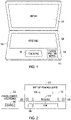
FIG. 1 is a block diagram of a personal computer having a combined wireless charging pad and fan motor according to an example embodiment. -
FIG. 2 is a block diagram of the combined wireless charging pad and fan motor ofFIG. 1 according to an example embodiment. -
FIG. 3 is a top view block diagram of a fan motor having additional magnets for creating a charging electromagnetic field according to an example embodiment. -
FIG. 4 is a flowchart illustrating a method for cooling an electronic device and generating a charging field via a cooling fan motor according to an example embodiment. -
FIG. 5 is a block schematic diagram of a computer system to implement one or more example embodiments. - In the following description, reference is made to the accompanying drawings that form a part hereof, and in which is shown by way of illustration specific embodiments which may be practiced. These embodiments are described in sufficient detail to enable those skilled in the art to practice the invention, and it is to be understood that other embodiments may be utilized and that structural, logical and electrical changes may be made without departing from the scope of the present invention. The following description of example embodiments is, therefore, not to be taken in a limited sense, and the scope of the present invention is defined by the appended claims.
- The functions or algorithms described herein may be implemented in software in one embodiment. The software may consist of computer executable instructions stored on computer readable media or computer readable storage device such as one or more non-transitory memories or other type of hardware based storage devices, either local or networked. Further, such functions correspond to modules, which may be software, hardware, firmware or any combination thereof. Multiple functions may be performed in one or more modules as desired, and the embodiments described are merely examples. The software may be executed on a digital signal processor, ASIC, microprocessor, or other type of processor operating on a computer system, such as a personal computer, server or other computer system, turning such computer system into a specifically programmed machine.
- The functionality can be configured to perform an operation using, for instance, software, hardware, firmware, or the like. For example, the phrase "configured to" can refer to a logic circuit structure of a hardware element that is to implement the associated functionality. The phrase "configured to" can also refer to a logic circuit structure of a hardware element that is to implement the coding design of associated functionality of firmware or software. The term "module" refers to a structural element that can be implemented using any suitable hardware (e.g., a processor, among others), software (e.g., an application, among others), firmware, or any combination of hardware, software, and firmware. The term, "logic" encompasses any functionality for performing a task. For instance, each operation illustrated in the flowcharts corresponds to logic for performing that operation. An operation can be performed using, software, hardware, firmware, or the like. The terms, "component," "system," and the like may refer to computer-related entities, hardware, and software in execution, firmware, or combination thereof. A component may be a process running on a processor, an object, an executable, a program, a function, a subroutine, a computer, or a combination of software and hardware. The term, "processor," may refer to a hardware component, such as a processing unit of a computer system.
- Furthermore, the claimed subject matter may be implemented as a method, apparatus, or article of manufacture using standard programming and engineering techniques to produce software, firmware, hardware, or any combination thereof to control a computing device to implement the disclosed subject matter. The term, "article of manufacture," as used herein is intended to encompass a computer program accessible from any computer-readable storage device or media. Computer-readable storage media can include, but are not limited to, magnetic storage devices, e.g., hard disk, floppy disk, magnetic strips, optical disk, compact disk (CD), digital versatile disk (DVD), smart cards, flash memory devices, among others. In contrast, computer-readable media, i.e., not storage media, may additionally include communication media such as transmission media for wireless signals and the like.
- Most thin computers already contain a flat, variable speed exhaust fan motor. The coils in such a motor create the same kinds of alternating electrical field as wireless charging circuits. The difference is that the frequency varies in the motor at about 5khz, and wireless charging works at about 140khz.
- With a small amount of physical rearrangement the inductive field coils from the motor are exposed as a charging pad. The windings on that side are altered to emit a higher frequency electrical field through a phase locked loop or through secondary interaction of the magnetic drive field with circumferential magnets.
-
FIG. 1 is a block diagram of adevice 100 having a combined wireless charging pad and fan motor, referred to as charging pad 110 (represented by a broken line) placed beneath anopen area 115 on a top interactive side ofdevice 100.Device 100 may be a laptop computer in some embodiments, and include akeyboard 120,touchpad 125, and display 130. Other devices having limited internal space yet an open area on a surface that is suitable for coming in close contact with a device to be wirelessly charged may alternatively make use of a combined wireless charging pad and fan motor. Placing the combined wireless charging pad and fan motor near the top interactive surface, allows thedevice 100 to be used while at the same time charging a battery powered device. - In various embodiments, the combined wireless charging pad and
fan motor 110 may be less than 5 cm in diameter. -
FIG. 2 is a block diagram of the combined wireless charging pad andfan motor 110 ofFIG. 1 according to an example embodiment. Portions of the combined wireless charging pad andfan motor 110 that emit electromagnetic fields are placed towards the top side ofdevice 100 instead of a board side in one embodiment to bring the emitted fields closer to the top side inopen area 115. - In one embodiment, the portions that emit electromagnetic fields comprise
coil windings 210 of a rotor or stator. The motor drives fan blades indicated at 212. Note that the fan blades are shown below thewindings 210, but may also be laterally spaced in a same plane about the windings in further embodiments. In one embodiment, thecoil windings 210 are increased to increase the field to enough to simultaneously turn the fan motor and to charge adevice 215 positioned proximate thewindings 210. Additional circumferentially disposed magnets 217 may be added to emit a higher frequency electrical field via interaction with the magnetic field created by thewindings 210. - A
detection plate 220 may be added on or near the case to detect the presence ofdevice 215 to be charged when placed near thecharging pad 110. - An inductive
soft iron plate 225 may be added near the motor coil to create the charging resonance. - A
backscatter modulation detector 230 may be added at the base of the motor power circuit. - In some embodiments, the motor and charger cannot run simultaneously. In these cases, a mode control implemented by a power controller and
electronics circuitry 235 may control which runs based on need for cooling weighed against the need for charging, which cooling needs taking precedence. -
Circuitry 235 may also run variablespeed control software 240 that runs the motor to increase the current and overlay a high frequency AC signal into the low-frequency motor driving DC when charging to obtain charging frequencies of approximately between about 110 and 205 kHz for the low power charging up to 5 watts and 80-300 kHz for the medium power charging. In one embodiment,circuitry 235 includes a phase locked loop to cause emission of desired charging frequencies from thewindings 210. - In a further embodiment,
detection plate 220 provides an indication to theelectronics 235 to indicate that the battery powereddevice 215 is in position for charging. Theelectronics 235 may then enter a charging mode to increase the speed of the motor to generate the desired frequency of electromagnetic field for charging the battery powereddevice 215. -
FIG. 3 is a top view block diagram of afan motor 300 having aseries magnets 310 arranged circumferentially aroundwindings 315 to generate a suitable electromagnetic field for charging a batter powered device. In one embodiment,motor 300 is shown as having a two-phasebrushless motor stator 320 supporting the windings. - In one embodiment, the coils are placed on the
stator 320 of the motor. In a further embodiment, the circumferential series ofmagnets 315 may be placed around the rotor of the motor. In further embodiments, thecharging pad 110 may be placed on a back side of theelectronic device 100. - An inductive plate, such as an inductive
soft iron plate 325 is added near or around themotor 300 to direct the generated charging field to the charging pad. -
FIG. 4 is a flowchart illustrating amethod 400 for cooling an electronic device and generating a charging field via a cooling fan motor according to an example embodiment.Method 400 includes generating an electromagnetic charging field at 410 with a cooling fan motor disposed within an electronic device. The electromagnetic field is directed to a charging area on a surface of a case containing electronics of the electronic device. At 420, a fan coupled to the cooling fan motor is driven to also cool the electronics. - In one embodiment, the cooling fan motor is controlled between a first mode having a low frequency for driving the fan and a second mode having a higher frequency for generating the electromagnetic charging field. The low frequency is approximately 5KHz, and the higher frequency is greater than 80KHz.
- In one embodiment, the electromagnetic charging field is generated via a series of magnets circumferentially disposed about a stator of the cooling fan motor. The field may be directed to the charging area by an inductive plate positioned about the cooling fan motor.
- The presence of a battery powered device on the charging area may be detected prior to generating the charging field.
-
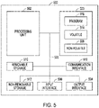
FIG. 5 is a block schematic diagram of acomputer system 500 to implement control actions and circuitry for controlling a fan motor to also or alternatively operate as a wireless charging device and for performing methods and algorithms according to example embodiments. All components need not be used in various embodiments. - One example computing device in the form of a
computer 500 may include aprocessing unit 502,memory 503,removable storage 510, andnon-removable storage 512. Although the example computing device is illustrated and described ascomputer 500, the computing device may be in different forms in different embodiments. For example, the computing device may instead be a smartphone, a tablet, smartwatch, smart storage device (SSD), or other computing device including the same or similar elements as illustrated and described with regard toFIG. 5 . Devices, such as smartphones, tablets, and smartwatches, are generally collectively referred to as mobile devices or user equipment. - Although the various data storage elements are illustrated as part of the
computer 500, the storage may also or alternatively include cloud-based storage accessible via a network, such as the Internet or server-based storage. Note also that an SSD may include a processor on which the parser may be run, allowing transfer of parsed, filtered data through I/O channels between the SSD and main memory. -
Memory 503 may includevolatile memory 514 andnon-volatile memory 508.Computer 500 may include - or have access to a computing environment that includes - a variety of computer-readable media, such asvolatile memory 514 andnon-volatile memory 508,removable storage 510 andnon-removable storage 512. Computer storage includes random access memory (RAM), read only memory (ROM), erasable programmable read-only memory (EPROM) or electrically erasable programmable read-only memory (EEPROM), flash memory or other memory technologies, compact disc read-only memory (CD ROM), Digital Versatile Disks (DVD) or other optical disk storage, magnetic cassettes, magnetic tape, magnetic disk storage or other magnetic storage devices, or any other medium capable of storing computer-readable instructions. -
Computer 500 may include or have access to a computing environment that includesinput interface 506,output interface 504, and acommunication interface 516.Output interface 504 may include a display device, such as a touchscreen, that also may serve as an input device. Theinput interface 506 may include one or more of a touchscreen, touchpad, mouse, keyboard, camera, one or more device-specific buttons, one or more sensors integrated within or coupled via wired or wireless data connections to thecomputer 500, and other input devices. The computer may operate in a networked environment using a communication connection to connect to one or more remote computers, such as database servers. The remote computer may include a personal computer (PC), server, router, network PC, a peer device or other common data flow network switch, or the like. The communication connection may include a Local Area Network (LAN), a Wide Area Network (WAN), cellular, Wi-Fi, Bluetooth, or other networks. According to one embodiment, the various components ofcomputer 500 are connected with asystem bus 520. - Computer-readable instructions stored on a computer-readable medium are executable by the
processing unit 502 of thecomputer 500, such as aprogram 518. Theprogram 518 in some embodiments comprises software to implement one or more methods described herein. A hard drive, CD-ROM, and RAM are some examples of articles including a non-transitory computer-readable medium such as a storage device. The terms computer-readable medium, machine readable medium, and storage device do not include carrier waves or signals to the extent carrier waves and signals are deemed too transitory. Storage can also include networked storage, such as a storage area network (SAN).Computer program 518 along with the workspace manager 522 may be used to causeprocessing unit 502 to perform one or more methods or algorithms described herein. - Although a few embodiments have been described in detail above, other modifications are possible. For example, the logic flows depicted in the figures do not require the particular order shown, or sequential order, to achieve desirable results. Other steps may be provided, or steps may be eliminated, from the described flows, and other components may be added to, or removed from, the described systems. Other embodiments may be within the scope of the following claims.
Claims (15)
- An electronic device comprising:a case for housing electronics;a fan supported within the case, the fan including:
a motor configured to drive fan blades and to generate an electromagnetic charging field, the motor positioned to provide the charging field to an open area outside the case comprising a charging pad. - The device of claim 1 and further comprising a series of magnets circumferentially disposed about a stator of the motor to generate the charging field.
- The device of claim 1 or 2 and further comprising a controller to control a speed of the motor to generate the charging field.
- The device of claim 3 wherein:the controller controls a mode of the motor to either operate in a cooling mode or a charging mode; orthe cooling mode has frequency of about 5KHz and the charging field has a frequency greater than 80KHz.
- The device of any of claims 1 to 4 wherein the charging field has a frequency of between 80 to 300 KHz.
- The device of any of claims 1 to 5 and further comprising phase lock loop electronics to control the frequency of the charging field.
- The device of any of claims 1 to 6 and further comprising an inductive iron plate disposed about coil windings of the motor to create a charging resonance with a device being charged.
- The device of any of claims 1 to 7 and further comprising a detection plate to detect a device to be charged.
- The device of any of claims 1 to 8 wherein the motor comprises coil windings having an increased number of windings to generate the charging field.
- The device of any of claims 1 to 9 and further comprising a backscatter modulation detector supported at a base of the motor.
- A method comprising:generating an electromagnetic charging field with a cooling fan motor disposed within an electronic device, the electromagnetic field directed to a charging area on a surface of a case containing electronics of the electronic device; anddriving a fan coupled to the cooling fan motor to cool the electronics.
- The method of claim 11 and further comprising controlling the cooling fan motor between a first mode having a low frequency for driving the fan and a second mode having a higher frequency for generating the electromagnetic charging field, and
optionally wherein the low frequency is approximately 5KHz, and the higher frequency is greater than 80KHz. - The method of claim 11 or 12, wherein:the electromagnetic charging field is generated via a series of magnets circumferentially disposed about a stator of the cooling fan motor; orthe field is directed to the charging area by an inductive plate positioned about the cooling fan motor; orthe method further comprises detecting the presence of a battery powered device on the charging area prior to generating the charging field.
- A device comprising:a processor; anda memory device coupled to the processor and having a program stored thereon for execution by the processor to perform operations comprising:generating an electromagnetic charging field with a cooling fan motor disposed within an electronic device, the electromagnetic field directed to a charging area on a surface of a case containing electronics of the electronic device; anddriving a fan coupled to the cooling fan motor to cool the electronics.
- The device of claim 14 wherein the operations further comprise controlling the cooling fan motor between a first mode having a low frequency for driving the fan and a second mode having a higher frequency for generating the electromagnetic charging field, and
optionally wherein the low frequency is approximately 5KHz, and the higher frequency is greater than 80KHz.
Applications Claiming Priority (1)
| Application Number | Priority Date | Filing Date | Title |
|---|---|---|---|
| US17/214,140 US11520386B2 (en) | 2021-03-26 | 2021-03-26 | Fan motor for wireless charging |
Publications (1)
| Publication Number | Publication Date |
|---|---|
| EP4064809A1 true EP4064809A1 (en) | 2022-09-28 |
Family
ID=80461767
Family Applications (1)
| Application Number | Title | Priority Date | Filing Date |
|---|---|---|---|
| EP22158752.0A Pending EP4064809A1 (en) | 2021-03-26 | 2022-02-25 | Fan motor for wireless charging |
Country Status (3)
| Country | Link |
|---|---|
| US (1) | US11520386B2 (en) |
| EP (1) | EP4064809A1 (en) |
| CN (1) | CN115033056B (en) |
Families Citing this family (1)
| Publication number | Priority date | Publication date | Assignee | Title |
|---|---|---|---|---|
| US11696420B2 (en) * | 2021-07-08 | 2023-07-04 | Eaton Intelligent Power Limited | Cooling device for circuit breakers using parasitic magnetic fields based forced air flow generator |
Citations (2)
| Publication number | Priority date | Publication date | Assignee | Title |
|---|---|---|---|---|
| US10640001B2 (en) * | 2016-11-01 | 2020-05-05 | Hyundai Motor Company | Wireless power transfer method using field winding and vehicle assembly and electric vehicle using the same |
| US20200201402A1 (en) * | 2018-12-24 | 2020-06-25 | Samsung Electronics Co., Ltd. | Cooler with wireless charging function for mobile electronic device |
Family Cites Families (26)
| Publication number | Priority date | Publication date | Assignee | Title |
|---|---|---|---|---|
| US5135363A (en) * | 1982-11-09 | 1992-08-04 | Papst-Motoren Gmbh & Co. Kg | Miniaturized direct current fan |
| JPH05254455A (en) * | 1992-03-13 | 1993-10-05 | Isuzu Motors Ltd | Electric power steering device |
| US6388346B1 (en) * | 1998-10-14 | 2002-05-14 | Air Concepts, Inc. | Axial fluid flow inducing device with multiple magnetically driven impellers |
| US6194798B1 (en) * | 1998-10-14 | 2001-02-27 | Air Concepts, Inc. | Fan with magnetic blades |
| JP2000355402A (en) * | 1999-06-16 | 2000-12-26 | Nippon Yusoki Co Ltd | Control device and method for automatic guided vehicle |
| US6606578B1 (en) * | 2001-03-01 | 2003-08-12 | Lockheed Martin Corporation | System and method for electromagnetic propulsion fan |
| US6527522B2 (en) * | 2001-07-03 | 2003-03-04 | Yen Sun Technology Corp. | Heat dissipation fan structure |
| US6670737B2 (en) * | 2002-01-02 | 2003-12-30 | Yen Sun Technology Corp. | Motor having removable poles with positioning structures |
| US6896492B2 (en) * | 2002-08-28 | 2005-05-24 | Motorola, Inc. | Magnetically driven air moving apparatus, with magnetically tipped fan blades and a single field coil and core |
| US7121697B2 (en) * | 2004-09-01 | 2006-10-17 | Sam Hsu | Illumination device for computer fan |
| US20060120063A1 (en) * | 2004-12-02 | 2006-06-08 | Power Cooler Enterprise Co., Ltd. | Brightness controllable luminescent fan |
| TWI399012B (en) * | 2010-11-12 | 2013-06-11 | Yen Sun Technology Corp | Motor stator |
| DE102011112821B4 (en) * | 2011-09-12 | 2013-06-27 | Brose Fahrzeugteile GmbH & Co. Kommanditgesellschaft, Würzburg | Electric motor, in particular radiator fan motor |
| KR101977088B1 (en) * | 2013-01-08 | 2019-05-10 | 엘지전자 주식회사 | Wireless power transmitter |
| DE102014207719A1 (en) * | 2014-04-24 | 2015-10-29 | Bayerische Motoren Werke Aktiengesellschaft | Scalable inductive charging station |
| KR20160100754A (en) * | 2015-02-16 | 2016-08-24 | 엘지이노텍 주식회사 | Apparatus and method for receiving wireless power and terminal |
| US10718339B2 (en) * | 2015-09-03 | 2020-07-21 | Apple Inc. | Peripheral drive centrifugal fan |
| US10511201B2 (en) * | 2016-03-25 | 2019-12-17 | Amotech Co., Ltd. | Stacking-type stator using multilayer printed circuit board, and single-phase motor and cooling fan using same |
| KR101916265B1 (en) * | 2016-04-07 | 2018-11-07 | 주식회사 아모텍 | Slim Type Stator, Sensorless Type Single Phase Motor and Cooling Fan Using the Same |
| KR102713456B1 (en) * | 2017-02-17 | 2024-10-07 | 삼성전자주식회사 | Blowing apparatus and docking apparatus including the same |
| KR102377279B1 (en) * | 2017-03-28 | 2022-03-23 | 삼성전자주식회사 | Electronic device including cooling function and controlling method thereof |
| KR102400745B1 (en) * | 2017-03-28 | 2022-05-23 | 삼성전자주식회사 | Docking station for electronic device |
| US20190115781A1 (en) * | 2017-10-16 | 2019-04-18 | Daobin Feng | Wireless charger |
| CN208236712U (en) * | 2018-05-14 | 2018-12-14 | 东莞虹盛电子科技有限公司 | A fan with a wireless charging structure and displaying characters and lights |
| US20200091755A1 (en) * | 2018-09-19 | 2020-03-19 | Apple Inc. | Inductive charging dock |
| US20220069595A1 (en) * | 2020-08-27 | 2022-03-03 | Koi Charging LLC | Laptop case with charging pad |
-
2021
- 2021-03-26 US US17/214,140 patent/US11520386B2/en active Active
-
2022
- 2022-02-25 EP EP22158752.0A patent/EP4064809A1/en active Pending
- 2022-03-25 CN CN202210307930.6A patent/CN115033056B/en active Active
Patent Citations (2)
| Publication number | Priority date | Publication date | Assignee | Title |
|---|---|---|---|---|
| US10640001B2 (en) * | 2016-11-01 | 2020-05-05 | Hyundai Motor Company | Wireless power transfer method using field winding and vehicle assembly and electric vehicle using the same |
| US20200201402A1 (en) * | 2018-12-24 | 2020-06-25 | Samsung Electronics Co., Ltd. | Cooler with wireless charging function for mobile electronic device |
Non-Patent Citations (1)
| Title |
|---|
| RALLABANDI VANDANA ET AL: "An Integrated Electric Vehicle Drive Motor and Wireless Charger", 2023 IEEE WIRELESS POWER TECHNOLOGY CONFERENCE AND EXPO (WPTCE), 4 June 2023 (2023-06-04), pages 1 - 5, XP093373493, ISBN: 979-8-35-033737-2, DOI: 10.1109/WPTCE56855.2023.10215691 * |
Also Published As
| Publication number | Publication date |
|---|---|
| CN115033056A (en) | 2022-09-09 |
| US20220308644A1 (en) | 2022-09-29 |
| US11520386B2 (en) | 2022-12-06 |
| CN115033056B (en) | 2024-12-13 |
Similar Documents
| Publication | Publication Date | Title |
|---|---|---|
| US20200343751A1 (en) | Wireless Charging Systems with Multiple Power Receiving Devices | |
| CN107949970B (en) | Wireless charging method and device | |
| EP3627653A1 (en) | Inductive charging dock | |
| US20160181849A1 (en) | System and method for thermal management in wireless charging devices | |
| CN105474508B (en) | For the device and method of electric power detection to be lost | |
| US10159118B2 (en) | Method and device for determining the suitability of a cookware for a corresponding induction coil of an induction cooking hob | |
| KR102644295B1 (en) | Apparatus for charging power wirelessly and method thereof | |
| EP3304681B1 (en) | Wireless power transfer using a field altering circuit | |
| KR20140138389A (en) | Apparatus and method for wireless power transmission | |
| CN109564454B (en) | Power-based device thermal management | |
| KR102066369B1 (en) | Apparatus and method for wireless power charging of subsequent receivers | |
| US9774212B2 (en) | Wireless charging device and wireless charging method for charging electronic device | |
| US10076067B2 (en) | System and method of controlling an air mover | |
| US11520386B2 (en) | Fan motor for wireless charging | |
| WO2016078573A1 (en) | Recyclable logistical apparatus and management method thereof | |
| US10439403B2 (en) | Smart bag with display for charging a device | |
| US20180152058A1 (en) | Wireless charging method and electronic device supporting same | |
| US10860072B2 (en) | Expected and detected air mover configurations | |
| KR102700029B1 (en) | Electronic device including a plurality of wireless charge coils and operating method thereof | |
| US20210351630A1 (en) | System and method for wireless power transmission | |
| KR20180101890A (en) | Wireless power transmitter and method for operating thereof | |
| US9823636B2 (en) | Systems and methods for parallel feedback temperature control | |
| KR20170056318A (en) | Electrostatic induction device for performing power generating function | |
| CN107615635B (en) | Reconfigurable power converter | |
| CN108282117A (en) | A kind of DC fan starts method, control circuit and air conditioner |
Legal Events
| Date | Code | Title | Description |
|---|---|---|---|
| PUAI | Public reference made under article 153(3) epc to a published international application that has entered the european phase |
Free format text: ORIGINAL CODE: 0009012 |
|
| STAA | Information on the status of an ep patent application or granted ep patent |
Free format text: STATUS: THE APPLICATION HAS BEEN PUBLISHED |
|
| AK | Designated contracting states |
Kind code of ref document: A1 Designated state(s): AL AT BE BG CH CY CZ DE DK EE ES FI FR GB GR HR HU IE IS IT LI LT LU LV MC MK MT NL NO PL PT RO RS SE SI SK SM TR |
|
| STAA | Information on the status of an ep patent application or granted ep patent |
Free format text: STATUS: REQUEST FOR EXAMINATION WAS MADE |
|
| 17P | Request for examination filed |
Effective date: 20230322 |
|
| RBV | Designated contracting states (corrected) |
Designated state(s): AL AT BE BG CH CY CZ DE DK EE ES FI FR GB GR HR HU IE IS IT LI LT LU LV MC MK MT NL NO PL PT RO RS SE SI SK SM TR |
|
| STAA | Information on the status of an ep patent application or granted ep patent |
Free format text: STATUS: EXAMINATION IS IN PROGRESS |
|
| 17Q | First examination report despatched |
Effective date: 20260312 |