EP4064792B1 - Stirnlampe, die mit einer verbesserten dynamischen beleuchtung ausgestattet ist - Google Patents
Stirnlampe, die mit einer verbesserten dynamischen beleuchtung ausgestattet ist Download PDFInfo
- Publication number
- EP4064792B1 EP4064792B1 EP21164886.0A EP21164886A EP4064792B1 EP 4064792 B1 EP4064792 B1 EP 4064792B1 EP 21164886 A EP21164886 A EP 21164886A EP 4064792 B1 EP4064792 B1 EP 4064792B1
- Authority
- EP
- European Patent Office
- Prior art keywords
- light
- headlamp
- accelerometer
- lut
- control module
- Prior art date
- Legal status (The legal status is an assumption and is not a legal conclusion. Google has not performed a legal analysis and makes no representation as to the accuracy of the status listed.)
- Active
Links
Images


Classifications
-
- F—MECHANICAL ENGINEERING; LIGHTING; HEATING; WEAPONS; BLASTING
- F21—LIGHTING
- F21L—LIGHTING DEVICES OR SYSTEMS THEREOF, BEING PORTABLE OR SPECIALLY ADAPTED FOR TRANSPORTATION
- F21L4/00—Electric lighting devices with self-contained electric batteries or cells
-
- F—MECHANICAL ENGINEERING; LIGHTING; HEATING; WEAPONS; BLASTING
- F21—LIGHTING
- F21V—FUNCTIONAL FEATURES OR DETAILS OF LIGHTING DEVICES OR SYSTEMS THEREOF; STRUCTURAL COMBINATIONS OF LIGHTING DEVICES WITH OTHER ARTICLES, NOT OTHERWISE PROVIDED FOR
- F21V21/00—Supporting, suspending, or attaching arrangements for lighting devices; Hand grips
- F21V21/08—Devices for easy attachment to any desired place, e.g. clip, clamp, magnet
- F21V21/084—Head fittings
-
- F—MECHANICAL ENGINEERING; LIGHTING; HEATING; WEAPONS; BLASTING
- F21—LIGHTING
- F21V—FUNCTIONAL FEATURES OR DETAILS OF LIGHTING DEVICES OR SYSTEMS THEREOF; STRUCTURAL COMBINATIONS OF LIGHTING DEVICES WITH OTHER ARTICLES, NOT OTHERWISE PROVIDED FOR
- F21V23/00—Arrangement of electric circuit elements in or on lighting devices
- F21V23/003—Arrangement of electric circuit elements in or on lighting devices the elements being electronics drivers or controllers for operating the light source, e.g. for a LED array
-
- F—MECHANICAL ENGINEERING; LIGHTING; HEATING; WEAPONS; BLASTING
- F21—LIGHTING
- F21V—FUNCTIONAL FEATURES OR DETAILS OF LIGHTING DEVICES OR SYSTEMS THEREOF; STRUCTURAL COMBINATIONS OF LIGHTING DEVICES WITH OTHER ARTICLES, NOT OTHERWISE PROVIDED FOR
- F21V23/00—Arrangement of electric circuit elements in or on lighting devices
- F21V23/04—Arrangement of electric circuit elements in or on lighting devices the elements being switches
- F21V23/0442—Arrangement of electric circuit elements in or on lighting devices the elements being switches activated by means of a sensor, e.g. motion or photodetectors
- F21V23/0464—Arrangement of electric circuit elements in or on lighting devices the elements being switches activated by means of a sensor, e.g. motion or photodetectors the sensor sensing the level of ambient illumination, e.g. dawn or dusk sensors
-
- F—MECHANICAL ENGINEERING; LIGHTING; HEATING; WEAPONS; BLASTING
- F21—LIGHTING
- F21V—FUNCTIONAL FEATURES OR DETAILS OF LIGHTING DEVICES OR SYSTEMS THEREOF; STRUCTURAL COMBINATIONS OF LIGHTING DEVICES WITH OTHER ARTICLES, NOT OTHERWISE PROVIDED FOR
- F21V23/00—Arrangement of electric circuit elements in or on lighting devices
- F21V23/04—Arrangement of electric circuit elements in or on lighting devices the elements being switches
- F21V23/0442—Arrangement of electric circuit elements in or on lighting devices the elements being switches activated by means of a sensor, e.g. motion or photodetectors
- F21V23/0492—Arrangement of electric circuit elements in or on lighting devices the elements being switches activated by means of a sensor, e.g. motion or photodetectors the sensor detecting a change in orientation, a movement or an acceleration of the lighting device, e.g. a tilt switch
-
- G—PHYSICS
- G08—SIGNALLING
- G08B—SIGNALLING SYSTEMS, e.g. PERSONAL CALLING SYSTEMS; ORDER TELEGRAPHS; ALARM SYSTEMS
- G08B21/00—Alarms responsive to a single specified undesired or abnormal condition and not otherwise provided for
- G08B21/02—Alarms for ensuring the safety of persons
- G08B21/04—Alarms for ensuring the safety of persons responsive to non-activity, e.g. of elderly persons
- G08B21/0407—Alarms for ensuring the safety of persons responsive to non-activity, e.g. of elderly persons based on behaviour analysis
- G08B21/043—Alarms for ensuring the safety of persons responsive to non-activity, e.g. of elderly persons based on behaviour analysis detecting an emergency event, e.g. a fall
-
- G—PHYSICS
- G08—SIGNALLING
- G08B—SIGNALLING SYSTEMS, e.g. PERSONAL CALLING SYSTEMS; ORDER TELEGRAPHS; ALARM SYSTEMS
- G08B5/00—Visible signalling systems, e.g. visible personal calling systems or remote indication of seats occupied
- G08B5/22—Visible signalling systems, e.g. visible personal calling systems or remote indication of seats occupied using electric transmission; using electromagnetic transmission
- G08B5/36—Visible signalling systems, e.g. visible personal calling systems or remote indication of seats occupied using electric transmission; using electromagnetic transmission using visible light sources
-
- H—ELECTRICITY
- H05—ELECTRIC TECHNIQUES NOT OTHERWISE PROVIDED FOR
- H05B—ELECTRIC HEATING; ELECTRIC LIGHT SOURCES NOT OTHERWISE PROVIDED FOR; CIRCUIT ARRANGEMENTS FOR ELECTRIC LIGHT SOURCES, IN GENERAL
- H05B45/00—Circuit arrangements for operating light-emitting diodes [LED]
- H05B45/10—Controlling the intensity of the light
- H05B45/12—Controlling the intensity of the light using optical feedback
-
- H—ELECTRICITY
- H05—ELECTRIC TECHNIQUES NOT OTHERWISE PROVIDED FOR
- H05B—ELECTRIC HEATING; ELECTRIC LIGHT SOURCES NOT OTHERWISE PROVIDED FOR; CIRCUIT ARRANGEMENTS FOR ELECTRIC LIGHT SOURCES, IN GENERAL
- H05B47/00—Circuit arrangements for operating light sources in general, i.e. where the type of light source is not relevant
- H05B47/10—Controlling the light source
- H05B47/105—Controlling the light source in response to determined parameters
- H05B47/11—Controlling the light source in response to determined parameters by determining the brightness or colour temperature of ambient light
-
- H—ELECTRICITY
- H05—ELECTRIC TECHNIQUES NOT OTHERWISE PROVIDED FOR
- H05B—ELECTRIC HEATING; ELECTRIC LIGHT SOURCES NOT OTHERWISE PROVIDED FOR; CIRCUIT ARRANGEMENTS FOR ELECTRIC LIGHT SOURCES, IN GENERAL
- H05B47/00—Circuit arrangements for operating light sources in general, i.e. where the type of light source is not relevant
- H05B47/10—Controlling the light source
- H05B47/105—Controlling the light source in response to determined parameters
- H05B47/115—Controlling the light source in response to determined parameters by determining the presence or movement of objects or living beings
-
- H—ELECTRICITY
- H05—ELECTRIC TECHNIQUES NOT OTHERWISE PROVIDED FOR
- H05B—ELECTRIC HEATING; ELECTRIC LIGHT SOURCES NOT OTHERWISE PROVIDED FOR; CIRCUIT ARRANGEMENTS FOR ELECTRIC LIGHT SOURCES, IN GENERAL
- H05B47/00—Circuit arrangements for operating light sources in general, i.e. where the type of light source is not relevant
- H05B47/10—Controlling the light source
- H05B47/165—Controlling the light source following a pre-assigned programmed sequence; Logic control [LC]
-
- F—MECHANICAL ENGINEERING; LIGHTING; HEATING; WEAPONS; BLASTING
- F21—LIGHTING
- F21Y—INDEXING SCHEME ASSOCIATED WITH SUBCLASSES F21K, F21L, F21S and F21V, RELATING TO THE FORM OR THE KIND OF THE LIGHT SOURCES OR OF THE COLOUR OF THE LIGHT EMITTED
- F21Y2115/00—Light-generating elements of semiconductor light sources
- F21Y2115/10—Light-emitting diodes [LED]
-
- G—PHYSICS
- G08—SIGNALLING
- G08B—SIGNALLING SYSTEMS, e.g. PERSONAL CALLING SYSTEMS; ORDER TELEGRAPHS; ALARM SYSTEMS
- G08B5/00—Visible signalling systems, e.g. visible personal calling systems or remote indication of seats occupied
- G08B5/22—Visible signalling systems, e.g. visible personal calling systems or remote indication of seats occupied using electric transmission; using electromagnetic transmission
-
- H—ELECTRICITY
- H05—ELECTRIC TECHNIQUES NOT OTHERWISE PROVIDED FOR
- H05B—ELECTRIC HEATING; ELECTRIC LIGHT SOURCES NOT OTHERWISE PROVIDED FOR; CIRCUIT ARRANGEMENTS FOR ELECTRIC LIGHT SOURCES, IN GENERAL
- H05B47/00—Circuit arrangements for operating light sources in general, i.e. where the type of light source is not relevant
- H05B47/10—Controlling the light source
- H05B47/17—Operational modes, e.g. switching from manual to automatic mode or prohibiting specific operations
Definitions
- the present invention relates to the field of headlamps equipped with so-called Reactive Lighting technology, and in particular a headlamp comprising an accelerometric sensor.
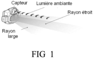
- the applicant for the present patent application has marketed a portable lamp, of the headlamp type, equipped with so-called reactive or dynamic lighting, the operating principle of which is illustrated in the figure 1 .
- This headlamp features an electronic circuit with a sensor that analyzes the external brightness to instantly deliver a set lighting power and beam shape optimal for the situation.
- This type of lamp has proven to be particularly suitable for committed and intensive sports because it relieves the user of the manual mode adjustments that would be necessary to switch between different beam power thresholds.
- the user can observe or examine an object at short distance (reading a map, making a rope knot or pitching a tent for example) and the lamp can protect a Very wide and low-power light beam, automatically set to a minimum threshold value thanks to this dynamic lighting technique.
- the lighting automatically adapts to the distance of the object.
- the beam becomes mixed: wide at the level of the feet and focused to see a few meters and anticipate the relief.
- the user when in a distant vision situation, the user raises his head to see into the distance - for example to look for a beacon during a run or a relay attached to a wall, the lighting power increases considerably and the beam becomes focused to best assist the user of the lamp.
- Reactive Lighting reactive or dynamic lighting technology
- this reactive or dynamic lighting technology undeniably constitutes a significant advance in the field of headlamps, and more generally of portable lighting, in particular in that it allows the lighting to be constantly adapted to the lighting conditions.
- practitioners have noted drawbacks in certain very specific situations. Indeed, in so-called trail or running activities, the presence of numerous reflective surfaces on shoes, technical clothing and signage causes pumping phenomena in the projected light, thus degrading the quality of the lighting and creating an area of discomfort for the user.
- the minimum level of light may prove to be insufficient in practice to guarantee safe lighting when crossing a luminous or natural obstacle (car headlights, tree branches, etc.).
- US 2020/187331 A1 (BERTKEN DENNIS [US] ET AL ) describes a lantern or flashlight type lighting device having an accelerometer, but does not describe a headlamp, nor does it describe or suggest the use of a headlamp control module configured to select an activity profile chosen from a set of predetermined physical activity profiles.
- This prior art does not describe or suggest the use of a LUT lookup table providing at least one value or parameter for adjusting the power regulation of the lamp.
- WO 2012/146256 A2 LIGHTEN APS [DK], PEDERSEN STEEN HVIDTFELDT HESSELLUND [DK] describes an ambient lighting system for initiating a circadian or well-being change.
- This prior art describes the use of a human or mammal activity sensor or detector and the use of an accelerometer with processing means to determine whether the person is running, walking, sitting, typing, lying down, etc.
- this document does not describe or suggest the use of the accelerometer and the light source within a single component that constitutes a headlamp attached to a user's head.
- US 2016/258599 A1 (GENTHON FABIEN [FR]) describes a headlamp with a circuit for adjusting the geometry of the light beam.
- the present invention aims to provide a significant improvement to dynamic lighting technology by making it possible to take into consideration specific lighting situations requiring additional lighting.
- Another object of the present invention is to provide a headlamp having reactive or dynamic type light regulation having improved adjustment of light power.
- the control module further comprises an accelerometer configured to provide at regular intervals data representative of an acceleration of the headlamp along at least one horizontal axis and one vertical axis; and wherein the control module comprises a circuit configured to store and process accelerometry data in order to select a physical activity profile chosen from a set of predetermined physical activity profiles stored in a memory.
- the selected physical activity profile is then used as an input pointer to read a LUT lookup table stored in an internal memory of the lamp, and which provides at least one value or parameter used to generate information or the control signal setting the light output.
- a LUT lookup table stored in an internal memory of the lamp, and which provides at least one value or parameter used to generate information or the control signal setting the light output.
- the set of predetermined accelerometer profiles include profiles representative of walking, running and cycling.
- the power of the light beam set by the control unit varies between a low threshold and a high threshold
- the low threshold is set by a value that is extracted directly from the LUT lookup table from the automatically selected profile.
- the processing of the accelerometer data allowing the selection of the predetermined profile uses a statistical processing method based on a calculation of the variance of the accelerometer data along the two horizontal axes and along the vertical axis.
- the invention also allows the production of a light regulation method for a headlamp as defined in claim 10.
- the data extracted from the LUT table makes it possible to define a minimum threshold of luminous power and a specific geometry of the light beam chosen between a wide beam, a pointed beam and/or both.
- the lamp is a headlamp configured to process accelerometer data to detect a user's fall in addition to their physical activity, and configured to communicate with a mobile phone for the purpose of transmitting an alert message.
- control module in the event of a fall, is configured to command a light alert sequence aimed at calling for help.
- the light power regulation mechanism is arranged so as to integrate, in addition to the information emanating from the brightness sensor, other complementary information generated by an accelerometric sensor providing acceleration signals on one or more axes X1, Y1 or Z1.
- a specific algorithm which will be described in detail below, makes it possible to set lighting thresholds generated by the light power regulation system, and in particular a minimum lighting threshold.
- FIG. 2 illustrates the general architecture of an embodiment of a lamp 100 - assumed to be frontal - comprising a reactive or dynamic regulation system of the light intensity based on a sensor 120 making it possible to measure the ambient brightness and/or a part of the flux reflected by the lighting of the frontal lamp.
- the lamp 100 also comprises an accelerometric sensor, and preferably a three-dimensional (3D) acceleration sensor 110 making it possible to generate accelerometric information along at least one axis and preferably three axes X1, Y1, Z1 in particular illustrated in the figure. figure 8 , the X1 and Z1 axes being horizontal and the Y1 axis being vertical.
- an accelerometric sensor and preferably a three-dimensional (3D) acceleration sensor 110 making it possible to generate accelerometric information along at least one axis and preferably three axes X1, Y1, Z1 in particular illustrated in the figure. figure 8 , the X1 and Z1 axes being horizontal and the Y1 axis being vertical.
- the lamp 100 comprises a power module 210 associated with a control module 220 and a lighting unit 230 comprising at least one light-emitting diode LED and, optionally, a transceiver module 240 coupled to the control module and a battery module 250 also coupled to the control module 220.
- the lighting unit 230 comprises a single LED diode 231 with its power supply circuit 232 connected to the power module 210.
- the LED diode(s) may be associated with a specific focal optic 233 making it possible to ensure collimation of the generated light beam.
- the power supply of the LED diode 231 via the circuit 232 is carried out by the power module under the control of information or a control signal generated by the control module 220 via a link which may take the form of a conductor or a set of conductors constituting a bus.
- a link which may take the form of a conductor or a set of conductors constituting a bus.
- the figure shows more particularly the particular example of a conductor 225.
- the power module 210 specifically comprises all the components that are conventionally found in an LED lighting lamp for producing a high-intensity light beam, and generally based on Pulse Width Modulation (PWM), well known to a person skilled in the art and similar to that found in class D audio circuits.
- PWM Pulse Width Modulation
- This PWM modulation is controlled by means of the control signal 225 generated by the control module 220.
- the term " signal " mentioned above refers to an electrical quantity - current or voltage - making it possible to cause the control of the power module, and in particular the PWM modulation used to supply current to the LED diode 231.
- control signal 225 any " control information ", for example logic information stored in a register and transmitted as has been said by any means suitable for the power module 210 for the purpose of controlling the emission power of the light beam.
- the control signal can therefore be emitted on different media depending on whether it is a signal or information.
- These media can be a bus-type communication line coupling the control module and the power module or a simple electronic circuit for transferring a control voltage or intensity.
- the two control and power modules are integrated into the same module or integrated circuit.
- control signal 225 this includes without distinction the embodiments using an electrical control quantity - current or voltage - as well as the embodiments in which the control is carried out by means of logic information transmitted within the power circuit. For this reason, we will hereinafter speak without distinction of control signal or information .
- control module 220 comprises a processor 221 as well as volatile memories 222 of the RAM type and non-volatile (flash, EEPROM) 223 as well as one or more input/output circuits 224.
- volatile memories 222 of the RAM type
- non-volatile (flash, EEPROM) 223 as well as one or more input/output circuits 224.
- the RAM and non-volatile memories are intended for storing data and micro-program or firmware instructions.
- the non-volatile memory 223 is also used for storing data representative of physical activity profiles which will be used in conjunction with the accelerometer data provided by the accelerometer sensor 110 as will be described later.
- the headlamp also includes a battery module 250 having a controller 252 and a battery 251, for example of the Ion-Lithium type.
- control module 220 can access each of the other modules present in the lamp, and in particular the power module 210, the battery module 250, the two brightness sensors 120 and accelerometer 110 as well as, where appropriate, the communication module 240 allowing two-way (upstream - downstream) wireless communication with a smartphone 300 or any other wireless communication device.
- Access of the control module 220 to the various components of the headlamp may take various forms, either by means of specific circuits and/or conductors or a set of conductors forming a bus.
- the link 225 is shown in the figure 2 in the form of a conductor while a real data/address/command bus 226 is used for the exchange of information between the control module 220, the battery module 250 and the transmitter/receiver module 240.
- control module 220 can both read and collect information contained in each of these modules and/or conversely, transfer information, data and/or commands there, as will become more clear in the remainder of the presentation.
- control module 220 can send to the power module a control signal as represented by the signal transmitted on the link 225 and, more generally, can read the current value of the supply current of the diode 231 passing via the conductors 232 (via circuits and/or buses not shown in the figure).
- control module 220 can access the battery module 250 via the bus 226 to read either the different voltage values (depending on the charge or discharge cycle in progress) at the terminals thereof and/or the value of the intensity delivered in order to be able to calculate a state of charge (SOC or State Of Charge in English literature).
- SOC State Of Charge
- the control module 220 comprises a communication module 240 enabling a wireless bidirectional connection with a mobile information processing system or mobile telephone 300.
- the transmitter and the receiver will be compatible with the Bluetooth standard, preferably with the Bluetooth 4.0 Low energy standard.
- the WIFI or IEEE802.11 standard will be adopted instead.
- the module 240 comprises a baseband unit (not illustrated) coupled to a receiver and a wireless transmitter, enabling an uplink communication channel to be organized towards the mobile telephone 300 and, in the opposite direction, a downlink communication channel towards this same telephone.
- the communication module 240 may be required to perform various processing operations, in series or in parallel, on the digital representation of the signal received and to be transmitted, and in particular, filtering, statistical calculation, demodulation, channel coding/decoding operations making it possible to make the communication robust to noise, etc.
- processing operations are well known in the field of signal processing, particularly when it comes to isolating a particular component of a signal, likely to carry digital information, and it will not be necessary here to weigh down the description.
- the processor 221 is therefore responsible for interpreting the packets received as well as formatting packets for transmission according to a format specific to the standard used. Thus, in the case of the Bluetooth Low Energy standard, these packets will have a structure around the standardized Generic Attribute Profile (GATT) that will not be detailed here. Depending on the interpretation of the data bits included in the packets received, the processor will reconstruct any information or commands received on the downlink from the mobile information processing system 300. Having interpreted this information or commands, the processor 221 will then relay or convert this information or command to the module concerned.
- GATT Generic Attribute Profile
- the processor 221 identifies commands for the power module 210 in order to modify the light intensity and in response to this identification is capable of generating control information on the conductor 225 intended for the power module 210 so that the latter proceeds to modify the light intensity generated by the lighting unit 230.
- processor 221 may also identify read requests issued by the associated mobile information processing system 300 so that the headlamp sends certain parameters to the telephone 300 on the uplink.
- These requests can thus be a request for the state of charge of the battery or the value of the current light power.
- the processor 221 will retrieve the necessary information directly from the module concerned and after having carried out any additional calculations on this information to obtain the final required information (in the case of the state of charge for example as seen above), will format a corresponding data packet for transmission by the transceiver module 240.
- FIG. 2 describes a basic embodiment, and that many other embodiments are possible and within the reach of a person skilled in the art.
- other modules may be added within the headlamp and these modules will also be coupled to the processor 221 via the bus 226 for example.
- These modules will then also be able to exchange data or commands in uplink or downlink with the associated mobile information processing system 300 which will then be able to communicate with the headlamp and transmit various configuration commands to it by means of a dedicated application running on the smartphone.
- This dedicated application then makes it possible to coordinate the various functionalities of the headlamp by offering in particular a user-friendly interface with the user by means of which the latter can either enter operating parameters or directly control the headlamp or select different options for the functionalities offered.
- the control module 220 of the headlamp 100 implements a dynamic or reactive lighting technique.
- This technique consists of substituting the well-known manual adjustment modes - based on various preset light power values such as low , medium or high , a more automatic technique allowing the adjustment of the light power to be left to the control module 220 and more specifically to a regulation algorithm executed by the processor 221 under the control of a regulation micro-software stored in non-volatile memory 223.
- the processor 221 adjusts the light power according to the value of the ambient brightness measured by the sensor 120, for example by selecting a value chosen from a set of N predefined threshold values.
- a mechanism of regulation is therefore similar to a mechanism for adjusting by discrete steps within a finite set of power values, allowing the control module 220 to control the headlamp by successively moving from one adjustment value to another value chosen from the set of predetermined values.
- the reactive or dynamic brightness mechanism therefore allows the automatic adjustment of the headlamp to the correct value within the N predetermined values.
- the geometry of the light beam can be adjusted automatically by selecting, via the control module 220, a diffusion mode chosen from a set of several predetermined modes: for example wide , narrow , or both at the same time.
- a person skilled in the art may envisage a more sophisticated regulation mechanism based on a real servocontrol integrating the brightness value within a feedback loop which may be linear or not, in order to set the power of the light beam generated by the module 230.
- error correction mechanisms may be appropriately integrated within the feedback loop, in particular a proportional (P), proportional-integral (PI), or even Proportional Integral Differential (PID) correction, etc., used with appropriate parameters.
- the regulation of dynamic or reactive lighting can be advantageously improved by introducing an exploitation of the accelerometer data ⁇ x, ⁇ y and ⁇ z generated by the three-dimensional accelerometer sensor 110, as will now be described.
- the three-dimensional accelerometer module 110 provides accelerometer signals ⁇ x, ⁇ y and ⁇ z along three trigonometric axes X1, Y1 and Z1. As shown in the figure 8 , the X1 and Z1 axes are horizontal while the Y1 axis is a vertical axis and, moreover, the X1 and Y1 axes are arranged in a sagittal plane relative to the user.
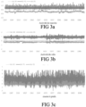
- FIG. 3a illustrates typical timing diagrams of the ⁇ x, ⁇ y and ⁇ z signals for a physical walking activity.
- FIG. 3b illustrates typical timing diagrams of the same ⁇ x, ⁇ y and ⁇ z signals for a physical cycling activity.
- FIG. 3c illustrates typical timing diagrams of ⁇ x, ⁇ y and ⁇ z signals for running physical activity.
- the profiles of these accelerations ⁇ x, ⁇ y and ⁇ z are very characteristic and are clearly distinguished according to the three physical activities considered: Walking; cycling or biking; running or jogging.
- the headlamp control module 100 is configured to come to execute a method of detecting a physical activity profile, detected within a set of N predetermined profiles.
- the control module 220 is configured so that the non-volatile memory 223 comprises a memory area in which data representative of several physical activity profiles are stored, and preferably the data representative of the activities " walking ", “ running “ and “ cycling “ . Furthermore, the non-volatile memory 223 also comprises an area intended for storing a micro-program allowing the processing of the accelerometer data ⁇ x, ⁇ y and ⁇ z generated on the fly by the 3D accelerometer module 110.
- This algorithm will, as will be detailed later in relation to the figure 5 , compare the ⁇ x, ⁇ y and ⁇ z data generated in real time with data stored in memory 223 which are characteristic of the predetermined profiles (walking, cycling, running) stored in the memory. The algorithm aims to bring together, at regular intervals, the accelerometer data of a determined profile so as to bring the signals generated by the accelerometer into the predefined physical activity category, i.e. that corresponding to the different profiles stored in the memory of the headlamp.
- FIG. 5 illustrates a method of light regulation in accordance with the present invention, based jointly on the detection of ambient brightness and the exploitation of accelerometer data.
- the method In a step 510, the method generates at regular intervals, for example every 20 milliseconds, a set of accelerometer data ⁇ x, ⁇ y and ⁇ z provided by the 3D accelerometer module 110.
- the method may be limited to only part of the accelerometer data, for example only the ⁇ y data along the vertical direction Y1.
- a step 520 the method stores the data ⁇ x, ⁇ y and ⁇ z in the RAM 222.
- the accelerometer data ⁇ x, ⁇ y and ⁇ z are subject to digital processing to select a physical activity profile from a set of N predetermined profiles stored in non-volatile memory 223.
- Several methods can be used to select or detect the physical activity profile and will be explained in more detail in section V of this description.
- a step 540 the method uses the profile selected in step 530 as an input pointer to access a look-up table (LUT) in which values and parameters specific to the dynamic or reactive regulation mechanism applied by the control module 220 of the headlamp 100 are stored, and allowing the generation of the information or the control signal 225 transmitted to the power module 210.
- LUT look-up table
- the parameters read from the LUT lookup table correspond to threshold values loaded into registers used by the reactive or dynamic regulation algorithm.
- the parameters are reduced to a threshold value corresponding to a minimum of lighting considered by the dynamic regulation algorithm.
- the dynamic regulation algorithm uses a set of separate registers in which threshold values corresponding to various brightnesses are stored, reading the look-up table provides these threshold values.
- the minimum brightness value but possibly also the maximum light power value, are defined based on the accelerometer data ⁇ x, ⁇ y and ⁇ z.
- the method reads the LUT table and extracts the parameter(s) stored therein and, in the case of the preferred embodiment which is particularly economical to implement, the method extracts the minimum threshold value which should be applied to the reactive or dynamic light regulation mechanism.
- a step 560 the reactive or dynamic light regulation mechanism is executed using the value(s) extracted from the LUT table so as to precisely adapt this regulation, and where appropriate the feedback loop fixing the light power generated by the headlamp to adapt it to the physical activity identified in step 530.
- the control information or the control signal transmitted via the conductor 225 is generated from the value(s) extracted from the LUT, together with the information provided by the light sensor 120.
- the dynamic or reactive regulation is therefore applied so as to ensure, in all cases, a minimum light power corresponding to the threshold value extracted from the LUT table.
- the LUT table may conveniently include, in addition to the minimum threshold value mentioned above, one or more additional parameters making it possible to set the beam geometry, and in particular the use of wide or narrow collimation, or even a combination of the two. It could even be advantageous to extract from the LUT table the proportions of distribution of the light power on the three beams: wide, mixed and pointed depending on the physical activity detected.
- step 570 the method loops to step 510 to perform the reading and processing of new accelerometer data ⁇ x, ⁇ y and ⁇ z.
- the reactive or dynamic light regulation mechanism is advantageously enriched by the contribution of the accelerometer data obtained on the fly from the accelerometer 110, and which the control module 220 processes to bring the processed data closer to a predetermined physical activity profile stored in the non-volatile memory 223 which, once identified, makes it possible to consult the LUT table so as to extract the most appropriate parameters and adjustment values for the light regulation.
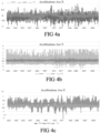
- FIG. 6 illustrates the effect of the process just described where we see that the low level threshold set without the input of accelerometer data remains at the same level regardless of the activity considered, for example walking (left part of the figure), running (middle part of the figure) and cycling or mountain biking (right part of the figure). If this low level does not pose any difficulty for a walking type activity, we observe on the other hand that this same low level presents a discomfort zone for a running activity and even becomes a danger zone for a mountain biking type activity.
- the process described in the figure 5 allows the low level threshold to be raised, to adapt it to a first higher level for a running activity and to raise it to a second even higher level for a mountain bike type activity, so that the user is never in the discomfort zone represented in the middle part of the figure 6 and even less in the danger zone of the right part of this same figure.
- the X1 and Y1 axes are placed in a sagittal plane relative to the user.
- Each elementary accelerometer is configured to provide a time series of elementary acceleration values along their corresponding axis.
- the first time series provided by the first elementary accelerometer, forms a first elementary raw signal, designated by S 1 b ( t, ⁇ ), which varies as a function of time t and of the motion profile ⁇ of the 3D acceleration sensor relative to the local terrestrial reference frame.
- the second time series provided by the second elementary accelerometer, forms a second elementary raw signal, designated by S 2 b ( t, ⁇ ), which varies as a function of time t and of the motion profile ⁇ of the 3D acceleration sensor relative to the local terrestrial reference frame.
- the third time series forms a third elementary raw signal, designated by S 3 b ( t , ⁇ ), which varies as a function of time t and of the motion profile ⁇ of the 3D acceleration sensor relative to the local terrestrial reference frame.
- the motion profile ⁇ of the 3D acceleration sensor is for example that of a walker, designated by ⁇ 1 , that of a cyclist, designated by ⁇ 2, or that of a runner, designated by ⁇ 3. As illustrated in particular in the Figures 8a to 8d .
- the control module 220 comprises a digital electronic circuit - which may advantageously be produced using the processor 221 associated with its memory or using any other specialized digital signal processor (DSP ), and which is configured to process only one or at least two of the raw signals S 1 b ( t , ⁇ ), S 2 b ( t , ⁇ ), S 3 b ( t, ⁇ ) provided by the 3D acceleration sensor according to a method 700 or algorithm for processing the signal and determining the movement profile of the 3D acceleration sensor illustrated in the figure. figure 7 , and finally allowing the detection of physical activity useful to the process of the figure 5 .
- DSP digital signal processor
- the 700 process of the figure 7 comprises an optional initial filtering step 710, followed by a feature extraction step 720, then a decision step 730 by thresholding.
- one or more of the raw signals S 1 b ( t , ⁇ ), S 2 b ( t , ⁇ ), S 3 b ( t , ⁇ ) are filtered respectively into new signals, called useful signals and referred to as S 1 u ( t , ⁇ ), S 2 u ( t , ⁇ ), S 3 u ( t , ⁇ ), in which the useful information is still present but where the harmful information, called “noise” (here electronic noise of the 3D acceleration sensor), is either removed or weakened.
- the overall information contained in the signal therefore has a certain degree of specialization at this level.
- the raw signals S 1 b ( t , ⁇ ) , S 2 b ( t , ⁇ ) , S 3 b ( t , ⁇ ) are respectively identical to the useful signals S 1 u ( t , ⁇ ), S 2 u ( t , ⁇ ), S 3 u ( t , ⁇ )
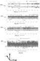
- the useful signals S 1 u ( t , ⁇ 0 ), S 2 u ( t , ⁇ 0 ) and S 3 u ( t , ⁇ 0 ), illustrated respectively on a first curve 802, a second curve 804, a third curve 806, are typically those of a 3D acceleration sensor having the shape 808 of a reference movement profile ⁇ 0 , corresponding to a low amplitude or quasi-zero movement of the 3D acceleration sensor.
- the useful signals S 1 u ( t, ⁇ 1), S 2 u ( t, ⁇ 1) and S 3 u ( t , ⁇ 1) illustrated respectively on a fourth curve 822, a fifth curve 824 and a sixth curve 826 are typically those of a 3D acceleration sensor having the shape 828 of a movement profile ⁇ 1 of a walker (in English “walking”).
- the useful signals S 1 u ( t , ⁇ 2 ), S 2 u ( t , ⁇ 2 ) and S 3 u ( t , ⁇ 2 ), illustrated respectively on a seventh curve 842, an eighth curve 844 and a ninth curve 846 are typically those of a 3D acceleration sensor having the shape 848 of a movement profile ⁇ 2 of a cyclist (in English “biking”).
- the useful signals S 1 u ( t, ⁇ 3), S 2 u ( t, ⁇ 3) and S 3 u ( t, ⁇ 3), illustrated respectively on a tenth curve 862, an eleventh curve 864 and a twelfth curve 866 are typically those of a 3D acceleration sensor having the shape 868 of a movement profile ⁇ 3 of a runner (in English “jogging”).
- the purpose of the feature extraction step 720 is to extract from at least one of the useful signals S 1 u ( t , ⁇ ), S 2 u ( t , ⁇ ), S 3 u ( t , ⁇ ) a finite set of one or more parameters, if possible independent, representative of the observed phenomenon, and making it possible to describe it.
- step 720 allows in other words the passage of a useful vector or scalar signal to data.
- a signal can be seen as a set of points for which each point has a high rate of dependence (deterministic or statistical) with its neighbors.
- Data represents a set of points where this notion of neighborhood is less important.
- the intermediate entities are then indifferently called signal, estimator, or data.
- the main goal of feature extraction is to arrive, from the useful signal, at data that are independent of each other and exhaustively represent the phenomenon to be interpreted.
- the useful signals studied here can be characterized by elementary estimators which are the moments of these signals: the mean (moment of order 1), and the pseudo-standard deviation (moment of order 2) are the best known and most used.
- an estimator can be a function of one or more moments of the same useful signal.
- Est(S2) is the statistical variance of the useful signal S 2 u ( t , ⁇ ).
- the type of lamp displacement profile is determined by thresholding on the estimator Est ( S 2 )( ⁇ ).
- the dimension of the problem of estimating the lamp displacement profile is considered equal to 3.
- the three elementary variables are formed by the respective statistical variances Est(S1)( ⁇ ), Est(S2)( ⁇ ), Est(S3)( ⁇ ), of the useful signals S 1 u ( t, ⁇ ), S 2 u ( t , ⁇ ), S 3 u ( t, ⁇ ).
- the type of lamp displacement profile is determined by thresholding on the scalar estimator Est ( S 1, S 2, S 3)( ⁇ ).
- the physical activity profile identified by the control module 220 is transmitted by the wireless link to the mobile telephone 300 so that the latter can inform, at any time, of the physical activity detected automatically according to the technique previously in order, if necessary, to allow the user to correct the detection and allow adaptive learning of the physical activity detection method.
- the headlamp is configured to read accelerometer data ⁇ x, ⁇ y and ⁇ z on the fly to determine the user's fall and, in this case, to trigger an emergency procedure.
- the procedure may be based on sending an alert signal to the mobile phone so as to initiate the generation of an emergency message, such as an SMS or email.
- the alert procedure will include activating the lamp to generate an alert light sequence, such as MORSE coding of the well-known S.O.S. sequence.
- Any other alert procedure may be considered once the headlamp control module 220 has detected the user's fall.
- the invention is not limited to headlamps only and can be used applied to a hand lamp.
Landscapes
- Engineering & Computer Science (AREA)
- General Engineering & Computer Science (AREA)
- Health & Medical Sciences (AREA)
- Physics & Mathematics (AREA)
- General Physics & Mathematics (AREA)
- Social Psychology (AREA)
- Business, Economics & Management (AREA)
- Emergency Management (AREA)
- Gerontology & Geriatric Medicine (AREA)
- General Health & Medical Sciences (AREA)
- Psychology (AREA)
- Psychiatry (AREA)
- Microelectronics & Electronic Packaging (AREA)
- Electromagnetism (AREA)
- Lighting Device Outwards From Vehicle And Optical Signal (AREA)
Claims (12)
- Ein Scheinwerfer (100) umfassend- eine Lichtquelle (231) mit einer oder mehreren Dioden vom Typ LED;- ein Leistungsmodul (230) zur Versorgung der Lichtquelle (231) mit Strom, wobei das Leistungsmodul durch eine Steuerinformation oder ein Steuersignal gesteuert wird;- ein Steuermodul (220) zur Einstellung der von der Lichtquelle erzeugten Lichtintensität;- einen Lichtsensor (120) zum Erfassen von Licht aus der Umgebung der Fassung des Scheinwerfers, wobei das Steuermodul (220) so konfiguriert ist, dass es die Steuerinformationen oder das Steuersignal entsprechend den von dem Lichtsensor (120) erzeugten informationen erzeugt,- einen Beschleunigungsmesser (110), der so konfiguriert ist, dass er in regelmäßigen Abständen Daten liefert, die für eine Beschleunigung des Scheinwerfers entlang mindestens einer horizontalen Achse und einer vertikalen Achse repräsentativ sind;wobei das Steuermodul (220) eine Schaltung (221, 222, 223) enthält, die so konfiguriert ist, dass sie Daten, die die Beschleunigung darstellen, digital speichert und verarbeitet;dadurch gekennzeichnet, dass- das Steuermodul (220) so konfiguriert ist, dass es ein körperliches Aktivitätsprofil aus einem Satz vorbestimmter körperlicher Aktivitäten, die in einem Speicher (223) gespeichert sind, aus Daten auswählt, die die digital verarbeitete Beschleunigung darstellen; undwobei das Steuermodul (220) eine in dem Speicher (223) gespeicherte LUT-Nachschlagetabelle umfasst, die mindestens einen Wert oder Einstellparameter bereitstellt, der zur Erzeugung der Steuerinformation oder des Steuersignals dient;wobei das körperliche Aktivitätsprofil als Eingangszeiger in der Nachschlagetabelle LUT dient;wobei der aus der Nachschlagetabelle LUT ausgelesene Wert oder Einstellparameter in Verbindung mit der vom Lichtsensor erzeugten Information verwendet wird, um die Steuerinformation oder das Steuersignal zu bestimmen.
- Scheinwerfer nach Anspruch 1, wobei der Beschleunigungsmesser (110) so konfiguriert ist, dass er Beschleunigungsmessdaten entlang zweier horizontaler Achsen X1, Z1 und entlang einer vertikalen Achse Y1 erzeugt; und
wobei der Satz von vorbestimmten Beschleunigungsmessungsprofilen Profile enthält, die für Gehen, Laufen und Radfahren repräsentativ sind. - Scheinwerfer nach Anspruch 1, bei dem die von der Steuereinheit (220) eingestellte Leistung des Lichtstrahls zwischen zwei Schwellenwerten, nämlich einem niedrigen und einem hohen Schwellenwert, variiert, wobei der niedrige Schwellenwert durch einen direkt aus der Nachschlagetabelle LUT entnommenen Wert eingestellt wird.
- Scheinwerfer nach Anspruch 1, bei dem die Schaltung (221, 222, 223), die so konfiguriert ist, dass sie die für die Beschleunigung repräsentativen Daten speichert und verarbeitet, ein digitales und statistisches Verarbeitungsverfahren verwendet, das auf der Messung der Varianz der Komponente der vertikalen Beschleunigung µy1 des Scheinwerfers beruht.
- Scheinwerfer nach Anspruch 4, bei dem die Schaltung (221, 222, 223), die so konfiguriert ist, dass sie die für die Beschleunigung repräsentativen Daten speichert und verarbeitet, ein digitales und statistisches Verarbeitungsverfahren verwendet, das auf der Messung der Varianz von zwei Komponenten der Beschleunigung des Scheinwerfers beruht.
- Scheinwerfer nach Anspruch 1, dadurch gekennzeichnet, dass die aus der LUT-Tabelle extrahierten Daten es ermöglichen, einen Schwellenwert für die Mindestlichtleistung und eine spezifische Geometrie des Lichtbündels zu definieren, die zwischen einem breiten Lichtbündel, einem engen fokussierenden Lichtbündel und/oder beiden gleichzeitig gewählt wird.
- Scheinwerfer nach Anspruch 1, wobei das Steuermodul (220) so konfiguriert ist, dass es Daten vom Beschleunigungsmesser verarbeitet, um den Sturz eines Benutzers zu erkennen.
- Scheinwerfer nach Anspruch 7, wobei das Steuermodul die Information über den Sturz des Benutzers übermittelt, um einen elektronischen Alarm zu erzeugen, der an ein Mobiltelefon übertragen wird.
- Scheinwerfer nach Anspruch 7, wobei das Steuermodul so konfiguriert ist, dass es eine Lichtwarnsequenz steuert, die darauf abzielt, um Hilfe zu rufen.
- Verfahren zur Lichtregelung eines Scheinwerfers nach einem der vorhergehenden Ansprüche, umfassend die Schritte:- Erzeugen (510) eines Satzes von Beschleunigungsmesserdaten µx1, µy1 und µz1 in regelmäßigen Abständen entsprechend einer ersten vorbestimmten horizontalen Achse X1, einer vorbestimmten vertikalen Achse Y1 und einer zweiten vorbestimmten horizontalen Achse Z1, die von dem Beschleunigungsmesser geliefert werden;- Speichern (520) der Daten µx1, µy1 und µz1 in einem Direktzugriffsspeicher (222);- Durchführen einer digitalen Verarbeitung (530) der Beschleunigungsmesserdaten µx1, µy1 und µz1, um ein körperliches Aktivitätsprofil zu bestimmen, das aus einem Satz von N vorbestimmten Profilen ausgewählt wird, die in einem nichtflüchtigen Speicher (223) gespeichert sind;- Verwenden (540) des ausgewählten Profils als Eingangszeiger für den Zugriff auf eine Nachschlagetabelle LUT, in der Werte und Parameter gespeichert sind, die für den Mechanismus spezifisch sind, der die Erzeugung der genannten Steuerinformation oder des genannten Steuersignals zur Einstellung der Lichtleistung ermöglicht;- Lesen der Nachschlagetabelle LUT (550) und Extrahieren des/der darin gespeicherten Parameters/Parameter oder Werte;- Bestimmen der Steuerinformation oder des Steuersignals aus dem Wert oder den Werten, die aus der Nachschlagetabelle LUT extrahiert wurden, zusammen mit der von dem Lichtsensor (120) gelieferten Information;- zum ersten Schritt zurückkehren, um neue Beschleunigungsmesserdaten zu lesen und zu verarbeiten.
- Verfahren nach Anspruch 10, wobei das Auslesen der Nachschlagetabelle LUT einen Wert liefert, der die von der Lampe erzeugte Mindestleistung definiert.
- Scheinwerfer nach Anspruch 1, bei dem die aus der Nachschlagetabelle LUT extrahierten Daten die Definition eines Mindestschwellenwerts der Lichtleistung und die Einstellung einer spezifischen Geometrie des Lichtstrahls durch die Auswahl eines Betriebsmodus über das Steuermodul (220) ermöglichen, der aus einem ersten Modus mit breitem Lichtstrahl, einem zweiten Modus mit schmalem Lichtstrahl und einem dritten Modus mit gleichzeitig breitem und schmalem Lichtstrahl ausgewählt wird.
Priority Applications (4)
| Application Number | Priority Date | Filing Date | Title |
|---|---|---|---|
| EP21164886.0A EP4064792B1 (de) | 2021-03-25 | 2021-03-25 | Stirnlampe, die mit einer verbesserten dynamischen beleuchtung ausgestattet ist |
| TW111108423A TWI918880B (zh) | 2021-03-25 | 2022-03-08 | 燈及其光調節方法 |
| US17/703,478 US11519591B2 (en) | 2021-03-25 | 2022-03-24 | Headlamp comprising improved dynamic lighting |
| CN202210306213.1A CN115134975A (zh) | 2021-03-25 | 2022-03-25 | 包括改进的动态照明的头灯 |
Applications Claiming Priority (1)
| Application Number | Priority Date | Filing Date | Title |
|---|---|---|---|
| EP21164886.0A EP4064792B1 (de) | 2021-03-25 | 2021-03-25 | Stirnlampe, die mit einer verbesserten dynamischen beleuchtung ausgestattet ist |
Publications (2)
| Publication Number | Publication Date |
|---|---|
| EP4064792A1 EP4064792A1 (de) | 2022-09-28 |
| EP4064792B1 true EP4064792B1 (de) | 2024-09-04 |
Family
ID=75223170
Family Applications (1)
| Application Number | Title | Priority Date | Filing Date |
|---|---|---|---|
| EP21164886.0A Active EP4064792B1 (de) | 2021-03-25 | 2021-03-25 | Stirnlampe, die mit einer verbesserten dynamischen beleuchtung ausgestattet ist |
Country Status (3)
| Country | Link |
|---|---|
| US (1) | US11519591B2 (de) |
| EP (1) | EP4064792B1 (de) |
| CN (1) | CN115134975A (de) |
Families Citing this family (2)
| Publication number | Priority date | Publication date | Assignee | Title |
|---|---|---|---|---|
| FR3143714B1 (fr) * | 2022-12-16 | 2025-03-14 | Golum | Module d’éclairage pour lampe frontale optimisé pour la pratique du vélo |
| EP4657991A1 (de) | 2024-05-29 | 2025-12-03 | Zedel | Frontleuchte mit verbesserter benutzerschnittstelle |
Family Cites Families (9)
| Publication number | Priority date | Publication date | Assignee | Title |
|---|---|---|---|---|
| EP2701801A2 (de) * | 2011-04-28 | 2014-03-05 | Lighten Aps | Beleuchtungssystem und verfahren zur lokalen änderung der lichtbedingungen |
| US9125015B2 (en) * | 2013-06-28 | 2015-09-01 | Facebook, Inc. | User activity tracking system and device |
| FR3017691B1 (fr) * | 2014-02-14 | 2019-06-28 | Zedel | Lampe electrique portative dotee d'un systeme de communication sans-fil |
| FR3017692A1 (fr) * | 2014-02-14 | 2015-08-21 | Zedel | Lampe portative comportant un dispositif de commande electrique de la geometrie du faisceau electrique |
| CN105120560B (zh) * | 2015-08-26 | 2017-10-10 | 李文杰 | 基于加速度传感器与光线传感器自适应自行车灯 |
| FR3041498A1 (fr) * | 2015-09-21 | 2017-03-24 | Zedel | Lampe led dotee d'un dispositif de regulation de la luminosite |
| TW201740771A (zh) * | 2016-05-04 | 2017-11-16 | Idea Pond Llc | 自動感應手電筒控制組件 |
| CN108377593A (zh) * | 2018-03-01 | 2018-08-07 | 广东欧珀移动通信有限公司 | 控制照明方法、装置、系统、耳机及计算机可读存储介质 |
| EP3654346A1 (de) * | 2018-11-16 | 2020-05-20 | Koninklijke Philips N.V. | Bestimmen einer transformationsmatrix |
-
2021
- 2021-03-25 EP EP21164886.0A patent/EP4064792B1/de active Active
-
2022
- 2022-03-24 US US17/703,478 patent/US11519591B2/en active Active
- 2022-03-25 CN CN202210306213.1A patent/CN115134975A/zh active Pending
Also Published As
| Publication number | Publication date |
|---|---|
| US20220307678A1 (en) | 2022-09-29 |
| TW202240099A (zh) | 2022-10-16 |
| CN115134975A (zh) | 2022-09-30 |
| US11519591B2 (en) | 2022-12-06 |
| EP4064792A1 (de) | 2022-09-28 |
Similar Documents
| Publication | Publication Date | Title |
|---|---|---|
| EP2684426B1 (de) | Led-lampe mit einer strahlvorrichtung mit veränderlicher geometrie | |
| EP3463051B1 (de) | Verbundene vorrichtung zur verhaltensüberwachung eines individuums und zur detektion und/oder verhinderung einer anomalie | |
| EP2706823B1 (de) | Tragbare elektrische lampe, die mit einer vorrichtung zur automatischen beleuchtungsregulierung ausgestattet ist | |
| EP4064792B1 (de) | Stirnlampe, die mit einer verbesserten dynamischen beleuchtung ausgestattet ist | |
| EP3145280B1 (de) | Led-lampe mit regulierungsvorrichtung der leuchtkraft | |
| EP2706824A1 (de) | Tragbare elektrische Lampe, die mit einem Blendschutzsystem ausgestattet ist | |
| US11595585B2 (en) | Exposure change control in low light environments | |
| EP3387794B1 (de) | Verfahren und system zur wiedergewinnung von betriebsdaten einer vorrichtung zur messung von hirnwellen | |
| WO2017093439A1 (fr) | Dispositif de commande vocale d'un appareil de capture d'images | |
| EP3228026B1 (de) | Elektronische vorrichtung im zusammenhang mit einem photovoltaischen modul zur optimierung des durchsatzes einer bidirektionalen vlc-übertragung | |
| EP3776069B1 (de) | Optisches system zur detektion und verfolgung von augenbewegungen, zugehöriger externer rahmen und zugehörige verbundene kontaktlinse | |
| EP4411666A1 (de) | System zur erfassung eines farbbildes und eines infrarotbildes einer szene | |
| EP2942884B1 (de) | Optimierung des durchsatzes in einem li-fi-system | |
| EP3330891A2 (de) | Kommunikationssystem mit betrugsbekämpfungsvorrichtung | |
| EP4657991A1 (de) | Frontleuchte mit verbesserter benutzerschnittstelle | |
| EP1538557A2 (de) | Widerstands- und Kapazitätsmodulation in einem elektromagnetischen Transponder | |
| EP3364565A1 (de) | Kommunikationsverfahren über sichtbares licht | |
| TWI918880B (zh) | 燈及其光調節方法 | |
| EP1672858A2 (de) | Fehlerdetektion in einem amplituden modulierten Signal | |
| FR3088458A1 (fr) | Procede de reconnaissance et de description contextuelles d'un objet d'interet pour un utilisateur deficient visuel, dispositif mettant en oeuvre ledit procede | |
| WO2025119680A1 (en) | Wireless optical communication interface for personal care device and accessory device | |
| FR3074383B1 (fr) | Procede de reception d’un signal lumineux module de type signal vlc | |
| FR3066667A1 (fr) | " procede et systeme de transmission serie de donnees " | |
| FR3102284A1 (fr) | Procédé d’ouverture d’une partie d’un véhicule automobile | |
| FR2700033A1 (fr) | Procédé de transfert à distance et sans fil de données, d'un module d'acquisition de données à un poste de stockage de données et dispositif pour la mise en Óoeuvre de ce procédé. |
Legal Events
| Date | Code | Title | Description |
|---|---|---|---|
| PUAI | Public reference made under article 153(3) epc to a published international application that has entered the european phase |
Free format text: ORIGINAL CODE: 0009012 |
|
| STAA | Information on the status of an ep patent application or granted ep patent |
Free format text: STATUS: THE APPLICATION HAS BEEN PUBLISHED |
|
| AK | Designated contracting states |
Kind code of ref document: A1 Designated state(s): AL AT BE BG CH CY CZ DE DK EE ES FI FR GB GR HR HU IE IS IT LI LT LU LV MC MK MT NL NO PL PT RO RS SE SI SK SM TR |
|
| STAA | Information on the status of an ep patent application or granted ep patent |
Free format text: STATUS: REQUEST FOR EXAMINATION WAS MADE |
|
| 17P | Request for examination filed |
Effective date: 20230326 |
|
| RBV | Designated contracting states (corrected) |
Designated state(s): AL AT BE BG CH CY CZ DE DK EE ES FI FR GB GR HR HU IE IS IT LI LT LU LV MC MK MT NL NO PL PT RO RS SE SI SK SM TR |
|
| GRAP | Despatch of communication of intention to grant a patent |
Free format text: ORIGINAL CODE: EPIDOSNIGR1 |
|
| STAA | Information on the status of an ep patent application or granted ep patent |
Free format text: STATUS: GRANT OF PATENT IS INTENDED |
|
| INTG | Intention to grant announced |
Effective date: 20240321 |
|
| RIC1 | Information provided on ipc code assigned before grant |
Ipc: F21V 23/04 20060101ALI20240308BHEP Ipc: H05B 47/11 20200101ALI20240308BHEP Ipc: H05B 47/115 20200101ALI20240308BHEP Ipc: F21L 4/00 20060101ALI20240308BHEP Ipc: H05B 47/17 20200101ALI20240308BHEP Ipc: H05B 45/10 20200101AFI20240308BHEP |
|
| GRAS | Grant fee paid |
Free format text: ORIGINAL CODE: EPIDOSNIGR3 |
|
| GRAA | (expected) grant |
Free format text: ORIGINAL CODE: 0009210 |
|
| STAA | Information on the status of an ep patent application or granted ep patent |
Free format text: STATUS: THE PATENT HAS BEEN GRANTED |
|
| AK | Designated contracting states |
Kind code of ref document: B1 Designated state(s): AL AT BE BG CH CY CZ DE DK EE ES FI FR GB GR HR HU IE IS IT LI LT LU LV MC MK MT NL NO PL PT RO RS SE SI SK SM TR |
|
| REG | Reference to a national code |
Ref country code: GB Ref legal event code: FG4D Free format text: NOT ENGLISH |
|
| REG | Reference to a national code |
Ref country code: CH Ref legal event code: EP |
|
| REG | Reference to a national code |
Ref country code: IE Ref legal event code: FG4D Free format text: LANGUAGE OF EP DOCUMENT: FRENCH |
|
| REG | Reference to a national code |
Ref country code: DE Ref legal event code: R096 Ref document number: 602021018136 Country of ref document: DE |
|
| REG | Reference to a national code |
Ref country code: SE Ref legal event code: TRGR |
|
| REG | Reference to a national code |
Ref country code: LT Ref legal event code: MG9D |
|
| REG | Reference to a national code |
Ref country code: NL Ref legal event code: MP Effective date: 20240904 |
|
| PG25 | Lapsed in a contracting state [announced via postgrant information from national office to epo] |
Ref country code: NO Free format text: LAPSE BECAUSE OF FAILURE TO SUBMIT A TRANSLATION OF THE DESCRIPTION OR TO PAY THE FEE WITHIN THE PRESCRIBED TIME-LIMIT Effective date: 20241204 |
|
| PG25 | Lapsed in a contracting state [announced via postgrant information from national office to epo] |
Ref country code: PL Free format text: LAPSE BECAUSE OF FAILURE TO SUBMIT A TRANSLATION OF THE DESCRIPTION OR TO PAY THE FEE WITHIN THE PRESCRIBED TIME-LIMIT Effective date: 20240904 Ref country code: GR Free format text: LAPSE BECAUSE OF FAILURE TO SUBMIT A TRANSLATION OF THE DESCRIPTION OR TO PAY THE FEE WITHIN THE PRESCRIBED TIME-LIMIT Effective date: 20241205 Ref country code: FI Free format text: LAPSE BECAUSE OF FAILURE TO SUBMIT A TRANSLATION OF THE DESCRIPTION OR TO PAY THE FEE WITHIN THE PRESCRIBED TIME-LIMIT Effective date: 20240904 |
|
| PG25 | Lapsed in a contracting state [announced via postgrant information from national office to epo] |
Ref country code: BG Free format text: LAPSE BECAUSE OF FAILURE TO SUBMIT A TRANSLATION OF THE DESCRIPTION OR TO PAY THE FEE WITHIN THE PRESCRIBED TIME-LIMIT Effective date: 20240904 |
|
| PG25 | Lapsed in a contracting state [announced via postgrant information from national office to epo] |
Ref country code: LV Free format text: LAPSE BECAUSE OF FAILURE TO SUBMIT A TRANSLATION OF THE DESCRIPTION OR TO PAY THE FEE WITHIN THE PRESCRIBED TIME-LIMIT Effective date: 20240904 |
|
| PG25 | Lapsed in a contracting state [announced via postgrant information from national office to epo] |
Ref country code: HR Free format text: LAPSE BECAUSE OF FAILURE TO SUBMIT A TRANSLATION OF THE DESCRIPTION OR TO PAY THE FEE WITHIN THE PRESCRIBED TIME-LIMIT Effective date: 20240904 |
|
| PG25 | Lapsed in a contracting state [announced via postgrant information from national office to epo] |
Ref country code: ES Free format text: LAPSE BECAUSE OF FAILURE TO SUBMIT A TRANSLATION OF THE DESCRIPTION OR TO PAY THE FEE WITHIN THE PRESCRIBED TIME-LIMIT Effective date: 20240904 Ref country code: RS Free format text: LAPSE BECAUSE OF FAILURE TO SUBMIT A TRANSLATION OF THE DESCRIPTION OR TO PAY THE FEE WITHIN THE PRESCRIBED TIME-LIMIT Effective date: 20241204 |
|
| PG25 | Lapsed in a contracting state [announced via postgrant information from national office to epo] |
Ref country code: RS Free format text: LAPSE BECAUSE OF FAILURE TO SUBMIT A TRANSLATION OF THE DESCRIPTION OR TO PAY THE FEE WITHIN THE PRESCRIBED TIME-LIMIT Effective date: 20241204 Ref country code: PL Free format text: LAPSE BECAUSE OF FAILURE TO SUBMIT A TRANSLATION OF THE DESCRIPTION OR TO PAY THE FEE WITHIN THE PRESCRIBED TIME-LIMIT Effective date: 20240904 Ref country code: NO Free format text: LAPSE BECAUSE OF FAILURE TO SUBMIT A TRANSLATION OF THE DESCRIPTION OR TO PAY THE FEE WITHIN THE PRESCRIBED TIME-LIMIT Effective date: 20241204 Ref country code: LV Free format text: LAPSE BECAUSE OF FAILURE TO SUBMIT A TRANSLATION OF THE DESCRIPTION OR TO PAY THE FEE WITHIN THE PRESCRIBED TIME-LIMIT Effective date: 20240904 Ref country code: HR Free format text: LAPSE BECAUSE OF FAILURE TO SUBMIT A TRANSLATION OF THE DESCRIPTION OR TO PAY THE FEE WITHIN THE PRESCRIBED TIME-LIMIT Effective date: 20240904 Ref country code: GR Free format text: LAPSE BECAUSE OF FAILURE TO SUBMIT A TRANSLATION OF THE DESCRIPTION OR TO PAY THE FEE WITHIN THE PRESCRIBED TIME-LIMIT Effective date: 20241205 Ref country code: FI Free format text: LAPSE BECAUSE OF FAILURE TO SUBMIT A TRANSLATION OF THE DESCRIPTION OR TO PAY THE FEE WITHIN THE PRESCRIBED TIME-LIMIT Effective date: 20240904 Ref country code: ES Free format text: LAPSE BECAUSE OF FAILURE TO SUBMIT A TRANSLATION OF THE DESCRIPTION OR TO PAY THE FEE WITHIN THE PRESCRIBED TIME-LIMIT Effective date: 20240904 Ref country code: BG Free format text: LAPSE BECAUSE OF FAILURE TO SUBMIT A TRANSLATION OF THE DESCRIPTION OR TO PAY THE FEE WITHIN THE PRESCRIBED TIME-LIMIT Effective date: 20240904 |
|
| REG | Reference to a national code |
Ref country code: AT Ref legal event code: MK05 Ref document number: 1721757 Country of ref document: AT Kind code of ref document: T Effective date: 20240904 |
|
| PG25 | Lapsed in a contracting state [announced via postgrant information from national office to epo] |
Ref country code: NL Free format text: LAPSE BECAUSE OF FAILURE TO SUBMIT A TRANSLATION OF THE DESCRIPTION OR TO PAY THE FEE WITHIN THE PRESCRIBED TIME-LIMIT Effective date: 20240904 |
|
| PGFP | Annual fee paid to national office [announced via postgrant information from national office to epo] |
Ref country code: SE Payment date: 20250311 Year of fee payment: 5 |
|
| PG25 | Lapsed in a contracting state [announced via postgrant information from national office to epo] |
Ref country code: PT Free format text: LAPSE BECAUSE OF FAILURE TO SUBMIT A TRANSLATION OF THE DESCRIPTION OR TO PAY THE FEE WITHIN THE PRESCRIBED TIME-LIMIT Effective date: 20250106 Ref country code: IS Free format text: LAPSE BECAUSE OF FAILURE TO SUBMIT A TRANSLATION OF THE DESCRIPTION OR TO PAY THE FEE WITHIN THE PRESCRIBED TIME-LIMIT Effective date: 20250104 |
|
| PGFP | Annual fee paid to national office [announced via postgrant information from national office to epo] |
Ref country code: DE Payment date: 20250319 Year of fee payment: 5 |
|
| PG25 | Lapsed in a contracting state [announced via postgrant information from national office to epo] |
Ref country code: SM Free format text: LAPSE BECAUSE OF FAILURE TO SUBMIT A TRANSLATION OF THE DESCRIPTION OR TO PAY THE FEE WITHIN THE PRESCRIBED TIME-LIMIT Effective date: 20240904 Ref country code: RO Free format text: LAPSE BECAUSE OF FAILURE TO SUBMIT A TRANSLATION OF THE DESCRIPTION OR TO PAY THE FEE WITHIN THE PRESCRIBED TIME-LIMIT Effective date: 20240904 |
|
| PG25 | Lapsed in a contracting state [announced via postgrant information from national office to epo] |
Ref country code: EE Free format text: LAPSE BECAUSE OF FAILURE TO SUBMIT A TRANSLATION OF THE DESCRIPTION OR TO PAY THE FEE WITHIN THE PRESCRIBED TIME-LIMIT Effective date: 20240904 Ref country code: AT Free format text: LAPSE BECAUSE OF FAILURE TO SUBMIT A TRANSLATION OF THE DESCRIPTION OR TO PAY THE FEE WITHIN THE PRESCRIBED TIME-LIMIT Effective date: 20240904 |
|
| PG25 | Lapsed in a contracting state [announced via postgrant information from national office to epo] |
Ref country code: CZ Free format text: LAPSE BECAUSE OF FAILURE TO SUBMIT A TRANSLATION OF THE DESCRIPTION OR TO PAY THE FEE WITHIN THE PRESCRIBED TIME-LIMIT Effective date: 20240904 |
|
| PGFP | Annual fee paid to national office [announced via postgrant information from national office to epo] |
Ref country code: FR Payment date: 20250324 Year of fee payment: 5 |
|
| PG25 | Lapsed in a contracting state [announced via postgrant information from national office to epo] |
Ref country code: SK Free format text: LAPSE BECAUSE OF FAILURE TO SUBMIT A TRANSLATION OF THE DESCRIPTION OR TO PAY THE FEE WITHIN THE PRESCRIBED TIME-LIMIT Effective date: 20240904 Ref country code: IT Free format text: LAPSE BECAUSE OF FAILURE TO SUBMIT A TRANSLATION OF THE DESCRIPTION OR TO PAY THE FEE WITHIN THE PRESCRIBED TIME-LIMIT Effective date: 20240904 |
|
| PGFP | Annual fee paid to national office [announced via postgrant information from national office to epo] |
Ref country code: GB Payment date: 20250324 Year of fee payment: 5 |
|
| REG | Reference to a national code |
Ref country code: DE Ref legal event code: R097 Ref document number: 602021018136 Country of ref document: DE |
|
| PG25 | Lapsed in a contracting state [announced via postgrant information from national office to epo] |
Ref country code: DK Free format text: LAPSE BECAUSE OF FAILURE TO SUBMIT A TRANSLATION OF THE DESCRIPTION OR TO PAY THE FEE WITHIN THE PRESCRIBED TIME-LIMIT Effective date: 20240904 |
|
| PLBE | No opposition filed within time limit |
Free format text: ORIGINAL CODE: 0009261 |
|
| STAA | Information on the status of an ep patent application or granted ep patent |
Free format text: STATUS: NO OPPOSITION FILED WITHIN TIME LIMIT |
|
| 26N | No opposition filed |
Effective date: 20250605 |
|
| PG25 | Lapsed in a contracting state [announced via postgrant information from national office to epo] |
Ref country code: MC Free format text: LAPSE BECAUSE OF FAILURE TO SUBMIT A TRANSLATION OF THE DESCRIPTION OR TO PAY THE FEE WITHIN THE PRESCRIBED TIME-LIMIT Effective date: 20240904 |
|
| REG | Reference to a national code |
Ref country code: CH Ref legal event code: H13 Free format text: ST27 STATUS EVENT CODE: U-0-0-H10-H13 (AS PROVIDED BY THE NATIONAL OFFICE) Effective date: 20251024 |
|
| PG25 | Lapsed in a contracting state [announced via postgrant information from national office to epo] |
Ref country code: LU Free format text: LAPSE BECAUSE OF NON-PAYMENT OF DUE FEES Effective date: 20250325 |
|
| REG | Reference to a national code |
Ref country code: BE Ref legal event code: MM Effective date: 20250331 |
|
| PG25 | Lapsed in a contracting state [announced via postgrant information from national office to epo] |
Ref country code: BE Free format text: LAPSE BECAUSE OF NON-PAYMENT OF DUE FEES Effective date: 20250331 |
|
| PG25 | Lapsed in a contracting state [announced via postgrant information from national office to epo] |
Ref country code: CH Free format text: LAPSE BECAUSE OF NON-PAYMENT OF DUE FEES Effective date: 20250331 |
|
| PG25 | Lapsed in a contracting state [announced via postgrant information from national office to epo] |
Ref country code: IE Free format text: LAPSE BECAUSE OF NON-PAYMENT OF DUE FEES Effective date: 20250325 |