EP4064708B1 - Bildcodierungsvorrichtung und verfahren zum steuern von schleifenfilterung - Google Patents
Bildcodierungsvorrichtung und verfahren zum steuern von schleifenfilterung Download PDFInfo
- Publication number
- EP4064708B1 EP4064708B1 EP20891070.3A EP20891070A EP4064708B1 EP 4064708 B1 EP4064708 B1 EP 4064708B1 EP 20891070 A EP20891070 A EP 20891070A EP 4064708 B1 EP4064708 B1 EP 4064708B1
- Authority
- EP
- European Patent Office
- Prior art keywords
- virtual
- boundaries
- sps
- information
- flag
- Prior art date
- Legal status (The legal status is an assumption and is not a legal conclusion. Google has not performed a legal analysis and makes no representation as to the accuracy of the status listed.)
- Active
Links
Images


Classifications
-
- H—ELECTRICITY
- H04—ELECTRIC COMMUNICATION TECHNIQUE
- H04N—PICTORIAL COMMUNICATION, e.g. TELEVISION
- H04N19/00—Methods or arrangements for coding, decoding, compressing or decompressing digital video signals
- H04N19/80—Details of filtering operations specially adapted for video compression, e.g. for pixel interpolation
- H04N19/82—Details of filtering operations specially adapted for video compression, e.g. for pixel interpolation involving filtering within a prediction loop
-
- H—ELECTRICITY
- H04—ELECTRIC COMMUNICATION TECHNIQUE
- H04N—PICTORIAL COMMUNICATION, e.g. TELEVISION
- H04N19/00—Methods or arrangements for coding, decoding, compressing or decompressing digital video signals
- H04N19/10—Methods or arrangements for coding, decoding, compressing or decompressing digital video signals using adaptive coding
- H04N19/102—Methods or arrangements for coding, decoding, compressing or decompressing digital video signals using adaptive coding characterised by the element, parameter or selection affected or controlled by the adaptive coding
- H04N19/103—Selection of coding mode or of prediction mode
-
- H—ELECTRICITY
- H04—ELECTRIC COMMUNICATION TECHNIQUE
- H04N—PICTORIAL COMMUNICATION, e.g. TELEVISION
- H04N19/00—Methods or arrangements for coding, decoding, compressing or decompressing digital video signals
- H04N19/10—Methods or arrangements for coding, decoding, compressing or decompressing digital video signals using adaptive coding
- H04N19/102—Methods or arrangements for coding, decoding, compressing or decompressing digital video signals using adaptive coding characterised by the element, parameter or selection affected or controlled by the adaptive coding
- H04N19/117—Filters, e.g. for pre-processing or post-processing
-
- H—ELECTRICITY
- H04—ELECTRIC COMMUNICATION TECHNIQUE
- H04N—PICTORIAL COMMUNICATION, e.g. TELEVISION
- H04N19/00—Methods or arrangements for coding, decoding, compressing or decompressing digital video signals
- H04N19/10—Methods or arrangements for coding, decoding, compressing or decompressing digital video signals using adaptive coding
- H04N19/102—Methods or arrangements for coding, decoding, compressing or decompressing digital video signals using adaptive coding characterised by the element, parameter or selection affected or controlled by the adaptive coding
- H04N19/132—Sampling, masking or truncation of coding units, e.g. adaptive resampling, frame skipping, frame interpolation or high-frequency transform coefficient masking
-
- H—ELECTRICITY
- H04—ELECTRIC COMMUNICATION TECHNIQUE
- H04N—PICTORIAL COMMUNICATION, e.g. TELEVISION
- H04N19/00—Methods or arrangements for coding, decoding, compressing or decompressing digital video signals
- H04N19/10—Methods or arrangements for coding, decoding, compressing or decompressing digital video signals using adaptive coding
- H04N19/134—Methods or arrangements for coding, decoding, compressing or decompressing digital video signals using adaptive coding characterised by the element, parameter or criterion affecting or controlling the adaptive coding
- H04N19/136—Incoming video signal characteristics or properties
- H04N19/14—Coding unit complexity, e.g. amount of activity or edge presence estimation
-
- H—ELECTRICITY
- H04—ELECTRIC COMMUNICATION TECHNIQUE
- H04N—PICTORIAL COMMUNICATION, e.g. TELEVISION
- H04N19/00—Methods or arrangements for coding, decoding, compressing or decompressing digital video signals
- H04N19/10—Methods or arrangements for coding, decoding, compressing or decompressing digital video signals using adaptive coding
- H04N19/134—Methods or arrangements for coding, decoding, compressing or decompressing digital video signals using adaptive coding characterised by the element, parameter or criterion affecting or controlling the adaptive coding
- H04N19/167—Position within a video image, e.g. region of interest [ROI]
-
- H—ELECTRICITY
- H04—ELECTRIC COMMUNICATION TECHNIQUE
- H04N—PICTORIAL COMMUNICATION, e.g. TELEVISION
- H04N19/00—Methods or arrangements for coding, decoding, compressing or decompressing digital video signals
- H04N19/10—Methods or arrangements for coding, decoding, compressing or decompressing digital video signals using adaptive coding
- H04N19/169—Methods or arrangements for coding, decoding, compressing or decompressing digital video signals using adaptive coding characterised by the coding unit, i.e. the structural portion or semantic portion of the video signal being the object or the subject of the adaptive coding
- H04N19/17—Methods or arrangements for coding, decoding, compressing or decompressing digital video signals using adaptive coding characterised by the coding unit, i.e. the structural portion or semantic portion of the video signal being the object or the subject of the adaptive coding the unit being an image region, e.g. an object
- H04N19/172—Methods or arrangements for coding, decoding, compressing or decompressing digital video signals using adaptive coding characterised by the coding unit, i.e. the structural portion or semantic portion of the video signal being the object or the subject of the adaptive coding the unit being an image region, e.g. an object the region being a picture, frame or field
-
- H—ELECTRICITY
- H04—ELECTRIC COMMUNICATION TECHNIQUE
- H04N—PICTORIAL COMMUNICATION, e.g. TELEVISION
- H04N19/00—Methods or arrangements for coding, decoding, compressing or decompressing digital video signals
- H04N19/10—Methods or arrangements for coding, decoding, compressing or decompressing digital video signals using adaptive coding
- H04N19/169—Methods or arrangements for coding, decoding, compressing or decompressing digital video signals using adaptive coding characterised by the coding unit, i.e. the structural portion or semantic portion of the video signal being the object or the subject of the adaptive coding
- H04N19/17—Methods or arrangements for coding, decoding, compressing or decompressing digital video signals using adaptive coding characterised by the coding unit, i.e. the structural portion or semantic portion of the video signal being the object or the subject of the adaptive coding the unit being an image region, e.g. an object
- H04N19/176—Methods or arrangements for coding, decoding, compressing or decompressing digital video signals using adaptive coding characterised by the coding unit, i.e. the structural portion or semantic portion of the video signal being the object or the subject of the adaptive coding the unit being an image region, e.g. an object the region being a block, e.g. a macroblock
-
- H—ELECTRICITY
- H04—ELECTRIC COMMUNICATION TECHNIQUE
- H04N—PICTORIAL COMMUNICATION, e.g. TELEVISION
- H04N19/00—Methods or arrangements for coding, decoding, compressing or decompressing digital video signals
- H04N19/70—Methods or arrangements for coding, decoding, compressing or decompressing digital video signals characterised by syntax aspects related to video coding, e.g. related to compression standards
Definitions
- the present disclosure relates to an image coding apparatus and method for controlling loop filtering.
- VR virtual reality
- AR artificial reality
- holograms broadcasting for image/video is having characteristics different from reality images such as game images has increased.
- a highly efficient image/video compression technology is required to effectively compress, transmit, store, and reproduce information of a high-resolution, high-quality image/video having various characteristics as described above.
- an image decoding method is provided as set out in claim 1
- an image encoding method is provided as set out in claim 2
- a computer readable storage medium storing a bitstream is provided as set out in claim 3
- a transmission method of data for an image is provided as set out in claim 4.
- each configuration of the drawings described in this document is an independent illustration for explaining functions as features that are different from each other, and does not mean that each configuration is implemented by mutually different hardware or different software.
- two or more of the configurations can be combined to form one configuration, and one configuration can also be divided into multiple configurations.
- VVC versatile video coding
- HEVC high efficiency video coding
- EMC essential video coding
- a video may refer to a series of images over time.
- a picture generally refers to the unit representing one image at a particular time frame, and a slice/tile refers to the unit constituting a part of the picture in terms of coding.
- a slice/tile may include one or more coding tree units (CTUs).
- CTUs coding tree units
- One picture may consist of one or more slices/tiles.
- One picture may consist of one or more tile groups.
- One tile group may include one or more tiles.
- a pixel or a pel may mean a smallest unit constituting one picture (or image). Also, 'sample' may be used as a term corresponding to a pixel.
- a sample may generally represent a pixel or a value of a pixel, and may represent only a pixel/pixel value of a luma component or only a pixel/pixel value of a chroma component.
- a unit may represent a basic unit of image processing.
- the unit may include at least one of a specific region of the picture and information related to the region.
- One unit may include one luma block and two chroma (ex. cb, cr) blocks.
- the unit may be used interchangeably with terms such as block or area in some cases.
- an M ⁇ N block may include samples (or sample arrays) or a set (or array) of transform coefficients of M columns and N rows.
- the sample may mean a pixel value in the spatial domain, and when such a pixel value is transformed to the frequency domain, it may mean a transform coefficient in the frequency domain.
- the term “/” and “,” should be interpreted to indicate “and/or.”
- the expression “A/B” may mean “A and/or B.”
- A, B may mean “A and/or B.”
- A/B/C may mean “at least one of A, B, and/or C.”
- A/B/C may mean “at least one of A, B, and/or C.”
- the term “or” should be interpreted to indicate “and/or.”
- the expression “A or B” may comprise 1) only A, 2) only B, and/or 3) both A and B.
- the term “or” in this document should be interpreted to indicate "additionally or alternatively.”
- At least one of A and B may mean “only A”, “only B”, or “both A and B”. Further, in the present specification, the expression “at least one of A or B” or “at least one of A and/or B” may be interpreted the same as “at least one of A and B”.
- At least one of A, B and C may mean “only A”, “only B”, “only C”, or “any combination of A, B and C”. Further, “at least one of A, B or C” or “at least one of A, B and/or C” may mean “at least one of A, B and C”.
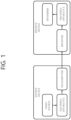
- the source device may include a video source, an encoding apparatus, and a transmitter.
- the receiving device may include a receiver, a decoding apparatus, and a renderer.
- the encoding apparatus may be called a video/image encoding apparatus, and the decoding apparatus may be called a video/image decoding apparatus.
- the transmitter may be included in the encoding apparatus.
- the receiver may be included in the decoding apparatus.
- the renderer may include a display, and the display may be configured as a separate device or an external component.
- the image partitioner 210, the predictor 220, the residual processor 230, the entropy encoder 240, the adder 250, and the filter 260 may be configured by one or more hardware components (e.g., encoder chipsets or processors) according to an embodiment.
- the memory 270 may include a decoded picture buffer (DPB), and may also be configured by a digital storage medium.
- the hardware component may further include the memory 270 as an internal/external component.
- the DPB of the memory 270 may store the modified reconstructed picture for use as the reference picture in the inter predictor 221.
- the memory 270 may store motion information of a block from which the motion information in the current picture is derived (or encoded) and/or motion information of blocks in the picture, having already been reconstructed.
- the stored motion information may be transferred to the inter predictor 221 to be utilized as motion information of the spatial neighboring block or motion information of the temporal neighboring block.
- the memory 270 may store reconstructed samples of reconstructed blocks in the current picture, and may transfer the reconstructed samples to the intra predictor 222.
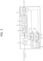
- the inter predictor 331 may construct a motion information candidate list based on neighboring blocks, and derive a motion vector of the current block and/or a reference picture index based on the received candidate selection information.
- Inter prediction may be performed based on various prediction modes, and the information on the prediction may include information indicating a mode of inter prediction for the current block.
- the adder 340 may generate a reconstructed signal (reconstructed picture, reconstructed block, or reconstructed sample array) by adding the obtained residual signal to the prediction signal (predicted block or predicted sample array) output from the predictor 330. If there is no residual for the processing target block, such as a case that a skip mode is applied, the predicted block may be used as the reconstructed block.
- the adder 340 may be called a reconstructor or a reconstructed block generator.
- the generated reconstructed signal may be used for the intra prediction of a next block to be processed in the current picture, and as described later, may also be output through filtering or may also be used for the inter prediction of a next picture.
- LMCS luma mapping with chroma scaling
- the filter 350 may improve subjective/objective image quality by applying filtering to the reconstructed signal.
- the filter 350 may generate a modified reconstructed picture by applying various filtering methods to the reconstructed picture, and store the modified reconstructed picture in the memory 360, specifically, in a DPB of the memory 360.
- the various filtering methods may include, for example, deblocking filtering, a sample adaptive offset, an adaptive loop filter, a bilateral filter, and the like.
- the (modified) reconstructed picture stored in the DPB of the memory 360 may be used as a reference picture in the inter predictor 331.
- the memory 360 may store the motion information of the block from which the motion information in the current picture is derived (or decoded) and/or the motion information of the blocks in the picture having already been reconstructed.
- the stored motion information may be transferred to the inter predictor 331 so as to be utilized as the motion information of the spatial neighboring block or the motion information of the temporal neighboring block.
- the memory 360 may store reconstructed samples of reconstructed blocks in the current picture, and transfer the reconstructed samples to the intra predictor 332.
- the embodiments described in the predictor 330, the dequantizer 321, the inverse transformer 322, and the filter 350 of the decoding apparatus 300 may also be applied in the same manner or corresponding to the predictor 220, the dequantizer 234, the inverse transformer 235, and the filter 260 of the encoding apparatus 200.
- a predicted block including prediction samples for a current block as a block to be coded (i.e., a coding target block) may be generated.
- the predicted block includes prediction samples in a spatial domain (or pixel domain).
- the predicted block is derived in the same manner in an encoding apparatus and a decoding apparatus, and the encoding apparatus may signal information (residual information) on residual between the original block and the predicted block, rather than an original sample value of an original block, to the decoding apparatus, thereby increasing image coding efficiency.
- the decoding apparatus may derive a residual block including residual samples based on the residual information, add the residual block and the predicted block to generate reconstructed blocks including reconstructed samples, and generate a reconstructed picture including the reconstructed blocks.
- the decoding apparatus may generate a reconstructed picture based on the predicted block and the residual block. Also, for reference for inter prediction of a picture afterward, the encoding apparatus may also dequantize/inverse-transform the quantized transform coefficients to derive a residual block and generate a reconstructed picture based thereon.
- At least one of quantization/dequantization and/or transform/inverse transform may be omitted.
- the quantized transform coefficient may be referred to as a transform coefficient.
- the transform coefficient may be called a coefficient or a residual coefficient or may still be called the transform coefficient for uniformity of expression.
- the quantized transform coefficient and the transform coefficient may be referred to as a transform coefficient and a scaled transform coefficient, respectively.
- the residual information may include information on transform coefficient(s), and the information on the transform coefficient(s) may be signaled through residual coding syntax.
- Transform coefficients may be derived based on the residual information (or information on the transform coefficient(s)), and scaled transform coefficients may be derived through inverse transform (scaling) on the transform coefficients.
- Residual samples may be derived based on inverse transform (transform) of the scaled transform coefficients. This may be applied/expressed in other parts of this document as well.
- the predictor of the encoding apparatus/decoding apparatus may derive prediction samples by performing inter prediction in units of blocks.
- Inter prediction can be a prediction derived in a manner that is dependent on data elements (e.g. sample values or motion information, etc) of picture(s) other than the current picture.
- the predicted block (prediction sample arrays) for the current block can be derived.
- the motion information of the current block may be predicted in units of blocks, subblocks, or samples based on the correlation between the motion information between neighboring blocks and the current block.
- the L0 motion vector may indicate a motion vector associated with the reference picture list L0 (L0), and the L1 motion vector may indicate a motion vector associated with the reference picture list L1 (L1).
- the reference picture list L0 may include pictures that are previous than the current picture in output order as reference pictures, and the reference picture list L1 may include pictures that are subsequent than the current picture in output order.
- the previous pictures may be called forward (reference) pictures, and the subsequent pictures may be called backward (reference) pictures.
- the reference picture list L0 may further include pictures that are subsequent than the current picture in output order as reference pictures. In this case, the previous pictures may be indexed first, and the subsequent pictures may be indexed next in the reference picture list L0.
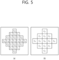
- the same filter coefficient may be allocated to two filter taps having the same value n and present at locations corresponding to each other with respect to the center filter tap.
- filter coefficients may be allocated to the 25 filter taps by using only 13 filter coefficients.
- filter coefficients C0 to C5 are allocated in the central symmetric shape. Therefore, filter coefficients may be allocated to the 13 filter taps by using only 7 filters.
- pps_beta_offset_div2 and pps_tc_offset_div2 specify the default deblocking parameter offsets for ⁇ and tC (divided by 2) that are applied for slices referring to the PPS, unless the default deblocking parameter offsets are overridden by the deblocking parameter offsets present in the slice headers of the slices referring to the PPS.
- the values of pps_beta_offset_div2 and pps_tc_offset_div2 shall both be in the range of -6 to 6, inclusive. When not present, the value of pps_beta_offset_div2 and pps_tc_offset_div2 are inferred to be equal to 0.
- ph_loop_filler_acrossvirtual_boundaries_disabled_present_flag 1 specifies that the in-loop filtering operations are disabled across the virtual boundaries in pictures associated to the PII.
- ph_loop_filter_across_virtual_boundaries disabled_present_flag 0 specifies that no such disabling of in-loop filtering operations is applied in pictures associated to the PH.
- the in-loop filtering operations include the deblocking filter, sample adaptive offset filter, and adaptive loop filter operations.
- ph_num_ver_virtual_boundaries specifies the number of ph_virtual_boundaries_pos_x[ i ] syntax elements that are present in the PH.
- ph_virtual_boundaries_x[ i ] is used to compute the value of VirtualBoundariesPosX[ i ], which specifies the location of the i-th vertical virtual boundary in units of luma samples.
- the value of ph_virtual _boundaries_pos_x[ i ] shall be in the range of 1 to Ceil( pic_width_in_luma_samples ⁇ 8 ) - 1, inclusive.
- ph_num_hor_virtual_boundaries specifies the number of ph_virtual_boundaries_pos_y[ i ] syntax elements that are present in the PH.
- ph_virtual_boundaries_pos_y[ i ] is used to compute the value of VirtualBoundariesPosY[ i ], which specifies the location of the i-th horizontal virtual boundary in units of luma samples.
- the value of ph_virtual_boundaries_pos_y[ i ] shall be in the range of 1 to Ceil( pic_height_in_luma_samples ⁇ 8 ) - 1, inclusive.
- pic_sao_enabled_present_flag 1 specifies that pic_sao_luma_flag and pic_sao_chroma_flag are present in the PH.
- pic_sao_enabled_present_flag 0 specifies that pic_sao_luma_flag and pic_sao_chroma_flag are not present in the PH.
- pic_sao_enabled_present_flag 1 specifies that SAO is enabled for the luma component in all slices associated with the PH
- pic_sao_luma_enabled_flag 0 specifies that SAO for the luma component may be disabled for one, or more, or all slices associated with the PH.
- pic_alf_enabled_present_flag 1 specifies that pic_alf_enabled_flag, pic_num_alf_aps_ids_luma, pic_alf_aps_id_luma[ i ], pic_alf_chroma_idc, and pic_alf_aps_id_chroma are present in the PH.
- pic_alf_enabled_present_flag 0 specifies that pic_alf_enabled_flag, pic_num_alf_aps_ids_luma, pic_alt_aps_id_luma[ i ], pic_alf_chroma_ide, and pic_alf_aps_id_chroma are not present in the PH.
- pic_alf_enabled_present_flag 1 specifies that adaptive loop filter is enabled for all slices associated with the PH and may be applied to Y, Cb, or Cr colour component in the slices.
- pic_alf_enabled_flag 0 specifies that adaptive loop filter may be disabled for one, or more, or all slices associated with the PH.
- pic_alf enabled flag is inferred to be equal to 0.
- pic_num_alf_aps_ids_luma specifies the number of ALF APSs that the slices associated with the PH refers to.
- pic_alf_aps_id_luma[ i ] specifies the adaptation_parameter_set_id of the i-th ALF APS that the luma component of the slices associated with the PH refers to.
- alf_luma_filter_signal_flag of the APS NAL unit having aps_params_type equal to ALF_APS and adaptation_parameter_set_id equal to pic_alf_aps_id_luma[ i ] shall be equal to 1.
- pic_alf_chroma_ide 0 specifies that the adaptive loop filter is not applied to Cb and Cr colour components.
- pic_alf_chroma_idc 1 indicates that the adaptive loop filter is applied to the Cb colour component.
- pic_alf_chroma_idc indicates that the adaptive loop filter is applied to the Cr colour component.
- pic_alf_chroma_ide 3 indicates that the adaptive loop filter is applied to Cb and Cr colour components.
- pic_alf_chroma_idc is not present, it is inferred to be equal to 0.
- pic_alf_aps_id_chroma specifies the adaptation_parameter_set_id of the ALF APS that the chroma component of the slices associated with the PH refers to.
- pic_deblocking_filter_override_present_flag 1 specifies that pic_deblocking_filter_override_flag is present in the PH.
- pic_deblocking_filter_override_present_flag 0 specifies that pic_deblocking_filter_override flag is not present in the PH. When pic_deblocking_filter_override_present_flag is not present, it is inferred to be equal to 0.
- pic_deblocking_filter_override_flag 1 specifies that deblocking parameters are present in the PH.
- pic_deblocking _filter_override_flag 0 specifies that deblocking parameters are not present in the PH. When not present, the value of pic_pic_deblocking_filter_override_flag is inferred to be equal to 0.
- pic_deblocking_filter_disabled_flag 1 specifies that the operation of the deblocking filter is not applied for the slices associated with the PH.
- pic_deblocking_filter_disabled_flag 0 specifies that the operation of the deblocking filter is applied for the slices associated with the PH.
- pic_beta_offset_div2 and pic_tc_offset_div2 specify the deblocking parameter offsets for ⁇ and tC (divided by 2) for the slices associated with the PH.
- pic_beta_offset_div2 and pic_tc_offset_div2 shall both be in the range of -6 to 6, inclusive. When not present, the values of pic_beta_offset_div2 and pic_tc_offset_div2 are inferred to be equal to pps_beta_offset_div2 and pps_tc_offset_div2, respectively.
- cu_chroma_qp_offset_enabled_flag 1 specifies that the cu_chroma_qp_offset flag may be present in the transform unit and palette coding syntax.
- cu_chroma_qp_offset_enabled_flag 0 specifies that the cu_chroma_qp_offset_flag is not present in the transform unit or palette coding syntax. When not present, the value of cu_chroma_qp_offset_enabled flag is inferred to be equal to 0.
- slice_sao_luma_flag 1 specifies that SAO is enabled for the luma component in the current slice; slice_sao_lumaflag equal to 0 specifies that SAO is disabled for the luma component in the current slice.
- slice_sao_luma_flag not present, it is inferred to be equal to pic_sao_luma_enabled_flag.
- slice_sao_chroma_flag 1 specifies that SAO is enabled for the chroma component in the current slice; slice_sao_chroma_flag equal to 0 specifies that SAO is disabled for the chroma component in the current slice.
- slice_sao_chroma_flag When slice_sao_chroma_flag is not present, it is inferred to be equal to pic_sao_chroma_enabled_flag.
- slice_alf_enabled_flag 1 specifies that adaptive loop filter is enabled and may be applied to Y, Cb, or Cr colour component in a slice.
- slice_alf_enabled _flag 0 specifies that adaptive loop filter is disabled for all colour components in a slice. When not present, the value of slice_alf_enabled_flag is inferred to be equal to pic_alf_enabled_flag.
- slice_num_alf_aps_ids_luma specifies the number of ALF APSs that the slice refers to.
- slice_alf_aps_id_luma[ i ] specifies the adaptation_parameter_set_id of the i-th ALF APS that the luma component of the slice refers to.
- the Temporalld of the APS NAL unit having aps_params_type equal to ALF_APS and adaptation_parameter_set_id equal to slice_alf_aps_id_luma[ i ] shall be less than or equal to the Temporalld of the coded slice NAL unit.
- slice_alf_enabled_flag is equal to 1 and slice_alf_aps_id_luma[ i ] is not present
- the value of slice_alf_aps_id_luma[ i ] is inferred to be equal to the value of pic_alf_aps_id_luma[ i ].
- alf_lumafilter_signal_flag of the APS NAL unit having aps_params_type equal to ALF_APS and adaptation_parameter_set_id equal to slice_alf_aps_id_luma[ i ] shall be equal to 1.
- slice_alf_chroma_idc 0 specifies that the adaptive loop filter is not applied to Cb and Cr colour components.
- slice_alf_chroma_idc 1 indicates that the adaptive loop filter is applied to the Cb colour component.
- slice_alf_chroma_idc indicates that the adaptive loop filter is applied to the Cr colour component.
- slice_alf_chroma_idc 3 indicates that the adaptive loop filter is applied to Cb and Cr colour components.
- slice_alf_chroma_idc is not present, it is inferred to be equal to pic_alf_chroma_idc.
- slice_alf_aps_id_chroma specifies the adaptation_parameter_set_id of the ALF APS that the chroma component of the slice refers to.
- the Temporalld of the APS NAL unit having aps_params_type equal to ALF_APS and adaptation_parameter_set_id equal to slice_alf_aps_id_chroma shall be less than or equal to the Temporalld of the coded slice NAL unit.
- slice_alf_enabled_flag is equal to 1 and slice_alf_aps_id_chroma is not present
- the value of slice_alf_aps_id_chroma is inferred to be equal to the value of pic_alf_aps_id_chroma.
- alf_chroma_filter_signal_flag of the APS NAL unit having aps_params_type equal to ALF_APS and adaptation_parameter_set_id equal to slice_alf aps_id_chroma shall be equal to 1.
- slice_deblocking_filter_override_flag 1 specifies that deblocking parameters are present in the slice header.
- slice_deblocking_filter_override_flag 0 specifies that deblocking parameters are not present in the slice header.
- the value of slice_deblocking_filter_override_flag is inferred to be equal to pic_deblocking_filter_override _flag.
- the SPS virtual boundaries present flag (sps_loop_filter_across_virtual_boundaries_disabled_present_flag) is set to 1, and thus a decoder expects signaling on locations of virtual boundaries, which may cause a problem in a decoding process.
- the signaling information for disabling the loop filter across the virtual boundaries may be included in the PH.
- positions of virtual boundaries e.g., vertical virtual boundaries, horizontal virtual boundaries
- variable(s) indicating whether a filter is disabled at virtual boundaries for the current picture may be derived.
- the variable(s) may include VirtualBoundariesDisabledFlag.
- the SPS virtual boundaries enabled flag (sps_loop_filter_across_virtual_boundaries_disabled_flag) is 1
- the SPS virtual boundaries present flag (sps_loop_filter_across_virtual_boundaries_disabled_present_flag) is 0, and a sum of information on the number of vertical virtual boundaries (e.g., ph_num_ver_virtual_boundaries) and information on the number of horizontal virtual boundaries (e.g., ph_num_hor_virtual_boundaries) is greater than 0, VirtualBoundariesDisabledFlag may be 1.
- VirtualBoundariesDisabledFlag may be 0.
- sps_loop_filter_across_virtual_boundaries_disabled_flag 1 specifies that the in-loop filtering operations are disabled across the virtual boundaries in pictures referring to the SPS.
- sps_loop_filter_across_virtual_boundaries_disabled_present_flag 0 specifies that no such disabling of in-loop filtering operations is applied in pictures referring to the SPS.
- In-loop filtering operations include the deblocking filter, sample adaptive offset filter, and adaptive loop filter operations.
- sps_loop_filter_across_virtual_boundaries_disabled_present_flag 1 specifies that the syntax elements for the in-loop filtering operations for the virtual boundaries is present in the SPS.
- sps_loop_filter_across_virtual_boundaries_disabled_flag 0 specifies that the syntax elements for the virtual boundaries in-loop filtering operations is not present in the SPS.
- In-loop filtering operations include the deblocking filter, sample adaptive offset filter, and adaptive loop filter operations.
- sps_loop_filter_acrossvirtual_boundaries_disabledflag is constraint to be 1 and sps_loop_filteracross_virtual_boundaries_disabled_present_flag is constraint to be 0.
- sps_num_ver_virtual_boundaries specifies the number of sps virtual_boundaries_pos_x[ i ] syntax elements that are present in the SPS. When sps_num_ver_virtual_boundaries is not present, it is inferred to be equal to 0.
- sps_virtual_boundaries_x [ i ] is used to compute the value of VirtualBoundariesPosX[ i ], which specifies the location of the i-th vertical virtual boundary in units of luma samples.
- sps_virtual_boundaries_pos_x[ i ] shall be in the range of 1 to Ceil( pic_width_in_luma_samples ⁇ 8 ) - 1, inclusive.
- sps _num _hor_ virtual_boundaries specifies the number of sps_virtual_boundaries_pos_y[ i ] syntax elements that are present in the SPS.
- sps_num_hor_virtual_boundaries When sps_num_hor_virtual_boundaries is not present, it is inferred to be equal to 0.
- sps_loop_filteracross_virtual_boundaries_disabled_flag When sps_loop_filteracross_virtual_boundaries_disabled_flag is equal to 1 and sps_loop_filteracross_virtual_boundaries_disabled_present_flag is equal to 1, the sum of sps_num_ver_virtual_boundaries and sps_num_hor_virtual_boundaries shall be greater than 0.
- sps_virtual_boundaries_pos_y [ i ] is used to compute the value of VirtualBoundariesPosY[ i ], which specifies the location of the i-th horizontal virtual boundary in units of luma samples.
- sps_virtual_boundaries_pos_y[ i ] shall be in the range of 1 to Ceil( pic_height_in_luma_samples ⁇ 8 ) - 1, inclusive.
- the following table shows an exemplary syntax of the header information (the picture header) according to the present embodiment.
- ph_num_ver_virtual_boundaries specifies the number of ph_virtual_boundaries_pos_x[ i ] syntax elements that are present in the PH. When ph_num_ver_virtual_boundaries is not present, it is inferred to be equal to 0.
- ph _ num _hor_virtual_boundaries specifies the number of ph_virtual_boundaries_pos_y[ i ] syntax elements that are present in the PH. When ph_num_hor virtual boundaries is not present, it is inferred to be equal to 0.
- VirtualBoundariesDisabledFlag 0 if( sps_loop_filter_across_virtual_boundaries_disabled_flag ) if( sps_loop_filter_across_virtual_boundaries_disabled_present_flag
- ( ph_num_ver_virtual_boundaries + ph_num_ver_virtual_boundaries > 0 ) ) VirtualBoundariesDisabledFlag 1
- ph_virtual_boundaries_pos_x[ i ] is used to compute the value of VirtualBoundariesPosX[ i ], which specifies the location of the i-th vertical virtual boundary in units of luma samples.
- ph_virtual_boundaries_pos_x[ i ] shall be in the range of 1 to Ceil( pic_width_in_luma_samples ⁇ 8) - 1, inclusive.
- the distance between any two vertical virtual_boundaries shall be greater than or equal to CtbSizeY luma samples.
- ph_num_hor_virtual_boundaries specifies the number of ph_virtual boundaries_pos_y[ i ] syntax elements that are present in the PH. When ph_num_hor_virtual_boundaries is not present, it is inferred to be equal to 0.
- image information obtained by the encoding apparatus and/or image information obtained through a bitstream received from the encoding apparatus to the decoding apparatus may include a sequence parameter set (SPS) and a picture header (PH).
- the SPS may include a virtual boundaries enabled flag (sps_loop_filter_across_virtual_boundaries_disabled_flag).
- the SPS may include an SPS virtual boundaries present flag (sps_loop_filter_across_virtual_boundaries_disabled_present_flag), based on the virtual boundaries enabled flag.
- the SPS may include the SPS virtual boundaries present flag.
- the SPS may include information on the number of SPS vertical virtual boundaries (sps_num_ver_virtual_boundaries), information on an SPS vertical virtual boundaries position (sps_virtual_boundaries_pos_x[i]), information on the number of SPS horizontal virtual boundaries (sps_num_hor_virtual_boundaries), and information on an SPS horizontal virtual boundaries position (sps_virtual_boundaries_pos_y[i]).
- the SPS may include information on the number of the SPS vertical virtual boundaries, information on the SPS vertical virtual boundaries position, information on the number of the SPS horizontal virtual boundaries, and information on the SPS horizontal virtual boundaries position.
- the number of pieces of information on the SPS vertical virtual boundaries position may be determined based on the information on the number of the SPS vertical virtual boundaries
- the number of pieces of information on the SPS horizontal virtual boundaries position may be determined based on the information on the number of the SPS horizontal virtual boundaries.
- the picture header may include information on the number of PH vertical virtual boundaries (ph_num_ver_virtual_boundaries), information on a PH vertical virtual boundaries position (ph_virtual_boundaries_pos_x[i]), information on the number of PH horizontal virtual boundaries (ph_num_hor_virtual_boundaries), and information on a PH horizontal virtual boundaries position (ph_virtual_boundaries_pos_y[i]).
- the picture header may include information on the number of the PH vertical virtual boundaries, information on the PH vertical virtual boundaries position, information on the number of the PH horizontal virtual boundaries, and information on the PH horizontal virtual boundary position.
- the number of pieces of information on the PH vertical virtual boundaries position may be determined based on the information on the number of the PH vertical virtual boundaries
- the number of pieces of information on the PH horizontal virtual boundaries position may be determined based on the information on the number of the PH horizontal virtual boundaries.
- each piece of information (picture headers) of pictures referring to the SPS may include a PH virtual boundaries present flag (ph_loop_filter_across_virtual_boundaries_disalbed_present_flag or ph_virtual_boundaries_present_flag).
- a sum of the number of vertical virtual boundaries and the number of horizontal virtual boundaries may be constraint to be greater than 0.
- variable(s) indicating whether a filter is disabled at virtual boundaries may be derived for the current picture.
- the variable(s) may include VirtualBoundariesDisabledFlag.
- VirtualBoundariesDisabledFlag may be 0.
- sps_loop_filter_across_virtual_boundaries_disabled_flag 1 specifies that the in-loop filtering operations are disabled across the virtual boundaries in pictures referring to the SPS.
- sps_loop_filter_across_virtual_boundaries_disabled_present_flag 0 specifies that no such disabling of in-loop filtering operations is applied in pictures referring to the SPS.
- In-loop filtering operations include the deblocking filter, sample adaptive offset filter, and adaptive loop filter operations.
- sps_loop_filter_across_virtual_boundaries_disabled_present_flag 1 specifies that the syntax elements for the in-loop filtering operations for the virtual boundaries is present in the SPS.
- sps_loop_filter_across_virtual_boundaries_disabled_present_flag 0 specifies that the syntax elements for the virtual boundaries in-loop filtering operations is not present in the SPS.
- In-loop filtering operations include the deblocking filter, sample adaptive offset filter, and adaptive loop filter operations.
- sps_loop_filter_across_virtual_boundaries_disabled_flag is constraint to be 1 and sps_loop_filter_across_virtual_boundaries_disabled_present_flag is constraint to be 0.
- sps_num_ver_virtual_boundaries specifies the number of sps_virtual_boundaries_pos_x[ i ] syntax elements that are present in the SPS. When sps_num_ver_virtual_boundaries is not present, it is inferred to be equal to 0.
- sps_virtual_boundaries_pos _x[ i ] is used to compute the value of VirtualBoundariesPosX[ i ], which specifies the location of the i-th vertical virtual boundary in units of luma samples.
- sps_boundaries_pos_x[ i ] shall be in the range of 1 to Ceil( pic_width_in_luma_samples ⁇ 8 ) - 1, inclusive.
- sps_num_hor_virtual_boundaries specifies the number of sps_virtual_boundaries_pos_y[ i ] syntax elements that are present in the SPS.
- sps_num_hor_virtual_boundaries When sps_num_hor_virtual_boundaries is not present, it is inferred to be equal to 0.
- sps_loop_filter_across_virtual_boundaries_disabled_flag When sps_loop_filter_across_virtual_boundaries_disabled_flag is equal to 1 and sps_loop filter_across_virtual_boundaries_disabled_present_flag is equal to 1, the sum of sps_num_ver_virtual_boundaries and sps_num_hor_virtual_boundaries shall be greater than 0.
- sps_num_ver_virtual_boundaries specifies the number of sps_virtual_boundaries_pos_x[ i ] syntax elements that are present in the SPS. When sps_num_ver_virtual_boundaries is not present, it is inferred to be equal to 0. sps_virtual_boundaries_pos_x[ i ] is used to compute the value of VirtualBoundariesPosX[ i ], which specifies the location of the i-th vertical virtual boundary in units of luma samples.
- sps_virtual_boundaries_pos_x[ i ] shall be in the range of 1 to Ceil( pic_width_inluma_samples ⁇ 8 ) - 1, inclusive.
- sps_num_hor_virtual_boundaries specifies the number of sps_virtual_boundaries_pos_y[ i ] syntax elements that are present in the SPS. When sps_num_hor_virtual_boundaries is not present, it is inferred to be equal to 0.
- sps_loop_filter_across_virtual_boundaries_disabled_present_flag When sps_loop_filter_across_virtual_boundaries_disabled_present_flag is equal to 1, the sum of sps_num_ver_virtual_boundaries and sps_num_hor_virtual_boundaries shall be greater than 0.
- sps_virtual boundaries i ] is used to compute the value of VirtualBoundariesPosY[ i ], which specifies the location of the i-th horizontal virtual boundary in units of luma samples.
- sps_virtual_boundaries_pos_y[ i ] shall be in the range of 1 to Ceil( pic_height_in_luma_samples ⁇ 8) - 1, inclusive.
- sps_ph_loop_filter_across_virtual_boundaries_disabled_present_flag is inferred to be equal to 0
- gdr_enabled_flag is equal to 1
- sps_loop_filter_across_virtual_boundaries_disabled_present_flag is constrained to be equal to 0
- sps_ph_loop_filter_across_virtual_boundaries_disabled_present_flag is constrained to be 1.
- sps_virtual_boundaries_pos_x[ i ] is used to compute the value of VirtualBoundariesPosX[ i ], which specifies the location of the i-th vertical virtual boundary in units of luma samples.
- sps_virtual_boundaries_pos_x[ i ] shall be in the range of 1 to Ceil( pic_width_in_luma_samples ⁇ 8 ) - 1, inclusive.
- sps_num_hor_virtual_boundaries specifies the number of sps_virtual_boundaries_pos_y[ i ] syntax elements that are present in the SPS.
- sps_num_hor_virtual_boundaries When sps_num_hor_virtual_boundaries is not present, it is inferred to be equal to 0. When sps_loop_filteracross virtual boundaries_disabled_flag is equal to 1 and sps_loop_ filter across virtual boundaries disabled present flag is equal to 1, the sum of sps_num_ver_virtual_boundaries and sps_num_hor_virtual_boundaries shall be greater than 0.
- sps_virtual_boundaries_pos_y[ i ] is used to compute the value of VirtualBoundariesPosY[ i ], which specifies the location of the i-th horizontal virtual boundary in units of luma samples. sps_virtual_boundaries_pos_y[ i ] shall be in the range of 1 to Ceil( pic_height_in_luma_samples ⁇ 8) - 1, inclusive.
- the following table shows an exemplary syntax of the header information (the picture header) according to the present embodiment.
- ph_loop_filter_across_virtual_boundaries_disabled_present_flag 1 specifies that the in-loop filtering operations are disabled across the virtual boundaries in pictures associated to the PH.
- ph_loop_filter_across_virtual boundaries_disabled _present flag 0 specifies that no such disabling of in-loop filtering operations is applied in pictures associated to the PH.
- the in-loop filtering operations include the deblocking filter, sample adaptive offset filter, and adaptive loop filter operations.
- ph_loop_filter_across_virtual_boundaries_disabled_present_flag Alternatively, the following constraint may be specified: When sps_loop_filter_across_virtual_boundaries_disabled_flag is equal to 1 and sps__loop _filter_across virtual boundaries _disabled_present_flag is equal to 0, ph_l
- ph_virtual_boundaries_pos_x[ i] is used to compute the value of VirtualBoundariesPosX[ i ], which specifies the location of the i-th vertical virtual boundary in units of luma samples.
- ph_virtual_boundaries_pos_x[ i ] shall be in the range of 1 to Ceil( pic_width_in_luma samples ⁇ 8) - 1, inclusive.
- VirtualBoundariesPosX[ i ] ( i ⁇ sps_num_ver_virtual_boundaries ) ?
- the distance between any two vertical virtual boundaries shall be greater than or equal to CtbSizeY luma samples.
- ph_num_hor_virtual_boundaries specifies the number of ph_virtual _boundaries_pos_y[ i ] syntax elements that are present in the PH.
- ph virtual _boundaries_pos_y[ i ] shall be in the range of 1 to Ceil( pic_height_in luma samples ⁇ 8) - 1, inclusive.
- the location of the horizontal virtual boundary VirtualBoundariesPosY[ i ] is derived as follows:
- the distance between any two horizontal virtual boundaries shall be greater than or equal to CtbSizeY luma samples
- sps_loop_filter_across_virtual_boundaries_disabled_flag is equal to 1 and ph_loop_filter_across_virtual_boundaries_disabled_present_flag is equal to 1, the sum of ph_num_ver_virtual_boundaries and ph_num_hor_virtual_boundaries shall be greater than 0.
- image information obtained by the encoding apparatus and/or image information obtained through a bitstream received from the encoding apparatus to the decoding apparatus may include a sequence parameter set (SPS) and a picture header (PH).
- the SPS may include a virtual boundaries enabled flag (sps_loop_filter_across_virtual_boundaries_disabled_flag).
- the SPS may include an SPS virtual boundaries present flag (sps_loop_filter_across_virtual_boundaries_disabled_present_flag), based on the virtual boundaries enabled flag. For example, when a value of the virtual boundaries enabled flag is 1, the SPS may include the SPS virtual boundaries present flag.
- the SPS may include information on the number of SPS vertical virtual boundaries (sps_num_ver_virtual_boundaries), information on an SPS vertical virtual boundaries position (sps_virtual_boundaries_pos_x[i]), information on the number of SPS horizontal virtual boundaries (sps_num_hor_virtual_boundaries), and information on an SPS horizontal virtual boundaries position (sps_virtual_boundaries_pos_y[i]).
- the SPS may include information on the number of the SPS vertical virtual boundaries, information on the SPS vertical virtual boundaries position, information on the number of the SPS horizontal virtual boundaries, and information on the SPS horizontal virtual boundaries position.
- the number of pieces of information on the SPS vertical virtual boundaries position may be determined based on the information on the number of the SPS vertical virtual boundaries
- the number of pieces of information on the SPS horizontal virtual boundaries position may be determined based on the information on the number of the SPS horizontal virtual boundaries.
- the picture header may include a PH virtual boundaries present flag, based on the virtual boundaries enabled flag.
- sps_num_hor_virtual_boundaries When sps_num_hor_virtual_boundaries is not present, it is inferred to be equal to 0.
- sps_loop_filter_across_virtual_boundaries_disabled_flag When sps_loop_filter_across_virtual_boundaries_disabled_flag is equal to 1 and sps_loop_filter_across_virtual_boundaries_disabled_present_flag is equal to 1, the sum of sps_num_ver_virtual_boundaries and sps_num_hor_virtual_boundaries shall be greater than 0.
- the picture header may include information on the number of the PH horizontal virtual boundaries.
- the picture header may include information on a delta value of a PH horizontal virtual boundaries position (ph_virtual_boundaries_pos_y_delta[i]) and information on a sign of the PH horizontal virtual boundaries position (ph_virtual_boundaries_pos_y_sign[i]).
- the number of pieces of information on the PH horizontal virtual boundaries position delta value and the number of pieces of information on a sign of the PH horizontal virtual boundaries position may be determined.
- the encoding apparatus may derive transform coefficients.
- the encoding apparatus may derive the transform coefficients, based on a transform process for the residual samples.
- the transform process may include at least one of a discrete cosine transform (DCT), a discrete sine transform (DST), a graph-based transform (GBT), and a conditionally non-linear transform (CNT).
- DCT discrete cosine transform
- DST discrete sine transform
- GBT graph-based transform
- CNT conditionally non-linear transform
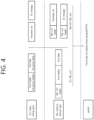
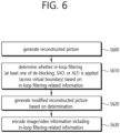
- the encoding apparatus may generate residual information (S810).
- the encoding apparatus may generate the residual information, based on the transform coefficients.
- the encoding apparatus may generate residual information indicating the quantized transform coefficients.
- the residual information may be generated through various encoding methods such as exponential Golomb, CAVLC, CABAC, or the like.
- the encoding apparatus may determine whether the in-loop filtering process is performed across virtual boundaries (S820).
- the virtual boundaries may be the same as the aforementioned virtual boundaries.
- the in-loop filtering process may include at least one of a deblocking process, an SAO process, and an ALF process.
- the encoding apparatus may generate information related to a virtual boundary (S830).
- the encoding apparatus may generate the information related to the virtual boundary, based on the determination of the step S820.
- the information related to the virtual boundary may be included in information related to in-loop filtering.
- the information related to the in-loop filtering may refer to information used to perform the in-loop filtering process.
- the information related to the virtual boundary may include the aforementioned information on virtual boundaries (the SPS virtual boundaries enabled flag, the picture header virtual boundaries enabled flag, the SPS virtual boundaries present flag, the picture header virtual boundaries present flag, information on positions of virtual boundaries, etc.).
- the encoding apparatus may encode video/image information (S840).
- the image information may include residual information, prediction-related information, and/or in-loop filtering-related information.
- the encoded video/image information may be output in the form of a bitstream.
- the bitstream may be transmitted to a decoding apparatus through a network or a storage medium.
- the image/video information may include a variety of information according to an embodiment of the present document.
- the image/video may include information disclosed in at least one of the tables 1 to 32 above.
- the image information may include an SPS, and picture header information referring to the SPS.
- the information related to the virtual boundaries may include a virtual boundaries enabled flag (or an SPS virtual boundaries enabled flag). Whether signaling of the information related to the virtual boundaries is present in the picture header information may be determined based on the virtual boundaries enabled flag.
- the in-loop filtering process may be performed across the virtual boundaries, based on the virtual boundaries enable flag (or may not be performed across the virtual boundaries). For example, the virtual boundaries enabled flag may indicate whether it is possible to disable the in-loop filtering process across the virtual boundaries.
- the SPS may include the virtual boundaries enabled flag and an SPS virtual boundaries present flag. In addition, whether information on positions of the virtual boundaries and information on the number of virtual boundaries are included in the SPS may be determined based on the SPS virtual boundaries present flag.
- the SPS may include information on the number of vertical virtual boundaries, based on that a value of the SPS virtual boundaries present flag is 1.
- the picture header information may include information on the number of vertical virtual boundaries, based on that a value of the picture header virtual boundaries present flag is 1.
- the picture header information may include information on the number of horizontal virtual boundaries, based on that a value of the picture header virtual boundaries present flag is 1.
- the picture header information may include information on positions of the horizontal virtual boundaries.
- the number of pieces of the information on positions of the horizontal virtual boundaries may be determined based on the information on the number of horizontal virtual boundaries.
- a sum of the number of vertical virtual boundaries and the number of horizontal virtual boundaries may be greater than 0, based on that the SPS includes information on positions of the vertical virtual boundaries and information on positions of the horizontal virtual boundaries.
- the information related to in-loop filtering may further include an SPS virtual boundaries present flag, a picture header virtual boundaries present flag, and a gradual decoding refresh (GDR) enabled flag.
- GDR gradual decoding refresh
- a value of the GDR enabled flag is 1, a value of the SPS virtual boundaries enabled flag (the virtual boundaries enabled flag) may be 1, a value of the SPS virtual boundaries present flag may be 0, and a value of the picture header virtual boundaries present flag may be 1 (signaling of information of the virtual boundaries may be present in the picture header).
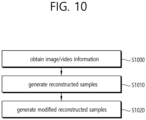
- FIG. 10 and FIG. 11 schematically show an example of a video/image decoding method and related components according to embodiment(s) of the present document.
- the method disclosed in FIG. 10 may be performed by the decoding apparatus disclosed in FIG. 3 or FIG. 11 .
- S1000 of FIG. 10 may be performed by an entropy decoder 310 of the decoding apparatus
- S1010 may be performed by a residual processor 320 and/or adder 340 of the decoding apparatus
- S1020 may be performed by a filter 350 of the decoding apparatus.
- the method disclosed in FIG. 10 may include the aforementioned embodiments in the present document.
- the decoding apparatus may receive/obtain the video/image information (S1000).
- the video/image information may include residual information, prediction-related information, and/or in-loop filtering-related information.
- the decoding apparatus may receive/obtain the image/video information through a bitstream.
- the image/video information may include a variety of information according to an embodiment of the present document.
- the image/video may include information disclosed in at least one of the tables 1 to 32 above.
- the decoding apparatus may derive quantized transform coefficients.
- the decoding apparatus may derive the quantized transform coefficients, based on the residual information.
- the quantized transform coefficients may have a 1-dimensional vector form, based on a coefficient scan order.
- Quantized transform coefficients may include quantized luma transform coefficients and/or quantized chroma transform coefficients.
- the decoding apparatus may derive the transform coefficients.
- the decoding apparatus may derive the transform coefficients, based on a dequantization process for the quantized transform coefficients.
- the decoding apparatus may derive luma transform coefficients through dequantization, based on the quantized luma transform coefficients.
- the decoding apparatus may derive chroma transform coefficients through dequantization, based on the quantized chroma transform coefficients.
- the decoding apparatus may generate/derive residual samples.
- the decoding apparatus may derive the residual samples, based on the inverse-transform process for the transform coefficients.
- the decoding apparatus may derive residual luma samples through the inverse-transform process, based on the luma transform coefficients.
- the decoding apparatus may derive residual chroma samples through the inverse-transform, based on the chroma transform coefficients.
- the decoding apparatus may generate/derive reconstructed samples (S1010).
- the decoding apparatus may generate/derive reconstructed luma samples and/or reconstructed chroma samples.
- the decoding apparatus may generate the reconstructed luma samples and/or the reconstructed chroma samples, based on the residual information.
- the decoding apparatus may generate reconstructed samples, based on the residual information.
- the reconstructed samples may include the reconstructed luma samples and/or the reconstructed chroma samples.
- a luma component of the reconstructed samples may correspond to the reconstructed luma samples
- a chroma component of the reconstructed samples may correspond to the reconstructed chroma samples.
- the decoding apparatus may generate prediction luma samples and/or prediction chroma samples through a prediction process.
- the decoding apparatus may generate the reconstructed luma samples, based on the prediction luma samples and the residual luma samples.
- the decoding apparatus may generate the reconstruction chroma samples, based on the prediction chroma samples and the residual chroma samples.
- the decoding apparatus may generate modified (filtered) reconstructed samples (S1020).
- the decoding apparatus may generate the modified reconstructed samples by performing an in-loop filtering process for the reconstructed samples of the current picture.
- the decoding apparatus may generate the modified reconstructed samples, based on in-loop filtering-related information (and/or virtual boundaries-related information).
- the decoding apparatus may use a deblocking process, an SAO process, and/or an ALF process to generate the modified reconstructed samples.
- the image information may include a sequence parameter set (SPS), and picture header information referring to the SPS.
- the information related to the virtual boundaries may include a virtual boundaries enabled flag (or an SPS virtual boundaries enabled flag). Whether signaling of the information related to the virtual boundaries is present in the picture header information may be determined based on the virtual boundaries enabled flag.
- the in-loop filtering process may be performed across the virtual boundaries, based on the virtual boundaries enable flag (or may not be performed across the virtual boundaries). For example, the virtual boundaries enabled flag may indicate whether it is possible to disable the in-loop filtering process across the virtual boundaries.
- the SPS may include a virtual boundaries enabled flag and/or an SPS virtual boundaries present flag. For example, whether information on positions of the virtual boundaries and information on the number of virtual boundaries are included in the SPS may be determined based on the SPS virtual boundaries present flag.
- the SPS may include information on the number of vertical virtual boundaries, based on that a value of the SPS virtual boundaries present flag is 1.
- the SPS may include information on the number of horizontal virtual boundaries, based on that a value of the SPS virtual boundaries present flag is 1.
Landscapes
- Engineering & Computer Science (AREA)
- Multimedia (AREA)
- Signal Processing (AREA)
- Compression Or Coding Systems Of Tv Signals (AREA)
- Compression, Expansion, Code Conversion, And Decoders (AREA)
Claims (4)
- Bilddecodierverfahren, das von einer Decodiervorrichtung (300) durchgeführt wird, wobei das Verfahren Folgendes umfasst:Erhalten (S1000) von Bildinformationen, die Restinformationen und vorhersagebezogene Informationen enthalten, über einen Bitstrom;Erzeugen von Restabtastwerten basierend auf den Restinformationen;Ableiten von Vorhersageabtastwerten basierend auf den vorhersagebezogenen Informationen;Erzeugen (S1010) von rekonstruierten Abtastwerten eines aktuellen Bildes basierend auf den Vorhersageabtastwerten und den Restabtastwerten; undErzeugen (S1020) von modifizierten rekonstruierten Abtastwerten basierend auf einem In-Loop-Filterungsprozess für die rekonstruierten Abtastwerte,wobei die Bildinformationen einen Sequenzparametersatz (SPS) enthalten,wobei der SPS ein Flag "virtuelle Grenzen aktiviert" enthält,dadurch gekennzeichnet, dass der SPS ein SPS-Flag "virtuelle Grenzen vorhanden" basierend auf einem Wert des Flags "virtuelle Grenzen aktiviert" enthält, der gleich 1 ist,wobei der SPS Informationen über Positionen vertikaler virtueller Grenzen, Informationen über eine Anzahl der vertikalen virtuellen Grenzen, Informationen über Positionen horizontaler virtueller Grenzen und Informationen über eine Anzahl der horizontalen virtuellen Grenzen enthält, basierend auf dem Wert des Flags "virtuelle Grenzen aktiviert", der gleich 1 ist, und einem Wert des SPS-Flags "virtuelle Grenzen vorhanden", der gleich 1 ist, undwobei basierend auf dem Flag "virtuelle Grenzen aktiviert" bestimmt wird, ob der In-Loop-Filterungsprozess über virtuelle Grenzen hinweg durchgeführt wird.
- Bildcodierungsverfahren, das von einer Codiervorrichtung (200) durchgeführt wird und Folgendes umfasst: Ableiten von vorhersagebezogenen Informationen für einen aktuellen Block;Erzeugen von Vorhersageabtastwerten des aktuellen Blocks basierend auf den vorhersagebezogenen Informationen;Ableiten (S800) von Restabtastwerten des aktuellen Blocks basierend auf den Vorhersageabtastwerten;Erzeugen (S810) von Restinformationen basierend auf den Restabtastwerten für den aktuellen Block;Erzeugen von rekonstruierten Abtastwerten für ein aktuelles Bild basierend auf den Vorhersageabtastwerten und den Restabtastwerten;Erzeugen (S830) von Informationen in Bezug auf einen In-Loop-Filterungsprozess für die rekonstruierten Abtastwerte; undCodieren (S840) von Bildinformationen, die die vorhersagebezogenen Informationen, die Restinformationen und die Informationen in Bezug auf den In-Loop-Filterungsprozess enthalten,wobei die Bildinformationen einen Sequenzparametersatz (SPS) enthalten,wobei der SPS ein Flag "virtuelle Grenzen aktiviert" enthält,dadurch gekennzeichnet, dass der SPS ein SPS-Flag "virtuelle Grenzen vorhanden" basierend auf einem Wert des Flags "virtuelle Grenzen aktiviert" enthält, der gleich 1 ist,wobei der SPS Informationen über Positionen vertikaler virtueller Grenzen, Informationen über eine Anzahl der vertikalen virtuellen Grenzen, Informationen über Positionen horizontaler virtueller Grenzen und Informationen über eine Anzahl der horizontalen virtuellen Grenzen enthält, basierend auf dem Wert des Flags "virtuelle Grenzen aktiviert", der gleich 1 ist, und einem Wert des SPS-Flags "virtuelle Grenzen vorhanden", der gleich 1 ist, undwobei der Wert des Flags "virtuelle Grenzen aktiviert" basierend darauf bestimmt wird, ob der In-Loop-Filterungsprozess über virtuelle Grenzen hinweg durchgeführt wird.
- Computerlesbares Speichermedium, das einen von einem Bildcodierungsverfahren erzeugten Bitstrom speichert, wobei das Verfahren Folgendes umfasst:Ableiten von vorhersagebezogenen Informationen für einen aktuellen Block;Erzeugen von Vorhersageabtastwerten des aktuellen Blocks basierend auf den vorhersagebezogenen Informationen;Ableiten von Restabtastwerten für den aktuellen Block basierend auf den Vorhersageabtastwerten;Erzeugen von Restinformationen basierend auf den Restabtastwerten für den aktuellen Block;Erzeugen von rekonstruierten Abtastwerten für ein aktuelles Bild basierend auf den Vorhersageabtastwerten und den Restabtastwerten;Erzeugen von Informationen in Bezug auf einen In-Loop-Filterungsprozess für die rekonstruierten Abtastwerte; undCodieren von Bildinformationen, die die vorhersagebezogenen Informationen, die Restinformationen und die Informationen in Bezug auf den In-Loop-Filterungsprozess enthalten,wobei die Bildinformationen einen Sequenzparametersatz (SPS) enthalten,wobei der SPS ein Flag "virtuelle Grenzen aktiviert" enthält,dadurch gekennzeichnet, dass der SPS ein SPS-Flag "virtuelle Grenzen vorhanden" basierend auf einem Wert des Flags "virtuelle Grenzen aktiviert" enthält, der gleich 1 ist,wobei der SPS Informationen über Positionen vertikaler virtueller Grenzen, Informationen über eine Anzahl der vertikalen virtuellen Grenzen, Informationen über Positionen horizontaler virtueller Grenzen und Informationen über eine Anzahl der horizontalen virtuellen Grenzen enthält,basierend auf dem Wert des Flags "virtuelle Grenzen aktiviert", der gleich 1 ist, und einem Wert des SPS-Flags "virtuelle Grenzen vorhanden", der gleich 1 ist, undwobei der Wert des Flags "virtuelle Grenzen aktiviert" basierend darauf bestimmt wird, ob der In-Loop-Filterungsprozess über virtuelle Grenzen hinweg durchgeführt wird.
- Übertragungsverfahren von Daten für ein Bild, wobei das Verfahren Folgendes umfasst:Erhalten eines Bitstroms für das Bild, wobei der Bitstrom basierend auf dem Ableiten von vorhersagebezogenen Informationen für einen aktuellen Block, dem Erzeugen von Vorhersageabtastwerten für den aktuellen Block basierend auf den vorhersagebezogenen Informationen, dem Ableiten von Restabtastwerten für den aktuellen Block basierend auf den Vorhersageabtastwerten, dem Erzeugen von Restinformationen basierend auf den Restabtastwerten für den aktuellen Block, dem Erzeugen von rekonstruierten Abtastwerten für ein aktuelles Bild basierend auf den Vorhersageabtastwerten und den Restabtastwerten, dem Erzeugen von Informationen in Bezug auf einen In-Loop-Filterungsprozess für die rekonstruierten Abtastwerte und dem Codieren von Bildinformationen, die die vorhersagebezogenen Informationen, die Restinformationen und die Informationen in Bezug auf den In-Loop-Filterungsprozess enthalten, erzeugt wird; undÜbertragen der Daten, die den Bitstrom umfassen,wobei die Bildinformationen einen Sequenzparametersatz (SPS) enthalten,wobei der SPS ein Flag "virtuelle Grenzen aktiviert" enthält,dadurch gekennzeichnet, dass der SPS ein SPS-Flag "virtuelle Grenzen vorhanden" basierend auf einem Wert des Flags "virtuelle Grenzen aktiviert" enthält, der gleich 1 ist,wobei der SPS Informationen über Positionen vertikaler virtueller Grenzen, Informationen über eine Anzahl der vertikalen virtuellen Grenzen, Informationen über Positionen horizontaler virtueller Grenzen und Informationen über eine Anzahl der horizontalen virtuellen Grenzen enthält, basierend auf dem Wert des Flags "virtuelle Grenzen aktiviert", der gleich 1 ist, und einem Wert des SPS-Flags "virtuelle Grenzen vorhanden", der gleich 1 ist, undwobei der Wert des Flags "virtuelle Grenzen aktiviert" basierend darauf bestimmt wird, ob der In-Loop-Filterungsprozess über virtuelle Grenzen hinweg durchgeführt wird.
Priority Applications (3)
| Application Number | Priority Date | Filing Date | Title |
|---|---|---|---|
| RS20250755A RS67059B1 (sr) | 2019-11-18 | 2020-11-17 | Uređaj za kodiranje slike i postupak za kontrolu filtriranja u petlji |
| HRP20250927TT HRP20250927T1 (hr) | 2019-11-18 | 2020-11-17 | Uređaj za kodiranje slike i postupak za upravljanje filtriranjem petlje |
| EP25180395.3A EP4593396A3 (de) | 2019-11-18 | 2020-11-17 | Bildcodierungsvorrichtung und verfahren zur steuerung der schleifenfilterung |
Applications Claiming Priority (2)
| Application Number | Priority Date | Filing Date | Title |
|---|---|---|---|
| US201962937234P | 2019-11-18 | 2019-11-18 | |
| PCT/KR2020/016137 WO2021101200A1 (ko) | 2019-11-18 | 2020-11-17 | 루프 필터링을 제어하기 위한 영상 코딩 장치 및 방법 |
Related Child Applications (2)
| Application Number | Title | Priority Date | Filing Date |
|---|---|---|---|
| EP25180395.3A Division EP4593396A3 (de) | 2019-11-18 | 2020-11-17 | Bildcodierungsvorrichtung und verfahren zur steuerung der schleifenfilterung |
| EP25180395.3A Division-Into EP4593396A3 (de) | 2019-11-18 | 2020-11-17 | Bildcodierungsvorrichtung und verfahren zur steuerung der schleifenfilterung |
Publications (4)
| Publication Number | Publication Date |
|---|---|
| EP4064708A1 EP4064708A1 (de) | 2022-09-28 |
| EP4064708A4 EP4064708A4 (de) | 2023-11-22 |
| EP4064708C0 EP4064708C0 (de) | 2025-07-09 |
| EP4064708B1 true EP4064708B1 (de) | 2025-07-09 |
Family
ID=75980907
Family Applications (2)
| Application Number | Title | Priority Date | Filing Date |
|---|---|---|---|
| EP25180395.3A Pending EP4593396A3 (de) | 2019-11-18 | 2020-11-17 | Bildcodierungsvorrichtung und verfahren zur steuerung der schleifenfilterung |
| EP20891070.3A Active EP4064708B1 (de) | 2019-11-18 | 2020-11-17 | Bildcodierungsvorrichtung und verfahren zum steuern von schleifenfilterung |
Family Applications Before (1)
| Application Number | Title | Priority Date | Filing Date |
|---|---|---|---|
| EP25180395.3A Pending EP4593396A3 (de) | 2019-11-18 | 2020-11-17 | Bildcodierungsvorrichtung und verfahren zur steuerung der schleifenfilterung |
Country Status (12)
| Country | Link |
|---|---|
| US (2) | US12323632B2 (de) |
| EP (2) | EP4593396A3 (de) |
| JP (4) | JP7392144B2 (de) |
| KR (2) | KR20250152677A (de) |
| CN (5) | CN120017853A (de) |
| BR (1) | BR112022009619A2 (de) |
| ES (1) | ES3037849T3 (de) |
| HR (1) | HRP20250927T1 (de) |
| MX (5) | MX2022005989A (de) |
| PL (1) | PL4064708T3 (de) |
| RS (1) | RS67059B1 (de) |
| WO (1) | WO2021101200A1 (de) |
Families Citing this family (3)
| Publication number | Priority date | Publication date | Assignee | Title |
|---|---|---|---|---|
| MX2022005993A (es) * | 2019-11-18 | 2022-09-07 | Lg Electronics Inc | Dispositivo y metodo de codificacion de imagenes para controlar el filtrado en bucle. |
| AU2020388338B2 (en) * | 2019-11-18 | 2024-04-11 | Lg Electronics Inc. | Image coding apparatus and method based on signaling of information for filtering |
| KR102788065B1 (ko) | 2020-02-14 | 2025-03-31 | 두인 비전 컴퍼니 리미티드 | 비디오 비트스트림내에 서브픽처 정보 (subpicture information) 시그널링 |
Family Cites Families (25)
| Publication number | Priority date | Publication date | Assignee | Title |
|---|---|---|---|---|
| WO2004008747A2 (en) * | 2002-07-16 | 2004-01-22 | Thomson Licensing S.A. | Interleaving of base and enhancement layers for hd-dvd |
| JP5344238B2 (ja) | 2009-07-31 | 2013-11-20 | ソニー株式会社 | 画像符号化装置および方法、記録媒体、並びにプログラム |
| US9001883B2 (en) | 2011-02-16 | 2015-04-07 | Mediatek Inc | Method and apparatus for slice common information sharing |
| CN103503456B (zh) | 2011-05-10 | 2017-03-22 | 联发科技股份有限公司 | 用于重建视频的环内处理方法及其装置 |
| KR101462052B1 (ko) | 2011-11-09 | 2014-11-20 | 에스케이 텔레콤주식회사 | 변환을 이용한 주파수 도메인 상의 적응적 루프 필터를 이용한 영상 부호화/복호화 방법 및 장치 |
| CN103200400B (zh) * | 2012-01-09 | 2018-03-16 | 中兴通讯股份有限公司 | 一种图像层和分片层的编解码方法、编解码器和电子设备 |
| JP2013236358A (ja) | 2012-03-14 | 2013-11-21 | Sharp Corp | 画像フィルタ装置、画像復号装置、画像符号化装置、およびデータ構造 |
| US8983218B2 (en) * | 2012-04-11 | 2015-03-17 | Texas Instruments Incorporated | Virtual boundary processing simplification for adaptive loop filtering (ALF) in video coding |
| GB2516824A (en) | 2013-07-23 | 2015-02-11 | Nokia Corp | An apparatus, a method and a computer program for video coding and decoding |
| US10440397B2 (en) * | 2014-03-31 | 2019-10-08 | Sony Corporation | Image decoding device and method |
| US10356415B2 (en) | 2014-06-20 | 2019-07-16 | Qualcomm Incorporated | Systems and methods for constraining representation format parameters for a parameter set |
| KR101809630B1 (ko) * | 2015-06-11 | 2017-12-15 | 인텔렉추얼디스커버리 주식회사 | 적응적인 디블록킹 필터링에 관한 부호화/복호화 방법 및 장치 |
| EP3310058B1 (de) * | 2015-06-12 | 2023-02-22 | Panasonic Intellectual Property Management Co., Ltd. | Bildverschlüsselungsverfahren, bildentschlüsselungsverfahren, bildverschlüsselungsvorrichtung und bildentschlüsselungsvorrichtung |
| WO2016204462A1 (ko) | 2015-06-16 | 2016-12-22 | 엘지전자(주) | 영상의 부호화/복호화 방법 및 이를 위한 장치 |
| US10701383B2 (en) | 2015-06-16 | 2020-06-30 | Lg Electronics Inc. | Method for encoding/decoding image and device for same |
| KR102160667B1 (ko) | 2015-09-10 | 2020-09-28 | 엘지전자 주식회사 | 비디오 코딩 시스템에서 인트라 예측 방법 및 장치 |
| EP3358848B1 (de) | 2015-09-29 | 2021-04-21 | LG Electronics Inc. | Verfahren zum filtern eines bildes in einem bildcodierungssystem |
| US20170272758A1 (en) | 2016-03-16 | 2017-09-21 | Mediatek Inc. | Video encoding method and apparatus using independent partition coding and associated video decoding method and apparatus |
| US20180041778A1 (en) | 2016-08-02 | 2018-02-08 | Qualcomm Incorporated | Geometry transformation-based adaptive loop filtering |
| JP2018107500A (ja) * | 2016-12-22 | 2018-07-05 | キヤノン株式会社 | 符号化装置、符号化方法及びプログラム、復号装置、復号方法及びプログラム |
| WO2019131400A1 (ja) | 2017-12-26 | 2019-07-04 | シャープ株式会社 | 画像フィルタ装置、画像復号装置、および画像符号化装置 |
| WO2020011796A1 (en) | 2018-07-09 | 2020-01-16 | Fraunhofer-Gesellschaft zur Förderung der angewandten Forschung e.V. | Encoder and decoder, encoding method and decoding method for versatile spatial partitioning of coded pictures |
| CN118138754A (zh) | 2019-06-14 | 2024-06-04 | 北京字节跳动网络技术有限公司 | 处理视频单元边界和虚拟边界 |
| WO2020256522A1 (ko) * | 2019-06-20 | 2020-12-24 | 한국전자통신연구원 | 영역 분할을 사용하는 영상 부호화 및 영상 복호화를 위한 방법 및 장치 |
| US11070848B2 (en) | 2019-06-24 | 2021-07-20 | Tencent America LLC | Method for efficient signaling of virtual boundary for loop filtering control |
-
2020
- 2020-11-17 EP EP25180395.3A patent/EP4593396A3/de active Pending
- 2020-11-17 KR KR1020257033285A patent/KR20250152677A/ko active Pending
- 2020-11-17 JP JP2022529044A patent/JP7392144B2/ja active Active
- 2020-11-17 PL PL20891070.3T patent/PL4064708T3/pl unknown
- 2020-11-17 HR HRP20250927TT patent/HRP20250927T1/hr unknown
- 2020-11-17 EP EP20891070.3A patent/EP4064708B1/de active Active
- 2020-11-17 RS RS20250755A patent/RS67059B1/sr unknown
- 2020-11-17 CN CN202510423119.8A patent/CN120017853A/zh active Pending
- 2020-11-17 MX MX2022005989A patent/MX2022005989A/es unknown
- 2020-11-17 KR KR1020227016472A patent/KR102870769B1/ko active Active
- 2020-11-17 WO PCT/KR2020/016137 patent/WO2021101200A1/ko not_active Ceased
- 2020-11-17 BR BR112022009619A patent/BR112022009619A2/pt unknown
- 2020-11-17 US US17/777,370 patent/US12323632B2/en active Active
- 2020-11-17 CN CN202510423121.5A patent/CN120017855A/zh active Pending
- 2020-11-17 CN CN202510423122.XA patent/CN120017856A/zh active Pending
- 2020-11-17 CN CN202080093284.7A patent/CN115023954B/zh active Active
- 2020-11-17 ES ES20891070T patent/ES3037849T3/es active Active
- 2020-11-17 CN CN202510423120.0A patent/CN120017854A/zh active Pending
-
2022
- 2022-05-17 MX MX2025010205A patent/MX2025010205A/es unknown
- 2022-05-17 MX MX2025010206A patent/MX2025010206A/es unknown
- 2022-05-17 MX MX2025010203A patent/MX2025010203A/es unknown
- 2022-05-17 MX MX2025010204A patent/MX2025010204A/es unknown
-
2023
- 2023-11-20 JP JP2023196477A patent/JP7543528B2/ja active Active
-
2024
- 2024-08-21 JP JP2024139564A patent/JP7690664B2/ja active Active
-
2025
- 2025-04-29 US US19/193,308 patent/US20250260843A1/en active Pending
- 2025-05-29 JP JP2025089813A patent/JP2025116134A/ja active Pending
Also Published As
Similar Documents
| Publication | Publication Date | Title |
|---|---|---|
| US12262062B2 (en) | In-loop filtering-based image coding device and method | |
| US11683532B2 (en) | Image coding device and method for controlling loop filtering | |
| US20240397051A1 (en) | Image coding device and method | |
| US12192446B2 (en) | Filtering-based image coding device and method | |
| US20240397111A1 (en) | Image coding device and method, for controlling loop filtering | |
| US20250260843A1 (en) | Image coding device and method for controlling loop filtering | |
| US12160618B2 (en) | Image coding device and method for controlling loop filtering | |
| US20250039390A1 (en) | Apparatus and method for coding image on basis of signaling of information for filtering | |
| US12096042B2 (en) | Image coding apparatus and method based on signaling of information for filtering | |
| US20250039467A1 (en) | Filtering-based image coding device and method | |
| US20240397050A1 (en) | Picture splitting-based image coding device and method | |
| US20230046583A1 (en) | Virtual boundary-based image coding device and method | |
| US20250063175A1 (en) | Image coding device and method | |
| AU2025271408A1 (en) | Filtering-based image coding device and method |
Legal Events
| Date | Code | Title | Description |
|---|---|---|---|
| REG | Reference to a national code |
Ref country code: HR Ref legal event code: TUEP Ref document number: P20250927T Country of ref document: HR |
|
| STAA | Information on the status of an ep patent application or granted ep patent |
Free format text: STATUS: THE INTERNATIONAL PUBLICATION HAS BEEN MADE |
|
| PUAI | Public reference made under article 153(3) epc to a published international application that has entered the european phase |
Free format text: ORIGINAL CODE: 0009012 |
|
| STAA | Information on the status of an ep patent application or granted ep patent |
Free format text: STATUS: REQUEST FOR EXAMINATION WAS MADE |
|
| 17P | Request for examination filed |
Effective date: 20220523 |
|
| AK | Designated contracting states |
Kind code of ref document: A1 Designated state(s): AL AT BE BG CH CY CZ DE DK EE ES FI FR GB GR HR HU IE IS IT LI LT LU LV MC MK MT NL NO PL PT RO RS SE SI SK SM TR |
|
| DAV | Request for validation of the european patent (deleted) | ||
| DAX | Request for extension of the european patent (deleted) | ||
| REG | Reference to a national code |
Ref country code: DE Ref legal event code: R079 Free format text: PREVIOUS MAIN CLASS: H04N0019820000 Ipc: H04N0019700000 Ref document number: 602020054380 Country of ref document: DE |
|
| A4 | Supplementary search report drawn up and despatched |
Effective date: 20231025 |
|
| RIC1 | Information provided on ipc code assigned before grant |
Ipc: H04N 19/82 20140101ALI20231019BHEP Ipc: H04N 19/70 20140101AFI20231019BHEP |
|
| STAA | Information on the status of an ep patent application or granted ep patent |
Free format text: STATUS: EXAMINATION IS IN PROGRESS |
|
| 17Q | First examination report despatched |
Effective date: 20240729 |
|
| GRAP | Despatch of communication of intention to grant a patent |
Free format text: ORIGINAL CODE: EPIDOSNIGR1 |
|
| STAA | Information on the status of an ep patent application or granted ep patent |
Free format text: STATUS: GRANT OF PATENT IS INTENDED |
|
| INTG | Intention to grant announced |
Effective date: 20250203 |
|
| GRAS | Grant fee paid |
Free format text: ORIGINAL CODE: EPIDOSNIGR3 |
|
| GRAA | (expected) grant |
Free format text: ORIGINAL CODE: 0009210 |
|
| STAA | Information on the status of an ep patent application or granted ep patent |
Free format text: STATUS: THE PATENT HAS BEEN GRANTED |
|
| AK | Designated contracting states |
Kind code of ref document: B1 Designated state(s): AL AT BE BG CH CY CZ DE DK EE ES FI FR GB GR HR HU IE IS IT LI LT LU LV MC MK MT NL NO PL PT RO RS SE SI SK SM TR |
|
| REG | Reference to a national code |
Ref country code: GB Ref legal event code: FG4D |
|
| REG | Reference to a national code |
Ref country code: CH Ref legal event code: EP |
|
| REG | Reference to a national code |
Ref country code: IE Ref legal event code: FG4D |
|
| REG | Reference to a national code |
Ref country code: DE Ref legal event code: R096 Ref document number: 602020054380 Country of ref document: DE |
|
| U01 | Request for unitary effect filed |
Effective date: 20250730 |
|
| U07 | Unitary effect registered |
Designated state(s): AT BE BG DE DK EE FI FR IT LT LU LV MT NL PT RO SE SI Effective date: 20250808 |
|
| REG | Reference to a national code |
Ref country code: HR Ref legal event code: T1PR Ref document number: P20250927 Country of ref document: HR |
|
| REG | Reference to a national code |
Ref country code: ES Ref legal event code: FG2A Ref document number: 3037849 Country of ref document: ES Kind code of ref document: T3 Effective date: 20251007 |
|
| REG | Reference to a national code |
Ref country code: SK Ref legal event code: T3 Ref document number: E 46864 Country of ref document: SK |
|
| REG | Reference to a national code |
Ref country code: GR Ref legal event code: EP Ref document number: 20250401611 Country of ref document: GR Effective date: 20251009 |
|
| REG | Reference to a national code |
Ref country code: HR Ref legal event code: ODRP Ref document number: P20250927 Country of ref document: HR Payment date: 20251003 Year of fee payment: 6 |
|
| REG | Reference to a national code |
Ref country code: CH Ref legal event code: U11 Free format text: ST27 STATUS EVENT CODE: U-0-0-U10-U11 (AS PROVIDED BY THE NATIONAL OFFICE) Effective date: 20251201 |
|
| PGFP | Annual fee paid to national office [announced via postgrant information from national office to epo] |
Ref country code: HU Payment date: 20251127 Year of fee payment: 6 |