EP4064615A1 - Electronic device - Google Patents
Electronic device Download PDFInfo
- Publication number
- EP4064615A1 EP4064615A1 EP19953342.3A EP19953342A EP4064615A1 EP 4064615 A1 EP4064615 A1 EP 4064615A1 EP 19953342 A EP19953342 A EP 19953342A EP 4064615 A1 EP4064615 A1 EP 4064615A1
- Authority
- EP
- European Patent Office
- Prior art keywords
- electronic device
- another electronic
- controller
- control command
- same network
- Prior art date
- Legal status (The legal status is an assumption and is not a legal conclusion. Google has not performed a legal analysis and makes no representation as to the accuracy of the status listed.)
- Granted
Links
Images



Classifications
-
- H—ELECTRICITY
- H04—ELECTRIC COMMUNICATION TECHNIQUE
- H04L—TRANSMISSION OF DIGITAL INFORMATION, e.g. TELEGRAPHIC COMMUNICATION
- H04L12/00—Data switching networks
- H04L12/02—Details
- H04L12/12—Arrangements for remote connection or disconnection of substations or of equipment thereof
-
- G—PHYSICS
- G06—COMPUTING OR CALCULATING; COUNTING
- G06F—ELECTRIC DIGITAL DATA PROCESSING
- G06F13/00—Interconnection of, or transfer of information or other signals between, memories, input/output devices or central processing units
- G06F13/38—Information transfer, e.g. on bus
- G06F13/382—Information transfer, e.g. on bus using universal interface adapter
- G06F13/385—Information transfer, e.g. on bus using universal interface adapter for adaptation of a particular data processing system to different peripheral devices
-
- H—ELECTRICITY
- H04—ELECTRIC COMMUNICATION TECHNIQUE
- H04L—TRANSMISSION OF DIGITAL INFORMATION, e.g. TELEGRAPHIC COMMUNICATION
- H04L12/00—Data switching networks
- H04L12/28—Data switching networks characterised by path configuration, e.g. LAN [Local Area Networks] or WAN [Wide Area Networks]
- H04L12/2803—Home automation networks
-
- H—ELECTRICITY
- H04—ELECTRIC COMMUNICATION TECHNIQUE
- H04L—TRANSMISSION OF DIGITAL INFORMATION, e.g. TELEGRAPHIC COMMUNICATION
- H04L12/00—Data switching networks
- H04L12/28—Data switching networks characterised by path configuration, e.g. LAN [Local Area Networks] or WAN [Wide Area Networks]
- H04L12/2803—Home automation networks
- H04L12/2805—Home Audio Video Interoperability [HAVI] networks
-
- H—ELECTRICITY
- H04—ELECTRIC COMMUNICATION TECHNIQUE
- H04L—TRANSMISSION OF DIGITAL INFORMATION, e.g. TELEGRAPHIC COMMUNICATION
- H04L12/00—Data switching networks
- H04L12/28—Data switching networks characterised by path configuration, e.g. LAN [Local Area Networks] or WAN [Wide Area Networks]
- H04L12/2803—Home automation networks
- H04L12/2816—Controlling appliance services of a home automation network by calling their functionalities
- H04L12/282—Controlling appliance services of a home automation network by calling their functionalities based on user interaction within the home
-
- H—ELECTRICITY
- H04—ELECTRIC COMMUNICATION TECHNIQUE
- H04L—TRANSMISSION OF DIGITAL INFORMATION, e.g. TELEGRAPHIC COMMUNICATION
- H04L12/00—Data switching networks
- H04L12/28—Data switching networks characterised by path configuration, e.g. LAN [Local Area Networks] or WAN [Wide Area Networks]
- H04L12/2803—Home automation networks
- H04L12/283—Processing of data at an internetworking point of a home automation network
- H04L12/2832—Interconnection of the control functionalities between home networks
-
- H—ELECTRICITY
- H04—ELECTRIC COMMUNICATION TECHNIQUE
- H04L—TRANSMISSION OF DIGITAL INFORMATION, e.g. TELEGRAPHIC COMMUNICATION
- H04L12/00—Data switching networks
- H04L12/28—Data switching networks characterised by path configuration, e.g. LAN [Local Area Networks] or WAN [Wide Area Networks]
- H04L12/46—Interconnection of networks
- H04L12/4604—LAN interconnection over a backbone network, e.g. Internet, Frame Relay
- H04L12/4616—LAN interconnection over a LAN backbone
-
- H—ELECTRICITY
- H04—ELECTRIC COMMUNICATION TECHNIQUE
- H04L—TRANSMISSION OF DIGITAL INFORMATION, e.g. TELEGRAPHIC COMMUNICATION
- H04L12/00—Data switching networks
- H04L12/54—Store-and-forward switching systems
-
- H—ELECTRICITY
- H04—ELECTRIC COMMUNICATION TECHNIQUE
- H04L—TRANSMISSION OF DIGITAL INFORMATION, e.g. TELEGRAPHIC COMMUNICATION
- H04L41/00—Arrangements for maintenance, administration or management of data switching networks, e.g. of packet switching networks
- H04L41/08—Configuration management of networks or network elements
- H04L41/0803—Configuration setting
- H04L41/0806—Configuration setting for initial configuration or provisioning, e.g. plug-and-play
-
- H—ELECTRICITY
- H04—ELECTRIC COMMUNICATION TECHNIQUE
- H04L—TRANSMISSION OF DIGITAL INFORMATION, e.g. TELEGRAPHIC COMMUNICATION
- H04L41/00—Arrangements for maintenance, administration or management of data switching networks, e.g. of packet switching networks
- H04L41/08—Configuration management of networks or network elements
- H04L41/0876—Aspects of the degree of configuration automation
- H04L41/0886—Fully automatic configuration
-
- H—ELECTRICITY
- H04—ELECTRIC COMMUNICATION TECHNIQUE
- H04W—WIRELESS COMMUNICATION NETWORKS
- H04W84/00—Network topologies
- H04W84/18—Self-organising networks, e.g. ad-hoc networks or sensor networks
Definitions
- the present disclosure relates to an electronic device, and more particularly, to an electronic device for controlling another electronic device.
- the Internet of Things refers to intelligent technologies and services in which devices connected to the Internet communicate information with each other without human intervention.
- a method using a relay server and a short-range wireless communication method (BT, RF, Zigbee, or the like) are representative.
- the method using the relay server unlike the short-range wireless communication method, there is an advantage in usability in that remote control is possible, but an issue in which the speed is not guaranteed may occur according to the network environment.
- the speed problem may not be an issue because it is difficult to actually check the operation of the device, but the speed problem can be easily felt when a user controls an electronic device through a relay server in the same space.
- An object of the present disclosure is to provide an electronic device that efficiently configures a network for controlling another electronic device.
- An object of the present disclosure is to provide an electronic device that automatically configures a network without a user's separate input.
- An electronic device comprises a communication interface, an input interface configured to receive a control command for another electronic device, and a controller configured to control another electronic device in a different manner according to whether connected to the same network as another electronic device.
- the controller is configured to control another electronic device through the LAN according to the control command if connected to the same network as another electronic device.
- the controller is configured to transmit a signal to request that another electronic device be controlled according to the control command to the relay server if not connected to the same network as another electronic device.
- the controller is configured to obtain whether connected to the same network as another electronic device.
- the controller is configured to obtain whether connected to the same network as another electronic device based on device information on another electronic device.
- the controller is configured to obtain a physical address from device information on another electronic device, to obtain a logical address based on the physical address, and determine whether connected to the same network as another electronic device based on the logical address.
- the electronic device further comprises a memory configured to store device information on at least one electronic device.
- the controller is configured to obtain whether device information on another electronic device according to the control command is stored in the memory and to obtain whether connected to the same network as another electric device based on the information stored in the memory if device information on another electronic device is stored in the memory.
- the controller is configured to obtain whether device information on another electronic device according to the control command is stored in the memory, and to receive device information on another electronic device by the relay server if device information on another electronic device is not stored in the memory.
- the controller is configured to obtain whether to execute the adaptive control function based on the current location when receiving the control command.
- the controller is configured to obtain whether another electronic device is connected to the same network when executing the adaptive control function and to control another electronic device in a different manner according to whether connected to the same network.
- the controller is configured to transmit a signal to request that another electronic device be controlled according to the control command to the relay server when the adaptive control function is not executed.
- the controller is configured to execute the adaptive control function when the current location is a preset location.
- the controller is configured to calculate a location with the nearest access point (AP) and to execute the adaptive control function when the location with the AP is less than or equal to a preset distance.
- AP nearest access point
- the communication interface includes a telecommunication interface and a short-range communication interface
- the controller is configured to transmit a signal to request that another electronic device be controlled according to the control command to the relay server through the telecommunication interface according to whether connected to the same network as another electronic device or to control another electronic device using TCP/IP communication through the short-range communication interface according to the control command.
- an electronic device controls another electronic device, by differently selecting a control method according to a network configuration state, it is possible to provide usability of remotely controlling another electronic device or to minimize a delay problem through short-range control.
- the electronic device may control another electronic device through short-range communication.
- module and “unit or portion” for components used in the following description are merely provided only for facilitation of preparing this specification, and thus they are not granted a specific meaning or function.
- the electronic device may include any electronic device capable of wireless communication.
- the electronic device may include not only mobile phones but also home appliances such as TVs, air conditioners, and lighting devices.
- a calling device refers to an electronic device that receives a control command for controlling another electronic device
- a target device refers to an electronic device controlled by another electronic device.
- the calling device may be a subject that controls “the target device”
- the target device may be a target controlled by “the calling device”.
- the user may input a control command to "the calling device” to control "the target device”.
- Fig. 1 is a diagram illustrating a method for an electronic device to control another electronic device through a relay server according to an embodiment of the present disclosure.
- the calling device 1 may receive a control command for another electronic device.
- the calling device 1 may receive a control command for the target device 2, which is another electronic device.
- the calling device 1 is a TV
- the TV may receive a control command such as "turn on the air conditioner".
- the TV may transmit a signal requesting that the power of the air conditioner, which is the target device 2, be controlled to be turned on to the relay server 3.
- the relay server 3 may control the power of the air conditioner, which is the target device 2, to be turned on based on the request signal received from the TV.
- the calling device 1 controls the target device 2 through the relay server 3
- the calling device 1 can control the target device 2 even if the target device 2 is located far from the calling device 1.
- the network cost is high, and the speed may be greatly affected by the location and status of the relay server 2, or the like.
- the time required for the calling device 1 to operate according to the control command after the calling device 1 receives the control command may be relatively long.
- Fig. 2 is a diagram illustrating a method for an electronic device to control another electronic device through a local network according to an embodiment of the present disclosure.
- the calling device 1 may receive a control command for another electronic device.
- the calling device 1 may receive a control command for the target device 2, which is another electronic device.
- the calling device 1 is a smartphone, and the smartphone may receive a control command such as "turn on the lighting".
- the smartphone may control the power of the lighting, which is the target device 2, to be turned on through the hub 4, and at this time, the hub 4 is a device for connecting at least one lighting to a Local Area Network (LAN), and the smartphone and the hub 4 may be connected to the same network.
- the calling device 1 such as a smartphone may directly control the target device 2 such as lighting through short-range communication.
- the calling device 1 controls the target device 2 through the hub 4 or through short-range wireless communication
- the network cost is low and the device can be controlled at a relatively high speed.
- the calling device 1 and the target person 2 or the calling device 1 and the hub 4 must exist in the same network, there is a disadvantage of poor usability.
- the electronic device can increase usability and speed by adaptively controlling another electronic device according to a network configuration state.
- Fig. 3 is a diagram illustrating a method for an electronic device according to an embodiment of the present disclosure to control an electronic device according to a network configuration state.
- the calling device 1 may receive a control command for another electronic device.
- the calling device 1 may receive a control command for the target device 2, which is another electronic device.
- the calling device 1 may check the network upon receiving the control command. Specifically, upon receiving the control command, the calling device 1 may perform a network check to obtain whether the calling device is connected to the same network as the target device 2 corresponding to the control command.
- the calling device 1 controls the target device through the relay server 3, and if the calling device 1 is connected to the same network as the target device 2, it is possible to control the target device 2 through the hub 4.
- the calling device 1 transmits a request signal to the relay server 3 so that the target device 2 is controlled according to the control command, and the calling device 1 can control the target device 2 according to a control command through the hub 4 if the calling device 1 is connected to the same network as the target device 2.
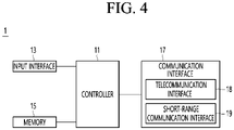
- Fig. 4 is a control block diagram of a calling device according to an embodiment of the present disclosure.
- the calling device 1 may include a controller 11, an input interface 13, a memory 15, and a communication interface 17, and the communication interface 17 may include a telecommunication interface 18 and a short-range communication interface 19.
- the controller 11 may control the overall operation of the calling device 1.
- the controller 11 may control each of the input interface 13, the memory 15, and the communication interface 18.
- the input interface 13 may receive a user input.
- the input interface 13 may be implemented as a physical key button or a touch screen capable of receiving a touch input.
- the input interface 13 may include a microphone (not illustrated) and may receive a user input through the microphone (not illustrated).
- the input interface 13 may be of various types.
- the input interface 13 may receive a control command for another electronic device.
- the memory 15 may store various information related to the operation of the calling device 1.
- the memory 15 may store information on other electronic devices.
- the memory 15 may store information on other electronic devices received from the relay server 3.
- the communication interface 17 may perform wireless communication with at least one of the target device 2, the relay server 3, and the hub 4.
- the communication interface 17 may include a telecommunication interface 18 and a short-range communication interface 19.
- the telecommunication interface 18 may be a module that communicates with an electronic device located relatively far away.
- the telecommunication interface 18 may communicate with another electronic device through mobile telecommunication, but the type of communication technology is merely exemplary and is not limited thereto.
- the short-range communication interface 19 may be a module that performs communication with an electronic device located relatively close.
- the short-range communication interface 19 may communicate with another electronic device through Bluetooth, wireless local area network (LAN), near field communication (NFC), or the like but the type of communication technology is merely exemplary and is not limited thereto.
- LAN wireless local area network
- NFC near field communication
- the telecommunication interface 18 may communicate with the relay server 3, and the short-range communication interface 19 may communicate with the target device 2 directly or communicate with the target device 2 through the hub 4.
- the communication interface 17 illustrated in Fig. 4 is divided into a telecommunication interface 18 and a short-range communication interface 19, but this is only divided for convenience of description, and it is appropriate that the present invention is not limited thereto.
- Fig. 5 is a ladder diagram illustrating an operation method of a calling device according to an embodiment of the present disclosure.
- the calling device 1 may receive a control command for the target device (S11).
- the electronic device may receive a control command for another electronic device through the input interface 13, the electronic device receiving the control command may be the calling device 1, and another electronic device that is the target of the control command may be the target device 2.
- the calling device 1 may obtain whether the device information for the target device 2 is stored (S13).
- the electronic device may obtain whether device information on another electronic device, which is the target of the control command, is stored in the memory 15.
- the relay server 3 may periodically transmit device information on each of the at least one electronic device interlocked through the relay server 3 to the electronic device interlocked to the relay server 3. Accordingly, the electronic device may receive device information on another electronic device through the relay server 3 and store the received device information on another electronic device in the memory 15.
- the relay server 3 periodically transmits device information on the interlocked electronic device, and when the electronic device updates device information on the interlocked electronic device through the relay server 3, there is an advantage that another electronic device can be controlled through the wireless LAN without through the relay server 3.
- the electronic device when the electronic device is in a power-off state, device information on other electronic devices may not be received from the relay server 3. Accordingly, if the electronic device is in a power-off state when the relay server 3 transmits information on the newly interlocked electronic device, the electronic device does not receive information on the other newly interlocked electronic device, and the memory 15 may not be able to store information on other newly interlocked electronic devices.
- the calling device 1 receives the control command for the target device 2, it is possible to obtain whether the device information on the target device 2 is stored.
- the calling device 1 may request device information to the relay server 3 (S15) and receive the device information on the target device 2 from the relay server 3 (S17).
- the relay server 3 When the relay server 3 receives a request for device information on the target device 2 from the calling device 1, the relay server may obtain device information on the target device 2 and transmit device information on the target device 2 to the calling device 1.
- the calling device 1 may obtain device information on the target device 2 from the relay server 3 or the memory 15 (S19).
- the device information may include at least one of a device type, a physical address of the device, and a command set.
- the electronic device may receive device information on another electronic device in JSON format.
- the following is an example of device information on another electronic device of the JSON standard received from the relay server 3 by the electronic device.
- the calling device 1 After the calling device 1 obtains the device information on the target device 2, based on the device information, the calling device 1 may obtain whether the target device 2 is connected to the same network as the calling device 1 (S21).
- the calling device 1 may determine whether the target device 2 is connected to the same network as the calling device 1 based on the device information of the target device 2.
- Fig. 6 is a flowchart illustrating a method of determining whether an electronic device is connected to the same network as another electronic device according to an embodiment of the present disclosure.
- Fig. 6 may be a flowchart embodying step S21 of Fig. 5 .
- the calling device 1 may obtain a physical address from the device information of the target device 2 (S101).
- the physical address may be a Media Access Control Address (MAC address).
- MAC address Media Access Control Address
- the calling device 1 may obtain a logical address by using the physical address (S103).
- the logical address may be an IP address.
- the calling device 1 may obtain the IP address of the target device 2 from the physical address of the target device 2 through Reverse Address Resolution Protocol (RARP).
- RARP Reverse Address Resolution Protocol
- the calling device 1 may compare the network address of the calling device 1 with the network address of the target device 2 (S105).
- the IP address may include a network address and a host address, the network address may be used to identify a network to which the electronic device belongs, and the host address may be used to identify the electronic device within the corresponding network.
- the calling device 1 can determine whether the calling device 1 and the target device 2 belong to the same network by comparing the network address of the calling device 1 with the network address of the target device 2.
- the calling device 1 may determine that the calling device 1 and the target device 2 are connected to the same network (S109).
- the calling device 1 may determine that the calling device 1 and the person 2 are connected to different networks.
- the calling device 1 can control the target device 2 according to the control command through the wireless LAN if the target device 2 is connected to the same network as the calling device 1 (S29).
- the calling device 1 can directly control the target device 2 using Transmission Control Protocol/Internet Protocol (TCP/IP) communication.
- TCP/IP Transmission Control Protocol/Internet Protocol
- the calling device 1 can control the target device 2 by wireless LAN communication.
- the calling device 1 can control the target device 2 by establishing the target device and a packet as in the example below.
- the calling device 1 may establish the target device 2 based on at least one of an IP address and a logical address and may establish a packet based on device information (for example, a set of commands).
- the calling device 1 requests the relay server 3 to control the target device 2 according to the control command (S25), and the relay server (3) may control the target device 2 according to the control command at the request of the calling device 1 (S27).
- the calling device 1 can control the target device 2 through the relay server 3.
- the calling device 1 when the calling device 1 receives a control command for the target device 2, according to whether the calling device is connected to the same network as the target device 2, by controlling the target device 2 using TCP/IP communication or controlling the target device 2 through the relay server 3, there is an advantage in that the delay problem felt by the user is minimized and remote control is possible at the same time.
- the calling device 1 and the target device 2 exist in different spaces, since it is difficult for the user to know the control delay, it may be sufficient for the calling device 1 to control the target device 2 through the relay server 3.
- control delay may be increased due to the operation for determining whether the calling device 1 and the target device 2 are connected to the same network.
- the electronic device when receiving a control command for another electronic device, the electronic device may obtain whether to execute the adaptive control function based on the current location.
- the adaptive control function refers to a function of selecting and controlling a method for the electronic device to control another electronic device according to a network configuration state.
- the electronic device when receiving a control command for another electronic device, the electronic device controls the target device 2 through the relay server 3, and in a case where the adaptive control function is executed, according to whether the electronic device is connected to the same network as the target device 2, the target device 2 can be controlled through TCP/IP communication or through the relay server 3.
- the target device 2 can be controlled through TCP/IP communication or through the relay server 3.
- Fig. 7 is a ladder diagram illustrating an operation method of a calling device according to another embodiment of the present disclosure.
- the calling device 1 may receive a control command for the target device (S11).
- the calling device 1 When the calling device 1 receives the control command for the target device, the calling device can obtain whether to execute the adaptive control function based on the current location (S201).
- the calling device 1 may execute the adaptive control function.
- the calling device 1 may not execute the adaptive control function if the current location does not correspond to a preset location.
- the calling device 1 can execute the adaptive control function only at a location set in advance by the user, and accordingly, there is an advantage in that the corresponding operation can be blocked at a location where the operation of determining whether the calling device is installed on the same network as the target device 2 is unnecessary.
- the calling device 1 may not execute the adaptive control function when the current location is a preset location and may execute the adaptive control function if the current location does not correspond to the preset location.
- the calling device 1 when the calling device 1 receives a control command for another electronic device, the calling device 1 can calculate a location with the nearest access point (AP) and execute an adaptive control function when the location with the AP is equal to or less than a preset distance.
- the calling device 1 may calculate a location with the nearest access point (AP), and when the location with the AP exceeds a preset distance, the adaptive control function may not be executed.
- the calling device 1 when the calling device 1 is located far from the access point (AP), the calling device 1 predicts that the distance from the target device 2 is also long and does not execute the adaptive control function, and thus there is an advantage in that it is possible to omit unnecessary operation of determining whether the target device 2 is installed on the same network.
- the calling device 1 since the calling device 1 determines whether to execute the adaptive control function based on the distance from the AP, there is an advantage that a GPS module or the like is unnecessary.
- the calling device 1 If the calling device 1 does not execute the adaptive control function, the calling device 1 transmits a signal requesting control of the target device 2 according to the control command to the relay server 3, and the relay server 3 can control the target device 2 according to the control command by the received signal from the calling device 1 (S207).
- the calling device 1 determines whether device information for the target device 2 is stored (S13), and can request device information to the relay server 3 according to the determination result (S15) or obtain device information for the target device 2 (S19).
- the calling device 1 obtains device information for the target device 2 (S19), and based on the device information, obtains whether the target device 2 is connected to the same network as the calling device 1 (S21), and according to whether the target device 2 is connected to the same network as the calling device 1, the target device 2 can transmit a signal to request that other electronic devices be controlled according to the control command through the telecommunication interface to the relay server 3 or can control another electronic device according to control commands using TCP/IP communication through the short-range communication interface.
- steps S13 to S29 are the same as described with reference to Figs. 5 and 6 , the overlapping description will be omitted.
- the electronic device performs an operation of determining whether the calling device 1 and the target person 2 are connected to the same network only when necessary, thereby reducing unnecessary costs.
Landscapes
- Engineering & Computer Science (AREA)
- Computer Networks & Wireless Communication (AREA)
- Signal Processing (AREA)
- Automation & Control Theory (AREA)
- Theoretical Computer Science (AREA)
- General Physics & Mathematics (AREA)
- General Engineering & Computer Science (AREA)
- Physics & Mathematics (AREA)
- Multimedia (AREA)
- Human Computer Interaction (AREA)
- Computing Systems (AREA)
- Selective Calling Equipment (AREA)
- Telephonic Communication Services (AREA)
Abstract
Description
- The present disclosure relates to an electronic device, and more particularly, to an electronic device for controlling another electronic device.
- The Internet of Things (loT) refers to intelligent technologies and services in which devices connected to the Internet communicate information with each other without human intervention.
- As a method of controlling devices through the existing loT, a method using a relay server and a short-range wireless communication method (BT, RF, Zigbee, or the like) are representative.
- According to the method using the relay server, unlike the short-range wireless communication method, there is an advantage in usability in that remote control is possible, but an issue in which the speed is not guaranteed may occur according to the network environment. In particular, when a user controls an electronic device through a relay server from a remote location, the speed problem may not be an issue because it is difficult to actually check the operation of the device, but the speed problem can be easily felt when a user controls an electronic device through a relay server in the same space.
- An object of the present disclosure is to provide an electronic device that efficiently configures a network for controlling another electronic device.
- An object of the present disclosure is to provide an electronic device that automatically configures a network without a user's separate input.
- An electronic device according to an embodiment of present disclosure comprises a communication interface, an input interface configured to receive a control command for another electronic device, and a controller configured to control another electronic device in a different manner according to whether connected to the same network as another electronic device.
- The controller is configured to control another electronic device through the LAN according to the control command if connected to the same network as another electronic device.
- The controller is configured to transmit a signal to request that another electronic device be controlled according to the control command to the relay server if not connected to the same network as another electronic device.
- The controller is configured to obtain whether connected to the same network as another electronic device.
- The controller is configured to obtain whether connected to the same network as another electronic device based on device information on another electronic device.
- The controller is configured to obtain a physical address from device information on another electronic device, to obtain a logical address based on the physical address, and determine whether connected to the same network as another electronic device based on the logical address.
- The electronic device further comprises a memory configured to store device information on at least one electronic device.
- The controller is configured to obtain whether device information on another electronic device according to the control command is stored in the memory and to obtain whether connected to the same network as another electric device based on the information stored in the memory if device information on another electronic device is stored in the memory.
- The controller is configured to obtain whether device information on another electronic device according to the control command is stored in the memory, and to receive device information on another electronic device by the relay server if device information on another electronic device is not stored in the memory.
- The controller is configured to obtain whether to execute the adaptive control function based on the current location when receiving the control command.
- The controller is configured to obtain whether another electronic device is connected to the same network when executing the adaptive control function and to control another electronic device in a different manner according to whether connected to the same network.
- The controller is configured to transmit a signal to request that another electronic device be controlled according to the control command to the relay server when the adaptive control function is not executed.
- The controller is configured to execute the adaptive control function when the current location is a preset location.
- The controller is configured to calculate a location with the nearest access point (AP) and to execute the adaptive control function when the location with the AP is less than or equal to a preset distance.
- The communication interface includes a telecommunication interface and a short-range communication interface, and the controller is configured to transmit a signal to request that another electronic device be controlled according to the control command to the relay server through the telecommunication interface according to whether connected to the same network as another electronic device or to control another electronic device using TCP/IP communication through the short-range communication interface according to the control command.
- According to the present disclosure, when an electronic device controls another electronic device, by differently selecting a control method according to a network configuration state, it is possible to provide usability of remotely controlling another electronic device or to minimize a delay problem through short-range control.
- In addition, by automatically selecting a method for the electronic device to control another electronic device, it is possible to provide convenience to the user who does not require a separate input.
- In addition, by periodically receiving and storing device information of another electronic device from the relay server, the electronic device may control another electronic device through short-range communication.
-
-
Fig. 1 is a diagram illustrating a method for an electronic device to control another electronic device through a relay server according to an embodiment of the present disclosure. -
Fig. 2 is a diagram illustrating a method for an electronic device to control another electronic device through a local network according to an embodiment of the present disclosure. -
Fig. 3 is a diagram illustrating a method for an electronic device according to an embodiment of the present disclosure to control an electronic device according to a network configuration state. -
Fig. 4 is a control block diagram of a calling device according to an embodiment of the present disclosure. -
Fig. 5 is a ladder diagram illustrating an operation method of a calling device according to an embodiment of the present disclosure. -
Fig. 6 is a flowchart illustrating a method of determining whether an electronic device is connected to the same network as another electronic device according to an embodiment of the present disclosure. -
Fig. 7 is a ladder diagram illustrating an operation method of a calling device according to another embodiment of the present disclosure. - Hereinafter, the embodiments disclosed herein will be described in detail with reference to the accompanying drawings, and the same or similar elements are designated with the same numeral references regardless of the numerals in the drawings and their redundant description will be omitted.
- The suffixes "module" and "unit or portion" for components used in the following description are merely provided only for facilitation of preparing this specification, and thus they are not granted a specific meaning or function.
- In addition, when it is determined that the detailed description of the related known technology may obscure the gist of embodiments disclosed herein in describing the embodiments, a detailed description thereof will be omitted. Further, the accompanying drawings are intended to facilitate understanding of the embodiments disclosed herein, and the technical spirit disclosed herein are not limited by the accompanying drawings. Therefore, the present disclosure should be construed as including all the changes, equivalents, and substitutions included in the spirit and scope of the present disclosure.
- As used herein, singular forms may include plural forms as well unless the context clearly indicates otherwise.
- It will be further understood that the terms "comprises," "comprising," "having," "having," "includes," "including" and/or variations thereof, when used in this specification, specify the presence of stated features, integers, steps, operations, elements, and/or components, but do not preclude the presence or addition of one or more other features, integers, steps, operations, elements, components, and/or groups thereof.
- Hereinafter, the electronic device may include any electronic device capable of wireless communication. For example, if the electronic device is a device capable of wireless communication, the electronic device may include not only mobile phones but also home appliances such as TVs, air conditioners, and lighting devices.
- In the present disclosure, "a calling device" refers to an electronic device that receives a control command for controlling another electronic device, and "a target device" refers to an electronic device controlled by another electronic device. In other words, "the calling device" may be a subject that controls "the target device", and "the target device" may be a target controlled by "the calling device".
- For example, the user may input a control command to "the calling device" to control "the target device".
-
Fig. 1 is a diagram illustrating a method for an electronic device to control another electronic device through a relay server according to an embodiment of the present disclosure. - The
calling device 1 may receive a control command for another electronic device. In other words, thecalling device 1 may receive a control command for thetarget device 2, which is another electronic device. - For example, the
calling device 1 is a TV, and the TV may receive a control command such as "turn on the air conditioner". In this case, the TV may transmit a signal requesting that the power of the air conditioner, which is thetarget device 2, be controlled to be turned on to therelay server 3. Therelay server 3 may control the power of the air conditioner, which is thetarget device 2, to be turned on based on the request signal received from the TV. - In this way, when the
calling device 1 controls thetarget device 2 through therelay server 3, thecalling device 1 can control thetarget device 2 even if thetarget device 2 is located far from thecalling device 1. On the other hand, since thecalling device 1 has to go through therelay server 3 to control thetarget device 2, the network cost is high, and the speed may be greatly affected by the location and status of therelay server 2, or the like. In particular, since thecalling device 1 controls thetarget device 2 through therelay server 3, the time required for thecalling device 1 to operate according to the control command after thecalling device 1 receives the control command may be relatively long. -
Fig. 2 is a diagram illustrating a method for an electronic device to control another electronic device through a local network according to an embodiment of the present disclosure. - The
calling device 1 may receive a control command for another electronic device. In other words, thecalling device 1 may receive a control command for thetarget device 2, which is another electronic device. - For example, the
calling device 1 is a smartphone, and the smartphone may receive a control command such as "turn on the lighting". In this case, the smartphone may control the power of the lighting, which is thetarget device 2, to be turned on through thehub 4, and at this time, thehub 4 is a device for connecting at least one lighting to a Local Area Network (LAN), and the smartphone and thehub 4 may be connected to the same network. Alternatively, the callingdevice 1 such as a smartphone may directly control thetarget device 2 such as lighting through short-range communication. - As such, when the calling
device 1 controls thetarget device 2 through thehub 4 or through short-range wireless communication, the network cost is low and the device can be controlled at a relatively high speed. On the other hand, since the callingdevice 1 and thetarget person 2 or thecalling device 1 and thehub 4 must exist in the same network, there is a disadvantage of poor usability. - When the electronic device controls another electronic device through only one of the method illustrated in
Fig. 1 and the method illustrated inFig. 2 , there are problems that the electronic device with improved usability may have a slow control speed of other electronic devices and the electronic device with improved speed are difficult to remotely control another electronic device. - Accordingly, the electronic device according to an embodiment of the present disclosure can increase usability and speed by adaptively controlling another electronic device according to a network configuration state.
-
Fig. 3 is a diagram illustrating a method for an electronic device according to an embodiment of the present disclosure to control an electronic device according to a network configuration state. - The calling
device 1 may receive a control command for another electronic device. In other words, the callingdevice 1 may receive a control command for thetarget device 2, which is another electronic device. - The calling
device 1 may check the network upon receiving the control command. Specifically, upon receiving the control command, the callingdevice 1 may perform a network check to obtain whether the calling device is connected to the same network as thetarget device 2 corresponding to the control command. - If the
calling device 1 is not connected to the same network as thetarget device 2, the callingdevice 1 controls the target device through therelay server 3, and if thecalling device 1 is connected to the same network as thetarget device 2, it is possible to control thetarget device 2 through thehub 4. In other words, if thecalling device 1 is not connected to the same network as thetarget device 2, the callingdevice 1 transmits a request signal to therelay server 3 so that thetarget device 2 is controlled according to the control command, and thecalling device 1 can control thetarget device 2 according to a control command through thehub 4 if thecalling device 1 is connected to the same network as thetarget device 2. -
Fig. 4 is a control block diagram of a calling device according to an embodiment of the present disclosure. - The calling
device 1 may include acontroller 11, aninput interface 13, amemory 15, and acommunication interface 17, and thecommunication interface 17 may include atelecommunication interface 18 and a short-range communication interface 19. - The
controller 11 may control the overall operation of thecalling device 1. Thecontroller 11 may control each of theinput interface 13, thememory 15, and thecommunication interface 18. - The
input interface 13 may receive a user input. Theinput interface 13 may be implemented as a physical key button or a touch screen capable of receiving a touch input. Alternatively, theinput interface 13 may include a microphone (not illustrated) and may receive a user input through the microphone (not illustrated). In other words, theinput interface 13 may be of various types. - The
input interface 13 may receive a control command for another electronic device. - The
memory 15 may store various information related to the operation of thecalling device 1. - The
memory 15 may store information on other electronic devices. For example, thememory 15 may store information on other electronic devices received from therelay server 3. - The
communication interface 17 may perform wireless communication with at least one of thetarget device 2, therelay server 3, and thehub 4. - The
communication interface 17 may include atelecommunication interface 18 and a short-range communication interface 19. - The
telecommunication interface 18 may be a module that communicates with an electronic device located relatively far away. For example, thetelecommunication interface 18 may communicate with another electronic device through mobile telecommunication, but the type of communication technology is merely exemplary and is not limited thereto. - The short-
range communication interface 19 may be a module that performs communication with an electronic device located relatively close. For example, the short-range communication interface 19 may communicate with another electronic device through Bluetooth, wireless local area network (LAN), near field communication (NFC), or the like but the type of communication technology is merely exemplary and is not limited thereto. - The
telecommunication interface 18 may communicate with therelay server 3, and the short-range communication interface 19 may communicate with thetarget device 2 directly or communicate with thetarget device 2 through thehub 4. - The
communication interface 17 illustrated inFig. 4 is divided into atelecommunication interface 18 and a short-range communication interface 19, but this is only divided for convenience of description, and it is appropriate that the present invention is not limited thereto. -
Fig. 5 is a ladder diagram illustrating an operation method of a calling device according to an embodiment of the present disclosure. - The calling
device 1 may receive a control command for the target device (S11). - The electronic device may receive a control command for another electronic device through the
input interface 13, the electronic device receiving the control command may be the callingdevice 1, and another electronic device that is the target of the control command may be thetarget device 2. - The calling
device 1 may obtain whether the device information for thetarget device 2 is stored (S13). - When the electronic device receives the control command for another electronic device, the electronic device may obtain whether device information on another electronic device, which is the target of the control command, is stored in the
memory 15. - The
relay server 3 may periodically transmit device information on each of the at least one electronic device interlocked through therelay server 3 to the electronic device interlocked to therelay server 3. Accordingly, the electronic device may receive device information on another electronic device through therelay server 3 and store the received device information on another electronic device in thememory 15. - As described above, the
relay server 3 periodically transmits device information on the interlocked electronic device, and when the electronic device updates device information on the interlocked electronic device through therelay server 3, there is an advantage that another electronic device can be controlled through the wireless LAN without through therelay server 3. - Meanwhile, when the electronic device is in a power-off state, device information on other electronic devices may not be received from the
relay server 3. Accordingly, if the electronic device is in a power-off state when therelay server 3 transmits information on the newly interlocked electronic device, the electronic device does not receive information on the other newly interlocked electronic device, and thememory 15 may not be able to store information on other newly interlocked electronic devices. - Accordingly, when the calling
device 1 receives the control command for thetarget device 2, it is possible to obtain whether the device information on thetarget device 2 is stored. - If the device information on the
target device 2 is not stored, the callingdevice 1 may request device information to the relay server 3 (S15) and receive the device information on thetarget device 2 from the relay server 3 (S17). - When the
relay server 3 receives a request for device information on thetarget device 2 from the callingdevice 1, the relay server may obtain device information on thetarget device 2 and transmit device information on thetarget device 2 to thecalling device 1. - In other words, the calling
device 1 may obtain device information on thetarget device 2 from therelay server 3 or the memory 15 (S19). - The device information may include at least one of a device type, a physical address of the device, and a command set.
- The electronic device may receive device information on another electronic device in JSON format. The following is an example of device information on another electronic device of the JSON standard received from the
relay server 3 by the electronic device.
        {
        "deviceType" : "airpurifier"
        "MAC" : "11:11:11:11:11:11"
        "commandList" : {
           "start" : "airpurifier_on"
           "stop" : "airpurifier_off" }
        }
        target: logicallp / MAC
        packet: command : airpurifier_on
Claims (15)
- An electronic device comprising:a communication interface;an input interface configured to receive a control command for another electronic device; anda controller configured to control another electronic device in a different manner according to whether connected to the same network as another electronic device.
- The electronic device of claim 1,
wherein the controller is configured to control another electronic device through the LAN according to the control command if connected to the same network as another electronic device. - The electronic device of claim 1,
wherein the controller is configured to transmit a signal to request that another electronic device be controlled according to the control command to the relay server if not connected to the same network as another electronic device. - The electronic device of claim 1,
wherein the controller is configured to obtain whether connected to the same network as another electronic device. - The electronic device of claim 4,
wherein the controller is configured to obtain whether connected to the same network as another electronic device based on device information on another electronic device. - The electronic device of claim 5,
wherein the controller is configured to obtain a physical address from device information on another electronic device, to obtain a logical address based on the physical address, and determine whether connected to the same network as another electronic device based on the logical address. - The electronic device of claim 5, further comprising:
a memory configured to store device information on at least one electronic device. - The electronic device of claim 7,
wherein the controller is configured to obtain whether device information on another electronic device according to the control command is stored in the memory and to obtain whether connected to the same network as another electric device based on the information stored in the memory if device information on another electronic device is stored in the memory. - The electronic device of claim 7,
wherein the controller is configured to obtain whether device information on another electronic device according to the control command is stored in the memory, and to receive device information on another electronic device by the relay server if device information on another electronic device is not stored in the memory. - The electronic device of claim 1,
wherein the controller is configured to obtain whether to execute the adaptive control function based on the current location when receiving the control command. - The electronic device of claim 10,
wherein the controller is configured to obtain whether another electronic device is connected to the same network when executing the adaptive control function and to control another electronic device in a different manner according to whether connected to the same network. - The electronic device of claim 10,
wherein the controller is configured to transmit a signal to request that another electronic device be controlled according to the control command to the relay server when the adaptive control function is not executed. - The electronic device of claim 10,
wherein the controller is configured to execute the adaptive control function when the current location is a preset location. - The electronic device of claim 10,
wherein the controller is configured to calculate a location with the nearest access point (AP) and to execute the adaptive control function when the location with the AP is less than or equal to a preset distance. - The electronic device of claim 1,wherein the communication interface includes a telecommunication interface and a short-range communication interface, andwherein the controller is configured to transmit a signal to request that another electronic device be controlled according to the control command to the relay server through the telecommunication interface according to whether connected to the same network as another electronic device or to control another electronic device using TCP/IP communication through the short-range communication interface according to the control command.
Applications Claiming Priority (1)
| Application Number | Priority Date | Filing Date | Title |
|---|---|---|---|
| PCT/KR2019/015869 WO2021100895A1 (en) | 2019-11-19 | 2019-11-19 | Electronic device |
Publications (4)
| Publication Number | Publication Date |
|---|---|
| EP4064615A1 true EP4064615A1 (en) | 2022-09-28 |
| EP4064615A4 EP4064615A4 (en) | 2023-08-16 |
| EP4064615B1 EP4064615B1 (en) | 2025-05-21 |
| EP4064615C0 EP4064615C0 (en) | 2025-05-21 |
Family
ID=75980508
Family Applications (1)
| Application Number | Title | Priority Date | Filing Date |
|---|---|---|---|
| EP19953342.3A Active EP4064615B1 (en) | 2019-11-19 | 2019-11-19 | Electronic device |
Country Status (3)
| Country | Link |
|---|---|
| US (1) | US12261717B2 (en) |
| EP (1) | EP4064615B1 (en) |
| WO (1) | WO2021100895A1 (en) |
Family Cites Families (12)
| Publication number | Priority date | Publication date | Assignee | Title |
|---|---|---|---|---|
| JP2003087293A (en) * | 2001-09-11 | 2003-03-20 | Hitachi Ltd | Network device, network control device, and control method for network device |
| US8078787B2 (en) * | 2007-06-22 | 2011-12-13 | Apple Inc. | Communication between a host device and an accessory via an intermediate device |
| WO2013024922A1 (en) * | 2011-08-17 | 2013-02-21 | 엘지전자 주식회사 | Electronic device and method for operating same |
| JP5306510B1 (en) * | 2012-04-23 | 2013-10-02 | 株式会社東芝 | Electronic device, wireless connection control method, wireless connection control program |
| KR102254856B1 (en) * | 2014-09-23 | 2021-05-21 | 엘지전자 주식회사 | Computer system |
| KR101628534B1 (en) * | 2014-11-19 | 2016-06-08 | 닉스테크 주식회사 | VIRTUAL 802.1x METHOD AND DEVICE FOR NETWORK ACCESS CONTROL |
| WO2017023625A1 (en) * | 2015-07-31 | 2017-02-09 | Apple Inc. | Delegation of trigger execution in an automated environment |
| KR102331536B1 (en) * | 2015-12-18 | 2021-11-26 | 한화테크윈 주식회사 | Network device and operation method thereof |
| KR102405694B1 (en) * | 2015-12-23 | 2022-06-07 | 삼성전자주식회사 | Method of operating electric device and relay device and method of operating the same |
| US10270610B2 (en) * | 2016-06-12 | 2019-04-23 | Apple Inc. | Selection of a coordinator device for an automated environment |
| KR102390979B1 (en) * | 2017-10-17 | 2022-04-26 | 삼성전자주식회사 | Electronic Device Capable of controlling IoT device to corresponding to the state of External Electronic Device and Electronic Device Operating Method |
| KR102898271B1 (en) * | 2019-11-12 | 2025-12-12 | 삼성전자주식회사 | Electronic device and method for controlling electronic device |
-
2019
- 2019-11-19 US US17/778,362 patent/US12261717B2/en active Active
- 2019-11-19 EP EP19953342.3A patent/EP4064615B1/en active Active
- 2019-11-19 WO PCT/KR2019/015869 patent/WO2021100895A1/en not_active Ceased
Also Published As
| Publication number | Publication date |
|---|---|
| US12261717B2 (en) | 2025-03-25 |
| EP4064615B1 (en) | 2025-05-21 |
| EP4064615C0 (en) | 2025-05-21 |
| WO2021100895A1 (en) | 2021-05-27 |
| US20230006862A1 (en) | 2023-01-05 |
| EP4064615A4 (en) | 2023-08-16 |
Similar Documents
| Publication | Publication Date | Title |
|---|---|---|
| EP3492830B1 (en) | Multi air conditioner | |
| CN201749342U (en) | Control device and control system | |
| US7826395B2 (en) | Communication system using zigbee and method of controlling the same | |
| EP2879332A1 (en) | Communication apparatus, communication relay apparatus and communication system | |
| CN103512159A (en) | Air conditioner and air conditioner control system | |
| KR102125799B1 (en) | IoT terminal remote controller based IoT control system and control method | |
| CN104483951B (en) | A kind of method, apparatus and terminal for controlling intelligent home device | |
| CN103685733A (en) | Remote control method and terminal | |
| US10693714B2 (en) | Communication method for Wi-Fi internet of things equipment and Wi-Fi internet of things system | |
| EP3800904B1 (en) | Device control method and device | |
| CN108234562B (en) | Equipment control method, control equipment and controlled equipment | |
| CN111161522A (en) | Method for processing remote control data, storage medium, computer device and remote control system | |
| CN101567823B (en) | Communication system using ZigBee and method for controlling same | |
| EP2975855A1 (en) | Operation terminal control system | |
| CN104916118A (en) | Method and device for realizing infrared remote control | |
| CN106610090B (en) | Temperature control method, device and system | |
| CN202630316U (en) | Air conditioner and air conditioner control system | |
| EP4064615A1 (en) | Electronic device | |
| KR102005409B1 (en) | FOTA SYSTEM USING FSK MODE IN LoRa IoT | |
| JP2022009020A (en) | Home appliance remote control methods, programs, and systems | |
| JP2014031957A (en) | Air conditioner | |
| US20240212482A1 (en) | Systems and methods for remotely activating a wireless radio | |
| KR101290727B1 (en) | Apparatus to update S/W of system air conditioner and method thereof | |
| KR100873905B1 (en) | Communication system using Zigbee and its control method | |
| JP2017022556A (en) | Communication device and communication method |
Legal Events
| Date | Code | Title | Description |
|---|---|---|---|
| STAA | Information on the status of an ep patent application or granted ep patent |
Free format text: STATUS: THE INTERNATIONAL PUBLICATION HAS BEEN MADE |
|
| PUAI | Public reference made under article 153(3) epc to a published international application that has entered the european phase |
Free format text: ORIGINAL CODE: 0009012 |
|
| STAA | Information on the status of an ep patent application or granted ep patent |
Free format text: STATUS: REQUEST FOR EXAMINATION WAS MADE |
|
| 17P | Request for examination filed |
Effective date: 20220519 |
|
| AK | Designated contracting states |
Kind code of ref document: A1 Designated state(s): AL AT BE BG CH CY CZ DE DK EE ES FI FR GB GR HR HU IE IS IT LI LT LU LV MC MK MT NL NO PL PT RO RS SE SI SK SM TR |
|
| DAV | Request for validation of the european patent (deleted) | ||
| DAX | Request for extension of the european patent (deleted) | ||
| A4 | Supplementary search report drawn up and despatched |
Effective date: 20230717 |
|
| RIC1 | Information provided on ipc code assigned before grant |
Ipc: H04W 84/18 20090101ALI20230711BHEP Ipc: H04L 41/08 20220101ALI20230711BHEP Ipc: H04L 41/0806 20220101ALI20230711BHEP Ipc: G06F 13/38 20060101ALI20230711BHEP Ipc: H04W 76/14 20180101ALI20230711BHEP Ipc: H04L 12/28 20060101ALI20230711BHEP Ipc: H04W 88/08 20090101ALI20230711BHEP Ipc: H04L 12/66 20060101ALI20230711BHEP Ipc: H04L 12/12 20060101AFI20230711BHEP |
|
| STAA | Information on the status of an ep patent application or granted ep patent |
Free format text: STATUS: EXAMINATION IS IN PROGRESS |
|
| 17Q | First examination report despatched |
Effective date: 20240725 |
|
| GRAP | Despatch of communication of intention to grant a patent |
Free format text: ORIGINAL CODE: EPIDOSNIGR1 |
|
| STAA | Information on the status of an ep patent application or granted ep patent |
Free format text: STATUS: GRANT OF PATENT IS INTENDED |
|
| INTG | Intention to grant announced |
Effective date: 20241218 |
|
| GRAS | Grant fee paid |
Free format text: ORIGINAL CODE: EPIDOSNIGR3 |
|
| GRAA | (expected) grant |
Free format text: ORIGINAL CODE: 0009210 |
|
| STAA | Information on the status of an ep patent application or granted ep patent |
Free format text: STATUS: THE PATENT HAS BEEN GRANTED |
|
| AK | Designated contracting states |
Kind code of ref document: B1 Designated state(s): AL AT BE BG CH CY CZ DE DK EE ES FI FR GB GR HR HU IE IS IT LI LT LU LV MC MK MT NL NO PL PT RO RS SE SI SK SM TR |
|
| REG | Reference to a national code |
Ref country code: GB Ref legal event code: FG4D |
|
| REG | Reference to a national code |
Ref country code: CH Ref legal event code: EP |
|
| REG | Reference to a national code |
Ref country code: DE Ref legal event code: R096 Ref document number: 602019070441 Country of ref document: DE |
|
| REG | Reference to a national code |
Ref country code: IE Ref legal event code: FG4D |
|
| U01 | Request for unitary effect filed |
Effective date: 20250612 |
|
| U07 | Unitary effect registered |
Designated state(s): AT BE BG DE DK EE FI FR IT LT LU LV MT NL PT RO SE SI Effective date: 20250624 |
|
| PG25 | Lapsed in a contracting state [announced via postgrant information from national office to epo] |
Ref country code: ES Free format text: LAPSE BECAUSE OF FAILURE TO SUBMIT A TRANSLATION OF THE DESCRIPTION OR TO PAY THE FEE WITHIN THE PRESCRIBED TIME-LIMIT Effective date: 20250521 |
|
| PG25 | Lapsed in a contracting state [announced via postgrant information from national office to epo] |
Ref country code: NO Free format text: LAPSE BECAUSE OF FAILURE TO SUBMIT A TRANSLATION OF THE DESCRIPTION OR TO PAY THE FEE WITHIN THE PRESCRIBED TIME-LIMIT Effective date: 20250821 Ref country code: GR Free format text: LAPSE BECAUSE OF FAILURE TO SUBMIT A TRANSLATION OF THE DESCRIPTION OR TO PAY THE FEE WITHIN THE PRESCRIBED TIME-LIMIT Effective date: 20250822 |
|
| PG25 | Lapsed in a contracting state [announced via postgrant information from national office to epo] |
Ref country code: PL Free format text: LAPSE BECAUSE OF FAILURE TO SUBMIT A TRANSLATION OF THE DESCRIPTION OR TO PAY THE FEE WITHIN THE PRESCRIBED TIME-LIMIT Effective date: 20250521 |
|
| PG25 | Lapsed in a contracting state [announced via postgrant information from national office to epo] |
Ref country code: HR Free format text: LAPSE BECAUSE OF FAILURE TO SUBMIT A TRANSLATION OF THE DESCRIPTION OR TO PAY THE FEE WITHIN THE PRESCRIBED TIME-LIMIT Effective date: 20250521 |
|
| PG25 | Lapsed in a contracting state [announced via postgrant information from national office to epo] |
Ref country code: RS Free format text: LAPSE BECAUSE OF FAILURE TO SUBMIT A TRANSLATION OF THE DESCRIPTION OR TO PAY THE FEE WITHIN THE PRESCRIBED TIME-LIMIT Effective date: 20250821 |
|
| PG25 | Lapsed in a contracting state [announced via postgrant information from national office to epo] |
Ref country code: IS Free format text: LAPSE BECAUSE OF FAILURE TO SUBMIT A TRANSLATION OF THE DESCRIPTION OR TO PAY THE FEE WITHIN THE PRESCRIBED TIME-LIMIT Effective date: 20250921 |
|
| U20 | Renewal fee for the european patent with unitary effect paid |
Year of fee payment: 7 Effective date: 20251124 |
|
| PGFP | Annual fee paid to national office [announced via postgrant information from national office to epo] |
Ref country code: GB Payment date: 20251001 Year of fee payment: 7 |
|
| PG25 | Lapsed in a contracting state [announced via postgrant information from national office to epo] |
Ref country code: SM Free format text: LAPSE BECAUSE OF FAILURE TO SUBMIT A TRANSLATION OF THE DESCRIPTION OR TO PAY THE FEE WITHIN THE PRESCRIBED TIME-LIMIT Effective date: 20250521 |
|
| PG25 | Lapsed in a contracting state [announced via postgrant information from national office to epo] |
Ref country code: CZ Free format text: LAPSE BECAUSE OF FAILURE TO SUBMIT A TRANSLATION OF THE DESCRIPTION OR TO PAY THE FEE WITHIN THE PRESCRIBED TIME-LIMIT Effective date: 20250521 |
|
| PG25 | Lapsed in a contracting state [announced via postgrant information from national office to epo] |
Ref country code: SK Free format text: LAPSE BECAUSE OF FAILURE TO SUBMIT A TRANSLATION OF THE DESCRIPTION OR TO PAY THE FEE WITHIN THE PRESCRIBED TIME-LIMIT Effective date: 20250521 |
|
| PLBE | No opposition filed within time limit |
Free format text: ORIGINAL CODE: 0009261 |
|
| STAA | Information on the status of an ep patent application or granted ep patent |
Free format text: STATUS: NO OPPOSITION FILED WITHIN TIME LIMIT |
|
| REG | Reference to a national code |
Ref country code: CH Ref legal event code: L10 Free format text: ST27 STATUS EVENT CODE: U-0-0-L10-L00 (AS PROVIDED BY THE NATIONAL OFFICE) Effective date: 20260402 |
|
| 26N | No opposition filed |
Effective date: 20260224 |