EP4064488A1 - Abstandselemente für den leitungsschutz in der nähe von unkonventionellen quellen - Google Patents
Abstandselemente für den leitungsschutz in der nähe von unkonventionellen quellen Download PDFInfo
- Publication number
- EP4064488A1 EP4064488A1 EP22162845.6A EP22162845A EP4064488A1 EP 4064488 A1 EP4064488 A1 EP 4064488A1 EP 22162845 A EP22162845 A EP 22162845A EP 4064488 A1 EP4064488 A1 EP 4064488A1
- Authority
- EP
- European Patent Office
- Prior art keywords
- fault
- current
- signal
- voltage
- distance
- Prior art date
- Legal status (The legal status is an assumption and is not a legal conclusion. Google has not performed a legal analysis and makes no representation as to the accuracy of the status listed.)
- Pending
Links
- 230000002441 reversible effect Effects 0.000 claims description 58
- 230000001681 protective effect Effects 0.000 claims description 23
- 238000004891 communication Methods 0.000 claims description 13
- 230000000694 effects Effects 0.000 claims description 5
- 238000000034 method Methods 0.000 abstract description 16
- 238000005259 measurement Methods 0.000 description 17
- 238000010586 diagram Methods 0.000 description 15
- 230000010287 polarization Effects 0.000 description 10
- 238000013459 approach Methods 0.000 description 8
- 238000001514 detection method Methods 0.000 description 8
- 238000001228 spectrum Methods 0.000 description 8
- 230000000903 blocking effect Effects 0.000 description 6
- 230000001360 synchronised effect Effects 0.000 description 6
- 238000012544 monitoring process Methods 0.000 description 5
- 230000004044 response Effects 0.000 description 5
- 238000002847 impedance measurement Methods 0.000 description 4
- 230000011664 signaling Effects 0.000 description 4
- 230000009286 beneficial effect Effects 0.000 description 3
- 230000008901 benefit Effects 0.000 description 3
- 230000008859 change Effects 0.000 description 3
- 230000002411 adverse Effects 0.000 description 2
- 230000006399 behavior Effects 0.000 description 2
- 230000005540 biological transmission Effects 0.000 description 2
- 238000004364 calculation method Methods 0.000 description 2
- 230000007423 decrease Effects 0.000 description 2
- 230000006870 function Effects 0.000 description 2
- 230000006698 induction Effects 0.000 description 2
- 230000008569 process Effects 0.000 description 2
- 238000012545 processing Methods 0.000 description 2
- 244000145845 chattering Species 0.000 description 1
- 230000003247 decreasing effect Effects 0.000 description 1
- 230000003111 delayed effect Effects 0.000 description 1
- 230000001419 dependent effect Effects 0.000 description 1
- ZZUFCTLCJUWOSV-UHFFFAOYSA-N furosemide Chemical compound C1=C(Cl)C(S(=O)(=O)N)=CC(C(O)=O)=C1NCC1=CC=CO1 ZZUFCTLCJUWOSV-UHFFFAOYSA-N 0.000 description 1
- 230000001939 inductive effect Effects 0.000 description 1
- 230000002452 interceptive effect Effects 0.000 description 1
- 230000003278 mimic effect Effects 0.000 description 1
- 238000012806 monitoring device Methods 0.000 description 1
- 230000003287 optical effect Effects 0.000 description 1
- 238000005070 sampling Methods 0.000 description 1
- 238000004804 winding Methods 0.000 description 1
Images





Classifications
-
- H—ELECTRICITY
- H02—GENERATION; CONVERSION OR DISTRIBUTION OF ELECTRIC POWER
- H02H—EMERGENCY PROTECTIVE CIRCUIT ARRANGEMENTS
- H02H3/00—Emergency protective circuit arrangements for automatic disconnection directly responsive to an undesired change from normal electric working condition with or without subsequent reconnection ; integrated protection
- H02H3/40—Emergency protective circuit arrangements for automatic disconnection directly responsive to an undesired change from normal electric working condition with or without subsequent reconnection ; integrated protection responsive to ratio of voltage and current
-
- G—PHYSICS
- G01—MEASURING; TESTING
- G01R—MEASURING ELECTRIC VARIABLES; MEASURING MAGNETIC VARIABLES
- G01R31/00—Arrangements for testing electric properties; Arrangements for locating electric faults; Arrangements for electrical testing characterised by what is being tested not provided for elsewhere
- G01R31/08—Locating faults in cables, transmission lines, or networks
- G01R31/081—Locating faults in cables, transmission lines, or networks according to type of conductors
- G01R31/086—Locating faults in cables, transmission lines, or networks according to type of conductors in power transmission or distribution networks, i.e. with interconnected conductors
-
- G—PHYSICS
- G01—MEASURING; TESTING
- G01R—MEASURING ELECTRIC VARIABLES; MEASURING MAGNETIC VARIABLES
- G01R31/00—Arrangements for testing electric properties; Arrangements for locating electric faults; Arrangements for electrical testing characterised by what is being tested not provided for elsewhere
- G01R31/50—Testing of electric apparatus, lines, cables or components for short-circuits, continuity, leakage current or incorrect line connections
- G01R31/52—Testing for short-circuits, leakage current or ground faults
-
- H—ELECTRICITY
- H02—GENERATION; CONVERSION OR DISTRIBUTION OF ELECTRIC POWER
- H02H—EMERGENCY PROTECTIVE CIRCUIT ARRANGEMENTS
- H02H3/00—Emergency protective circuit arrangements for automatic disconnection directly responsive to an undesired change from normal electric working condition with or without subsequent reconnection ; integrated protection
- H02H3/08—Emergency protective circuit arrangements for automatic disconnection directly responsive to an undesired change from normal electric working condition with or without subsequent reconnection ; integrated protection responsive to excess current
- H02H3/081—Emergency protective circuit arrangements for automatic disconnection directly responsive to an undesired change from normal electric working condition with or without subsequent reconnection ; integrated protection responsive to excess current and depending on the direction
-
- H—ELECTRICITY
- H02—GENERATION; CONVERSION OR DISTRIBUTION OF ELECTRIC POWER
- H02H—EMERGENCY PROTECTIVE CIRCUIT ARRANGEMENTS
- H02H7/00—Emergency protective circuit arrangements specially adapted for specific types of electric machines or apparatus or for sectionalised protection of cable or line systems, and effecting automatic switching in the event of an undesired change from normal working conditions
- H02H7/26—Sectionalised protection of cable or line systems, e.g. for disconnecting a section on which a short-circuit, earth fault, or arc discharge has occured
Definitions
- This disclosure relates to distance protection of electric power delivery systems. More particularly, this disclosure relates to distance protection using apparent impedance independent of memory and cross-phase polarizing. Distance protection herein may use undervoltage elements for faulted-loop selection. Distance protection herein may include directional supervision using time-domain quantities or weak-infeed directional elements.
- Electric power delivery systems are typically monitored and protected by IEDs that obtain electrical measurements such as voltage and current from the power system and use those measurements to determine a condition of the power system. IEDs may perform a protective action (such as signaling a circuit breaker to trip) under certain determined conditions.
- IEDs may perform a protective action (such as signaling a circuit breaker to trip) under certain determined conditions.
- Traditionally electric power delivery systems include synchronous generators, sources of electric power that respond to short circuit in a universal and well-understood way. Universal short-circuit responses have become the foundation for several system protection principles such as distance elements, directional elements, and faulted-loop selection logic. Each of these are key components in traditional line protection applications.
- Unconventional sources are power sources that exhibit behavior during system faults that is considerably different than that of a synchronous generator.
- unconventional sources include several types of wind-powered induction generators as well as inverter-based sources such as photovoltaic-powered sources or newer types of wind-powered generators.
- Unconventional sources create adverse operating conditions for distance elements in traditional line protection applications.
- the frequency of fault voltages and currents that an unconventional source supplies can significantly differ from the pre-fault frequency. This frequency difference challenges memory polarization in the mho distance element logic.
- the negative-sequence current does not maintain a fixed relationship with the negative-sequence voltage at the source terminals. This unusual negative-sequence behavior can adversely affect traditional faulted-loop selection logic as well as the directional supervision in distance elements and the reactance comparator polarization in quadrilateral distance elements.
- a software module or component may include any type of computer instruction or computer executable code located within a memory device and/or transmitted as electronic signals over a system bus or wired or wireless network.
- a software module or component may, for instance, comprise one or more physical or logical blocks of computer instructions.
- Software modules or components may comprise disparate instructions stored in different locations of a memory device, which together implement the described functionality of the module. Indeed, a module or component may comprise a single instruction or many instructions, and may be distributed over several different code segments, among different programs, and across several memory devices. Some embodiments may be practiced in a distributed computing environment.
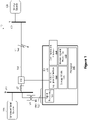
- Figure 1 illustrates a one-line diagram of an electric power delivery system 10 fed by unconventional source 156 at terminal S 152 that is local to the considered distance relay 110 and a strong source 158 at terminal T 154 that is remote to the considered distance relay.
- Transmission line 114 connects terminal S 152 with terminal T 154.
- the system may include various other lines, branches, transformers, loads, and the like, but is illustrated in simplified form for ease of discussion herein.
- line 114 may be monitored and protected using a system of IEDs that includes IED 110 and various other IEDs (not illustrated).
- the distance protection concepts described herein are implemented using power system signals from a single end of the system.
- the IED 110 provides electric power system protection such as differential protection, distance protection, overcurrent protection, and the like.
- the illustrated IED 110 includes a processor 140 for executing computer instructions, which may comprise one or more general purpose processors, special purposes processors, applicationspecific integrated circuits, programmable logic elements (e. g . , FPGAs), or the like.
- the IED 110 may further comprise non-transitory machine-readable storage media 136, which may include one or more disks, solid-state storage (e. g. , Flash memory), optical media, or the like for storing computer instructions, measurements, settings and the like.
- the storage media 136 may be packaged with the processor 140, separate from the processor 140, or there may be multiple physical storage media 136 including media packaged with the processor 140 and media 136 separate from the processor 140.
- the IED 110 may be communicatively coupled to other IEDs and/or supervisory systems either directly or using one or more communication networks via one or more communication interfaces 134.
- the IED 110 may include human-machine interface (HMI) components (not shown), such as a display, input devices, and so on.
- HMI human-machine interface
- the IED 110 may include a plurality of monitoring and protection elements, described as a monitoring and protection module 138 that may be embodied as instructions stored on computer-readable media (such as storage media 136).
- the instructions when executed on the processor 140, cause the IED to detect a fault and may also cause the IED to execute a protective action in response to the detected fault (e. g. signaling a circuit breaker to open the appropriate phases), display fault information, send messages including the fault information, and the like.
- Methods disclosed herein may generally follow the instructions stored on media for system protection.
- the monitoring and protection module 138 may include an overcurrent element, a differential element, a distance element, and the like.
- the storage media 136 may include protective action instructions to cause the IED 110 to signal a circuit breaker 102 to open via the monitored equipment interface 132 upon detection of a fault condition.
- the IED 110 may obtain electrical signals (the stimulus 122) from the power system 10 through instrument transformers (CTs, VTs, or the like).
- the stimulus 122 may be received directly via the measurement devices described above and/or indirectly via the communication interface 134 ( e . g. , from another IED or other monitoring device (not shown) in the electrical power system 10).
- the stimulus 122 may include, but is not limited to: current measurements, voltage measurements, equipment status (breaker open/closed) and the like.
- the IED includes a signal processing module 130 to receive the electric power system signals and process the signals for monitoring and protection such as distance protection.
- Line currents and voltages are sampled at a rate suitable for protection, such as in the order of kHz to MHz.
- An analog-to-digital converter (ADC) may be included to create digital representations of the incoming line current and voltage measurements.
- the output of the ADC may be used in various embodiments herein.
- the voltage and/or current signals are used to detect faults and determine a protective action.
- a monitored equipment interface 132 may be in electrical communication with monitored equipment such as circuit breaker 102. Circuit breaker 102 is configured to selectively trip (open).
- the monitored equipment interface 132 may include hardware for providing a signal to the circuit breaker 102 to open and/or close in response to a command from the IED 110.
- the monitoring and protection module 138 is configured to determine a protective action and effect the protective action on the power system by, for example, signaling the monitored equipment interface 132 to provide an open signal to the appropriate circuit breaker 102.
- the IED 110 may signal other devices (using, for example, the network, or signaling another device directly by using inputs and outputs) regarding the fault, which other devices may signal a breaker to open, thus effecting the protective action on the electric power delivery system.
- IED 110 is configured to detect faults on the electric power delivery system, determine if the fault is within a protected zone, and effect a protective action if the fault is within the protected zone. Accordingly, IEDs 110, 112 includes distance protection elements to determine a fault, determine if the fault is internal to the protected zone, and send a trip signal to circuit breaker 102.
- the distance element includes several components, including directional determination, faulted loop determination, and distance determination.
- the distance element in accordance with several embodiments herein is configured to retain integrity even when used to protect electric power systems with unconventional power sources 156.
- FIGs 2A and 2B illustrate plots of current signals ( Figure 2A ) and voltage signals ( Figure 2B ) collected during a B-phase-to-ground fault at time stamp 0ms.
- the B-phase current 204 increases slightly during less than one full cycle, before decreasing somewhat erratically.
- the A-phase current 202 and C-phase current 206 also decrease somewhat.
- the B-phase voltage 214 drops sharply upon occurrence of the fault, and the voltages on the A-phase 212 and C-phase 216 remain relatively nominal in magnitude.
- unusual current signal patterns are present when a fault is fed by an unconventional source as compared with a synchronous generator.
- Both a synchronous generator and its prime mover have a significant rotating mass.
- the large rotating mass provides high mechanical inertia for the generated electric power.
- the rotor of a synchronous generator continues to rotate at an unchanged speed for at least several hundred milliseconds before any appreciable change in speed occurs.
- This constant speed of rotation allows an IED to effectively track the phase angle of the equivalent voltage source that drives the fault current.
- This voltage phase angle in turn allows directional protection.
- This method of detecting fault current direction is especially beneficial when the IED cannot measure the phase angle of the fault voltage (when the fault voltage is low and its phase angle is unreliable). From a signal processing perspective, the operation of extrapolating the source voltage angle from pre-fault to fault conditions requires memorizing the pre-fault voltage phase angle and its rate of change (frequency), hence the label memory polarization.
- Memory polarization is widely used in mho distance elements. Its primary purpose is to make the element reliably directional with a secondary benefit of improving dependability (coverage) for resistive faults through the effect of dynamic expansion of the operating characteristic. Memory polarization of mho distance elements provides security and dependability for close-in three-phase metallic faults when the fault voltage in all phases is very low or zero and the relay cannot use it to detect the direction of the fault current.
- An unconventional source has a very low inertia (wind-powered induction generators) or no mechanical inertia at all (inverter-based sources).
- the source voltage phase angle may change considerably with respect to the pre-fault angle.
- an inverter-based source may incorrectly measure the system frequency during fault conditions. If so, the source may supply voltages and currents at a frequency that is unintentionally different from the pre-fault frequency. If a mho distance element uses the pre-fault (memory) voltage angle and extrapolates it based on the pre-fault frequency while the source operates at a different frequency than the pre-fault frequency, then the polarization gradually becomes incorrect with the passing of time.
- Incorrect memory polarization may result in a loss of security (reverse faults appear forward) or a loss of dependability (forward faults appear reverse).
- a distance element may pick up and drop out repeatedly when using an incorrect polarizing voltage. This chattering may prevent time-delayed operation in a step distance backup protection application.
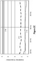
- Figure 2C illustrates traces of the apparent resistance 214 and apparent reactance 212 for the B-phase-to-ground fault of Figures 2A and 2B .
- the apparent impedance is relatively constant, and it correctly reflects the distance to the fault.
- the line impedance 216 is about 7. 4 ⁇ secondary and the fault is located at about 30 percent of the line length from the terminal. Accordingly, several embodiments herein use apparent impedance to determine a distance to the fault. Apparent impedance is used instead of traditional methods of fault distance calculation such as polarizing with memory voltage or negative-sequence current.
- Apparent impedance is calculated using the current and voltage measured at the IED.
- the apparent impedance may be calculated using phasor values. For example, dividing the measured voltage phasor by the measured current phasor yields the apparent impedance. It should be noted, however, that in typical power system protection phasors are calculated using cosine or Fourier filters. Apparent impedance calculated using phasors is, therefore, frequency dependent, and typically represents energy at around the fundamental power system frequency. As discussed and illustrated herein, during faults the voltages and currents supplied by unconventional sources can be low and distorted. The voltages and currents may have their energy spread out across a frequency spectrum instead of being concentrated at the power frequency. By using signal energy from a broader spectrum instead of from a narrow band around the power frequency, apparent impedance measurement can be improved.
- apparent impedance may be calculated from instantaneous loop voltage (v) and current (i) using parameter-fitting principles.
- the apparent resistance (R) and the apparent inductance (L) are values that - together as a pair - fit the measured voltage to the expected voltage derived from the current.
- the apparent resistance and inductance values that minimize the objective function of Equation 1 are the values used to calculate apparent impedance: ⁇ T 0 T v ⁇ R ⁇ i ⁇ L di dt 2 dt
- T 0 is the fault inception time, which may be delayed by several milliseconds to flush out the initial transients that do not reflect the R-L nature of the measurement loop
- T is the most recent time (time of the latest signal sample available in the IED).
- Equation 1 The approach illustrated in Equation 1 is the least-error squared fit of the parameters of the process (R, L) to the measurements (v, i).
- Traditional distance protection applies polarization with the voltage (mho) and the sequence currents (quadrilateral) instead of using apparent impedance.
- the distance element may intentionally take a longer time to operate to gain better accuracy of the apparent impedance measurement. For example, 40 ms into the fault, the relay uses a window that is 35 ms long in the present example.
- Equation 1 uses the signal energy contained in a wider spectrum of at least a few hundred hertz - the spectrum allowed by the low-pass filter applied to the instantaneous voltages and currents.
- the total energy contained in the spectrum is higher than the energy carried in the phasors in the narrow band around the power system frequency.
- Equation 1 does not depend on the system frequency or on the measurement of the system frequency. Accordingly, genuine changes in system frequency, or frequency measurement lag, or errors do not affect this method. Additionally, the approach is a constant inductance method, and it maintains a constant distance element reach even when the system frequency is different than nominal.
- Equation 1 may be implemented in several ways such as is described below.
- Operations 2b and 2c ensure that the voltage, current, and the current derivative all have the same group delay.
- R k D k ⁇ C k ⁇ B k ⁇ E k A k ⁇ C k ⁇ B k 2
- X k A k ⁇ E k ⁇ B k ⁇ D k A k ⁇ C k ⁇ B k 2
- a microprocessor-based IED may implement the time-domain wide-spectrum apparent impedance calculation using the above method.
- the IED may execute equations 2a, 2b, and 2c, which are equations for simple two-tap finite impulse response filters.
- the IED may calculate the accumulated sums in Equations 5a-5e.
- the IED may then calculate the apparent impedance using Equations 4a and 4b.
- the IED may verify if the apparent impedance is inside or outside of the operating characteristic, such as in Figures 3A, 3B , and 5 (discussed hereafter).
- the voltage (v) and current (i) inputs are instantaneous loop voltages and currents and may be calculated first from the phase instantaneous quantities according to the principles of six-loop distance protection for three-phase systems.
- the current signal (i) in Equations 2a-2c is a measured value and does not need to nor should it be filtered with the mimic (dc removal) filter.
- the time-domain wide-spectrum apparent impedance approach is especially beneficial when measuring phase-to-phase apparent impedances because of the very low phase-to-phase currents supplied by unconventional sources during phase faults (very high system impedance ratio for phase faults). It shall be understood that this invention is not limited to using the time-domain wide-spectrum apparent impedance measurement. Phasor-based apparent impedance measurement may be used as well while achieving other benefits of this embodiments described herein, except the better accuracy as it relates to weak source phenomena.
- Apparent impedance may be used to determine fault distance using distance operating characteristics such as mho operating or quadrilateral operating characteristics.
- distance operating characteristics such as mho operating or quadrilateral operating characteristics.
- use of apparent impedance instead of traditional polarization may be unreliable in detection of fault direction in certain situations. For example, for close-in bolted faults, the measured voltage is very low or zero, preventing the apparent impedance distance element from detecting the fault direction.
- the nondirectional distance element may include an offset distance characteristic.
- Such an operating characteristic may be offset in the reverse direction so that it includes the origin of the apparent impedance plane, resulting in a distance element that is dependable but is nondirectional (would operate for both close-in forward and reverse faults).
- Figures 3A and 3B illustrate offset (nondirectional) distance operating characteristics that may be used in accordance with several embodiments herein.
- Figure 3A illustrates a circular (mho) characteristic 302 that is offset in the reverse direction to include the origin of the apparent impedance (reactance-resistance) plane.
- the characteristic is defined by both forward 304 direction reach and reverse 306 direction reach.
- Figure 3B illustrates an offset (nondirectional) apparent-impedance quadrilateral operating characteristic 312 that may be used in various embodiments herein.
- the quadrilateral characteristic 312 is offset to include the origin, and covers forward faults with the forward 314 direction reach and reverse faults with the reverse 316 direction reach.
- the offset apparent-impedance operating characteristics may be modified as needed to account for various system attributes.
- the fault resistance coverage may be controlled using the resistive (right) blinder setting of the quadrilateral characteristic in Figure 3B .
- the reactance characteristic (top line of the rectangle) of Figure 3B may be tilted down to avoid zone 1 overreaching for resistive faults, or tilted up to overreach the remote terminal in zone 2 applications.
- Reverse reach can be set to dependably include the origin of the impedance plane. Reverse reach settings may be on the order of 10 to 30 percent of the line impedance.
- the right blinder of the quadrilateral characteristic can be set following line loadability criteria.
- the distance operating characteristics used herein may be selfpolarized in that they only use the loop voltage and current.
- An IED such as that illustrated in Figure 1 may be configured to shape these characteristics by using the distance comparator convention.
- the IED may derive the apparent impedance value and compare it (using basic geometry) with the operating contour on the impedance plane. That is, when the apparent impedance value is within the operating characteristic, an internal fault is detected.
- nondirectional distance operating characteristics used herein are non-directional.
- Directional distance protection used near unconventional sources should prefer directional logic that is independent from the source fault current contribution. Accordingly, several options are presented for directional logic useful in distance protection. In particular, forward-looking zero-sequence directional logic, weak-infeed directional logic, and/or incremental-quantity directional logic may be used.
- zero-sequence directional logic may be used to verify a fault in the forward direction.
- An unconventional source requires a step-up transformer for connecting a subtransmission and transmission voltage level system.
- the systemside winding of the step-up transformer is typically configured as wye and grounded. This allows line protection to measure reliable zero-sequence current and voltage for phase-to-ground faults.
- the zero-sequence impedance of the step-up transformer ties together the zero-sequence voltage and current.
- the zero-sequence voltage follows the current even if the system swings or the frequency shifts.
- the angle between the zero-sequence voltage and current identifies the ground fault direction with great security and dependability. Because the zero-sequence network is passive and excited only at the fault point (single-pole open condition notwithstanding), the zero-sequence voltages and currents are greatly independent of the unconventional sources, power swings, and frequency excursions.
- the zero-sequence directional logic may correctly assert in the forward direction for line faults, and is therefore useful to provide directionality for phase-to-ground faults. Accordingly, in certain embodiments, a determination of forward direction for phase-to-ground faults using forward-looking zero-sequence directional logic may be used to provide directionality to the ground offset distance characteristic. Directionality may be used in a permissive manner in the distance element. A different directional element may be needed for phase offset distance elements to address phase-to-phase and three-phase faults.
- weak-infeed directional logic may be used to assist with directionality in a distance element for phase-to-phase faults.
- the weak-infeed directional logic used herein relies on the remote strong source to feed reverse faults for reliable determination of the reverse direction.
- Figures 4A and 4B illustrate simplified one-line diagrams of an electrical power system such as is illustrated in Figure 1 , to better understand the sources that feed forward and reverse faults in a system with unconventional sources.
- a fault 162 that is in the forward direction from IED 110 will be fed by both the remote strong source 158 and the local unconventional source 156.
- the IED 110 is positioned between the unconventional source 156 and the fault 162.
- the current and voltage signals observed by IED 110 will be related to power fed to the fault 162 by the unconventional source 156.
- the frequency, voltage, and current obtained from such signals may by considerably different from traditional values, and cannot be relied upon for determining a direction of phase-to-phase faults or three-phase faults using traditional methods.
- the IED in the event of a reverse fault 462, the IED is between the strong source 158 and the fault 462. Accordingly, the system (not the unconventional source) maintains the voltage at the line terminal 152 and drives the fault current observed at IED 110.
- the pre-fault voltage memory voltage
- the pre-fault voltage is therefore an adequate representation of the electromotive force that pushes the current toward the reverse fault 462.
- the currents and voltages observed at the IED 110 may be reliably used to determine a fault direction as reverse.
- the weak-infeed directional logic should not assert for forward faults (e. g. 162) when the unconventional source is the dominant source supplying the fault current.
- forward faults e. g. 162
- the memory polarization can be greatly inaccurate, and the operating current may have an unusual phase angle.
- An overcurrent principle may be used to ensure that the weak-infeed directional logic stays deasserted for forward faults in a system configuration in which the unconventional source dominates the fault current.
- the maximum forward fault current I FWD(MAX) is shown for a forward fault 162 fed by the unconventional source 156, as well as the minimum reverse current I REV(MIN) for a reverse fault 462 fed by the strong source 158.
- the forward fault current I FWD(MAX) is low relative to the reverse fault current I REV(MIN) supplied by the system.
- an overcurrent threshold set below the minimum reverse fault current I REV(MIN) but above the maximum forward fault current I FWD(MAX) may be used to enable the weak-infeed direction logic.
- a weak-infeed overcurrent threshold 50WID may be selected in accordance with the following setting criterion: 1.25 ⁇ I FWD MAX ⁇ 50 WID ⁇ 0.8 ⁇ I REV MIN
- This setting criterion assumes a 25 percent margin, and this is typically not difficult to satisfy because unconventional sources are weak compared with the bulk of the system connected to the remote terminal 154.
- Setting the weak-infeed overcurrent threshold properly is needed for the operation of the weak-infeed logic.
- the weak-infeed directional logic responds reliably to reverse faults because the directional principle holds for those faults.
- the low-current condition effectively blocks the weak infeed logic for forward faults when the unconventional source challenges the directional principle. If the local terminal 152 is not weak, then the overcurrent threshold may be met (due to the strong source supplying the fault) even for forward faults and may permit the weak-infeed directional logic. However, the weak-infeed directional logic will respond correctly because the terminal is no longer weak and unconventional.
- Figure 5 illustrates a plot of an offset quadrilateral distance operating characteristic 312 and a reverse quadrilateral characteristic 512 that may be used together to determine fault distance and direction. Indeed, a reverse-looking phase distance element using the reverse characteristic 512 may be used to detect a reverse direction and block the nondirectional characteristic 312 resulting in a forward-looking distance element.
- the weak-infeed directional logic may be made up of an overcurrent supervision that includes the weak-infeed overcurrent threshold 50WID as described above, and a reverse-looking distance element.
- the reverse-looking reach of the reverse distance characteristic 512 may be set greater than the reverse reach in the offset distance characteristic 312. Accordingly, a fault direction may be determined as reverse when the weak-infeed overcurrent threshold is met (the observed measurements are supplied by the strong source) and the reverse distance characteristic is satisfied.
- the weak-infeed reverse determination may be used in a blocking manner for the nondirectional distance characteristic in order to prohibit protective actions for reverse faults.
- Figure 6 illustrates a simplified logic diagram of an embodiment of the weak-infeed directional logic in cooperation with the offset distance characteristic to determine a forward phase-to-phase fault in the zone of protection in accordance with several embodiments herein.
- the embodiment is illustrated for the A-B phase fault loop. Similar logic may be applied for each of phase-to-phase fault loops.
- comparator 620 asserts to AND gate 626.
- the current 602 and voltage 610 signals are used to determine a reverse fault 612 using a reverse characteristic 622.
- the reverse fault direction 612 may be determined by comparing an apparent impedance with a reverse distance characteristic as described above. In various other embodiments, a reverse direction may be determined by comparing an operating signal (calculated using loop currents 602 and voltages 610) and polarizing signal S POL 608.
- AND gate 626 asserts the weak-infeed reverse directional signal 616 when the reverse fault 612 signal is present and the loop current 602 exceeds the weak infeed overcurrent threshold 604.
- the weak-infeed reverse directional signal 616 is used in a blocking manner in AND gate 628.
- the loop current 602 and loop voltage 610 may be used to determine a fault within the zone of protection by calculating an apparent impedance from the loop current 602 and loop voltage 610 and comparing the resultant apparent impedance with an offset (nondirectional) distance operating characteristic 624.
- the offset distance characteristic 624 may be set to include both forward and reverse directions, as described above. When the apparent impedance is within the offset distance characteristic 624, then an apparent-impedance distance characteristic signal Z. AB 614 is asserted.
- the distance element may include additional forward supervision 630.
- the additional forward supervision 630 may include an overcurrent supervision for the loop to ensure that the loop current exceeds an overcurrent threshold.
- the additional forward supervision 630 may include fault identification supervision to enable the faulted loop. Various embodiments of fault identification are described hereafter.
- the additional forward supervision 630 may include a time-domain permissive supervision bit based on incremental quantities. Various embodiments of time-domain permissive supervision are described hereafter.
- AND gate 628 asserts a distance forward fault determination for the AB loop 640.
- the IED may determine a protective action for the determined distance to fault, and may instigate the protective action on the electric power delivery system.
- Another method for determining a direction to the fault uses incremental quantities of power system measurements.
- An incremental-quantity directional element responds to changes in voltages and currents with respect to the steady-state predisturbance values. It has been observed that systems with unconventional sources exhibit inductive responses for sufficiently long time for incremental-quantity directional elements to determine fault direction. Accordingly, directional elements using incremental-quantity principles can correctly determine fault direction even when applied near unconventional sources.
- Figure 7 illustrates a plot of the incremental voltage 702 and the incremental replica current 704 during the first 20ms after instantiation of a disturbance at time 0.
- the illustrated disturbance is a fault from B-phase to ground, but similar results are expected for ant phase-to-ground or phase-to-phase loop. It can be seen that the polarities of the incremental voltage and incremental replica current are opposite. Opposite polarities of incremental voltage and incremental replica current on the faulted loop are expected for a fault in the forward direction. Matching polarities of incremental voltage and incremental replica current on the faulted loop are expected for a fault in the reverse direction. Accordingly, incremental-quantity directional elements determine fault direction by comparing the polarities of the incremental voltage and incremental replica current during the first few milliseconds following a fault.
- Incremental-quantity directional elements may be used in various ways to directionalize the offset impedance characteristics in embodiments herein.
- the incremental-quantity directional element may be used together with or in place of the forward-looking zero-sequence directional element to directionalize the ground offset distance characteristic.
- the incremental-quantity directional element may be used together with or in place of the weak-infeed distance logic to directionalize the phase offset distance characteristic.
- the forward-looking zero-sequence directional element may be used in a permissive manner (forward assertion allows operation of the protection element), while the weak-infeed logic may be used in a blocking manner (reverse assertion blocks operation of the protection element).
- a forward assertion of the incremental-quantity directional element may be used to supervise the forward-looking distance elements (permissive logic).
- a reverse assertion of the incremental-quantity directional element may be used to block the forward-looking distance elements (blocking logic).
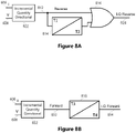
- Figures 8A and 8B illustrate simplified logic diagrams for asserting incremental-quantity directional determinations in accordance with several embodiments.
- Current and voltage measurements 606, 608 are provided to an incremental-quantity directional block 822.
- the incremental-quantity block 822 uses the current and voltage signals 606, 608 to calculate incremental voltage and incremental replica current, and compare polarities thereof. When the polarities are matching, then a reverse signal 812 is asserted. When the polarities are opposite, then a forward signal 832 is asserted.
- extension timers may be used. For example, once the reverse signal 812 is asserted for a pickup time T1, timer 814 asserts for time T2. OR gate 816 asserts the incremental-quantity directional reverse signal 824 upon assertion of the reverse signal 812 or assertion of the timer 814. Similarly, extension timer 818 asserts once the forward signal 832 persists for pickup time T3, and is extended for time T4 to produce the incremental-quantity directional forward signal 834. To avoid extending for a spurious assertion, the extension is only applied if the element 822 asserts for pickup time T3.
- the pickup times T1, T3 may relatively short such as, for example, 1/8 or 1/4 of a cycle.
- Extension times T2 and T4 may be longer than the worst-case fault clearing time for close-in reverse faults, including a breaker failure contingency.
- an incremental-quantity directional forward fault signal 834 may be deemed sufficient to supervise the distance element (permitting protective action). In various other embodiments, both the presence of the incremental-quantity forward fault signal 834 and absence of the incremental-quantity directional reverse fault signal 824 are required for supervising the distance element (permitting protective action).
- Underreaching distance protection applications herein may use incremental-quantity directional logic to supervise the nondirectional operating characteristic. In various applications, it may be beneficial to disable the underreaching zone before the frequency deviation of a low-inertia source causes an overreach.
- the temporary engagement of the zone 1 distance element can be controlled by a disturbance detection logic or a starting zone, or it can use the incremental-quantity directional element for directional supervision and for opening and closing the zone 1 operating window.
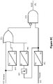
- Figure 8C illustrates a simple logic diagram suitable for underreaching applications.
- the forward fault signal 832 asserts to timer 842.
- the timer 842 with dropout time T5 on the order of 2 to 3 power system cycles allows the distance element to respond to an in-zone fault by asserting to AND gate 848 (which asserts the incremental quantity directional time-limited permissive supervision bit IQ Z1 852).
- the zone 1 element is disabled before frequency deviations can cause an overreach for out-of-zone faults; once the T5 2 to 3 power system cycle operating window closes, the zone 1 element is disabled for the duration of the dropout time T6 of timer 846 (on the order of 1 second). Disabling may occur by assertion of the incremental quantity reverse fault direction signal 812 or upon deassertion of timer 842 (by signal inverter 844 and timer 846 asserting to OR gate 816).
- the distance elements herein may further include faulted loop identification logic.
- Unconventional sources supply fault currents that contain the negative-sequence components that does not follow the negative-sequence voltage and by extension the zero-sequence current. This may be a problem for traditional faulted loop selection.
- unconventional sources are weak (supply low fault current and cannot maintain voltage in the faulted phases).
- an unconventional source supplies the fault current, the voltage in the faulted loop decreases considerably compared with the nominal voltage and compared with the voltages in the healthy loops. Therefore, an undervoltage logic can reliably select the faulted loop.
- the faulted-loop selection logic can be designed to allow a distance protection loop to operate if the loop voltage is below a certain threshold. In other embodiments, the faulted-loop logic can be designed to select the loop with the lowest loop voltage.
- Figures 9A and 9B illustrate logic diagrams that use voltage signals for faulted loop selection.
- Figure 9A illustrates logic for determining an A-phase-to-ground fault loop by comparing the A-phase-to-ground voltage magnitude 902 with a predetermined line-to-ground voltage threshold 904. If the A-phase-to-ground voltage magnitude 902 falls below the line-to-ground voltage threshold 904, then comparator 908 asserts the A-phase-to-ground fault identification signal 910. Similar logic may be used for the B-phase-to-ground loop and the C-phase-to-ground loop. To determine AB fault loop, the AB voltage magnitude 912 is compared with a predetermined line-line voltage threshold 914. If the AB voltage magnitude 912 falls below the line-line voltage threshold 914, then comparator 918 asserts the AB fault identification signal 920. Similar logic may be used for the BC loop and the CA loop.
- Figure 9B illustrates logic that uses a factor (k, k > 1) of the lowest fault loop voltage magnitude as the threshold for determining the fault loop.
- a minimum 930 of the voltage magnitudes of each phase-to-ground loop 902, 922, 924 and each phase-to-phase loop 926, 928, 912 is determined.
- the magnitudes may be multiplied by a compensation factor for proper comparison.
- the illustrated phase-to-phase voltage magnitudes are multiplied by compensation factor 1/ ⁇ 3.
- the minimum of the voltage magnitudes may be multiplied by a factor (k) 932 such as, for example, 1. 1.
- the multiplier 932 may be used to ensure that if two or more loops have a similar loop voltage during a multi-phase fault, the faulted loop selection logic releases all of these loops and does not chatter by repeatedly releasing and blocking two or more loops. If the A-phase-to-ground voltage magnitude falls below the product of the minimum value and the multiplier k 932, then comparator 934 asserts the A-phase-to-ground fault identification signal 910. Similarly, if the AB voltage magnitude falls below the product of the minimum value and the multiplier k 932, then comparator 936 asserts the AB loop fault identification signal 920. Similar comparisons may be made for each of the possible fault loops.
- the present embodiments describe electric power system distance protection for use in systems with unconventional sources.
- the distance protection uses apparent-impedance in an offset (non-directional) distance characteristic, and is directionalized using weak-infeed directional logic, zero-sequence forward ground directional logic, and/or incremental-quantity directional logic.
- Distance protection may include further supervision as described above.
- Figure 10 illustrates a simplified logic diagram for a directional element using the principles described herein. Although the illustrated logic is useful for A-phase-to-ground and AB phase directional protection, similar logic may be used for each of the possible fault loops.
- AND gate 1008 For assertion of an A-phase-to-ground distance fault detection signal 1042, AND gate 1008 must receive the operating signal Z. AG 1014 from the apparent-impedance distance element, the AG fault loop identification signal 910, a directional supervisory signal 1012, a loop overcurrent signal 1016, and an incremental quantity directional time-limited permissive supervision signal 852.
- the incremental quantity directional time-limited permissive supervision signal 852 may be used for zone-1 protection. In various embodiments, the signal 852 is not necessary for overreaching distance protection.
- the signal Z. AG 1014 from the apparent-impedance distance element may be provided by comparing apparent impedance to an offset distance operating characteristic. Apparent impedance may be used to determine the distance fault condition using the offset distance characteristic similar to the phase-to-phase apparent impedance distance element described above.
- the directional supervisory signal 1012 may be provided by either a forward ground directional signal 1002 from the zero-sequence directional logic described above OR 1004 by the incremental-quantity forward signal 834 described above. Accordingly, for phase-to-ground faults, the forward direction signal is used in a supervisory or permissive manner.
- the A-phase-to-ground overcurrent signal 1016 may be asserted when the magnitude of the A-phase-to-ground current exceeds a predetermined overcurrent threshold.
- AND gate 628 For assertion of an AB distance fault detection signal 640, AND gate 628 must receive the signal Z. AB 614 from the apparent-impedance distance element, the AB fault loop identification signal 920, an AB loop overcurrent signal 1018, and the incremental quantity directional time-limited permissive supervision signal 852, while not receiving a reverse direction blocking signal 1020. Absence of the incremental-quantity reverse fault signal 824 and the weak-infeed reverse directional signal 616 are required at OR gate 1006 for assertion of signal 1020 to allow operation of AND gate 628 (assertion of either signal will block assertion of AND gate 628). The AB loop overcurrent signal 1018 may be asserted when the AB loop current magnitude exceeds a predetermined phase-to-phase overcurrent threshold.
- OR gate 1062 Upon assertion of the A-phase-to-ground distance fault signal 1042, the B-phase-to-ground distance fault signal, the C-phase-to-ground distance fault signal, the AB distance fault signal 640, the BC distance fault signal, or the CA distance fault signal, OR gate 1062 asserts the distance fault signal 1082.
- a protective system may use the distance fault signal 1082 to determine a protective action and effect a protective action such as tripping a circuit breaker.
- FIG. 11 illustrates a simplified logic diagram that may be used by an IED in the determination of whether to use traditional distance element principles 1102 or modified distance element principles 1108. The determination as illustrated is based on an overcurrent principle. The determination may be made on a per-fault-loop basis. The determination compares the loop current 1106 with a strong-weak current threshold 1104 in comparator 1110.
- the strong-weak current threshold should be higher than a current that an unconventional source would be expected to maintain for a fault condition. If the loop current 1106 for the selected fault loop exceeds the threshold 1104, and the traditional distance element 1102 asserts a distance fault signal for the selected fault loop, then AND gate 1112 asserts the distance fault signal for the selected fault loop. If, however, the loop current 1106 for the selected fault loop does not exceed the threshold 1104, and the modified distance element 1108 asserts a distance fault signal for the selected fault loop, then AND gate 1114 asserts the distance fault signal. Upon assertion of the distance fault signal from either AND gate 1112, 1114, OR gate 1116 asserts the distance fault signal 1082 useful for determining a protective action and asserting a protective action.
Landscapes
- Physics & Mathematics (AREA)
- General Physics & Mathematics (AREA)
- Emergency Protection Circuit Devices (AREA)
Applications Claiming Priority (2)
| Application Number | Priority Date | Filing Date | Title |
|---|---|---|---|
| US202163166065P | 2021-03-25 | 2021-03-25 | |
| US17/685,647 US11598800B2 (en) | 2021-03-25 | 2022-03-03 | Distance elements for line protection near unconventional sources |
Publications (1)
| Publication Number | Publication Date |
|---|---|
| EP4064488A1 true EP4064488A1 (de) | 2022-09-28 |
Family
ID=80819641
Family Applications (1)
| Application Number | Title | Priority Date | Filing Date |
|---|---|---|---|
| EP22162845.6A Pending EP4064488A1 (de) | 2021-03-25 | 2022-03-17 | Abstandselemente für den leitungsschutz in der nähe von unkonventionellen quellen |
Country Status (2)
| Country | Link |
|---|---|
| US (1) | US11598800B2 (de) |
| EP (1) | EP4064488A1 (de) |
Cited By (2)
| Publication number | Priority date | Publication date | Assignee | Title |
|---|---|---|---|---|
| CN118336660A (zh) * | 2024-05-15 | 2024-07-12 | 河南许继继保电气自动化有限公司 | 一种新能源场站送出线自适应距离保护方法和装置 |
| CN120831541A (zh) * | 2025-09-17 | 2025-10-24 | 山东山大电力技术股份有限公司 | 一种用于电力系统的故障研判方法及装置 |
Families Citing this family (7)
| Publication number | Priority date | Publication date | Assignee | Title |
|---|---|---|---|---|
| US11650241B1 (en) | 2022-06-28 | 2023-05-16 | Schweitzer Engineering Laboratories, Inc. | Incremental quantities-based fault locating technique and system |
| US12287362B2 (en) | 2022-11-07 | 2025-04-29 | Ge Infrastructure Technology Llc | Systems and methods for identifying grid fault type and faulted phase |
| US12362556B2 (en) | 2023-03-07 | 2025-07-15 | Schweitzer Engineering Laboratories, Inc. | Single-ended broken conductor detection logic using incremental quantities |
| EP4702631A1 (de) * | 2023-04-28 | 2026-03-04 | Hitachi Energy Ltd | Verfahren und system zur adaptiven gewinnung einer korrigierten scheinbaren impedanz |
| EP4456359A1 (de) * | 2023-04-28 | 2024-10-30 | Hitachi Energy Ltd | Verfahren und system zur adaptiven gewinnung einer korrigierten scheinbaren impedanz |
| EP4557544A1 (de) * | 2023-11-17 | 2025-05-21 | Hitachi Energy Ltd | Identifizierung der fehlerrichtung für mit wechselrichterbasierten erneuerbaren ressourcen verbundene stromnetze |
| EP4618343A1 (de) * | 2024-03-11 | 2025-09-17 | Hitachi Energy Ltd | Distanzschutz für symmetrische dreiphasige fehler |
Citations (3)
| Publication number | Priority date | Publication date | Assignee | Title |
|---|---|---|---|---|
| US20160077149A1 (en) * | 2014-09-16 | 2016-03-17 | Schweitzer Engineering Laboratories, Inc. | Fault detection in electric power delivery systems using underreach, directional, and traveling wave elements |
| CN110544925A (zh) * | 2019-06-17 | 2019-12-06 | 国网西藏电力有限公司电力科学研究院 | 确定光伏场站送出线故障点的线路保护范围的方法、系统 |
| US20200103455A1 (en) * | 2018-09-27 | 2020-04-02 | Schweitzer Engineering Laboratories, Inc. | Secure distance protection of electric power delivery systems under transient conditions |
Family Cites Families (18)
| Publication number | Priority date | Publication date | Assignee | Title |
|---|---|---|---|---|
| US4342064A (en) | 1978-02-21 | 1982-07-27 | General Electric Company | Static distance relays with improved polarizing signal |
| US4420788A (en) | 1982-07-29 | 1983-12-13 | General Electric Company | Phase relay for AC power transmission line protection |
| US4686601A (en) | 1985-10-02 | 1987-08-11 | General Electric Company | Ground distance relay for AC power transmission line protection |
| US4821137A (en) | 1987-11-12 | 1989-04-11 | General Electric Company | Positive sequence distance relay for AC power transmission line protection |
| US5140492A (en) | 1990-04-11 | 1992-08-18 | Schweitzer Engineering Laboratories, Inc. | Distance relay using a polarizing voltage |
| US5367426A (en) | 1992-10-14 | 1994-11-22 | Schweitzer Engineering Laboratories, Inc. | Distance relay with load encroachment protection, for use with power transmission lines |
| US5790418A (en) | 1995-10-17 | 1998-08-04 | Schweitzer Engineering Laboratories, Inc. | Adaptive polarizing memory voltage time constant |
| US6028754A (en) | 1995-10-20 | 2000-02-22 | Schweitzer Engineering Laboratories, Inc. | System for preventing undesired protective relay tripping actions due to coupling capacitor voltage transformer transients |
| DE19605025C2 (de) | 1996-01-31 | 2003-06-18 | Siemens Ag | Distanzschutzverfahren |
| US6239959B1 (en) | 1999-06-30 | 2001-05-29 | General Electric Company | Ground distance relay for AC power transmission line protection |
| US20060152866A1 (en) | 2005-01-13 | 2006-07-13 | Gabriel Benmouyal | System for maintaining fault-type selection during an out-of-step condition |
| US8675327B2 (en) | 2007-03-30 | 2014-03-18 | General Electric Company | Fast impedance protection technique immune to dynamic errors of capacitive voltage transformers |
| CA2774517C (en) | 2009-09-18 | 2015-01-27 | Schweitzer Engineering Laboratories, Inc. | Electrical power system phase and ground protection using an adaptive quadrilateral characteristic |
| US9257827B2 (en) | 2009-09-18 | 2016-02-09 | Schweitzer Engineering Laboratories, Inc. | Electrical power system phase and ground protection using an adaptive quadrilateral characteristic |
| US10114052B2 (en) | 2015-02-25 | 2018-10-30 | Schweitzer Engineering Laboratories, Inc. | Estimation of a waveform period |
| US9941684B2 (en) | 2015-05-12 | 2018-04-10 | Schweitzer Engineering Laboratories, Inc. | Phase and ground protection using tilt-limited adaptive quadrilateral characteristic |
| US10677834B2 (en) | 2018-09-14 | 2020-06-09 | Schweitzer Engineering Laboratories, Inc. | Distance protection of electric power delivery systems using time domain and frequency domain |
| US10978866B2 (en) * | 2018-10-02 | 2021-04-13 | Schweitzer Engineering Laboratories, Inc. | Polarizing signal for electric power delivery system protection |
-
2022
- 2022-03-03 US US17/685,647 patent/US11598800B2/en active Active
- 2022-03-17 EP EP22162845.6A patent/EP4064488A1/de active Pending
Patent Citations (3)
| Publication number | Priority date | Publication date | Assignee | Title |
|---|---|---|---|---|
| US20160077149A1 (en) * | 2014-09-16 | 2016-03-17 | Schweitzer Engineering Laboratories, Inc. | Fault detection in electric power delivery systems using underreach, directional, and traveling wave elements |
| US20200103455A1 (en) * | 2018-09-27 | 2020-04-02 | Schweitzer Engineering Laboratories, Inc. | Secure distance protection of electric power delivery systems under transient conditions |
| CN110544925A (zh) * | 2019-06-17 | 2019-12-06 | 国网西藏电力有限公司电力科学研究院 | 确定光伏场站送出线故障点的线路保护范围的方法、系统 |
Non-Patent Citations (1)
| Title |
|---|
| IEEE STANDARD BOARD: "IEEE guide for protective relay applications to transmission lines", 29 February 2000, IEEE STANDARD; [IEEE STANDARD], IEEE, PISCATAWAY, NJ, USA, ISBN: 978-0-7381-1831-4, XP017601233 * |
Cited By (2)
| Publication number | Priority date | Publication date | Assignee | Title |
|---|---|---|---|---|
| CN118336660A (zh) * | 2024-05-15 | 2024-07-12 | 河南许继继保电气自动化有限公司 | 一种新能源场站送出线自适应距离保护方法和装置 |
| CN120831541A (zh) * | 2025-09-17 | 2025-10-24 | 山东山大电力技术股份有限公司 | 一种用于电力系统的故障研判方法及装置 |
Also Published As
| Publication number | Publication date |
|---|---|
| US11598800B2 (en) | 2023-03-07 |
| US20220308103A1 (en) | 2022-09-29 |
Similar Documents
| Publication | Publication Date | Title |
|---|---|---|
| EP4064488A1 (de) | Abstandselemente für den leitungsschutz in der nähe von unkonventionellen quellen | |
| US11056874B2 (en) | Fault detection and protection during steady state using traveling waves | |
| US10333291B2 (en) | Multiple generator ground fault detection | |
| US10641815B2 (en) | Secure distance protection of electric power delivery systems under transient conditions | |
| US7457088B2 (en) | Systems and methods for protection of electrical networks | |
| US10677834B2 (en) | Distance protection of electric power delivery systems using time domain and frequency domain | |
| US8410785B2 (en) | Electrical power system phase and ground protection using an adaptive quadrilateral characteristics | |
| CN101788633B (zh) | 一种判别电压互感器回路断线的方法 | |
| US20170108542A1 (en) | Determining status of electric power transmission lines in an electric power transmission system | |
| US10931097B2 (en) | Generator stator ground protection using third harmonic | |
| US10578653B2 (en) | Overexcitation protection for electric power system equipment | |
| CN110297159A (zh) | 用于确定电力系统补偿网络中的故障线路的方法与装置 | |
| US9478966B2 (en) | Electric network protection | |
| US20230069041A1 (en) | Detection of incipient failures in instrument transformers | |
| US20100254056A1 (en) | Efficient method for calculating the dot product in fault detection algorithms | |
| US11411390B2 (en) | Secure and dependable restricted earth fault protection for electric power generators and transformers | |
| US11469588B2 (en) | Electric power system differential protection with DC compensation | |
| US20250357751A1 (en) | Limiting distance elements overreach for incoming power flow | |
| US12176716B2 (en) | Line reactor protection security using local frequency measurement | |
| US20260074509A1 (en) | High-speed high-sensitivity transformer differential protection using enhanced restraining techniques | |
| CN113852046B (zh) | 一种防止线路电抗器采用母线pt时匝间保护误动的方法及系统 | |
| US20250279255A1 (en) | Protection through a power transformer using compensated voltages and currents | |
| Stinskiy et al. | Inrush Detection Through Current Wave Shape Analysis–Advanced Transformer Protection for Power Grids with IBRs | |
| Dubey et al. | A Differential Decaying DC Component Based Unit Protection For Transmission Networks With SFCL | |
| Deng et al. | A Novel Bus-bar Protection Principle Based on Model Parameter Identification |
Legal Events
| Date | Code | Title | Description |
|---|---|---|---|
| PUAI | Public reference made under article 153(3) epc to a published international application that has entered the european phase |
Free format text: ORIGINAL CODE: 0009012 |
|
| STAA | Information on the status of an ep patent application or granted ep patent |
Free format text: STATUS: REQUEST FOR EXAMINATION WAS MADE |
|
| 17P | Request for examination filed |
Effective date: 20220318 |
|
| AK | Designated contracting states |
Kind code of ref document: A1 Designated state(s): AL AT BE BG CH CY CZ DE DK EE ES FI FR GB GR HR HU IE IS IT LI LT LU LV MC MK MT NL NO PL PT RO RS SE SI SK SM TR |
|
| P01 | Opt-out of the competence of the unified patent court (upc) registered |
Effective date: 20230529 |