EP4064475B1 - Anschlussschrank - Google Patents
Anschlussschrank Download PDFInfo
- Publication number
- EP4064475B1 EP4064475B1 EP22164291.1A EP22164291A EP4064475B1 EP 4064475 B1 EP4064475 B1 EP 4064475B1 EP 22164291 A EP22164291 A EP 22164291A EP 4064475 B1 EP4064475 B1 EP 4064475B1
- Authority
- EP
- European Patent Office
- Prior art keywords
- drawer
- electrical
- module
- column
- connection
- Prior art date
- Legal status (The legal status is an assumption and is not a legal conclusion. Google has not performed a legal analysis and makes no representation as to the accuracy of the status listed.)
- Active
Links
Images


Classifications
-
- H02J13/10—
-
- H—ELECTRICITY
- H05—ELECTRIC TECHNIQUES NOT OTHERWISE PROVIDED FOR
- H05K—PRINTED CIRCUITS; CASINGS OR CONSTRUCTIONAL DETAILS OF ELECTRIC APPARATUS; MANUFACTURE OF ASSEMBLAGES OF ELECTRICAL COMPONENTS
- H05K7/00—Constructional details common to different types of electric apparatus
- H05K7/14—Mounting supporting structure in casing or on frame or rack
- H05K7/1462—Mounting supporting structure in casing or on frame or rack for programmable logic controllers [PLC] for automation or industrial process control
- H05K7/1465—Modular PLC assemblies with separable functional units
-
- H—ELECTRICITY
- H02—GENERATION; CONVERSION OR DISTRIBUTION OF ELECTRIC POWER
- H02B—BOARDS, SUBSTATIONS OR SWITCHING ARRANGEMENTS FOR THE SUPPLY OR DISTRIBUTION OF ELECTRIC POWER
- H02B1/00—Frameworks, boards, panels, desks, casings; Details of substations or switching arrangements
- H02B1/26—Casings; Parts thereof or accessories therefor
- H02B1/30—Cabinet-type casings; Parts thereof or accessories therefor
- H02B1/32—Mounting of devices therein
- H02B1/34—Racks
- H02B1/36—Racks with withdrawable units
-
- H—ELECTRICITY
- H02—GENERATION; CONVERSION OR DISTRIBUTION OF ELECTRIC POWER
- H02B—BOARDS, SUBSTATIONS OR SWITCHING ARRANGEMENTS FOR THE SUPPLY OR DISTRIBUTION OF ELECTRIC POWER
- H02B1/00—Frameworks, boards, panels, desks, casings; Details of substations or switching arrangements
- H02B1/26—Casings; Parts thereof or accessories therefor
- H02B1/30—Cabinet-type casings; Parts thereof or accessories therefor
-
- H—ELECTRICITY
- H02—GENERATION; CONVERSION OR DISTRIBUTION OF ELECTRIC POWER
- H02B—BOARDS, SUBSTATIONS OR SWITCHING ARRANGEMENTS FOR THE SUPPLY OR DISTRIBUTION OF ELECTRIC POWER
- H02B1/00—Frameworks, boards, panels, desks, casings; Details of substations or switching arrangements
- H02B1/56—Cooling; Ventilation
- H02B1/565—Cooling; Ventilation for cabinets
-
- H—ELECTRICITY
- H02—GENERATION; CONVERSION OR DISTRIBUTION OF ELECTRIC POWER
- H02B—BOARDS, SUBSTATIONS OR SWITCHING ARRANGEMENTS FOR THE SUPPLY OR DISTRIBUTION OF ELECTRIC POWER
- H02B11/00—Switchgear having carriage withdrawable for isolation
- H02B11/02—Details
- H02B11/10—Indicating electrical condition of gear; Arrangement of test sockets
-
- H02J13/12—
-
- H02J13/13—
-
- H02J13/1321—
-
- H02J13/1331—
-
- H02J13/1337—
-
- H—ELECTRICITY
- H05—ELECTRIC TECHNIQUES NOT OTHERWISE PROVIDED FOR
- H05K—PRINTED CIRCUITS; CASINGS OR CONSTRUCTIONAL DETAILS OF ELECTRIC APPARATUS; MANUFACTURE OF ASSEMBLAGES OF ELECTRICAL COMPONENTS
- H05K7/00—Constructional details common to different types of electric apparatus
- H05K7/14—Mounting supporting structure in casing or on frame or rack
- H05K7/1462—Mounting supporting structure in casing or on frame or rack for programmable logic controllers [PLC] for automation or industrial process control
- H05K7/1475—Bus assemblies for establishing communication between PLC modules
-
- H—ELECTRICITY
- H02—GENERATION; CONVERSION OR DISTRIBUTION OF ELECTRIC POWER
- H02B—BOARDS, SUBSTATIONS OR SWITCHING ARRANGEMENTS FOR THE SUPPLY OR DISTRIBUTION OF ELECTRIC POWER
- H02B1/00—Frameworks, boards, panels, desks, casings; Details of substations or switching arrangements
- H02B1/20—Bus-bar or other wiring layouts, e.g. in cubicles, in switchyards
- H02B1/202—Cable lay-outs
Definitions
- the invention aims to remedy these drawbacks in particular by proposing an electrical connection cabinet enabling the data exchanges between the industrial computer and the control-command units to be grouped together, as well as an auxiliary electrical voltage supply for the control-command units.
- a longitudinal axis X of the electrical cabinet 100 is defined as being the axis of the largest dimension of the electrical cabinet 100, in practice its length, a transverse axis Y as being the axis of the smallest dimension of the electrical cabinet 100 and perpendicular to the axis X, in practice its width, and a vertical axis Z as being the third axis of an orthogonal reference frame comprising the axes X and Y.
- the orientation of the X, Y and Z axes is fixedly linked to the orientation of the electrical cabinet 100.
- the orientation of the electrical cabinet 100 described in the present disclosure corresponds to its installed configuration. It is therefore understood that the orientation of the X, Y and Z axes varies when the orientation of the electrical cabinet 100 varies.
- the Z axis may not be vertical when the cabinet 100 is not in the installed configuration, for example when it is transported.
- the terms “top”, “bottom” and “vertical” used in the remainder of the disclosure are understood to relate to the Z axis.
- the electrical loads 104 may for example be electric motors, such as three-phase motors, electricity distribution networks, or even controllable electrical loads, such as batteries or photovoltaic panels.
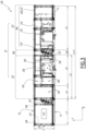
- the electrical cabinet 100 comprises an electrical distribution column 108 and two connection columns 110, arranged on either side of the electrical distribution column 108.
- a connection column 110 is always juxtaposed with an electrical distribution column 108.
- An electrical distribution column 108 is always juxtaposed with one or two connection columns 110.
- an electrical distribution column 108 and one or two connection columns 110 forms a functional column 111.
- a functional column 111 comprises two connection columns 110, these two columns are located respectively on either side, namely on the left and on the right on the figures 1 to 5 , of the electrical distribution column 108.
- a functional column 111 comprises a single connection column 110, this column is located indifferently, on one side or the other, namely on the left or on the right on the figures 1 to 5 , from the electrical distribution column 108.
- the electrical cabinet 100 comprises several functional columns 111, juxtaposed along the X axis.
- Height H1 also corresponds to the height of the electrical cabinet 100.
- the power column 106 makes it possible to supply the entire electrical cabinet 100 with electrical energy from the power cable 102.
- the power column is arranged at a longitudinal end of the cabinet 100, as in the example shown, where the power column is to the left of the cabinet 100.
- each phase and the neutral of the power cable 102 are connected to an input of a circuit breaker 112.
- the power column 106 also comprises a set of power bars 114 comprising several power bars 116. Each output of the circuit breaker 112 is connected to a power bar 116.
- the set of bars 114 of the column 106 comprises four power bars 116, corresponding to the three phases and the neutral of the power supply current.
- the horizontal busbar 118 extends along the longitudinal axis X of the electrical cabinet 100 and makes it possible to supply each electrical distribution column 108 of the cabinet.
- a horizontal sheath 119 is provided over the entire length of the electrical cabinet 100 and accommodates the horizontal busbar 118.
- the communication module 134 communicates with the industrial computer 130 via the communication cables 132, on the one hand to transmit information on the operation of the connection column 110 and on the other hand to receive the commands coming from the industrial computer and to be transmitted to the connection column.
- each communication module 134 in practice comprises a controlled network switch 135, called a “managed switch”.
- connection columns 110 When the electrical cabinet 100 comprises several connection columns 110, as in the example shown in figures 1 to 3 , the communication modules 134 of each connection column are connected to each other in series by internal communication cables 136. In practice, it is the managed switches 135 of the communication modules which are connected to each other by the internal communication cables 136.
- Such a configuration has the advantage of making the operation of the electrical cabinet 100 more reliable. Indeed, in the event of failure of a communication module 134, only the operation of the connection column 110 comprising this module will be affected because, the other non-failing modules being interconnected and connected to the central switch 137, their connection to the industrial computer 130 will not be interrupted by the faulty module.
- a central switch 137 is arranged between the communication module and the industrial computer.
- the internal communication cables 136 are cables using the Ethernet protocol.
- the internal communication cables 136 use another local network protocol, such as for example the MODBUS or PROFINET protocol.
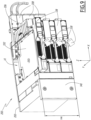
- each connection column 110 comprises one or more control-command units 138.
- connection cables 139 The electrical loads 104 being distant from the cabinet 100, their connection to the control-command units 138 is carried out by means of connection cables 139.
- control-command units 138 are control-command drawers which can therefore be installed in, and removed from, the connection column 110 simply and quickly.
- control-command units 138 are fixed units of the cabinet, which are assembled during installation of the cabinet, for example by screwing into the column(s) 110.
- a control-command unit 138 allows the electrical connection of an electrical load 104.
- connection column 110 comprises up to thirty control-command units 138 and therefore allows the connection of a maximum of thirty electrical loads 104.
- a connection column 110 is modular, that is to say that it is possible to install as many control-command units as desired, between one unit and thirty units.
- the control-command units 138 are juxtaposed vertically in the connection column 110.
- a connecting column 110 may comprise more than thirty control-command units 138, for example if the height of a control-command unit is reduced or if the height of the connecting column 110 is increased.
- the control-command units 138 also allow the control of the electrical loads 104 which are connected thereto.
- This control also called piloting, consists, for example, when the electrical load is a motor, in piloting this motor, that is to say to start it, stop it and possibly control its speed, or, when the electrical load is a distribution network, to deliver the voltage and intensity necessary for the proper functioning of this distribution network.
- control-command units 138 also allow the monitoring of the electrical loads 104 connected thereto. This monitoring consists, for example, of measuring the voltage and current delivered to the load 104, or of retrieving information from sensors such as, for example, position or rotation speed sensors or temperature sensors when the load 104 is a motor.
- each control-command unit 138 may have a role of connecting an electrical load 104, controlling this load and monitoring this load. However, depending on the type of electrical load 104 connected to a control-command unit 138, this control-command unit may not have a role of controlling this load, or may not have a role of controlling the load.
- each connection column 110 comprises one or more protection units 140.
- Each protection unit 140 is configured to electrically protect one or more control-command units 138 as well as the electrical loads 104 which are connected to these control-command units, in particular in the event of failure of an electrical load 104, such as for example a short circuit.
- the protection units 140 are, for example, circuit breakers arranged upstream of the control-command units 138 and which make it possible to interrupt the electric current supplying the loads 104 via the control-command units 138 in the event of an incident, for example in the event of a short circuit. In other words, the protection units 140 control the power supply to the control-command units 138.
- the vertical busbar 122 is a source of electricity for each protection unit 140.
- Each computer bus 142 also has power supply tracks 148, visible in the figure 25 , configured to conduct a first auxiliary electrical voltage, which makes it possible to supply the control-command units 138 with the first auxiliary electrical voltage, this first auxiliary voltage being necessary for the operation of certain components of the control-command units 138, detailed below.
- This first auxiliary voltage comes from the communication module 134 of each connection column 110.
- This first auxiliary voltage is for example a direct electrical voltage of 48V.
- the first auxiliary voltage is a voltage of a different value, such as 12V, 24V, 110V direct current or 110V alternating current.
- each communication module 134 comprises at least one power supply unit 150.
- each communication module 134 comprises two power supplies 150 which are redundant, as in the example shown in figures 6 And 7
- Such a configuration is advantageous because in the event of failure of a power supply unit 150, the operation of the communication module 134 containing this unit and the operation of the connection column 110 containing this module are not interrupted.
- the computer bus 142 is a six-layer printed circuit board, with the power supply tracks 148 and 154 and the electronic circuits 144 distributed between these six layers.
- the computer bus 142 comprises a different number of layers.
- the power supply tracks 148 and 154 of the computer bus 142 are replaced by electrical cables attached to the computer bus.
- the thermal management zone 162 is located at the rear of the connection column 110, in the vicinity of the rear face F2, and extends, in length, that is to say along the X axis, from the electrical distribution column 108 to the wiring zone 160.
- connection column 110 and the internal arrangement of the right connection column 110 are symmetrical with respect to a plane of symmetry P2 parallel to the vertical plane formed by the axes Y and Z and passing through the center of the electrical distribution column 108.
- the functional area 156 extends over a height H2 less than the height H1, which makes it possible to install the communication module 134 above the functional area 156, as in the example shown in figures 1 to 3 , or below this area.
- connection column 110 comprises the maximum number of control-command units 138, for example thirty units in the example shown, then these control-command units occupy the majority of the functional zone 156.
- the functional area 156 is not entirely occupied by control-command units and comprises a free space.
- the communication module 134 can also be installed in the free space of the functional area 156.
- the height H2 is 1500 mm; it could be different as a variant.
- connection zone 158 extends over a height H3 less than the height H1 and greater than the height H2.
- the height H3 is equal to the sum of the height H2 and the height of the communication module 134.
- the height of the computer bus 142 is equal to the height H3.
- the height H3 is 1600 mm.
- the wiring zones 160 and thermal management 162 extend over the entire height H1 of the functional column 111. In practice, the horizontal sheath 119 therefore passes through the wiring zone 160.
- the horizontal sheath 119 preferably passes above or below the functional 156 and connection 158 zones, so as not to pass into the thermal management zone 162.
- connection of the connection cables 139 to the control-command units 138 is carried out via the front face F1 of the cabinet 100.
- the width of the functional column 111, and therefore of the cabinet 100 is 600 mm.
- the width of the wiring zone 160 is therefore also 600 mm.
- the width of the functional zones 156 and the connection zones 158, denoted “l2”, is preferably 400 mm.
- the width of the thermal management zone 162, denoted “l3”, is therefore 200 mm.
- FIG. 5 illustrates the interior arrangement of a third embodiment of a cabinet 100 with a functional column 111.
- This third embodiment differs from the embodiment of the figures 1 to 3 in that the connection of the connection cables 139 to the control-command units 138 is carried out via the rear face F2 of the cabinet 100.
- the functional column 111 does not include a dedicated wiring zone 160 and the connections are made in the thermal management zone 162.
- the widths l1, l2 and l3 are the same as in the embodiment of the figures 1 to 3 .
- the internal communication cables 136 are preferably positioned, depending on the height of the cabinet 100, opposite the horizontal busbar 118 in order to avoid any electromagnetic interference. In practice, this means that, preferably, the cables 136 are positioned at the top of the cabinet 100 when the horizontal sheath 119 is located at the bottom of the cabinet and these cables are positioned at the bottom of the cabinet when this horizontal sheath is located at the top of the cabinet.
- the length L111 of a functional column 111 comprising two connection columns 110 is preferably equal to 2650 mm in a configuration where each connection column comprises a wiring zone.
- the length L5 is equal to the length L3 and the length L111 of a functional column 111 is preferably equal to 2050 mm.
- the lengths L1, L2, L3, L4, L5 and L111 are different.
- the cabinet 100 in practice comprises a frame 164 and covering sheets 166.
- the frame 164 comprises several frames 168 and crosspieces 170, the crosspieces 170 connecting the frames together and each frame being formed by four bars 172.
- the covering sheets 166 are fixed to the frame 164 so as to close the front F1, rear F2, upper F4, left F5 and right F6 faces of the cabinet 100. Thus, the interior of the cabinet 100 is protected.
- the cabinet 100 does not include a covering sheet 166 over the entire front face F1 of the connection columns 110 of the cabinet 100, so that one face of each communication module 134, of each control-command unit 138 and of each protection unit 140 is accessible from the outside.
- the communication modules and the protection and connection units are protected by covering sheets 166.
- Each covering sheet 166 may further be a door, which allows access to the interior of the cabinet 100.
- the covering sheets 166 may be opaque or transparent.
- Figure 1 represents the case where the covering sheets 166 located at the level of the power column 106 and the wiring zones 160 are opaque.
- the frame 164 also comprises reinforcements 174, which extend from the rear face F2 of the cabinet over a distance of 200 mm.
- the reinforcements 174 extend over the entire width of the thermal management zone 162, up to the interface between this thermal management zone and the functional 156 and connection 158 zones.
- each column - power supply, electrical distribution and connection - of the cabinet 100 comprises an independent frame and the frames of two adjacent columns are linked together, for example using screws, which allows great modularity in the design and in the assembly of a cabinet 100.
- the communication module 134 comprises a front face 176 and a rear face 178.
- the communication module extends over a width l134 of 400 mm.
- the front face 176 of the module is at the level of the front face F1 of the column and of the cabinet and the rear face 178 of the module is either at the level of the rear face of the cabinet, when the cabinet has a width l2 of 400 mm as in the embodiment of the Figure 4 , either at the level of the reinforcements 174, when the cabinet 100 has a width l1 of 600 mm, as in the embodiments of the figures 1 to 3 And 5 .
- the locks 182 are arranged symmetrically with respect to a median plane ⁇ 134 of the drawer 134 and make it possible to maintain the communication module 134 mounted in the connection column 110 by cooperating with the frame 164. They can be actuated from outside the cabinet 100, via its front face F1.
- a rear ventilation grille 184 On the rear face 178 is provided a rear ventilation grille 184.
- the ventilation grille 184 connects the interior of the communication module with the exterior of the cabinet.
- the ventilation grille 184 connects the interior of the communication module with the thermal management area 162.
- the two redundant power supplies 150 are connected to an electronic card 188.
- the electronic card 188 comprises two connectors 189, on which the power supplies 150 are plugged.
- the electronic card 188 allows the two power supplies 150 to be controlled and the first auxiliary electrical voltage to be managed.
- the electronic card 188 is configured to, in the event that one of the two power supply units 150 is faulty, alert of this fault, for example by means of an indicator 185, but continues to manage the first auxiliary electrical voltage, supplied by the second non-faulty power supply unit.
- the front face 176 of the communication module comprises a cover 190.
- This cover 190 is removable from the front face 176 and is arranged opposite the two power supply units 150.
- This replacement of a power supply unit during operation is advantageous because it allows the operation of the connection column 110 not to be stopped.
- the electronic card 188 supplies the managed switch 135 with first auxiliary electrical voltage to enable the operation of this switch.
- the side face 187 which carries the first and second connectors also comprises two communication connectors 198 connected to the managed switch 135.
- a first connector allows the connection of an internal communication cable 136 connected to the communication module of another connection column 110, in the case where the cabinet 100 comprises several connection columns 110
- a second connector allows the connection of an internal communication cable 136 connected to the central switch 137.
- the first and second connectors are each connected to a communication module of another connection column 110, so as to connect three connection columns together.
- the communication module 134 comprises a number of communication connectors 198 other than two, for example one or three.
- Openings are provided in the side rails 186 to allow access to the connectors 192, 196 and 198 when the communication module is mounted on the side rails.
- this module can be transposed to other configurations, such as in the case of a current distribution column, where the motor starter module then corresponds to a distribution module which makes it possible to distribute an electric current to one or more downstream circuits and to protect these circuits, or in the case of a load control column, where the motor starter module then corresponds to a control module which makes it possible to supply electrical loads and to control them.
- a current distribution column where the motor starter module then corresponds to a distribution module which makes it possible to distribute an electric current to one or more downstream circuits and to protect these circuits, or in the case of a load control column, where the motor starter module then corresponds to a control module which makes it possible to supply electrical loads and to control them.
- the motor starter module then corresponds to a distribution module which makes it possible to distribute an electric current to one or more downstream circuits and to protect these circuits, or in the case of a load control column, where the motor starter module then corresponds to a control module which makes it possible to supply electrical loads and to control them.
- Other uses
- the term “functional module” refers to any module whose architecture can be transposed from the architecture described below of an engine starter module 200, such as for example a distribution module or a control module.
- the engine starter column 110 comprises one or more engine starter modules 200, one of which is visible at figures 8 And 9 .
- Each engine starter module 200 of an engine starter column 110 is mainly located in the functional area 156 and partially located in the connection area 158 of this engine starter column.
- the rails 250 are arranged on the inner face 238 of the protection unit.
- All 138 drawers include a front part 300, which is different depending on the height of the drawer.
- the height of the front part is adapted to the height of the drawer of this front part.
- a front part 300 can therefore have a height of 1U, 2U, 3U, 4U, 5U or 6U.
- the electromagnetic lock 311 extends outside the drawer and mechanically blocks its insertion into the engine starter module or its exit from the engine starter module, as detailed below.
- the electromagnetic lock 311 is in the drawer locking position 138 and the lock switches to the drawer unlocking position when it receives an opening command. In the absence of an opening command, the lock switches to the default drawer locking position.
- the button 310 makes it possible, when actuated, to send an opening command controlling the unlocking of the electromagnetic lock 311 and thus to authorize the movement of the drawer from its operating position or from its test position.
- the electromagnetic lock 311 controlled by the button 310 prevents the insertion of the drawer 138 from its test position to its operating position, or the exit of the drawer 138 from its operating position, by interfering with the rail 224 or with the rail 250.
- the following description of the operation of the electromagnetic lock 311 applies identically to an electromagnetic lock disposed on the side of a rail 250 and interfering with this rail 250 to prevent the movement of the drawer 138.
- the electromagnetic lock 311 comprises a tilting lever 3111 and a bolt 3113 arranged at a first end 3115 of the tilting lever 3111.
- the tilting lever is rotatable about a second end 3117.
- the electromagnetic lock 311 receives an opening command, the tilting lever 3111 is rotated so as to move the bolt 3113.
- the bolt 3113 is arranged in a slot 2241 of the rail 224, when the drawer 138 is in the test position, or in another slot 2243 of the same rail 224, when the drawer is in the operating position.
- the rotation of the rocking lever 3111 is driven by an electromagnetic actuator, not shown.
- This electromagnetic actuator is activated when the electromagnetic lock 311 receives an opening command.
- the actuation of the button 310 generates an opening command, which is an electrical signal, which controls the activation of the actuator of the electromagnetic lock 311.
- the electromagnetic lock 311 does not include a tilting lever that can rotate and the bolt 3113 is driven in translation by an electromagnetic actuator, for example via a slider.
- the base 306 includes a pull tab 312, accessible through a window 314 of the base 306.
- the pull rod 312 mechanically prevents the button 310 from being actuated. In other words, in this position, it is not possible to send an opening command to the electromagnetic lock 311 and, therefore, it is not possible to move the drawer 138 from its operating position or from its test position in the engine starter module 200.
- the lug 844 is arranged in the part 842 of the guide rail 838, as shown in figure 39 .
- the actuating lever 832 makes it possible to convert a translational movement of the pull rod 312 along an axis parallel to the X axis of the drawer 138 into a translational movement of the rod 826 along an axis parallel to the Y axis of the drawer, that is to say in a direction perpendicular to the direction of the translation of the pull rod 312.
- the hooks 856 do not extend into the notches 2245 and do not prevent the movement of the drawer 138 in the engine starter module.
- Each latch 850 further comprises a cam 862 which is oriented towards the other latch 850.
- the two cams 862 are located opposite each other.
- the second end 830 of the rod 826 is located between the cams 862 of the latches 850.
- This second end 830 being thin, the cams 862 are brought together and the hooks 856 are sufficiently far from the rail 224 so as not to extend into the notches 2245 of the rail.
- the rod 826 is moved so that the main body 829 of the rod is located between the cams 862 of the 850 latches, as seen in the figure 36 .
- the latches 850 are moved away from each other and the hooks 856 extend into the notches 2245 of the rail 224.
- the notches 2245 of the rail 224 are provided at a specific location, so that the hooks 856 can extend therein only when the drawer 138 is in the test position.
- the mechanical lock 820 therefore makes it possible to lock the drawer 138 in the test position.
- the mechanical lock 820 is movable between two positions: a drawer locking position 138, in which the drawer is in the test position, and a drawer unlocking position 138, in which the mechanical lock 820 does not oppose the movement of the drawer 138.
- a locking device can be placed in the hole 316 of the handle, which then prevents the pull tab from passing into the unlocking position of the button 310 and therefore the mechanical lock 820 from passing into the unlocking position of the drawer 138.
- the pull 312 allows the mechanical lock 820 to be operated.
- the drawer locking system 138 thus comprises two separate locking mechanisms, i.e. the electromagnetic lock 311 and the mechanical lock 820.
- pull tab 312 interacts with these two locking mechanisms, because, depending on its position, the pull tab 312 allows or prevents the activation of the button 310, which controls the electromagnetic lock 311, and moves the mechanical lock 820 between its locking or unlocking positions of the drawer 138.
- the electromagnetic lock 311 makes it possible to lock the drawer 138 either in the operating position or in the test position
- the mechanical lock 820 makes it possible to lock the drawer 138 in the test position.
- the electromagnetic lock 311 can only be unlocked when the mechanical lock 820 is unlocked.
- Locking the position of the drawer 138 in the test position is then redundant, which is particularly advantageous for securing the use of the drawer 138 and the electrical load 104 connected to it.
- the maintenance worker installs a locking device 318, such as a padlock, on the drawer 138, which prevents the drawer 138 from moving.
- This operation is referred to as "electrical lockout" of the electrical load 104, since it is not possible to restore the electrical power supply to the electrical load 104 while the locking device 318 is installed.
- the locking device 318 thus prevents the drawer 138 from being unlocked.
- the electromagnetic lock 311 and the mechanical lock 820 both operate independently of the elements contained in the drawer 138.
- the locking system described above can be used for many types of control drawer, regardless of the functions that these drawers comprise.
- buttons 310 are replaced by another control device, such as a touch screen or a handle.
- the 304 main handle has a height equal to 1U, so that it can be mounted on a 1U height drawer.
- the front portion 300 comprises ventilation grilles 326.
- the ventilation grilles are in practice perforations provided in an area of the front portion and which allow the circulation of air between the exterior of the drawer 138 and the interior of the drawer.
- Each 326 air vent has a height equal to 1U.
- the front part of a drawer with a height N ⁇ U, with N an integer between 1 and 6, includes N ventilation grilles.
- the front part 326 of the drawer with a height of 4U of the figures 13 And 14 includes four 326 ventilation grilles and the front part of the 2U height drawer visible at the figure 8 includes two 326 air vents.
- the 138 drawer includes a 328 base, which has a height equal to 1U and a 330 cover.
- the base 328 is the main structure of the drawer.
- the front part of the drawer is fixed to the base 328 and the drawer is mounted and fixed in the engine starter module 200 by the base 328.
- the electromagnetic lock 311 is arranged in the base 328 of the drawer.
- the base 328 is horizontal and the elements contained in the drawer, which are detailed below, are fixed to it.
- base 328 is located at the bottom of drawer 138.
- the cover 330 is formed by a flat and horizontal plate 332. Such an example is visible in the figure 9 . In such an example, the height of the hood 330 is considered to be 0 ⁇ U.
- the cover 330 when the drawer 138 has a height greater than 1U, the cover 330 comprises a horizontal flat plate 332, two side walls 334 which extend from two opposite edges of the flat plate towards the base 328 and which are parallel to a plane formed by the Y and Z axes, and a rear wall 336 which extends from an edge of the flat plate opposite the front part 300 of the drawer towards the base 328 and which is parallel to a plane formed by the X and Z axes.
- the height of the cover 330 is 1U less than the height of the drawer 138.
- the height of the 330 cover is between 0U and 5U.
- the cover 330 has a height equal to 3U.
- the cover 330 extends from the base to the top of the drawer 138, that is to say that the flat plate 332 of the cover 330 is at the level of the upper edge of the front part 300.
- the rear wall 336 of the cover 330 comprises two ventilation holes 338.
- the rear wall 336 of the cover of a 6U height drawer includes three ventilation holes 338.
- a drawer 138 of height equal to 1U is shown without its cover 330 which is the same as that shown in the figure 9 .
- the base 328 comprises a support plate 340.
- the support plate 340 is “U” shaped, that is to say it comprises a main part 342, horizontal, which is in practice the bottom of the drawer 138, and two vertical walls 344, which extend parallel to the plane formed by the Y and Z axes.
- the base 328 further comprises two lateral structures 346.
- the lateral structures 346 are fixed to the outside of the vertical walls 344 of the support plate 340 by fixing means such as, for example, screws 347.
- the lateral structures 346 extend from the front part 300 of the drawer 138 along the Y axis to the rear of the drawer, that is to say to a rear part 348 of the drawer opposite its front part, this rear part 348 of the drawer also belonging to the base 328 of the drawer 138.
- the lateral structures 346 therefore belong to the base 328 of the drawer 138.
- the structure 822 of the mechanical lock 820 is integral with a lateral structure 346.
- Each side structure 346 comprises casters 350, preferably two casters 350.
- each drawer 138 is mounted in the volume V1 of the engine starter module 200.
- a first lateral structure 346 is inserted into a first rail among the rails 224 and 250 and a second lateral structure 346 is inserted into a second rail among the rails 224 and 250 of the same pair of rails, then the rolling of the rollers 350 on the rails allows the drawer to enter the engine starter module and to exit it.
- the drawer 138 is movable in the engine starter module between the three main positions of the drawer, thanks to the lateral structures 346.
- Each lateral structure 346 further comprises a movable lateral contact 352, which makes it possible to connect the drawer 138 to a communication interface 353 which belongs either to the input-output module 206 or to the protection unit 140 and the operation of which is explained below.
- the rear portion 348 of the drawer 138 extends between the two side structures 346.
- the side walls 334 of the cover 330 extend to the vertical walls 344 and the rear wall 336 of the cover extends to the rear part 348.
- the rear part 348 comprises four upstream connectors 354 and four downstream connectors 356.
- the downstream connectors 356 are plugged into an external connection module 208.
- the drawer 138 supplies electrical energy to an external connection module 208 and makes it possible to supply an electrical load 104 when such a load is connected to the external connection module 208.
- the upstream 354 and downstream 356 connectors are disconnected respectively from the electrical outputs 248 of the protection unit 140 and the external connection module 208.
- the drawer 138 includes functional elements 362, not shown in detail but whose location is marked by dotted lines at the Figure 17 . In a known manner, these functional elements 362 make it possible to control the electrical load 104, in practice an electric motor, and allow the operation of the drawer 138.
- connection bars 360 are directly connected to the upstream connectors 354 by connection bars 360 and to the downstream connectors 356 by downstream connection bars 361.
- one connection bar 360 or 361 is provided per connector 354 or 356.
- connection bars 15 And 16 only three connection bars are shown for the sake of simplification, namely those of the current phases.
- the contactor can, in a known manner, selectively interrupt or allow the passage of an electric current between the upstream connectors 354 and the downstream connectors 356. Thanks to the contactor, it is possible to supply the electric load 104 with electrical energy, which makes it possible, for example, to start and then operate an electric motor when the passage of a current is permitted, and to stop the operation of such a motor when the current is interrupted.
- the drawer 138 can contain several contactors, which makes it possible, for example, to control the voltage delivered to the electrical load 104 in order to control, for example, the rotation speed of a motor; or even to control the direction of rotation of a motor.
- the drawer 138 also includes an electronic control card 364.
- the electronic control card is attached to the support plate 340.
- each drawer 138 supplies an electrical load 104, controls this electrical load and monitors this electrical load.
- Each drawer 138 therefore simultaneously has a role of supplying, controlling and monitoring an electrical load 104.
- the electronic control card 364, the functional elements 362 and the electromagnetic lock 311 of the drawer are supplied with first auxiliary electrical voltage.
- the electromagnetic lock 311 is in practice controlled by the electronic control card 364 and the button 310 communicates with the electronic control card.
- the button 310 When the button 310 is pressed, it sends a control signal to the electronic control card 364, requesting the activation of the electromagnetic lock 311 so as to switch to the unlocking position of the drawer 138.
- the electronic control card 364 carries out verification operations, after receiving the signal from the button 310 and before switching the electromagnetic lock to the drawer unlocking position.
- These verification operations consist, for example, in analyzing the information coming from the drawer operating sensors and the electrical load operating sensors 104, so as to switch the electromagnetic lock 311 to the drawer unlocking position only if the operating states of the drawer, for example of the functional elements 362, and/or of the electrical load are satisfactory.
- the electronic control card is configured so that if, during these verification operations, a failure of the drawer 138, for example of one of the functional elements 362, or of the electrical load 104, for example of one of the operating sensors of the electrical load, is detected, then the lock 311 is not switched to the unlocking position of the drawer and so that, preferably, an information message on this failure is displayed on the display 302.
- This validation prior to unlocking the drawer 138 is particularly advantageous, because it makes it possible to secure the use of the electrical cabinet 100 and the electrical load 104 by ensuring the correct operation of the drawer and the electrical load before their connection.
- the choice of the height of a drawer 138 - that is to say from 1U to 6U - depends on the power to be supplied to the electrical load 104. Indeed, the higher the power consumed by the electrical load 104, the larger the dimensions of the contactor and other functional elements.
- the design of the drawers 138 described here is advantageous, because the base 328, which constitutes the main structure of the drawer allowing its installation in the engine starter module and which carries all of the electrical connectors - upstream and front connectors, lateral contacts - and functional elements 362 of the drawer 138, is common to the six heights of drawer 138.
- the drawer 138 is modular.
- FIG. 17 An air flow FL1 passing through a drawer 138 is shown in Figure 17 .
- the location of the functional elements 362 of the drawer 138 is represented by dotted lines. It can be seen that the air flow FL1 passes at the level of these functional elements, which allows them to be cooled by heat exchange. In practice, when the air flow FL1 passes at the level of the functional elements, the air flow cools the functional elements by heating up.
- the quantity of heat produced by the functional elements 362 of the drawer depends in particular on the electrical power of the motor 104 controlled by this drawer.
- the heat produced will be evacuated from the 1U height drawer 138 controlling this motor by the air flow FL1 which is caused by natural convection.
- the air flow FL1 enters through the ventilation grille 326 and exits through the ventilation orifice 358.
- the slide 138 controlling this motor will have a height between 2U and 6U, depending on the power of the motor.
- the air flow FL1 allowing the slide to be cooled enters through the ventilation grilles 326 of the front part 300 and exits on the one hand through the ventilation orifice 358 of the rear part 348 and on the other hand through the ventilation orifice(s) 338 of the rear wall 336 of the cover 330.
- the ventilation orifice 358 of the rear part 348 and the ventilation orifice(s) 338 of the rear wall 336 of the cover 330 together form a rear ventilation zone 359 of the drawer 138.
- the rear ventilation zone of the drawer is therefore located at the rear part 348 of the drawer.
- the rear ventilation area 359 of the drawer is assimilated to the ventilation orifice 358 of the rear part 348 of the drawer.
- the drawer 138 comprises one or more fans 366 to force the circulation of the air flow FL1 in the drawer 138.
- Each fan 366 is disposed on the rear wall 336 of the cover and has a height slightly less than 2U.
- the fans 366 are configured to expel the air contained in the drawer 138 to the outside of the drawer.
- the drawer 138 When the drawer 138 has a height equal to 2U or 3U, it includes a fan 366. This fan is arranged between the ventilation orifice 358 of the rear part 348 of the drawer and the ventilation orifice 338 of the cover 330. In other words, this fan is arranged on the rear ventilation zone 359 of the drawer.
- drawer 138 When drawer 138 has a height equal to 4U, as seen in the Figure 14 , 5U or 6U, it comprises two fans 366, superimposed, a first of which is arranged between the ventilation orifice 358 of the rear part 348 of the drawer and a first ventilation orifice 338 of the cover and a second is arranged entirely on a second ventilation orifice 338 of the cover. ventilation 338 of the cover. In other words, these two fans are arranged on the rear ventilation area 359 of the drawer.
- the drawer 138 When the drawer 138 has a height equal to 6U, it optionally includes a third fan 366 arranged on a third ventilation orifice 338.
- the electronic control card 364 controls the fan(s) 366 to optimize their operation.
- the electronic control card 364 is configured to cut off the fans 366 when the functional elements of the drawer 138 do not generate heat, in particular when the electrical load 104 is not supplied with electrical energy.
- the drawer 138 comprises a temperature sensor measuring the internal temperature of the drawer 138 and the rotation speed of the fans 366 is adapted according to the internal temperature of the drawer 138, that is to say that the rotation speed increases when the temperature is high to accelerate the air renewal and decreases when the internal temperature of the drawer is satisfactory.
- the drawer 138 comprises deflectors 370 which concentrate the air flow FL1 on these radiators 368.
- the deflectors 370 are for example sheets which direct the air flow along its passage through the drawer. The presence of deflectors in the drawer 138 leads to modifying the flow of the air flow in the drawer 138, without modifying its main direction, that is to say from the front part 300 towards the rear ventilation zone 359.
- the air enters the drawer 138 through its front part 300 and exits through its rear ventilation zone 359 is advantageous. Indeed, these two parts are arranged at two ends of the drawer, along the Y axis, and the air flow circulating in the drawer then circulates directly between these two ends along the Y axis, that is to say that it does not undergo any significant variation in direction, which is more efficient than an air circulation in which the air inlet and the air outlet would be located on the same face, for example the front face. Indeed, any variation in the direction of flow of an air flow slows down this air flow.
- the air flow FL1 passes through the drawer from one side to the other without any significant variation in direction.
- the air flow FL1 does not follow a curve having an angular amplitude of more than 30°, preferably more than 15°.
- the air flow FL1 is disturbed when it comes into contact with the functional elements 362, but these disturbances do not constitute a change in the main direction of the air flow and are necessary to ensure a heat exchange between the air and the functional elements.
- the cumulative height of the ventilation grilles 326 of the front part 300 is substantially equal to the height of the rear ventilation zone 359 of the drawer 138.
- the rear ventilation zone of the drawer 359 as well as the ventilation grilles 326 of a drawer 138 extend over the entire height of the drawer, regardless of the height of the drawer.
- the air flow FL1 passes through the drawer 138 from one side to the other without variation in vertical direction, that is to say that the air flow FL1 is horizontal.
- this thermal management based on an air flow passing through an element from one side to the other also makes it possible to cool the communication module 134.
- the communication module 134 comprises a front ventilation grille 180, on its front face 176, and a rear ventilation grille 184, on its rear face 178, which have a role similar respectively to the ventilation grilles 326 of the front part 300 of the drawers 138 and to the ventilation orifice 358 of the rear part 348 of the drawers 138.
- the rear ventilation grille 184 therefore has a role similar to the rear ventilation zone 359 of the drawer 138.
- the communication module 134 is therefore also crossed from one side to the other by an air flow FL1, without any notable variation in direction.
- This air flow makes it possible to cool the elements producing heat in the communication module 134, in practice the power supply unit(s) 150 and the electronic card 188.
- the communication module 134 further comprises at least one fan mounted to force the circulation of the air flow FL1 in the communication module and arranged on the rear ventilation grille 184 and/or on the front ventilation grille 180. Preferably, this or these fans are controlled by the electronic card 188.
- the communication module 134 further comprises at least one radiator, arranged on the power supply unit(s) 150 or on the electronic card 188.
- the communication module 134 further comprises at least one deflector, configured to direct the air flow FL1 towards the radiator(s).
- the term “functional unit” refers to a unit which is either a communication module 134 or a control-command unit 138, in the example a drawer 138, and which is cooled by the air flow FL1.
- the drawer 138 has a width, measured along the Y axis, equal to l2, i.e. 400 mm. This width is measured between the front part 300 and the rear part 348 of the drawer.
- the rear part 348 of each drawer is located at the level of the rear face F2 of the cabinet 100.
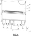
- the sheet 166 forming the rear face of the cabinet 100 comprises ventilation grilles 372, visible at the Figure 4 . These ventilation grilles are arranged opposite the ventilation zone 359 of each drawer.
- the ventilation zone 359 of a drawer 138 connects the interior of this drawer with the exterior of the cabinet, through these ventilation grilles 372. In such a configuration, the air circulating in the drawer 138 comes out directly outside the cabinet 100, through its rear face.
- the rear portion 348 of each drawer is located at the interface between the functional area 156, which includes the motor starter module 200, and the thermal management area 162.
- the ventilation area 359 connects the interior of the drawer 138 with the thermal management area 162 of the cabinet. In such a configuration, the air flow FL1 circulating in the drawer 138 emerges in the thermal management area 162 of the cabinet.
- the thermal management zone 162 is an essentially empty column, which extends over the entire height of the cabinet 100. Thus, the air leaving the drawers 138, heated by the functional elements 362 of these drawers, rises by convection to the top of the thermal management zone 162, just like the air leaving the communication module 134.
- the thermal management zone 162 comprises an upper face, at the top of the cabinet 100, which is in practice a part of the upper face F4 of the cabinet.
- This upper face comprises an exhaust grille, not shown.
- This exhaust grille allows hot air to exit the thermal management zone 162.
- an air flow FL2 coming from the drawers 138 and the communication module 134 rises through the thermal management zone 162 and exits from the top of the thermal management zone 162, i.e. through the upper face F4 of the cabinet 100, as shown in Figure 2 .
- the thermal management zone 162 has the role of a chimney for evacuating hot air coming from the drawers 138 and the communication module 134.
- the upper face of the thermal management zone which corresponds to the upper face F4 of the cabinet, comprises an extraction fan 374, which sucks in the air contained in the thermal management zone to discharge it outside the cabinet 100. Thanks to such a fan, the evacuation of the hot air flow FL2 is facilitated.
- the thermal management zone 162 which allows extraction of hot air from all of the drawers 138, as well as from the communication module 134, through the top of the cabinet 100, it is possible to install the cabinet 100 in such a way that its rear face is obstructed, for example by positioning the cabinet against a wall, or back-to-back with a second cabinet 100, without harming the thermal management of the drawers 138 and the communication module 134.
- Each drawer 138 comprises two movable lateral contacts 352, each arranged in a lateral structure 346.
- a first makes it possible to connect the drawer 138 to the communication interface 353 of the input-output module 206 and a second makes it possible to connect the drawer 138 to a communication interface 353 of the protection unit 140.
- the design and operation of these two movable lateral contacts are identical.
- each input-output module 206 comprises a communication interface 353 and the protection unit 140 comprises six communication interfaces 353, arranged in the windows 256.
- Each movable side contact 352 comprises a plate 404.
- the plate 404 comprises a main body 406 which is elongated along the Y axis and two fins 408 which extend perpendicular to the main body 406 along the X axis.
- the main body 406 has a height along the Z axis less than the height of the window 402 of the vertical wall 344.
- the plate 404 is arranged inside the drawer 138, in contact with the face of the vertical wall 344 directed towards the inside of the drawer 138.
- the two fins 408 of the plate extend outwardly from the drawer 138, are disposed in two slots 412 of the vertical wall 344 and extend between the vertical wall 344 and the side structure 346.
- Each fin includes an end edge 414, parallel to the Y axis and a chamfer 416, which connects the end edge 414 to the main body 406 of the insert 404.
- the vertical wall 344 comprises two holding brackets 418, which are located opposite the window 402 and formed by cutting and folding the vertical wall 344.
- the holding brackets 418 comprise a first part which extends perpendicular to the vertical wall 344 towards the inside of the drawer 138 and a second part which extends perpendicular to the first part, that is to say parallel to the vertical wall 344, so as to extend opposite the window 402.
- the plate 404 is held in position relative to the drawer 138 by the fins 408, arranged in the slots 412, by the brackets 418, which prevent the plate from translating towards the inside of the drawer 138 along the X axis, and by the vertical wall 344, which prevents the plate from translating towards the outside of the drawer along the X axis.
- the plate 404 is fixed relative to the drawer 138 along the Y axis.
- Each movable contact 352 also comprises a frame 422, disposed between the vertical wall 344 and the lateral structure 346.
- the lateral structure 346 comprises a main wall 424 and two secondary walls 426.
- the main wall 424 is parallel to the vertical wall 344 of the support plate 340 and the two secondary walls 426 extend from the main wall 424 towards the vertical wall 344, as visible for one of them at the Figure 15 .
- the lateral structure 346 defines an interior volume between the main 424 and secondary 426 walls and the vertical wall 344 of the support plate 340.
- the frame 422 is arranged inside the interior volume of the lateral structure 346 and is movable in this interior volume, along the Y axis.
- the frame 422 is not movable along the X axis because it is in contact on the one hand with the vertical wall 344 and on the other hand with the main wall 424.
- the height H422 of the frame 422 is less than the distance, measured along the Z axis, which separates the two secondary walls 426 of the lateral structure 346.
- the height of the frame 422 is greater than the height H400 of the window 400 of the side structure, so that the frame cannot exit the interior volume of the side structure through the window 400.
- the frame 422 comprises two openings 428 of height H428 which pass through the frame 422 along an axis parallel to the axis X.
- Each movable side contact 352 also includes a contact housing 430.
- the contact housing includes a frame 432 from which two contact carriers 434 extend, on each side of the frame 432, along the Y axis.
- each contact holder 434 denoted “H434”
- H434 The height of each contact holder 434, denoted “H434”, is less than the height H428 of the openings 428.
- the height of the frame 432 is greater than the height H428 of the openings 428.
- the contact housing 430 is arranged in the interior volume of the lateral structure 346, between the frame 422 and the vertical wall 344, and extends partially outside this interior volume, along the X axis, through the window 400.
- the frame 422 carries the contact housing 430.
- Each contact holder 434 passes through an opening 428 of the frame 422.
- the frame 422 guides the movement of the contact housing 430 along the Y axis in the side structure 346.
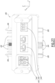
- a 650 computer bus connection is shown in figure 27 . This connection is also visible at the Figure 6 , assembled to a communication module 134.
- the computer bus connector 650 makes it possible to connect a computer bus section 204 of a connection column 110 to the communication module 134 of this connection column.
- each connection column 110 comprises a computer bus connector 650 fixed to the communication module 134 of the column.
- the computer bus connection 650 comprises male connectors 652 and female connectors 654, which are identical respectively to the male connectors 612 and the female connectors 622 of the computer bus section 204.
- the computer bus connector 650 also includes lugs 656 and cavities 658, which are identical to the lugs 620 and cavities 630 of the computer bus section 204, respectively.
- the computer bus connector 650 can be assembled on, and electrically connected to, a computer bus section, in the same manner that two computer bus sections can be assembled together, i.e. by fitting together.
- the computer bus 142 is formed by the assembly of a computer bus connector 650 and one or more computer bus sections 204.
- the computer bus section 204 can be equipped with jumpers 750.
- the male 752 and female 754 end jumpers make it possible to prevent the end of the computer bus 142 - which comprises several computer bus sections 204 assembled together - opposite the end connected to the computer bus connector 650 from being free in a motor starter column 110.
- a first end of the computer bus 142 is connected to the computer bus connector 650 and a second end of the computer bus is connected to a male 752 or female 754 end jumper.
- This connection makes it possible to protect the connectors 622 or 612 of the computer bus section 204 opposite the computer bus connection.
- the male end jumper 752 protects the female connectors 622 and the female end jumper 754 protects the male connectors 612.
- the male end jumper 752 comprises two lugs 758, of complementary shape to the cavities 630 of the first end of the computer bus section, and the female end jumper 754 comprises two cavities 760, of complementary shape to the lugs 620 of the second end of the computer bus section.
- end jumpers 752 and 754 make it possible to ensure the continuity of the electronic circuits 604 of the computer bus section 204, corresponding, in a motor start column 110, to the electronic circuits 144 of the computer bus 142.
- the electronic circuits 144 in particular when they allow an exchange of data according to the Ethernet protocol, connect the communication module 134 of an engine starter column 110 to the control-command drawers 138 in series.
- the electronic circuits 144 form a loop whose point of origin is the communication module 134.
- the end jumper 752 or 754 mounted on this free end makes it possible to close this loop, thanks to connectors connected to the electronic circuits 604, by being connected to the free end of the computer bus section.
- the male end jumper 752 comprises male connectors 762 and the female end jumper 754 comprises female connectors 764, which are identical respectively to the male connectors 612 and the female connectors 622 of the computer bus section 204.
- the engine starter column 110 does not include a communication module 134 and the electronic circuits 144 form a loop whose point of origin is the industrial computer 130, which then has a functional role identical to that of the communication module 134.
- these male 762 and female 764 connectors also make it possible to connect the end jumpers 752 and 754 to the power supply tracks 606 and 608.
- the power supply tracks 606 and 608 can supply the linear connectors 610 either in parallel or in series. Indeed, in the case of a series supply, the male 762 and female 764 end jumpers make it possible to close the loops of the power supply tracks 606 and 608.
- the input-output jumpers 756 make it possible to close the loop formed by the electronic circuits 144 at a given linear connector 610, when no input-output module 206 is connected to this linear connector 610.
- each 756 input-output jumper has a complementary 766 connector, configured to be connected to a 610 linear connector.
- This first verification method is advantageous because it makes it possible to ensure that a control-command drawer replacement is correctly carried out and makes it possible to carry out such a replacement without having to indicate operating parameters to the new control-command drawer, these operating parameters being automatically loaded.
- a data recovery method is carried out by the new communication module, which consists of recovering the operating parameters of the control-command drawers 138 and/or the information linked to the electrical charges 104 from the information recorded in the memory blocks 780 so that the new communication module 134 has this information.
- This method of data recovery is particularly advantageous because it avoids having to manually provide a large amount of data to the new communication module 134, which would be tedious, this data being automatically recovered here.
- this data recovery method applies in a similar manner to the replacement of the industrial computer 130.
- the fact that the memory blocks 780 are arranged on the computer bus sections 204 is particularly advantageous, because the computer bus sections are reliable elements, not prone to breakdowns, which are therefore generally not replaced during the lifetime of the electrical cabinet 100.
- the information recorded in these memory blocks 780 is not lost, even during complex maintenance operations in which, for example, a simultaneous replacement of control-command drawers 138, the associated input-output modules 206 and the communication module 134 would take place.
- connection of a drawer 138 to an electrical load 104 is carried out by means of an external connection module 208.
- an external connection module 208 is associated with each drawer 138.
- Each connection module of the module set 700 is configured to allow the connection of a drawer 138 to an electrical load 104 consuming an electrical power included in a given data range.
- a first external connection module 702 is shown in figures 28 And 29 This first connection module is configured to connect a drawer 138 to a low-power electrical load 104, for example less than 11 kW.
- a second external connection module 704 is shown in figures 30 And 31 This second connection module is configured to connect a drawer 138 to an electrical load 104 of average power, for example between 11 kW and 30 kW.
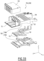
- a third external connection module 706 is shown in figures 32 And 33 This third connection module is configured to connect a drawer 138 to a high-power electrical load 104, for example between 30 kW and 75 kW.
- an external connection module to be installed on an engine starter module will depend on the electrical power required by the electrical load 104 connected to this module.
- the external connection modules 702, 704 and 706 each comprise a housing 708.
- the housing 708 comprises in practice two half-housings respectively forming a base 708A and a cover 708B, assembled by fixing means, such as screws 708C visible only for the external connection module 702 at the figure 29 .
- the 708 housing of the 702 external connection module has a height H702 equal to 1U.
- the 708 housing of the 704 external connection module has a height H704 equal to 2U.
- the 708 housing of the 706 external connection module has a height H706 equal to 3U.
- the external connection module 702 is associated with a drawer 138 of height 1U or 2U
- the external connection module 704 is associated with a drawer 138 of height 2U, 3U, 4U, 5U or 6U
- the external connection module 706 is associated with a drawer 138 of height 5U or 6U.
- the height of an external connection module is always less than or equal to the height of the drawer associated with it.
- a first end 709 of the housing 708 of each external connection module carries input connectors 710.
- the height of the first end 709 is equal to 1U, regardless of the height of the housing 708.
- a second end 711 of the housing 708 of each external connection module carries output connectors 712.
- the height of the second end 711 is equal to the height H702, H704 or H706 of the housing 708.
- the input 710 and output 712 connectors are arranged on the same face of the housing 708, that is to say that, when the housing is assembled on the engine starter module 200, the input 710 and output 712 connectors face the same face of the cabinet 100, in the example the front face F1.
- the first end 709 includes four input connectors and the second end includes four output connectors.
- the input connectors 710 are configured to be connected to the downstream connectors 356 of the drawer 138 associated with the connection module.
- the downstream connectors 356 of a drawer supply electrical energy to the external connection module 702, 704 or 706 associated with this drawer.
- the drawer 138 is a source of electricity for the connection module.
- the constant height of the first end 709 is advantageous because it is equal to the height of the base 328 of the drawer 138. A first end 709 then allows the connection of all the drawers 138, regardless of their height.
- the output connectors 712 are configured to be connected to the electrical load 104 via the connecting cables 139.
- connection cables 139 are connected to the output connectors 712 by terminals 716, as seen in the figure 29 .
- the input connectors 710 and the output connectors 712 are electrically connected by cables or conductive bars 718.
- the first and second external connection modules 702 and 704 taking into account the transmitted power, it is possible to use conductive cables between the connectors 710 and 712, these cables being represented by their respective center lines at figures 29 And 31
- connection bars visible at the figure 33 In the latter case, the connectors 710 and 712 are formed by the ends of the bars 718.
- each external connection module comprises four conductive cables or conductive bars 718, i.e. one bar per input connector and per output connector.
- the conductive cables or conductive bars 718 are adapted to the power consumed by the electrical load 104 connected to the output connectors 712.
- the conductive bars 718 are for example copper bars with a section between 16 and 50 mm 2 , for example equal to 50 mm 2 for an electrical load of 75 kW.
- the conductive cables 718 have a smaller cross-section, for example between 1 and 6 mm 2 , for example equal to 6 mm 2 for an electrical load of 11 kW.
- the conductive cables 718 of the first and second external connection modules 702 and 704 can be replaced by conductive bars.
- the third external connection module 706 has a height H706 greater than the height H704 of the second module 704, itself greater than the height H702 of the module 702.
- each external connection module further comprises a cover 720, which covers the output connectors 712.
- the connectors 712 are not accessible from outside the housing 708 and are therefore protected, which prevents any contact with the terminals 716.
- the connectors 712 are accessible, which allows the cables 139 to be connected to the connectors.
- the cover 720 is transparent, which makes it possible to check the correct connection of the cables 139 without making these cables accessible.
- the cover 720 is assembled to the housing 708 by fixing means, such as a screw 721 visible only for the external connection module 702.
- each external connection module is fixed to the rear support 210 of the structure 202 of the engine starter module 200, for example using screws, at its first end 709, that is to say at the end which comprises the input connectors 710.
- the housing 708 thus extends from the rear support 210 in a cantilevered manner, away from the engine starter module 200.
- each external connection module 704 and 706, i.e. of a 2U and 3U height module comprises a reinforcement 722, which extends from the housing 708 parallel to the first end 709 and which is also fixed to the rear support 210.
- the 722 reinforcement has a height equal to 1U. It is monobloc with the 708B cover.
- the first end 709, and possibly the reinforcement 722, are arranged in the volume V1 and in the functional zone 156 of the connecting column 110.
- the remainder of the housing 708 and the second end 711 extend into the wiring area 160 of the connection column 110.
- the functional area 156 and the wiring area 160 are separated by the side support 212 of the engine starter module.
- the first end 709 of an external connection module 702, 704 and 706 extends through the side support 212, and more particularly through an opening 220 provided in the lateral support 212.
- the reinforcement 722 of the housing 708 of an external connection module 704 and 706 also extends through an opening 220 of the side support 212.
- the external connection modules are configured so that the input 710 and output 712 connectors are arranged on two opposite faces. Such a configuration is advantageous when the connection of the cables 139 is carried out from the rear of the electrical cabinet 100, as in the variant of the Figure 5 .
- each drawer 138 comprises two centering members 800, arranged on the rear part 348 of the drawer and which extend along the Y axis outside the drawer.
- Each centering member 800 has a bevel shape, that is to say that its free end is less wide than its base attached to the rear part of the drawer, with which it is preferably in one piece.
- centering members 800 make it possible to guarantee correct positioning of the drawer 138 in the engine starter module 200 when it is moved to its operating position.
- the protection unit 140 comprises centering cavities 802 and each external connection module 702, 704 and 706 comprises a centering cavity 804.
- the centering cavities 802 of the protection unit 140 are arranged between the groups of connectors 246 and the inner face 238 of the protection unit 140, as visible in the Figure 11
- each external connection module 702, 704 and 706 are arranged on the cover 708B of each housing 708, near the first end 709 and the input connectors 710.
- the centering cavities 802 of the protection unit and 804 of each external connection module are directed towards the volume V1 of the engine starter module 200.
- the connections of the electrical loads 104 to the drawers 138 are moved from the functional area 156 to the wiring area 160. This is advantageous, because the wiring area 160 is easily accessible, which simplifies the connection of the electrical cables 139 to the output connectors 712.
- the number of types of external connection module 208 within the set of external connection modules may be other than three, in particular equal to 2, 4, 5 or 6.
- the main electrical power supplied by the power cable 102 is conducted into the electrical cabinet 100 first by the power column 106, then is redistributed to each protection unit 140 of each motor starter column 110 by the busbars 114, 118 and 122, then is redistributed to each drawer 138 by the connectors 248 and 354, then is redistributed to each external connection module 208 by the connectors 356, then is redistributed to each electrical load 104 by each external connection module 208.
- steps a) to e) may be different.
- steps b), c) and d) may be reversed and step a) may be carried out at any other time.
- step e) always comes after steps a) to c).
- the structure 202 of an engine starter module is firstly fixed to the frame 164 of the engine starter column, then step b) of assembling the engine starter module 200 is carried out.
- connection of the main power supply to the electrical loads 104 only requires the connection of the cables 139.
- the orientation of the elements included in an engine starter module 200 described above relates to an engine starter module arranged in a connection column located to the right of an electrical distribution column, on the figures 1 to 5 .
- the engine starter module 200 described above can also be arranged in a connection column located to the left of an electrical distribution column, on the figures 1 to 5 To do this, the engine starter module 200 is simply rotated 180 degrees around an axis parallel to the transverse Y axis.
- a motor starter module 200 has no preferred orientation: the protection unit 140, the computer bus section 204, each drawer 138, each input-output module 206 and each external connection module 208 are configured to operate independently of their spatial orientation.
- a drawer 138 of a connection column located to the left of an electrical distribution column will be arranged so that its base 328 is arranged at the top and its cover at the bottom. All the elements contained in a drawer 138 being fixed to the base 328, this arrangement does not impact the operation of the drawer. This arrangement also does not impact the cooling of the drawer by the air flow FL1, since the air flow FL1 is horizontal, and is therefore not affected by a change of orientation. Such an arrangement is visible at the Figure 1 .
- a communication module 134 has no preferred orientation and relative to the orientation described in this disclosure, a module installed in a connection column located to the left of an electrical distribution column will be rotated 180 degrees about an axis parallel to the transverse axis Y, as will the computer bus connector 650 attached thereto.
- the electronic control card 364 of a drawer 138 is configured to detect the orientation of the drawer 138, for example using a sensor integrated into the card, and to control the display 302 so that the information displayed there is oriented so as to be easily readable from outside the cabinet 100.
- the display 302 is therefore configured to adapt the orientation of the information displayed there to the orientation of the drawer 138.
- the electrical cabinet 100 does not include motor starter modules and the protection unit, the computer bus section, the control-command drawers, the input-output modules and the external connection modules are directly arranged in the electrical cabinet 100, fixed to the frame 164.
- a drawer 138 of height equal to 1U is shown without its cover 330.
- This drawer is similar to the drawer shown in figures 15 to 17 , but further comprises a position detection module 900 which is shown alone in the figure 43 .
- drawer 138 of the figures 41 And 42 similar to those of drawer 138 shown in figures 15 to 17 have the same references and operate in the same way.
- a component is mentioned in the following description of drawer 138 without being shown the figures 41 And 42 , it corresponds to the same element represented on the figures 1 to 40 .
- the position detection module 900 is fixed to the base 328 of the drawer 138.
- the position detection module 900 is fixed to one of the two side structures 346, preferably to the side structure which does not include the mechanical lock 820.
- the position detection module 900 is fixed to the same side structure as the mechanical lock 820.
- the position detection module 900 includes sensors for detecting when the drawer 138 is in the test position and for detecting when the drawer is in the operating position.
- the position detection module includes two sensors 902 and 904.
- the two sensors 902 and 904 are connected to the electronic control card 364, so as to transmit to the electronic control card information on the position of the drawer 138.
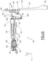
- the position detection module 900 also includes an actuator 906, provided to actuate the sensors 902 and 904.
- the actuator 906 is in the example a control rod.
- the control rod 906 includes a first end 908 and a second end 910.
- the first end 908 is fixed to the movable contact 352 of the lateral structure 346 on which the position detection module 900 is fixed. More precisely, the first end is fixed to the frame 422 of the movable contact 352. Thus, the first end 908 is integral with the frame 422 so that a translation of the frame 422 along the Y axis causes a translation of the control rod 906 along the Y axis, that is to say along the longitudinal axis A138 of the drawer. In other words, the control rod 906 is movable in translation relative to the lateral structure 346 along the longitudinal axis A138 of the drawer.
- the translation of the control rod 906 relative to the lateral structure 346 is advantageously guided by a fixed structure 912 of the position detection module 900, which notably comprises guides 914 at the level of the second end 910.
- the fixed structure 912 is fixed to the lateral structure 346, for example by screwing. Furthermore, in the example, the fixed structure 912 comprises two parts assembled between them, for example by riveting. At the figure 43 , the different parts of the fixed structure are identified by the same reference 912.
- the position detection module 900 comprises an elastic return member 916.
- the elastic return member 916 connects the fixed structure 912 to the control rod 906 so that, in the absence of other forces acting on the control rod, the control rod is returned to a position which corresponds to the position shown in FIG. figure 43 .
- the control rod 906 has a stable position, or rest position, which is that shown in the figure 43 , and the elastic return member 916 tends to bring the control rod back to this stable position.
- control rod 906 comprises a stop 917, which bears against the fixed structure 912 when the control rod is in the rest position, and which prevents movement of the control rod beyond its rest position.
- the stop 917 is formed of two tabs bent at right angles to the main part of the control rod.
- the elastic return member 916 is a traction spring, a first end of which is fixed to a hook 918 of the fixed structure 912 and a second end of which is fixed to the second end 910 of the control rod.
- control rod 906 is in the rest position when the drawer 138 is between its disconnected position and its engaged position, and the control rod moves along the axis A138 relative to the lateral structure 346 when the drawer is between its engaged position and its operating position, just like the frame 422.
- the position detection module 900 is oriented so that the second end 910 of the control rod 906 is located near the front portion 300 of the drawer 138 and so that the first end 908 is away from the front portion of the drawer.
- the second end 910 moves away from the sensors 902 and 904 and towards the front portion 300, until it is located in the front portion, extending through a window 919 provided in the fixed structure 912.
- an empty space is provided in the front portion 300 to accommodate the presence of the second end 910.
- the control rod 906 comprises two upper cams 920 and 922 and a lower cam 924.
- the two upper cams 920 and 922 are located in the same plane parallel to the axis A138, that is to say they are aligned along the Z axis, and are offset from the lower cam 924 along the Z axis.
- the upper cams 920 and 922 are provided to actuate the detector 902 and the lower cam 924 is provided to actuate the detector 904.
- the lengths L920, L922 and L924 have their respective maximum values when the control rod 906 is in the rest position, that is to say when the slide 138 is between its disconnected position and its engaged position.
- the lengths L922 and L924 are zero when the drawer 138 is in the operating position.
- the upper cam 922 is in contact with the actuating element 926 of the detector 902 and the lower cam 924 is in contact with the actuating element 928 of the detector 904, which simultaneously actuates the detectors 902 and 904 and causes two detection signals to be sent from the detectors 902 and 904 to the electronic control card 364, then informing the electronic control card that the drawer is in the operating position.
- the electronic control card 364 detects that the drawer 138 is in the test position when it simultaneously receives a signal from the detector 902 and the detector 904 actuated by the upper cam 922 and lower cam 924.
- the detectors 902 and 904 are dry contact switches and the actuating elements 926 and 928 are metal blades pivotally mounted around respective axes Z926 and Z928, parallel to the Z axis.
- the detector 902 is connected to the electronic control card 364 by two wires 930, shown in a simplified manner on the figures 41 to 43
- the two 930 wires form a loop starting and ending at the electronic control board, and passing by the detector 902 so that the metal blade 926 of the detector can open or close this loop.
- the loop formed by the two wires 930 is closed when the metal blade 926 is in contact with the high cam 920 or the high cam 922, because the high cams then push back the metal blade 926 by pivoting it around the axis Z926, and the loop is open when the metal blade is not in contact with a high cam.
- the electronic control card 364 receives a detection signal from the detector 902.
- the detector 904 is connected to the electronic control card 364 by two wires 932, shown in a simplified manner on the figures 41 to 43 , which form a loop which is closed when the metal blade 928 is in contact with the lower cam 924 and which is open when the metal blade is not in contact with the lower cam.
- the electronic control card 364 receives a detection signal from the detector 904.
- the electronic control card 364 is configured to detect that the drawer 138 is in the test position when a detection signal from the detector 902 is received, and to detect that the drawer 138 is in the operating position when detection signals from the detectors 902 and 904 are received simultaneously.
- the position detection module 900 is particularly advantageous, because it makes the operation of the drawer 138 more reliable. Indeed, thanks to the detection of the position of the drawer 138 provided by the position detection module 900, the control of the functional elements 362 by the electronic control card 364 takes into account the actual position of the drawer. The control of the functional elements 362 is then improved.
- the operation of the position detection module 900 is particularly reliable, because the position detection module is fully integrated into the drawer 138, and because the position of the drawer is detected only from the position of one of the movable side contacts 352, by detecting the position of this side contact relative to the base 328 of the drawer.
- the detection of the position of the drawer does not require interaction with a fixed structure of the motor starter module 200 or the electrical cabinet 100 and the position detection module 900 is isolated in the drawer 138.
- This is particularly advantageous, since the detection of the position of the drawer 138 is then insensitive to possible disturbances in the position of the drawer 138 relative to the electrical cabinet 100 around its test and operating positions, which could otherwise disturb the detectors 902 and 904. Such disturbances are, for example, caused by vibrations or by shocks suffered by the drawer.
- the operating position is detected when the electronic control card 364 receives only a detection signal from the detector 904.
- the control rod 906 does not include a second high cam 922, since actuation of the detector 902 in the operating position is not required.
- the orientation of the detectors 902 and 904 is different from the orientation shown in the figures 41 to 43 , and the position of the high cams 920 and 922 and low cams 924 is adapted accordingly.
- the position detection module 900 does not include an elastic return member 916.
- the return of the control rod 906 to its rest position is ensured by the traction springs 446, which tend to return the frame 422, and consequently the control rod, to the rest position.
- the detectors 902 and 904 are induction switches, or Hall effect switches detecting the position of the high cams 920 and 922 and low cams 924.
- the position detection module 900 comprises a single detector 902 or 904 for detecting the test and operating positions.
- the drawer 138 comprises movable contacts 352 which are movable only along the longitudinal axis A138 of the drawer.
- the communication interfaces 353 protrude, for example, from the input-output modules 206 and the protection units 140, so as to come into contact with the movable contacts 352 when the drawer 138 is in the test position, and to cause the movable contacts to move relative to the base 328 when the drawer is moved from its test position to its operating position.
- the operation of the position detection module 900 is unchanged.
Landscapes
- Engineering & Computer Science (AREA)
- Power Engineering (AREA)
- Automation & Control Theory (AREA)
- Microelectronics & Electronic Packaging (AREA)
- Patch Boards (AREA)
- Remote Monitoring And Control Of Power-Distribution Networks (AREA)
- Protection Of Static Devices (AREA)
Claims (9)
- Anschlussschaltschrank (100), wobei der Schaltschrank über Stromkabel (102) mit elektrischer Energie versorgt wird und konfiguriert ist, um mindestens eine elektrische Last (104) mit Strom zu versorgen, der Schaltschrank umfassend:• eine Versorgungssäule (106); und• - mindestens eine Anschlusssäule (110),wobei die Stromkabel (102) in der Stromsäule (106) an den Schaltschrank (100) angeschlossen sind,jede Anschlusssäule (110) umfassend mindestens eine Steuer- und Regeleinheit (138), die konfiguriert ist, um einen elektrischen Anschluss mit einer elektrischen Last (104) zu ermöglichen,wobei jede Steuer- und Regeleinheit (138) elektrisch durch eine Schutzeinheit (140) geschützt ist, die zu der Anschlusssäule dieser Steuer- und Regeleinheit gehört,wobei jede Steuer- und Regeleinheit (138) konfiguriert ist, um den Anschluss und gegebenenfalls die Steuerung und/oder Überwachung einer elektrischen Last (104) zu ermöglichen,wobei der Schaltschrank konfiguriert ist, um von einem Industriecomputer (130) gesteuert zu werden,jede Anschlusssäule (110) umfassend einKommunikationsmodul (134), das:• Betriebsinformationen von den Steuer- und Regeleinheiten (138) dieser Anschlusssäule zentralisiert;• konfiguriert ist, um diese Betriebsinformationen an den Industriecomputer (130) zu übertragen;• konfiguriert ist, um Befehle von dem Industriecomputer zu empfangen; und• diese Befehle an die Steuer- und Regeleinheiten dieser Anschlusssäule zu übertragen,dadurch gekennzeichnet, dass mindestens ein Kommunikationsmodul (134) einen Versorgungsblock(150) umfasst, der jeder Anschlusssäule (110) mindestens eine elektrische Hilfsspannung zuführt.
- Schaltschrank (100) nach Anspruch 1, dadurch gekennzeichnet, dass jede Anschlusssäule (110) einen Computerbus (142) umfasst, der das Kommunikationsmodul (134) dieser Anschlusssäule mit jeder Steuer- und Regeleinheit (138) dieser Anschlusssäule verbindet und der den Austausch von Informationen und Befehlen zwischen dem Kommunikationsmodul und jeder Steuer- und Regeleinheit dieser Anschlusssäule ermöglicht.
- Schaltschrank (100) nach Anspruch 2, dadurch gekennzeichnet, dass der Austausch von Informationen und Befehlen zwischen dem Kommunikationsmodul (134) einer Anschlusssäule (110) und jeder Einheit der Steuer- und Regeleinheit (138) dieser Säule über elektronische Schaltungen (144) des Computerbusses (142) verläuft und vorzugsweise gemäß dem Ethernet-Protokoll erfolgt.
- Schaltschrank (100) nach einem der Ansprüche 2 bis 3, dadurch gekennzeichnet, dass der Computerbus (142) jeder Anschlusssäule (110) Stromversorgungsbahnen (148, 154) umfasst, die konfiguriert sind, um jede Steuer- und Regeleinheit (138) dieser Anschlusssäule und/oder mindestens eine an diese Anschlusssäule angeschlossene elektrische Last (104) mit mindestens einer elektrischen Hilfsspannung zu versorgen.
- Schaltschrank (100) nach einem der vorherigen Ansprüche, dadurch gekennzeichnet, dassder Versorgungsblock (150) eine ersteelektrische Hilfsspannung an jede Steuer- und Regeleinheit (138) jeder Anschlusssäule (110) zuführt und konfiguriert ist, um eine zweite elektrische Hilfsspannung an mindestens eine elektrische Last (104) zuzuführen, die an eine Steuer- und Regeleinheit (138) angeschlossen ist.
- Schaltschrank (100) nach Anspruch 5, dadurch gekennzeichnet, dass die erste elektrische Hilfsspannung eine Gleichspannung von 48 V ist und die zweite elektrische Hilfsspannung eine Wechselspannung von 230 V ist.
- Schaltschrank (100) nach einem der vorhergehenden Ansprüche, dadurch gekennzeichnet, dass:• die Versorgungssäule (106) einen zentralen Schalter (137) umfasst;• der zentrale Schalter (137) zwischen dem Industriecomputer (130) und dem Kommunikationsmodul (134) jeder Anschlusssäule (110) angeschlossen ist, wobei:∘ der Zentralschalter (137) konfiguriert ist, um Befehle von dem Industriecomputer (130) zu empfangen und diese Befehle auf die Kommunikationsmodule (134) jeder Anschlusssäule zu verteilen; und∘ der Zentralschalter konfiguriert ist, um die Betriebsinformationen von den Kommunikationsmodulen jeder Anschlusssäule zu aggregieren und diese Informationen an den Industriecomputer zu übertragen.
- Schaltschrank (100) nach einem der vorherigen Ansprüche, umfassend mindestens zwei Anschlusssäulen (110), dadurch gekennzeichnet, dass:• das Kommunikationsmodul (134) jeder Anschlusssäule (110) einen gemanagten Switch (135) umfasst;• die gemanagten Switches (135) der Kommunikationsmodule (134) durch interne Kommunikationskabel (136) miteinander verbunden sind; und• jeder gemanagte Switch konfiguriert ist, um unabhängig von den anderen gemanagten Switches mit dem Industriecomputer (130) verbunden zu sein.
- Schaltschrank (100) nach einem der vorhergehenden Ansprüche, dadurch gekennzeichnet, dass alle Kabelanschlüsse an die Verbinder (192, 196, 198, 510, 660, 712) des Schaltschranks (100), die für die Inbetriebnahme des Schaltschranks erforderlich sind, in einem einzigen Anschlussbereich (158) realisiert werden.
Applications Claiming Priority (1)
| Application Number | Priority Date | Filing Date | Title |
|---|---|---|---|
| FR2103089A FR3121289B1 (fr) | 2021-03-26 | 2021-03-26 | Armoire électrique de raccordement |
Publications (2)
| Publication Number | Publication Date |
|---|---|
| EP4064475A1 EP4064475A1 (de) | 2022-09-28 |
| EP4064475B1 true EP4064475B1 (de) | 2025-07-02 |
Family
ID=75850350
Family Applications (1)
| Application Number | Title | Priority Date | Filing Date |
|---|---|---|---|
| EP22164291.1A Active EP4064475B1 (de) | 2021-03-26 | 2022-03-25 | Anschlussschrank |
Country Status (5)
| Country | Link |
|---|---|
| US (1) | US11690192B2 (de) |
| EP (1) | EP4064475B1 (de) |
| CN (1) | CN115133648A (de) |
| FR (1) | FR3121289B1 (de) |
| WO (1) | WO2022200555A1 (de) |
Families Citing this family (3)
| Publication number | Priority date | Publication date | Assignee | Title |
|---|---|---|---|---|
| FR3121314B1 (fr) * | 2021-03-26 | 2025-03-07 | Schneider Electric Ind Sas | Jeu de modules de raccordement externe pour armoire électrique de raccordement et armoire électrique de raccordement comprenant au moins un tel module de raccordement externe |
| FR3121291B1 (fr) * | 2021-03-26 | 2024-02-09 | Schneider Electric Ind Sas | Unité fonctionnelle pour armoire électrique de raccordement et armoire électrique de raccordement comprenant une telle unité fonctionnelle |
| CN116867200A (zh) * | 2023-07-12 | 2023-10-10 | 中国电建集团江西省电力设计院有限公司 | 一种变电站二次系统在线监测装置 |
Family Cites Families (18)
| Publication number | Priority date | Publication date | Assignee | Title |
|---|---|---|---|---|
| US5852795A (en) * | 1996-11-22 | 1998-12-22 | New York Gas Group | Apparatus for controlling a multiplicity of compressors |
| US5862338A (en) * | 1996-12-30 | 1999-01-19 | Compaq Computer Corporation | Polling system that determines the status of network ports and that stores values indicative thereof |
| US5958010A (en) * | 1997-03-20 | 1999-09-28 | Firstsense Software, Inc. | Systems and methods for monitoring distributed applications including an interface running in an operating system kernel |
| US6167437A (en) * | 1997-09-02 | 2000-12-26 | Silicon Graphics, Inc. | Method, system, and computer program product for page replication in a non-uniform memory access system |
| US6487091B2 (en) * | 1999-09-28 | 2002-11-26 | Rockwell Automation Technologies, Inc. | Method and apparatus for supplying data and power to panel-supported components |
| EP1143350A1 (de) * | 2000-04-03 | 2001-10-10 | Koninklijke KPN N.V. | Verfahren und System zum Wiederauffinden von Daten auf einem Datennetzwerk |
| US6871219B2 (en) * | 2001-03-07 | 2005-03-22 | Sun Microsystems, Inc. | Dynamic memory placement policies for NUMA architecture |
| DE102004062169A1 (de) * | 2004-12-17 | 2006-07-13 | Siemens Ag | Schaltanlage |
| US7661115B2 (en) * | 2006-01-30 | 2010-02-09 | International Business Machines Corporation | Method, apparatus and program storage device for preserving locked pages in memory when in user mode |
| FR2969404B1 (fr) * | 2010-12-16 | 2013-01-04 | Schneider Electric Ind Sas | Dispositif de communication et tableau electrique comportant un tel dispositif |
| US8810998B2 (en) * | 2012-04-23 | 2014-08-19 | Eaton Corporation | Motor control center and communication system therefor |
| JP6582367B2 (ja) * | 2014-07-18 | 2019-10-02 | 富士通株式会社 | 情報処理装置、情報処理装置の制御方法および情報処理装置の制御プログラム |
| DE102014111030B4 (de) * | 2014-08-04 | 2017-02-09 | Beckhoff Automation Gmbh | Koppeleinheit und industrielles Steuerungssystem |
| GB2552447B (en) * | 2016-04-06 | 2019-06-12 | Qhi Group Ltd | Fault monitoring systems and methods for detecting connectivity faults |
| US10452573B2 (en) * | 2016-12-06 | 2019-10-22 | Hewlett Packard Enterprise Development Lp | Scripted arbitration circuit |
| DE102018129835A1 (de) * | 2018-11-26 | 2020-05-28 | Beckhoff Automation Gmbh | Steuerungssystem, Kopplermodul und Verfahren zur Montage eines Steuerungssystems |
| US10739745B1 (en) * | 2019-03-27 | 2020-08-11 | Rockwell Automation Technologies, Inc. | Modular backplane for an industrial controller |
| US11553618B2 (en) * | 2020-08-26 | 2023-01-10 | PassiveLogic, Inc. | Methods and systems of building automation state load and user preference via network systems activity |
-
2021
- 2021-03-26 FR FR2103089A patent/FR3121289B1/fr active Active
-
2022
- 2022-03-18 US US17/698,308 patent/US11690192B2/en active Active
- 2022-03-25 EP EP22164291.1A patent/EP4064475B1/de active Active
- 2022-03-25 WO PCT/EP2022/057893 patent/WO2022200555A1/fr not_active Ceased
- 2022-03-28 CN CN202210311444.1A patent/CN115133648A/zh active Pending
Also Published As
| Publication number | Publication date |
|---|---|
| WO2022200555A1 (fr) | 2022-09-29 |
| FR3121289B1 (fr) | 2023-06-30 |
| US11690192B2 (en) | 2023-06-27 |
| EP4064475A1 (de) | 2022-09-28 |
| US20220312617A1 (en) | 2022-09-29 |
| CN115133648A (zh) | 2022-09-30 |
| FR3121289A1 (fr) | 2022-09-30 |
Similar Documents
| Publication | Publication Date | Title |
|---|---|---|
| EP4064476B1 (de) | Funktionsmodul für anschlussschrank, anschlussschrank mit einem solchen modul, verfahren zur prüfung und verfahren zur wiederherstellung von daten, die von einem solchen anschlussschrank ausgeführt werden | |
| EP4064474B1 (de) | Einschub zur laststeuerung für anschlussschrank und anschlussschrank, der einen solchen einschub umfasst | |
| EP4064475B1 (de) | Anschlussschrank | |
| EP4064472B1 (de) | Modularer steuerungseinschub für anschlussschrank und anschlussschrank, der einen solchen modularen einschub umfasst | |
| EP4064480B1 (de) | Anschlussschrank, der mindestens ein modul für den externen anschluss aus einem modulsatz umfasst | |
| EP4064473B1 (de) | Funktionsmodul für anschlussschrank und anschlussschrank, der ein solches funktionsmodul umfasst | |
| EP4064478B1 (de) | Steuerungseinschub für anschlussschrank und anschlussschrank, der einen solchen steuerungseinschub umfasst | |
| EP4064477B1 (de) | Steuerungseinschub für anschlussschrank und anschlussschrank, der einen solchen steuerungseinschub umfasst | |
| FR3108800A1 (fr) | Dispositif electrique pour l’alimentation electrique d’appareils electriques de puissance | |
| WO2023237738A1 (fr) | Armoire électrique de raccordement | |
| EP4199020B1 (de) | Schutzeinheit für steuer- und bedieneinheiten eines schaltschranks |
Legal Events
| Date | Code | Title | Description |
|---|---|---|---|
| PUAI | Public reference made under article 153(3) epc to a published international application that has entered the european phase |
Free format text: ORIGINAL CODE: 0009012 |
|
| STAA | Information on the status of an ep patent application or granted ep patent |
Free format text: STATUS: THE APPLICATION HAS BEEN PUBLISHED |
|
| AK | Designated contracting states |
Kind code of ref document: A1 Designated state(s): AL AT BE BG CH CY CZ DE DK EE ES FI FR GB GR HR HU IE IS IT LI LT LU LV MC MK MT NL NO PL PT RO RS SE SI SK SM TR |
|
| STAA | Information on the status of an ep patent application or granted ep patent |
Free format text: STATUS: REQUEST FOR EXAMINATION WAS MADE |
|
| 17P | Request for examination filed |
Effective date: 20230228 |
|
| RBV | Designated contracting states (corrected) |
Designated state(s): AL AT BE BG CH CY CZ DE DK EE ES FI FR GB GR HR HU IE IS IT LI LT LU LV MC MK MT NL NO PL PT RO RS SE SI SK SM TR |
|
| GRAP | Despatch of communication of intention to grant a patent |
Free format text: ORIGINAL CODE: EPIDOSNIGR1 |
|
| STAA | Information on the status of an ep patent application or granted ep patent |
Free format text: STATUS: GRANT OF PATENT IS INTENDED |
|
| RIC1 | Information provided on ipc code assigned before grant |
Ipc: H02B 1/20 20060101ALN20250219BHEP Ipc: H02J 13/00 20060101ALI20250219BHEP Ipc: H02B 11/10 20060101ALI20250219BHEP Ipc: H02B 1/36 20060101AFI20250219BHEP |
|
| INTG | Intention to grant announced |
Effective date: 20250303 |
|
| GRAS | Grant fee paid |
Free format text: ORIGINAL CODE: EPIDOSNIGR3 |
|
| GRAA | (expected) grant |
Free format text: ORIGINAL CODE: 0009210 |
|
| STAA | Information on the status of an ep patent application or granted ep patent |
Free format text: STATUS: THE PATENT HAS BEEN GRANTED |
|
| AK | Designated contracting states |
Kind code of ref document: B1 Designated state(s): AL AT BE BG CH CY CZ DE DK EE ES FI FR GB GR HR HU IE IS IT LI LT LU LV MC MK MT NL NO PL PT RO RS SE SI SK SM TR |
|
| REG | Reference to a national code |
Ref country code: GB Ref legal event code: FG4D Free format text: NOT ENGLISH |
|
| REG | Reference to a national code |
Ref country code: CH Ref legal event code: EP |
|
| REG | Reference to a national code |
Ref country code: DE Ref legal event code: R096 Ref document number: 602022016677 Country of ref document: DE |
|
| REG | Reference to a national code |
Ref country code: IE Ref legal event code: FG4D Free format text: LANGUAGE OF EP DOCUMENT: FRENCH |
|
| REG | Reference to a national code |
Ref country code: NL Ref legal event code: MP Effective date: 20250702 |
|
| PG25 | Lapsed in a contracting state [announced via postgrant information from national office to epo] |
Ref country code: PT Free format text: LAPSE BECAUSE OF FAILURE TO SUBMIT A TRANSLATION OF THE DESCRIPTION OR TO PAY THE FEE WITHIN THE PRESCRIBED TIME-LIMIT Effective date: 20251103 |
|
| PG25 | Lapsed in a contracting state [announced via postgrant information from national office to epo] |
Ref country code: NL Free format text: LAPSE BECAUSE OF FAILURE TO SUBMIT A TRANSLATION OF THE DESCRIPTION OR TO PAY THE FEE WITHIN THE PRESCRIBED TIME-LIMIT Effective date: 20250702 |
|
| REG | Reference to a national code |
Ref country code: AT Ref legal event code: MK05 Ref document number: 1810379 Country of ref document: AT Kind code of ref document: T Effective date: 20250702 |
|
| PG25 | Lapsed in a contracting state [announced via postgrant information from national office to epo] |
Ref country code: IS Free format text: LAPSE BECAUSE OF FAILURE TO SUBMIT A TRANSLATION OF THE DESCRIPTION OR TO PAY THE FEE WITHIN THE PRESCRIBED TIME-LIMIT Effective date: 20251102 |
|
| PG25 | Lapsed in a contracting state [announced via postgrant information from national office to epo] |
Ref country code: NO Free format text: LAPSE BECAUSE OF FAILURE TO SUBMIT A TRANSLATION OF THE DESCRIPTION OR TO PAY THE FEE WITHIN THE PRESCRIBED TIME-LIMIT Effective date: 20251002 |
|
| REG | Reference to a national code |
Ref country code: LT Ref legal event code: MG9D |
|
| PG25 | Lapsed in a contracting state [announced via postgrant information from national office to epo] |
Ref country code: AT Free format text: LAPSE BECAUSE OF FAILURE TO SUBMIT A TRANSLATION OF THE DESCRIPTION OR TO PAY THE FEE WITHIN THE PRESCRIBED TIME-LIMIT Effective date: 20250702 |
|
| PG25 | Lapsed in a contracting state [announced via postgrant information from national office to epo] |
Ref country code: FI Free format text: LAPSE BECAUSE OF FAILURE TO SUBMIT A TRANSLATION OF THE DESCRIPTION OR TO PAY THE FEE WITHIN THE PRESCRIBED TIME-LIMIT Effective date: 20250702 |
|
| PG25 | Lapsed in a contracting state [announced via postgrant information from national office to epo] |
Ref country code: HR Free format text: LAPSE BECAUSE OF FAILURE TO SUBMIT A TRANSLATION OF THE DESCRIPTION OR TO PAY THE FEE WITHIN THE PRESCRIBED TIME-LIMIT Effective date: 20250702 |
|
| PG25 | Lapsed in a contracting state [announced via postgrant information from national office to epo] |
Ref country code: GR Free format text: LAPSE BECAUSE OF FAILURE TO SUBMIT A TRANSLATION OF THE DESCRIPTION OR TO PAY THE FEE WITHIN THE PRESCRIBED TIME-LIMIT Effective date: 20251003 |
|
| PG25 | Lapsed in a contracting state [announced via postgrant information from national office to epo] |
Ref country code: SE Free format text: LAPSE BECAUSE OF FAILURE TO SUBMIT A TRANSLATION OF THE DESCRIPTION OR TO PAY THE FEE WITHIN THE PRESCRIBED TIME-LIMIT Effective date: 20250702 Ref country code: CZ Free format text: LAPSE BECAUSE OF FAILURE TO SUBMIT A TRANSLATION OF THE DESCRIPTION OR TO PAY THE FEE WITHIN THE PRESCRIBED TIME-LIMIT Effective date: 20250702 |
|
| PG25 | Lapsed in a contracting state [announced via postgrant information from national office to epo] |
Ref country code: LV Free format text: LAPSE BECAUSE OF FAILURE TO SUBMIT A TRANSLATION OF THE DESCRIPTION OR TO PAY THE FEE WITHIN THE PRESCRIBED TIME-LIMIT Effective date: 20250702 |
|
| PG25 | Lapsed in a contracting state [announced via postgrant information from national office to epo] |
Ref country code: BG Free format text: LAPSE BECAUSE OF FAILURE TO SUBMIT A TRANSLATION OF THE DESCRIPTION OR TO PAY THE FEE WITHIN THE PRESCRIBED TIME-LIMIT Effective date: 20250702 Ref country code: PL Free format text: LAPSE BECAUSE OF FAILURE TO SUBMIT A TRANSLATION OF THE DESCRIPTION OR TO PAY THE FEE WITHIN THE PRESCRIBED TIME-LIMIT Effective date: 20250702 |
|
| PG25 | Lapsed in a contracting state [announced via postgrant information from national office to epo] |
Ref country code: RS Free format text: LAPSE BECAUSE OF FAILURE TO SUBMIT A TRANSLATION OF THE DESCRIPTION OR TO PAY THE FEE WITHIN THE PRESCRIBED TIME-LIMIT Effective date: 20251002 |
|
| PG25 | Lapsed in a contracting state [announced via postgrant information from national office to epo] |
Ref country code: ES Free format text: LAPSE BECAUSE OF FAILURE TO SUBMIT A TRANSLATION OF THE DESCRIPTION OR TO PAY THE FEE WITHIN THE PRESCRIBED TIME-LIMIT Effective date: 20250702 |