EP4064466A1 - Flexible sliding power supply assembly, massage cushion, and control method therefor - Google Patents
Flexible sliding power supply assembly, massage cushion, and control method therefor Download PDFInfo
- Publication number
- EP4064466A1 EP4064466A1 EP21904616.6A EP21904616A EP4064466A1 EP 4064466 A1 EP4064466 A1 EP 4064466A1 EP 21904616 A EP21904616 A EP 21904616A EP 4064466 A1 EP4064466 A1 EP 4064466A1
- Authority
- EP
- European Patent Office
- Prior art keywords
- conductive
- massage
- flexible
- sliding
- rail
- Prior art date
- Legal status (The legal status is an assumption and is not a legal conclusion. Google has not performed a legal analysis and makes no representation as to the accuracy of the status listed.)
- Granted
Links
Images



Classifications
-
- A—HUMAN NECESSITIES
- A61—MEDICAL OR VETERINARY SCIENCE; HYGIENE
- A61H—PHYSICAL THERAPY APPARATUS, e.g. DEVICES FOR LOCATING OR STIMULATING REFLEX POINTS IN THE BODY; ARTIFICIAL RESPIRATION; MASSAGE; BATHING DEVICES FOR SPECIAL THERAPEUTIC OR HYGIENIC PURPOSES OR SPECIFIC PARTS OF THE BODY
- A61H15/00—Massage by means of rollers, balls, e.g. inflatable, chains, or roller chains
- A61H15/0078—Massage by means of rollers, balls, e.g. inflatable, chains, or roller chains power-driven
-
- H—ELECTRICITY
- H01—ELECTRIC ELEMENTS
- H01R—ELECTRICALLY-CONDUCTIVE CONNECTIONS; STRUCTURAL ASSOCIATIONS OF A PLURALITY OF MUTUALLY-INSULATED ELECTRICAL CONNECTING ELEMENTS; COUPLING DEVICES; CURRENT COLLECTORS
- H01R41/00—Non-rotary current collectors for maintaining contact between moving and stationary parts of an electric circuit
-
- A—HUMAN NECESSITIES
- A61—MEDICAL OR VETERINARY SCIENCE; HYGIENE
- A61H—PHYSICAL THERAPY APPARATUS, e.g. DEVICES FOR LOCATING OR STIMULATING REFLEX POINTS IN THE BODY; ARTIFICIAL RESPIRATION; MASSAGE; BATHING DEVICES FOR SPECIAL THERAPEUTIC OR HYGIENIC PURPOSES OR SPECIFIC PARTS OF THE BODY
- A61H1/00—Apparatus for passive exercising; Vibrating apparatus; Chiropractic devices, e.g. body impacting devices, external devices for briefly extending or aligning unbroken bones
-
- A—HUMAN NECESSITIES
- A61—MEDICAL OR VETERINARY SCIENCE; HYGIENE
- A61H—PHYSICAL THERAPY APPARATUS, e.g. DEVICES FOR LOCATING OR STIMULATING REFLEX POINTS IN THE BODY; ARTIFICIAL RESPIRATION; MASSAGE; BATHING DEVICES FOR SPECIAL THERAPEUTIC OR HYGIENIC PURPOSES OR SPECIFIC PARTS OF THE BODY
- A61H7/00—Devices for suction-kneading massage; Devices for massaging the skin by rubbing or brushing not otherwise provided for
-
- G—PHYSICS
- G05—CONTROLLING; REGULATING
- G05B—CONTROL OR REGULATING SYSTEMS IN GENERAL; FUNCTIONAL ELEMENTS OF SUCH SYSTEMS; MONITORING OR TESTING ARRANGEMENTS FOR SUCH SYSTEMS OR ELEMENTS
- G05B19/00—Program-control systems
- G05B19/02—Program-control systems electric
- G05B19/04—Program control other than numerical control, i.e. in sequence controllers or logic controllers
- G05B19/042—Program control other than numerical control, i.e. in sequence controllers or logic controllers using digital processors
-
- A—HUMAN NECESSITIES
- A61—MEDICAL OR VETERINARY SCIENCE; HYGIENE
- A61H—PHYSICAL THERAPY APPARATUS, e.g. DEVICES FOR LOCATING OR STIMULATING REFLEX POINTS IN THE BODY; ARTIFICIAL RESPIRATION; MASSAGE; BATHING DEVICES FOR SPECIAL THERAPEUTIC OR HYGIENIC PURPOSES OR SPECIFIC PARTS OF THE BODY
- A61H2201/00—Characteristics of apparatus not provided for in the preceding codes
- A61H2201/01—Constructive details
- A61H2201/0107—Constructive details modular
-
- A—HUMAN NECESSITIES
- A61—MEDICAL OR VETERINARY SCIENCE; HYGIENE
- A61H—PHYSICAL THERAPY APPARATUS, e.g. DEVICES FOR LOCATING OR STIMULATING REFLEX POINTS IN THE BODY; ARTIFICIAL RESPIRATION; MASSAGE; BATHING DEVICES FOR SPECIAL THERAPEUTIC OR HYGIENIC PURPOSES OR SPECIFIC PARTS OF THE BODY
- A61H2201/00—Characteristics of apparatus not provided for in the preceding codes
- A61H2201/01—Constructive details
- A61H2201/0119—Support for the device
- A61H2201/0134—Cushion or similar support
-
- A—HUMAN NECESSITIES
- A61—MEDICAL OR VETERINARY SCIENCE; HYGIENE
- A61H—PHYSICAL THERAPY APPARATUS, e.g. DEVICES FOR LOCATING OR STIMULATING REFLEX POINTS IN THE BODY; ARTIFICIAL RESPIRATION; MASSAGE; BATHING DEVICES FOR SPECIAL THERAPEUTIC OR HYGIENIC PURPOSES OR SPECIFIC PARTS OF THE BODY
- A61H2201/00—Characteristics of apparatus not provided for in the preceding codes
- A61H2201/01—Constructive details
- A61H2201/0119—Support for the device
- A61H2201/0138—Support for the device incorporated in furniture
-
- A—HUMAN NECESSITIES
- A61—MEDICAL OR VETERINARY SCIENCE; HYGIENE
- A61H—PHYSICAL THERAPY APPARATUS, e.g. DEVICES FOR LOCATING OR STIMULATING REFLEX POINTS IN THE BODY; ARTIFICIAL RESPIRATION; MASSAGE; BATHING DEVICES FOR SPECIAL THERAPEUTIC OR HYGIENIC PURPOSES OR SPECIFIC PARTS OF THE BODY
- A61H2201/00—Characteristics of apparatus not provided for in the preceding codes
- A61H2201/12—Driving means
- A61H2201/1207—Driving means with electric or magnetic drive
-
- A—HUMAN NECESSITIES
- A61—MEDICAL OR VETERINARY SCIENCE; HYGIENE
- A61H—PHYSICAL THERAPY APPARATUS, e.g. DEVICES FOR LOCATING OR STIMULATING REFLEX POINTS IN THE BODY; ARTIFICIAL RESPIRATION; MASSAGE; BATHING DEVICES FOR SPECIAL THERAPEUTIC OR HYGIENIC PURPOSES OR SPECIFIC PARTS OF THE BODY
- A61H2201/00—Characteristics of apparatus not provided for in the preceding codes
- A61H2201/16—Physical interface with patient
- A61H2201/1657—Movement of interface, i.e. force application means
- A61H2201/1664—Movement of interface, i.e. force application means linear
- A61H2201/1669—Movement of interface, i.e. force application means linear moving along the body in a reciprocating manner
-
- A—HUMAN NECESSITIES
- A61—MEDICAL OR VETERINARY SCIENCE; HYGIENE
- A61H—PHYSICAL THERAPY APPARATUS, e.g. DEVICES FOR LOCATING OR STIMULATING REFLEX POINTS IN THE BODY; ARTIFICIAL RESPIRATION; MASSAGE; BATHING DEVICES FOR SPECIAL THERAPEUTIC OR HYGIENIC PURPOSES OR SPECIFIC PARTS OF THE BODY
- A61H7/00—Devices for suction-kneading massage; Devices for massaging the skin by rubbing or brushing not otherwise provided for
- A61H7/002—Devices for suction-kneading massage; Devices for massaging the skin by rubbing or brushing not otherwise provided for by rubbing or brushing
- A61H7/004—Devices for suction-kneading massage; Devices for massaging the skin by rubbing or brushing not otherwise provided for by rubbing or brushing power-driven, e.g. electrical
-
- G—PHYSICS
- G16—INFORMATION AND COMMUNICATION TECHNOLOGY [ICT] SPECIALLY ADAPTED FOR SPECIFIC APPLICATION FIELDS
- G16H—HEALTHCARE INFORMATICS, i.e. INFORMATION AND COMMUNICATION TECHNOLOGY [ICT] SPECIALLY ADAPTED FOR THE HANDLING OR PROCESSING OF MEDICAL OR HEALTHCARE DATA
- G16H20/00—ICT specially adapted for therapies or health-improving plans, e.g. for handling prescriptions, for steering therapy or for monitoring patient compliance
- G16H20/30—ICT specially adapted for therapies or health-improving plans, e.g. for handling prescriptions, for steering therapy or for monitoring patient compliance relating to physical therapies or activities, e.g. physiotherapy, acupressure or exercising
-
- H—ELECTRICITY
- H01—ELECTRIC ELEMENTS
- H01R—ELECTRICALLY-CONDUCTIVE CONNECTIONS; STRUCTURAL ASSOCIATIONS OF A PLURALITY OF MUTUALLY-INSULATED ELECTRICAL CONNECTING ELEMENTS; COUPLING DEVICES; CURRENT COLLECTORS
- H01R2201/00—Connectors or connections adapted for particular applications
- H01R2201/12—Connectors or connections adapted for particular applications for medicine and surgery
-
- H—ELECTRICITY
- H01—ELECTRIC ELEMENTS
- H01R—ELECTRICALLY-CONDUCTIVE CONNECTIONS; STRUCTURAL ASSOCIATIONS OF A PLURALITY OF MUTUALLY-INSULATED ELECTRICAL CONNECTING ELEMENTS; COUPLING DEVICES; CURRENT COLLECTORS
- H01R25/00—Coupling parts adapted for simultaneous co-operation with two or more identical counterparts, e.g. for distributing energy to two or more circuits
- H01R25/14—Rails or bus-bars constructed so that the counterparts can be connected thereto at any point along their length
- H01R25/142—Their counterparts
-
- H—ELECTRICITY
- H01—ELECTRIC ELEMENTS
- H01R—ELECTRICALLY-CONDUCTIVE CONNECTIONS; STRUCTURAL ASSOCIATIONS OF A PLURALITY OF MUTUALLY-INSULATED ELECTRICAL CONNECTING ELEMENTS; COUPLING DEVICES; CURRENT COLLECTORS
- H01R25/00—Coupling parts adapted for simultaneous co-operation with two or more identical counterparts, e.g. for distributing energy to two or more circuits
- H01R25/14—Rails or bus-bars constructed so that the counterparts can be connected thereto at any point along their length
- H01R25/147—Low voltage devices, i.e. safe to touch live conductors
Definitions
- the present disclosure relates to the field of massagers, specifically to a flexible sliding powers supply assembly, and a massage cushion and a control method therefor.
- a massager belongs to a kind of conventional health care equipment.
- the massager has several soft-touch massage heads, which can relax muscles, soothe nerves, promote blood circulation, relieve fatigue, significantly reduce various chronic pains, acute pains and muscle soreness, relax the body and reduce stress.
- a massage cushion is convenient to install and use, and is widely used in automobiles seats, office chairs, or sofas.
- the massage cushion needs to be customized according to the shape of a seat, so that the development cost is high and the development period is long.
- a guide rail may be prone to problems such as intermittent poor contact and derailment.
- the existing massage cushion is usually provided with multiple groups of movements.
- a power supply main board is controlled to be connected to power or communicate with the multiple groups of movements, each connected movement is connected by one wire, resulting in that more movements require move wires, so that the machining difficulty is high, and the assembling and maintenance cost is high.
- the first manner is wire connection.
- a wire can be bent to be folded and unfolded.
- the massage movement cannot effectively avoid a position where a person can squeeze, so that after the wire is squeezed by an external force and the person, the moving trajectory will change, or the wire cannot be bent and unfolded, which makes the wire broken or twined on a massage head.
- a product malfunctions, and frequent folding and unfolding of the wire will cause a copper wire inside the wire to be broken.
- the second manner is spring-shape wire connection.
- a spring-shape wire is spiral, the diameter of the wire will increase.
- the spring-shape wire will be easily squeezed by a person, causing a malfunction.
- the spring-shape wire is frequently stretched and bent, a copper wire in it will also be broken.
- the third manner is fixed conductive guide rail connection.
- this conductive connection method special conductive guide rails need to be customized and designed for each kind of massage chairs with different shapes, and a special mold needs to be opened.
- a fixed conductive guide rail occupies a large space, has high development cost, and long development period.
- the present disclosure aims to provide a flexible sliding power supply assembly with stable structure, good contact and low manufacturing cost, and a massage cushion and a control method therefor.
- a flexible sliding power supply assembly includes a flexible conductive rail and a sliding conductive assembly.
- the flexible conductive rail is provided with two or more fixing slots, and conductive bars are mounted in the fixing slots in an embedded manner.
- the sliding conductive assembly is mounted on the flexible conductive rail; the sliding conductive assembly is in slidably electric connection with the conductive bars; and the conductive bars are correspondingly electrically connected to a power supply and a controller.
- the sliding conductive assembly includes a probe control sleeve, conductive probes, and a circuit board; the circuit board is mounted in the probe control sleeve; and the circuit board is electrically connected with a plurality of conductive probes.
- the middle part of the probe control sleeve is a connecting opening; by the connecting opening, the probe control sleeve is capable of being mounted on the flexible conductive rail; and the conductive probes protrude from the connecting opening and are electrically connected to the conductive bars on the flexible conductive rail.
- one side of the probe control sleeve is provided with a connecting part fixedly connected to a massage movement; and each conductive bar is correspondingly electrically connected to one or more conductive probes.
- Each conductive probe is formed by combining a copper pin, a spring and a wire.
- one or more magnets are mounted on a flexible conductive rail in an embedded manner; a hall switch is mounted on the circuit board of the massage movement; and the hall switch can determine the position of the movement by sensing a magnetic field formed by the magnets.
- the fixing slots are " "-shaped; each fixing slot includes a fixed part and an opening part; a width and thickness of the fixed part are both equal to those of each conductive bar; a width of the opening part is less than that of the conductive bar; and a thickness of the opening part is less than an extending height of the conductive probe.
- a massage cushion adopts the flexible sliding power supply assembly.
- the flexible conductive rail is fixedly mounted on a cushion body; the other side of the cushion body is further provided with a rack; and one or more massage movements are mounted between the flexible conductive rail and the rack.
- each massage movement is meshed with the rack; the other side of the massage movement is fixedly provided with the sliding conductive assembly; and the massage movement is electrically connected with each conductive bar through the sliding conductive assembly.
- the fixing slots of the flexible conductive rail are inwardly disposed; the circuit board of the probe control sleeve and one side of each conductive probe is inwardly disposed; and a massage head on each massage movement is outwardly disposed.
- An upper surface and a lower surface of the probe control sleeve are both of arc curved structures.
- a control method is applied to a massage cushion.
- the flexible conductive rail is provided with three conductive bars; two conductive bars are used for supplying power, and the third conductive bar is used for controlling signals; the conductive bars are also electrically connected with a controller; the circuit board is also electrically connected with a micro control unit (MCU); and the control method specifically includes the following steps:
- control method further includes step S3, positioning: sensing, by the MCU, a magnet on a flexible conductive rail of the cushion body through the hall switch on the circuit board; after the MCU determines the position of the massage movement, encoding, by the MCU, position information; transmitting the encoded position information to the controller via a specified conductive bar; and decoding, by the CPU on the controller, the encoded position information to obtain the position information of the massage movement.
- the present disclosure has the beneficial effects.
- the flexible conductive rail in the sliding power supply assembly of the present disclosure is made of high-toughness engineering plastic.
- the flexible conductive rail can bend in a large arc in one direction to adapt to massage chairs with different shapes, so that the adaptability is good, and it can be used for both a common cushion and a curved cushion.
- the tunnel type sliding conductive assembly can be made to be a standard component, thus adapting to various kinds of cushions, reducing the development cost, facilitating the assembling, reducing the kinds of materials, and decreasing the product cost.
- the flexible conductive rail is connected by the tunnel type probe control sleeve structure, so that reliable fixing is achieved during sliding guidance, and the problem of derailment is completely solved.
- Each conductive bar corresponds to two conductive probes.
- the parallel conductive probes have good contact-conducting stability, so that the problem of poor contact easily caused in the existing fixed conductive rail is solved.
- one controller can be connected to a plurality of massage movements with the tunnel type sliding conductive assemblies by only three conductive bars, so that the number of wires is reduced, and the problems of breakage of wires of the massage cushion and twining of the wires on a massage head are completely solved.
- the flexible conductive rail has a normative appearance and a compact structure, and the moving trajectory can be fixed according to the movement.
- the sliding conductive assembly is located on a side surface.
- One protruding end of the circuit board of the sliding conductive assembly is located on an inner side, and at the same time, the upper and lower end parts of the sliding conductive assembly are both arc-shaped, so that a position where a person easily squeezes can be bypassed; a product has more stable quality; and the person feels more comfortable during massage.
- a specific embodiment of the present disclosure is a flexible sliding power supply assembly, including a flexible conductive rail 1 and a sliding conductive assembly 3.
- the flexible conductive rail 1 is provided with two or more fixing slots 4, and conductive bars 2 are mounted in the fixing slots 4 in an embedded manner.
- a sliding conductive assembly 3 is mounted on the flexible conductive rail 1; the sliding conductive assembly 3 is in slidably electric connection with the conductive bars 2; and the conductive bars 2 are correspondingly electrically connected to a power supply and a controller 9.
- the sliding conductive assembly 3 includes a probe control sleeve 301, conductive probes 302, and a circuit board 303; the circuit board 303 is mounted in the probe control sleeve 301; and the circuit board 303 is electrically connected with a plurality of conductive probes 302.
- the probe control sleeve of the present disclosure is of a tunnel type structure.
- the tunnel type probe control sleeve can ensure that an assembly will not be loosened and fall off from the flexible conductive rail and can also ensure that the conductive probes are always kept in a stable electric connection state during vibration. During use, under squeezing, the probe control sleeve can also move with the flexible conductive rail to keep the stable electric connection.
- the traditional conductive rail adopts a rigid rail, which cannot adapt to a vibration environment of a massager and a squeezed usage scenario.
- the middle part of the probe control sleeve 301 is a connecting opening 304; by the connecting opening 304, the probe control sleeve can be mounted on the flexible conductive rail 1; and the conductive probes 302 protrude from the connecting opening 304 and are electrically connected to the conductive bars 2 on the flexible conductive rail 1.
- Each conductive probe 302 is formed by combining a copper pin, a wire and a spring. Meanwhile, a plurality of conductive probes can enlarge a contact area, which can meet a requirement for high current.
- One or more magnets 6 are mounted on an operating rail of the massage movement 5 on a back shell of a cushion body in an embedded manner; a hall switch is mounted on the circuit board of the massage movement 5; and the hall switch can determine the position of the movement by sensing a magnetic field formed by the magnets 6.
- the fixing slots 4 are " "-shaped; each fixing slot 4 includes a fixed part 401 and an opening part 402; a width and thickness of the fixed part 401 are both equal to those of each conductive bar 2; a width of the opening part 402 is less than that of the conductive bar 2; and a thickness of the opening part 402 is less than an extending height of the copper pin.
- a massage cushion adopts the flexible sliding power supply assembly.
- the flexible conductive rail is fixedly mounted on a cushion body 8; the other side of the cushion body 8 is further provided with a rack 7; and one or more massage movements 5 are mounted between the flexible conductive rail 1 and the rack 7.
- each massage movement 5 is meshed with the rack 7; the other side of the massage movement 5 is fixedly provided with the sliding assembly 3; and the massage movement 5 is electrically connected with each conductive bar through the sliding conductive assembly 3.
- the fixing slots 4 of the flexible conductive rail 1 are inwardly disposed; the circuit board 303 of the probe control sleeve 301 and one side of each conductive probe 302 is inwardly disposed; and a massage head on each massage movement 5 is outwardly disposed.
- An upper surface and a lower surface of the probe control sleeve 301 are both of arc curved structures.
- a control method is applied to a massage cushion.
- the flexible conductive rail is provided with three conductive bars; two conductive bars are used for supplying power, and the third conductive bar is used for controlling signals; the conductive bars are also electrically connected with a controller; the circuit board is also electrically connected with an MCU; and the control method specifically includes the following steps:
- the control method further includes step S3, positioning: sensing, by the MCU, a magnet on a back shell rail of the cushion body through the hall switch on the circuit board; after the MCU determines the position of the massage movement, encoding, by the MCU, position information; transmitting the encoded position information to the controller via a specified conductive bar; and decoding, by the CPU on the controller, the encoded position information to obtain the position information of the massage movement.
- the conduction device is easy to jump when moving along a conductive rail, resulting in poor intermittent contact, affecting power supplying and signal transmission, and causing part of signals to be lost.
- the pressed fixed guide rail has the risk of derailment.
- a novel conductive structure of a massage chair movement ZL201820665485.X its conductive assembly cannot be applied to a flexible conductive rail. If the conductive assembly is forcibly combined with the flexible conductive rail, the conductive assembly is squeezed to easily cause derailment or poor contact.
- the existing guide rail adopts a single carbon brush (or conductive pillar) to contact a conductive metal bar on the guide rail to achieve electricity or signal transmission. When there is debris such as dust on the conductive bar, the conduction device is easy to jump, resulting in poor intermittent contact, which affects the power supplying and signal transmission and causes part of signals to be lost.
- the flexible conductive rail of the present disclosure is made of high-toughness engineering plastic.
- the flexible conductive rail can bend in a large arc in one direction to adapt to massage chairs with different shapes, so that the adaptability is good, and it can be used for both a common cushion and a curved cushion.
- the tunnel type sliding conductive assembly can be made to be a standard component, thus adapting to various kinds of cushions, reducing the development cost, facilitating the assembling, reducing the kinds of materials, and decreasing the product cost.
- the flexible conductive rail is connected by the tunnel type probe control sleeve structure, so that reliable fixing is achieved during sliding guidance, and the problem of derailment is completely solved.
- Each conductive bar corresponds to two conductive probes.
- the parallel conductive probes have good contact-conducting stability, so that the problem of poor contact easily caused in the existing fixed conductive rail is solved.
- one controller can be connected to a plurality of massage movements with the tunnel type sliding conductive assemblies by only three conductive bars, so that the number of wires is reduced, and the problems of breakage of wires of the massage cushion and twining of the wires on a massage head are completely solved.
- the flexible conductive rail has a normative appearance and a compact structure, and the moving trajectory can be fixed according to the movement.
- the sliding conductive assembly is located on a side surface.
- One protruding end of the circuit board of the sliding conductive assembly is located on an inner side, and at the same time, the upper and lower end parts of the sliding conductive assembly are both arc-shaped, so that a position where a person easily squeezes can be bypassed; a product has more stable quality; and the person feels more comfortable during massage.
Landscapes
- Health & Medical Sciences (AREA)
- General Health & Medical Sciences (AREA)
- Veterinary Medicine (AREA)
- Pain & Pain Management (AREA)
- Physical Education & Sports Medicine (AREA)
- Rehabilitation Therapy (AREA)
- Life Sciences & Earth Sciences (AREA)
- Epidemiology (AREA)
- Animal Behavior & Ethology (AREA)
- Public Health (AREA)
- Dermatology (AREA)
- Physics & Mathematics (AREA)
- General Physics & Mathematics (AREA)
- Engineering & Computer Science (AREA)
- Automation & Control Theory (AREA)
- Massaging Devices (AREA)
- Percussion Or Vibration Massage (AREA)
Abstract
Description
- The present disclosure relates to the field of massagers, specifically to a flexible sliding powers supply assembly, and a massage cushion and a control method therefor.
- A massager belongs to a kind of conventional health care equipment. The massager has several soft-touch massage heads, which can relax muscles, soothe nerves, promote blood circulation, relieve fatigue, significantly reduce various chronic pains, acute pains and muscle soreness, relax the body and reduce stress. As a massager, a massage cushion is convenient to install and use, and is widely used in automobiles seats, office chairs, or sofas.
- With the improvement of people's living standards, demands for the massage cushion in the market are more and more diversified. In order to make the massage cushion suitable for massage on various kinds of seats, the massage cushions are increasingly required to be light and thin. When a traditional massage movement walks, since a spring-shape wire has a too large diameter, it is impossible to make the massage cushion thinner while conforming to the human curve.
- If a special mold is used to improve the problem that a fixed conductive rail occupies a large space, the massage cushion needs to be customized according to the shape of a seat, so that the development cost is high and the development period is long. When the whole is thinner, a guide rail may be prone to problems such as intermittent poor contact and derailment.
- At the same time, in order to massage multiple areas at the same time, the existing massage cushion is usually provided with multiple groups of movements. When a power supply main board is controlled to be connected to power or communicate with the multiple groups of movements, each connected movement is connected by one wire, resulting in that more movements require move wires, so that the machining difficulty is high, and the assembling and maintenance cost is high.
- Up-and-down action of the massage movement of the existing massage cushion in the prior art mainly relies on the following three conductive connection manners:
- The first manner is wire connection. A wire can be bent to be folded and unfolded. With the up-and-down action of the massage movement, since a moving trajectory of the wire cannot be fixed, the massage movement cannot effectively avoid a position where a person can squeeze, so that after the wire is squeezed by an external force and the person, the moving trajectory will change, or the wire cannot be bent and unfolded, which makes the wire broken or twined on a massage head. As a result, a product malfunctions, and frequent folding and unfolding of the wire will cause a copper wire inside the wire to be broken.
- The second manner is spring-shape wire connection. However, since a spring-shape wire is spiral, the diameter of the wire will increase. When moving on a thinner cushion shell, the spring-shape wire will be easily squeezed by a person, causing a malfunction. Furthermore, if the spring-shape wire is frequently stretched and bent, a copper wire in it will also be broken.
- The third manner is fixed conductive guide rail connection. In this conductive connection method, special conductive guide rails need to be customized and designed for each kind of massage chairs with different shapes, and a special mold needs to be opened. Furthermore, a fixed conductive guide rail occupies a large space, has high development cost, and long development period. When the massage movement moves or there is debris on the guide rail, the problems of poor intermittent contact, derailment, and the like occur.
- There are also massage chairs that use electrified guide rails, such as a novel conductive structure of a massage chair movement ZL201820665485.X, a guide rail of which is of a rigid structure and cannot be used for massagers with certain flexibility, such as a massage cushion. Meanwhile, due to the rigid structure, in order to satisfy the use of different types of equipment, customized molds need to be used, so the cost will increase significantly.
- For the above problems, the present disclosure aims to provide a flexible sliding power supply assembly with stable structure, good contact and low manufacturing cost, and a massage cushion and a control method therefor.
- In order to achieve the technical objective, a solution of the present disclosure is as follows: A flexible sliding power supply assembly includes a flexible conductive rail and a sliding conductive assembly. The flexible conductive rail is provided with two or more fixing slots, and conductive bars are mounted in the fixing slots in an embedded manner.
- The sliding conductive assembly is mounted on the flexible conductive rail; the sliding conductive assembly is in slidably electric connection with the conductive bars; and the conductive bars are correspondingly electrically connected to a power supply and a controller.
- As a preference, the sliding conductive assembly includes a probe control sleeve, conductive probes, and a circuit board; the circuit board is mounted in the probe control sleeve; and the circuit board is electrically connected with a plurality of conductive probes.
- The middle part of the probe control sleeve is a connecting opening; by the connecting opening, the probe control sleeve is capable of being mounted on the flexible conductive rail; and the conductive probes protrude from the connecting opening and are electrically connected to the conductive bars on the flexible conductive rail.
- As a preference, one side of the probe control sleeve is provided with a connecting part fixedly connected to a massage movement; and each conductive bar is correspondingly electrically connected to one or more conductive probes.
- Each conductive probe is formed by combining a copper pin, a spring and a wire.
- As a preference, one or more magnets are mounted on a flexible conductive rail in an embedded manner; a hall switch is mounted on the circuit board of the massage movement; and the hall switch can determine the position of the movement by sensing a magnetic field formed by the magnets.
- As a preference, the fixing slots are ""-shaped; each fixing slot includes a fixed part and an opening part; a width and thickness of the fixed part are both equal to those of each conductive bar; a width of the opening part is less than that of the conductive bar; and a thickness of the opening part is less than an extending height of the conductive probe.

- A massage cushion adopts the flexible sliding power supply assembly. The flexible conductive rail is fixedly mounted on a cushion body; the other side of the cushion body is further provided with a rack; and one or more massage movements are mounted between the flexible conductive rail and the rack.
- One side of each massage movement is meshed with the rack; the other side of the massage movement is fixedly provided with the sliding conductive assembly; and the massage movement is electrically connected with each conductive bar through the sliding conductive assembly.
- As a preference, the fixing slots of the flexible conductive rail are inwardly disposed; the circuit board of the probe control sleeve and one side of each conductive probe is inwardly disposed; and a massage head on each massage movement is outwardly disposed.
- An upper surface and a lower surface of the probe control sleeve are both of arc curved structures.
- A control method is applied to a massage cushion. The flexible conductive rail is provided with three conductive bars; two conductive bars are used for supplying power, and the third conductive bar is used for controlling signals; the conductive bars are also electrically connected with a controller; the circuit board is also electrically connected with a micro control unit (MCU); and the control method specifically includes the following steps:
- S1, control: issuing, by means of a mobile phone or the controller, an instruction; encoding the instruction through a communication protocol; transmitting the encoded instruction to the MCU via a specified conductive bar; and decoding, by the MCU, the encoded instruction to control the massage movement to perform a specified action; and
- S2, feedback: when the massage movement switches a mode or stops working, encoding, by the MCU, a state; transmitting the encoded state to the controller via a specified conductive bar; and decoding, by a central processing unit (CPU) on the controller, the encoded state to obtain a working state of the massage movement.
- As a preference, the control method further includes step S3, positioning: sensing, by the MCU, a magnet on a flexible conductive rail of the cushion body through the hall switch on the circuit board; after the MCU determines the position of the massage movement, encoding, by the MCU, position information; transmitting the encoded position information to the controller via a specified conductive bar; and decoding, by the CPU on the controller, the encoded position information to obtain the position information of the massage movement.
- The present disclosure has the beneficial effects. The flexible conductive rail in the sliding power supply assembly of the present disclosure is made of high-toughness engineering plastic. The flexible conductive rail can bend in a large arc in one direction to adapt to massage chairs with different shapes, so that the adaptability is good, and it can be used for both a common cushion and a curved cushion. In the flexible conductive rail, the tunnel type sliding conductive assembly can be made to be a standard component, thus adapting to various kinds of cushions, reducing the development cost, facilitating the assembling, reducing the kinds of materials, and decreasing the product cost. The flexible conductive rail is connected by the tunnel type probe control sleeve structure, so that reliable fixing is achieved during sliding guidance, and the problem of derailment is completely solved. Each conductive bar corresponds to two conductive probes. The parallel conductive probes have good contact-conducting stability, so that the problem of poor contact easily caused in the existing fixed conductive rail is solved. In the flexible conductive rail of the present disclosure, one controller can be connected to a plurality of massage movements with the tunnel type sliding conductive assemblies by only three conductive bars, so that the number of wires is reduced, and the problems of breakage of wires of the massage cushion and twining of the wires on a massage head are completely solved. The flexible conductive rail has a normative appearance and a compact structure, and the moving trajectory can be fixed according to the movement. The sliding conductive assembly is located on a side surface. One protruding end of the circuit board of the sliding conductive assembly is located on an inner side, and at the same time, the upper and lower end parts of the sliding conductive assembly are both arc-shaped, so that a position where a person easily squeezes can be bypassed; a product has more stable quality; and the person feels more comfortable during massage.
-
-
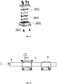
FIG. 1 is a schematic structural diagram of a sliding conductive assembly of the present disclosure; -
FIG. 2 is a sectional view of a sliding conductive assembly of the present disclosure; -
FIG. 3 is an exploded diagram of a sliding conductive assembly of the present disclosure; -
FIG. 4 is a schematic structural diagram of the present disclosure; -
FIG. 5 is an exploded diagram of a flexible conductive rail of the present disclosure; -
FIG. 6 is a schematic structural diagram of a massage cushion of the present disclosure. - The present disclosure is further described in detail below in combination with the accompanying drawings and specific embodiments.
- As shown in
FIGS. 1-6 , a specific embodiment of the present disclosure is a flexible sliding power supply assembly, including a flexibleconductive rail 1 and a slidingconductive assembly 3. The flexibleconductive rail 1 is provided with two ormore fixing slots 4, andconductive bars 2 are mounted in the fixingslots 4 in an embedded manner. - A sliding
conductive assembly 3 is mounted on the flexibleconductive rail 1; the slidingconductive assembly 3 is in slidably electric connection with theconductive bars 2; and theconductive bars 2 are correspondingly electrically connected to a power supply and acontroller 9. - The sliding
conductive assembly 3 includes aprobe control sleeve 301,conductive probes 302, and acircuit board 303; thecircuit board 303 is mounted in theprobe control sleeve 301; and thecircuit board 303 is electrically connected with a plurality ofconductive probes 302. The probe control sleeve of the present disclosure is of a tunnel type structure. The tunnel type probe control sleeve can ensure that an assembly will not be loosened and fall off from the flexible conductive rail and can also ensure that the conductive probes are always kept in a stable electric connection state during vibration. During use, under squeezing, the probe control sleeve can also move with the flexible conductive rail to keep the stable electric connection. The traditional conductive rail adopts a rigid rail, which cannot adapt to a vibration environment of a massager and a squeezed usage scenario. - The middle part of the
probe control sleeve 301 is a connectingopening 304; by the connectingopening 304, the probe control sleeve can be mounted on the flexibleconductive rail 1; and theconductive probes 302 protrude from the connectingopening 304 and are electrically connected to theconductive bars 2 on the flexibleconductive rail 1. - One side of the
probe control sleeve 301 is provided with a connectingpart 305 fixedly connected to amassage movement 5; and eachconductive bar 2 is correspondingly electrically connected to one or moreconductive probes 302. Eachconductive probe 302 is formed by combining a copper pin, a wire and a spring. Meanwhile, a plurality of conductive probes can enlarge a contact area, which can meet a requirement for high current. - One or
more magnets 6 are mounted on an operating rail of themassage movement 5 on a back shell of a cushion body in an embedded manner; a hall switch is mounted on the circuit board of themassage movement 5; and the hall switch can determine the position of the movement by sensing a magnetic field formed by themagnets 6. - The fixing
slots 4 are ""-shaped; each fixing
slot 4 includes afixed part 401 and anopening part 402; a width and thickness of thefixed part 401 are both equal to those of eachconductive bar 2; a width of theopening part 402 is less than that of theconductive bar 2; and a thickness of theopening part 402 is less than an extending height of the copper pin. - A massage cushion adopts the flexible sliding power supply assembly. The flexible conductive rail is fixedly mounted on a
cushion body 8; the other side of thecushion body 8 is further provided with arack 7; and one ormore massage movements 5 are mounted between the flexibleconductive rail 1 and therack 7. - One side of each
massage movement 5 is meshed with therack 7; the other side of themassage movement 5 is fixedly provided with the slidingassembly 3; and themassage movement 5 is electrically connected with each conductive bar through the slidingconductive assembly 3. - The fixing
slots 4 of the flexibleconductive rail 1 are inwardly disposed; thecircuit board 303 of theprobe control sleeve 301 and one side of eachconductive probe 302 is inwardly disposed; and a massage head on eachmassage movement 5 is outwardly disposed. - An upper surface and a lower surface of the
probe control sleeve 301 are both of arc curved structures. - A control method is applied to a massage cushion. The flexible conductive rail is provided with three conductive bars; two conductive bars are used for supplying power, and the third conductive bar is used for controlling signals; the conductive bars are also electrically connected with a controller; the circuit board is also electrically connected with an MCU; and the control method specifically includes the following steps:
- S1, control: issuing, by means of a mobile phone or the controller, an instruction; encoding the instruction through a communication protocol; transmitting the encoded instruction to the MCU via a specified conductive bar; and decoding, by the MCU, the encoded instruction to control the massage movement to perform a specified action; and
- S2, feedback: when the massage movement switches a mode or stops working, encoding, by the MCU, a state; transmitting the encoded state to the controller via a specified conductive bar; and decoding, by a central processing unit (CPU) on the controller, the encoded state to obtain a working state of the massage movement.
- The control method further includes step S3, positioning: sensing, by the MCU, a magnet on a back shell rail of the cushion body through the hall switch on the circuit board; after the MCU determines the position of the massage movement, encoding, by the MCU, position information; transmitting the encoded position information to the controller via a specified conductive bar; and decoding, by the CPU on the controller, the encoded position information to obtain the position information of the massage movement.
- When the movement of the traditional massage cushion walks up and down to achieve massage, a connecting wire is easy to break due to a bend. The following problems are solved: When the movement of the massage cushion walks up and down to achieve massage, since the connecting spring-shape wire has a large diameter, the diameter of the spring-shape wire is extremely large during making of an ultrathin structure, and a person will squeeze the spring-shape wire when the person leans against the massage cushion. As a result, the existing fixed conductive guide rail is pulled apart since the wire is not extensible, and the adaptability is poor. Special conductive guide rails are required to be designed for use for different massage cushions, and special molds need to be opened to manufacture the conductive guide rails. An existing guide rail conduction device is fixed in a pressed manner. The conduction device is easy to jump when moving along a conductive rail, resulting in poor intermittent contact, affecting power supplying and signal transmission, and causing part of signals to be lost. The pressed fixed guide rail has the risk of derailment. For example, in a novel conductive structure of a massage chair movement ZL201820665485.X, its conductive assembly cannot be applied to a flexible conductive rail. If the conductive assembly is forcibly combined with the flexible conductive rail, the conductive assembly is squeezed to easily cause derailment or poor contact. The existing guide rail adopts a single carbon brush (or conductive pillar) to contact a conductive metal bar on the guide rail to achieve electricity or signal transmission. When there is debris such as dust on the conductive bar, the conduction device is easy to jump, resulting in poor intermittent contact, which affects the power supplying and signal transmission and causes part of signals to be lost.
- The flexible conductive rail of the present disclosure is made of high-toughness engineering plastic. The flexible conductive rail can bend in a large arc in one direction to adapt to massage chairs with different shapes, so that the adaptability is good, and it can be used for both a common cushion and a curved cushion. In the flexible conductive rail, the tunnel type sliding conductive assembly can be made to be a standard component, thus adapting to various kinds of cushions, reducing the development cost, facilitating the assembling, reducing the kinds of materials, and decreasing the product cost. The flexible conductive rail is connected by the tunnel type probe control sleeve structure, so that reliable fixing is achieved during sliding guidance, and the problem of derailment is completely solved. Each conductive bar corresponds to two conductive probes. The parallel conductive probes have good contact-conducting stability, so that the problem of poor contact easily caused in the existing fixed conductive rail is solved. In the flexible conductive rail of the present disclosure, one controller can be connected to a plurality of massage movements with the tunnel type sliding conductive assemblies by only three conductive bars, so that the number of wires is reduced, and the problems of breakage of wires of the massage cushion and twining of the wires on a massage head are completely solved. The flexible conductive rail has a normative appearance and a compact structure, and the moving trajectory can be fixed according to the movement. The sliding conductive assembly is located on a side surface. One protruding end of the circuit board of the sliding conductive assembly is located on an inner side, and at the same time, the upper and lower end parts of the sliding conductive assembly are both arc-shaped, so that a position where a person easily squeezes can be bypassed; a product has more stable quality; and the person feels more comfortable during massage.
- The above descriptions are only the preferred embodiments of the present disclosure, and are not intended to limit the present disclosure. Any subtle modifications, equivalent replacements and improvements that are made to the above embodiments according to the technical essence of the present disclosure shall fall within the protection scope of the technical solution of the present disclosure.
Claims (9)
- A flexible sliding power supply assembly, comprising a flexible conductive rail and a sliding conductive assembly, wherein the flexible conductive rail is provided with two or more fixing slots; conductive bars are mounted in the fixing slots in an embedded manner;
the sliding conductive assembly is mounted on the flexible conductive rail; the sliding conductive assembly is in slidably electric connection with the conductive bars; and the conductive bars are correspondingly electrically connected to a power supply and a controller. - The flexible sliding power supply assembly according to claim 1, wherein the sliding conductive assembly comprises a probe control sleeve, conductive probes, and a circuit board; the circuit board is mounted in the probe control sleeve; the circuit board is electrically connected with a plurality of conductive probes;
the middle part of the probe control sleeve is a connecting opening; by the connecting opening, the probe control sleeve is capable of being mounted on the flexible conductive rail; and the conductive probes protrude from the connecting opening and are electrically connected to the conductive bars on the flexible conductive rail. - The flexible sliding power supply assembly according to claim 2, wherein one side of the probe control sleeve is provided with a connecting part fixedly connected to a massage movement; and each conductive bar is correspondingly electrically connected to one or more conductive probes.
- The flexible sliding power supply assembly according to claim 2, wherein one or more magnets are mounted on the flexible conductive rail in an embedded manner; a hall switch is mounted on the circuit board; and the hall switch is capable of determining the position of the movement by sensing a magnetic field formed by the magnets.
- The flexible sliding power supply assembly according to claim 3, wherein the fixing slots are ""-shaped; each fixing slot comprises a fixed part and an opening part; a width and thickness of the fixed part are both equal to those of each conductive bar; a width of the opening part is less than that of the conductive bar; and a thickness of the opening part is less than an extending height of the conductive probe.

- A massage cushion, which adopts the flexible sliding power supply assembly according to any one of claims 1 to 5, wherein the flexible conductive rail is fixedly mounted on a cushion body; the other side of the cushion body is further provided with a rack; one or more massage movements are mounted between the flexible conductive rail and the rack;
one side of each massage movement is meshed with the rack; the other side of the massage movement is fixedly provided with the sliding conductive assembly; and the massage movement is electrically connected with each conductive bar through the sliding conductive assembly. - The massage cushion according to claim 1, wherein the fixing slots of the flexible conductive rail are inwardly disposed; the circuit board of the probe control sleeve and one side of each conductive probe is also inwardly disposed; a massage head on each massage movement is outwardly disposed; and
an upper surface and a lower surface of the probe control sleeve are both of arc curved structures. - A control method, which is applied to the massage cushion according to any one of claims 1 to 3, wherein the flexible conductive rail is provided with three conductive bars; two conductive bars are used for supplying power, and the third conductive bar is used for controlling signals; the conductive bars are also electrically connected with a controller; the circuit board is also electrically connected with a micro control unit (MCU); and the control method specifically comprises the following steps:S1, control: issuing, by means of a mobile phone or the controller, an instruction; encoding the instruction through a communication protocol; transmitting the encoded instruction to the MCU via a specified conductive bar; and decoding, by the MCU, the encoded instruction to control the massage movement to perform a specified action; andS2, feedback: when the massage movement switches a mode or stops working, encoding, by the MCU, a state; transmitting the encoded state to the controller via a specified conductive bar; and decoding, by a central processing unit (CPU) on the controller, the encoded state to obtain a working state of the massage movement.
- The control method according to claim 8, further comprising step S3, positioning: sensing, by the MCU, a magnet on a back shell rail of the cushion body through the hall switch on the circuit board; after the MCU determines the position of the massage movement, encoding, by the MCU, position information; transmitting the encoded position information to the controller via a specified conductive bar; and decoding, by the CPU on the controller, the encoded position information to obtain the position information of the massage movement.
Applications Claiming Priority (2)
| Application Number | Priority Date | Filing Date | Title |
|---|---|---|---|
| CN202011496068.5A CN112510458B (en) | 2020-12-17 | 2020-12-17 | Flexible sliding power supply assembly, massage back cushion and control method of massage back cushion |
| PCT/CN2021/000073 WO2022126798A1 (en) | 2020-12-17 | 2021-04-08 | Flexible sliding power supply assembly, massage cushion, and control method therefor |
Publications (4)
| Publication Number | Publication Date |
|---|---|
| EP4064466A1 true EP4064466A1 (en) | 2022-09-28 |
| EP4064466A4 EP4064466A4 (en) | 2023-12-20 |
| EP4064466C0 EP4064466C0 (en) | 2026-02-18 |
| EP4064466B1 EP4064466B1 (en) | 2026-02-18 |
Family
ID=74922165
Family Applications (1)
| Application Number | Title | Priority Date | Filing Date |
|---|---|---|---|
| EP21904616.6A Active EP4064466B1 (en) | 2020-12-17 | 2021-04-08 | Flexible sliding power supply assembly, massage cushion, and control method therefor |
Country Status (6)
| Country | Link |
|---|---|
| US (1) | US20240164981A1 (en) |
| EP (1) | EP4064466B1 (en) |
| JP (1) | JP3240442U (en) |
| KR (1) | KR102755140B1 (en) |
| CN (1) | CN112510458B (en) |
| WO (1) | WO2022126798A1 (en) |
Families Citing this family (3)
| Publication number | Priority date | Publication date | Assignee | Title |
|---|---|---|---|---|
| CN112510458B (en) * | 2020-12-17 | 2023-03-31 | 深圳市盟迪奥科技股份有限公司 | Flexible sliding power supply assembly, massage back cushion and control method of massage back cushion |
| CN113456447A (en) * | 2021-07-05 | 2021-10-01 | 深圳市盟迪奥科技股份有限公司 | Self-adaptive flexible massage structural part |
| CN222777468U (en) * | 2024-09-29 | 2025-04-22 | 厦门爱玛康科技有限公司 | Sliding rail type massage mechanism, massage cushion and sofa |
Family Cites Families (29)
| Publication number | Priority date | Publication date | Assignee | Title |
|---|---|---|---|---|
| FR2671673B1 (en) * | 1991-01-10 | 1996-01-19 | Sole Eric | ELECTRICITY DISTRIBUTION LINE AND ADAPTER FOR SUCH A LINE. |
| US5561271A (en) * | 1994-03-23 | 1996-10-01 | Bruck Gmbh & Co. Kg | Low-voltage power cable |
| DE9417134U1 (en) * | 1994-10-25 | 1994-12-15 | Siemens AG, 80333 München | Data transmission system |
| US6283928B1 (en) * | 2000-03-10 | 2001-09-04 | Kuo-An Wang | Massage apparatus |
| CN2609236Y (en) * | 2003-01-22 | 2004-03-31 | 李海军 | Hanging type transmission guide rail |
| US6808500B1 (en) * | 2003-03-28 | 2004-10-26 | Yu Cheng-Yi | Roller massager having rocking or kneading massaging motions |
| US7128721B2 (en) * | 2004-04-30 | 2006-10-31 | Homedics, Inc. | Portable body massager |
| US7419475B2 (en) * | 2005-09-09 | 2008-09-02 | Fka Distibuting Co. | Body massager with illumination effects |
| SE534019C2 (en) * | 2009-08-04 | 2011-04-05 | Xcen Ab | Power supply device |
| CN202568798U (en) * | 2012-04-18 | 2012-12-05 | 厦门兴翔天电子有限公司 | Conducting structure for massager |
| CN102935032B (en) * | 2012-11-23 | 2014-07-09 | 李耀辉 | Folding message bed |
| JP6470882B2 (en) * | 2013-04-18 | 2019-02-13 | ファミリーイナダ株式会社 | Massage machine |
| AT514981B1 (en) * | 2013-10-11 | 2016-01-15 | Tgw Mechanics Gmbh | Conveyor roller and conveyor with moisture protection |
| DE102015001154A1 (en) * | 2015-02-02 | 2016-08-04 | Oliver Betz | assembly arrangement |
| DE102016204103A1 (en) * | 2016-03-11 | 2017-09-14 | Geze Gmbh | FLEXIBLE CABLE TRANSITION |
| AT518471B1 (en) * | 2016-04-13 | 2018-04-15 | Tgw Mechanics Gmbh | Conveying system for conveying piece goods with improved electrical connection system as well as modular system of connection boxes |
| DE102017102130B4 (en) * | 2017-02-03 | 2019-03-14 | Lisa Dräxlmaier GmbH | Housing element, electrical line assembly and manufacturing method thereof |
| EP3382273B1 (en) * | 2017-03-29 | 2024-04-17 | Inventronics GmbH | Lighting module and lighting system |
| US10283952B2 (en) * | 2017-06-22 | 2019-05-07 | Bretford Manufacturing, Inc. | Rapidly deployable floor power system |
| JP6901914B2 (en) * | 2017-06-26 | 2021-07-14 | 日本発條株式会社 | Power supply and vehicle seats |
| US11358497B2 (en) * | 2018-05-04 | 2022-06-14 | Lear Corporation | Track system having a rolling member |
| CN209611675U (en) * | 2018-05-07 | 2019-11-12 | 上海荣泰健康科技股份有限公司 | A kind of novel conductive structure of massage chair movement |
| CN209827440U (en) * | 2019-01-28 | 2019-12-24 | 上海派笙电子科技有限公司 | Shoulder position detection device of massage chair |
| CN110707446A (en) * | 2019-10-08 | 2020-01-17 | 赛尔富电子有限公司 | A waterproof track type power taking system and power supply rack |
| CN110664598A (en) * | 2019-10-26 | 2020-01-10 | 温岭市智方科技有限公司 | Adjustable multifunctional massager |
| US11332086B2 (en) * | 2019-11-22 | 2022-05-17 | Ford Global Technologies, Llc | Track assembly with electrical connection system |
| CN110836337A (en) * | 2019-11-27 | 2020-02-25 | 广州雄义精密五金有限公司 | Series-connection type LED light source module and combined lamp thereof |
| TWI758805B (en) * | 2020-07-31 | 2022-03-21 | 瑪莎生活科技有限公司 | Back massaging device and its controlling method of massage route |
| CN112510458B (en) * | 2020-12-17 | 2023-03-31 | 深圳市盟迪奥科技股份有限公司 | Flexible sliding power supply assembly, massage back cushion and control method of massage back cushion |
-
2020
- 2020-12-17 CN CN202011496068.5A patent/CN112510458B/en active Active
-
2021
- 2021-04-08 JP JP2022600103U patent/JP3240442U/en active Active
- 2021-04-08 US US17/787,949 patent/US20240164981A1/en active Pending
- 2021-04-08 WO PCT/CN2021/000073 patent/WO2022126798A1/en not_active Ceased
- 2021-04-08 KR KR1020227025516A patent/KR102755140B1/en active Active
- 2021-04-08 EP EP21904616.6A patent/EP4064466B1/en active Active
Also Published As
| Publication number | Publication date |
|---|---|
| CN112510458B (en) | 2023-03-31 |
| US20240164981A1 (en) | 2024-05-23 |
| EP4064466A4 (en) | 2023-12-20 |
| WO2022126798A1 (en) | 2022-06-23 |
| KR20220127264A (en) | 2022-09-19 |
| JP3240442U (en) | 2023-01-11 |
| EP4064466C0 (en) | 2026-02-18 |
| KR102755140B1 (en) | 2025-01-21 |
| EP4064466B1 (en) | 2026-02-18 |
| CN112510458A (en) | 2021-03-16 |
Similar Documents
| Publication | Publication Date | Title |
|---|---|---|
| EP4064466B1 (en) | Flexible sliding power supply assembly, massage cushion, and control method therefor | |
| CN109288661A (en) | A kind of neurosurgical care massage machine | |
| CN222195455U (en) | Novel massage pad structure | |
| CN109481257A (en) | The mobile massage mechanism of three axis and muscles along the regular meridians conditioning device | |
| CN213641961U (en) | Limb nerve recovery nursing device | |
| TWM634868U (en) | Flexible sliding power supply component and massage cushion | |
| CN219681058U (en) | Adjustable head hoop | |
| CN217186938U (en) | Massage components and neck massager | |
| CN212038192U (en) | Massage head and massager | |
| CN222641093U (en) | Transmission gearbox capable of realizing EMS conduction | |
| CN224207057U (en) | Massage core and massage equipment | |
| CN211095916U (en) | Fascia gun | |
| CN210728184U (en) | Intelligent massager assembly capable of being controlled by mobile phone | |
| CN222929993U (en) | Dual-purpose massage backrest | |
| CN212118571U (en) | Self-adaptive massage pillow | |
| CN217853748U (en) | Shared massage chair with adjustable head support | |
| CN209172836U (en) | A kind of massage armchair frame structure | |
| CN220293813U (en) | Head massager with detection module | |
| CN219090091U (en) | Massage head mechanism and massage device | |
| CN222968212U (en) | Modular assembled intelligent bed | |
| CN219921514U (en) | Waist massage instrument | |
| CN220898351U (en) | Supporting force adjusting mechanism for sponge mattress | |
| CN222566627U (en) | Massage head and massage device | |
| CN216933960U (en) | A massage mechanism in an intelligent massage device with a simplified structure | |
| CN218739879U (en) | Neck massager convenient to adjust massage piece interval |
Legal Events
| Date | Code | Title | Description |
|---|---|---|---|
| STAA | Information on the status of an ep patent application or granted ep patent |
Free format text: STATUS: UNKNOWN |
|
| STAA | Information on the status of an ep patent application or granted ep patent |
Free format text: STATUS: THE INTERNATIONAL PUBLICATION HAS BEEN MADE |
|
| PUAI | Public reference made under article 153(3) epc to a published international application that has entered the european phase |
Free format text: ORIGINAL CODE: 0009012 |
|
| STAA | Information on the status of an ep patent application or granted ep patent |
Free format text: STATUS: REQUEST FOR EXAMINATION WAS MADE |
|
| 17P | Request for examination filed |
Effective date: 20220621 |
|
| AK | Designated contracting states |
Kind code of ref document: A1 Designated state(s): AL AT BE BG CH CY CZ DE DK EE ES FI FR GB GR HR HU IE IS IT LI LT LU LV MC MK MT NL NO PL PT RO RS SE SI SK SM TR |
|
| REG | Reference to a national code |
Ref country code: DE Ipc: A61H0001000000 Ref legal event code: R079 Ref document number: 602021048445 Country of ref document: DE Free format text: PREVIOUS MAIN CLASS: H01R0041000000 |
|
| A4 | Supplementary search report drawn up and despatched |
Effective date: 20231120 |
|
| RIC1 | Information provided on ipc code assigned before grant |
Ipc: A61H 7/00 20060101ALN20231114BHEP Ipc: G16H 20/30 20180101ALN20231114BHEP Ipc: H01R 25/14 20060101ALN20231114BHEP Ipc: A61H 1/00 20060101AFI20231114BHEP |
|
| DAV | Request for validation of the european patent (deleted) | ||
| DAX | Request for extension of the european patent (deleted) | ||
| RIC1 | Information provided on ipc code assigned before grant |
Ipc: A61H 1/00 20060101AFI20250725BHEP Ipc: H01R 25/14 20060101ALN20250725BHEP Ipc: G16H 20/30 20180101ALN20250725BHEP Ipc: A61H 7/00 20060101ALN20250725BHEP |
|
| GRAP | Despatch of communication of intention to grant a patent |
Free format text: ORIGINAL CODE: EPIDOSNIGR1 |
|
| STAA | Information on the status of an ep patent application or granted ep patent |
Free format text: STATUS: GRANT OF PATENT IS INTENDED |
|
| RIC1 | Information provided on ipc code assigned before grant |
Ipc: A61H 1/00 20060101AFI20250828BHEP Ipc: H01R 25/14 20060101ALN20250828BHEP Ipc: G16H 20/30 20180101ALN20250828BHEP Ipc: A61H 7/00 20060101ALN20250828BHEP |
|
| INTG | Intention to grant announced |
Effective date: 20250908 |
|
| GRAS | Grant fee paid |
Free format text: ORIGINAL CODE: EPIDOSNIGR3 |
|
| GRAA | (expected) grant |
Free format text: ORIGINAL CODE: 0009210 |
|
| STAA | Information on the status of an ep patent application or granted ep patent |
Free format text: STATUS: THE PATENT HAS BEEN GRANTED |
|
| AK | Designated contracting states |
Kind code of ref document: B1 Designated state(s): AL AT BE BG CH CY CZ DE DK EE ES FI FR GB GR HR HU IE IS IT LI LT LU LV MC MK MT NL NO PL PT RO RS SE SI SK SM TR |
|
| REG | Reference to a national code |
Ref country code: CH Ref legal event code: F10 Free format text: ST27 STATUS EVENT CODE: U-0-0-F10-F00 (AS PROVIDED BY THE NATIONAL OFFICE) Effective date: 20260218 Ref country code: GB Ref legal event code: FG4D |
|
| REG | Reference to a national code |
Ref country code: DE Ref legal event code: R096 Ref document number: 602021048445 Country of ref document: DE |
|
| REG | Reference to a national code |
Ref country code: IE Ref legal event code: FG4D |
|
| U01 | Request for unitary effect filed |
Effective date: 20260316 |
|
| U07 | Unitary effect registered |
Designated state(s): AT BE BG DE DK EE FI FR IT LT LU LV MT NL PT RO SE SI Effective date: 20260320 |
|
| U20 | Renewal fee for the european patent with unitary effect paid |
Year of fee payment: 6 Effective date: 20260325 |