EP4064458B1 - Terminal-equipped electric wire - Google Patents
Terminal-equipped electric wire Download PDFInfo
- Publication number
- EP4064458B1 EP4064458B1 EP22162180.8A EP22162180A EP4064458B1 EP 4064458 B1 EP4064458 B1 EP 4064458B1 EP 22162180 A EP22162180 A EP 22162180A EP 4064458 B1 EP4064458 B1 EP 4064458B1
- Authority
- EP
- European Patent Office
- Prior art keywords
- core wire
- terminal
- electric wire
- pair
- exposed part
- Prior art date
- Legal status (The legal status is an assumption and is not a legal conclusion. Google has not performed a legal analysis and makes no representation as to the accuracy of the status listed.)
- Active
Links
Images


Classifications
-
- H—ELECTRICITY
- H01—ELECTRIC ELEMENTS
- H01R—ELECTRICALLY-CONDUCTIVE CONNECTIONS; STRUCTURAL ASSOCIATIONS OF A PLURALITY OF MUTUALLY-INSULATED ELECTRICAL CONNECTING ELEMENTS; COUPLING DEVICES; CURRENT COLLECTORS
- H01R13/00—Details of coupling devices of the kinds covered by groups H01R12/70 or H01R24/00 - H01R33/00
- H01R13/46—Bases; Cases
- H01R13/52—Dustproof, splashproof, drip-proof, waterproof, or flameproof cases
-
- H—ELECTRICITY
- H01—ELECTRIC ELEMENTS
- H01R—ELECTRICALLY-CONDUCTIVE CONNECTIONS; STRUCTURAL ASSOCIATIONS OF A PLURALITY OF MUTUALLY-INSULATED ELECTRICAL CONNECTING ELEMENTS; COUPLING DEVICES; CURRENT COLLECTORS
- H01R4/00—Electrically-conductive connections between two or more conductive members in direct contact, i.e. touching one another; Means for effecting or maintaining such contact; Electrically-conductive connections having two or more spaced connecting locations for conductors and using contact members penetrating insulation
- H01R4/58—Electrically-conductive connections between two or more conductive members in direct contact, i.e. touching one another; Means for effecting or maintaining such contact; Electrically-conductive connections having two or more spaced connecting locations for conductors and using contact members penetrating insulation characterised by the form or material of the contacting members
- H01R4/62—Connections between conductors of different materials; Connections between or with aluminium or steel-core aluminium conductors
-
- H—ELECTRICITY
- H01—ELECTRIC ELEMENTS
- H01R—ELECTRICALLY-CONDUCTIVE CONNECTIONS; STRUCTURAL ASSOCIATIONS OF A PLURALITY OF MUTUALLY-INSULATED ELECTRICAL CONNECTING ELEMENTS; COUPLING DEVICES; CURRENT COLLECTORS
- H01R13/00—Details of coupling devices of the kinds covered by groups H01R12/70 or H01R24/00 - H01R33/00
- H01R13/02—Contact members
-
- H—ELECTRICITY
- H01—ELECTRIC ELEMENTS
- H01R—ELECTRICALLY-CONDUCTIVE CONNECTIONS; STRUCTURAL ASSOCIATIONS OF A PLURALITY OF MUTUALLY-INSULATED ELECTRICAL CONNECTING ELEMENTS; COUPLING DEVICES; CURRENT COLLECTORS
- H01R13/00—Details of coupling devices of the kinds covered by groups H01R12/70 or H01R24/00 - H01R33/00
- H01R13/46—Bases; Cases
- H01R13/52—Dustproof, splashproof, drip-proof, waterproof, or flameproof cases
- H01R13/5216—Dustproof, splashproof, drip-proof, waterproof, or flameproof cases characterised by the sealing material, e.g. gels or resins
-
- H—ELECTRICITY
- H01—ELECTRIC ELEMENTS
- H01R—ELECTRICALLY-CONDUCTIVE CONNECTIONS; STRUCTURAL ASSOCIATIONS OF A PLURALITY OF MUTUALLY-INSULATED ELECTRICAL CONNECTING ELEMENTS; COUPLING DEVICES; CURRENT COLLECTORS
- H01R4/00—Electrically-conductive connections between two or more conductive members in direct contact, i.e. touching one another; Means for effecting or maintaining such contact; Electrically-conductive connections having two or more spaced connecting locations for conductors and using contact members penetrating insulation
- H01R4/10—Electrically-conductive connections between two or more conductive members in direct contact, i.e. touching one another; Means for effecting or maintaining such contact; Electrically-conductive connections having two or more spaced connecting locations for conductors and using contact members penetrating insulation effected solely by twisting, wrapping, bending, crimping, or other permanent deformation
- H01R4/18—Electrically-conductive connections between two or more conductive members in direct contact, i.e. touching one another; Means for effecting or maintaining such contact; Electrically-conductive connections having two or more spaced connecting locations for conductors and using contact members penetrating insulation effected solely by twisting, wrapping, bending, crimping, or other permanent deformation by crimping
- H01R4/183—Electrically-conductive connections between two or more conductive members in direct contact, i.e. touching one another; Means for effecting or maintaining such contact; Electrically-conductive connections having two or more spaced connecting locations for conductors and using contact members penetrating insulation effected solely by twisting, wrapping, bending, crimping, or other permanent deformation by crimping for cylindrical elongated bodies, e.g. cables having circular cross-section
- H01R4/184—Electrically-conductive connections between two or more conductive members in direct contact, i.e. touching one another; Means for effecting or maintaining such contact; Electrically-conductive connections having two or more spaced connecting locations for conductors and using contact members penetrating insulation effected solely by twisting, wrapping, bending, crimping, or other permanent deformation by crimping for cylindrical elongated bodies, e.g. cables having circular cross-section comprising a U-shaped wire-receiving portion
- H01R4/185—Electrically-conductive connections between two or more conductive members in direct contact, i.e. touching one another; Means for effecting or maintaining such contact; Electrically-conductive connections having two or more spaced connecting locations for conductors and using contact members penetrating insulation effected solely by twisting, wrapping, bending, crimping, or other permanent deformation by crimping for cylindrical elongated bodies, e.g. cables having circular cross-section comprising a U-shaped wire-receiving portion combined with a U-shaped insulation-receiving portion
-
- H—ELECTRICITY
- H01—ELECTRIC ELEMENTS
- H01R—ELECTRICALLY-CONDUCTIVE CONNECTIONS; STRUCTURAL ASSOCIATIONS OF A PLURALITY OF MUTUALLY-INSULATED ELECTRICAL CONNECTING ELEMENTS; COUPLING DEVICES; CURRENT COLLECTORS
- H01R4/00—Electrically-conductive connections between two or more conductive members in direct contact, i.e. touching one another; Means for effecting or maintaining such contact; Electrically-conductive connections having two or more spaced connecting locations for conductors and using contact members penetrating insulation
- H01R4/70—Insulation of connections
Definitions
- the present invention relates to a terminal-equipped electric wire.
- an end of the electric wire and a caulked and crimped part of a terminal fitting that is caulked and crimped to the end of the electric wire are with countermeasures against corrosion.
- Japanese Patent Application Laid-open No. JP 2018-006205 A discloses a technique of covering an exposed part of an end of an electric wire in a caulked and crimped part with a water-stopping member formed of curable resin from the outside together with the caulked and crimped part, so that the entry of liquid into a connection part between the end of the electric wire and the caulked and crimped part is suppressed.
- JP 2017-204444 A discloses a technique of making a front end of a core wire exposed part at an end of an electric wire protrude from a caulked and crimped part and providing a narrow groove at a bottom wall of a terminal fitting on which the front end of the core wire exposed part is placed, so that liquid such as water is discharged along this narrow groove.
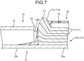
- the crimping force applied from the caulked and crimped part causes the front end protruding from the caulked and crimped part to jump up in a direction opposite to the direction of the crimping force, for example.
- the curable resin in a liquid form is applied while the front end of the core wire exposed part jumps up; therefore, the water-stopping member becomes thinner in this jumping part of the core wire exposed part than in the periphery or the formation of the water-stopping member may fail in the jumping part. Accordingly, in the terminal-equipped electric wire, the durability of the water-stopping member in the jumping part of the core wire exposed part may deteriorate.
- a terminal-equipped electric wire includes the features of claim 1. Preferred embodiments of the invention are mentioned in the dependent claims.
- terminal-equipped electric wire is described with reference to FIG. 1 to FIG. 7 .
- the terminal-equipped electric wire according to the present embodiment is denoted by 1.
- This terminal-equipped electric wire 1 includes an electric wire 10 and a terminal fitting 20 that are connected physically and electrically to each other.
- the terminal fitting 20 is attached to an end 10a of the electric wire 10 (hereinafter referred to as "electric wire end").
- the terminal-equipped electric wire 1 includes a water-stopping member 30 in order to increase the anticorrosion performance of a connection part between the electric wire end 10a and the terminal fitting 20 ( FIG. 1 and FIG. 2 ).
- the terminal fitting 20 is connected to at least one of two electric wire ends 10a of the electric wire 10.
- the terminal fitting 20 may be connected to one electric wire 10, or a plurality of the electric wires 10 may be connected by at least one terminal fitting 20 and through this terminal fitting 20, the electric wires 10 may be electrically connected to each other.
- the terminal fitting 20 is engaged with and connected to a counterpart terminal connection body of a counterpart terminal fitting so as to be physically and electrically connected to the counterpart terminal connection body, or is fixed with a screw to the counterpart terminal connection body so as to be physically and electrically connected to the counterpart terminal connection body.
- the terminal fitting 20 may physically and electrically connect the electric wires 10 so as to electrically connect all the electric wires 10 through the terminal fitting 20 itself, or at least two of the electric wires 10 may be combined as one set and the terminal fitting 20 may be provided for each set as a joint terminal to physically and electrically connect each set.
- one terminal fitting 20 that is engaged with and connected to the counterpart terminal connection body (not illustrated) is connected to the electric wire end 10a of one electric wire 10.
- the electric wire 10 includes a core wire 11 and a cover 12 that covers the core wire 11. At the electric wire end 10a, the cover 12 is removed to expose the core wire 11 ( FIG. 1 to FIG. 5 ).
- the core wire 11 is formed by a bundle of a plurality of element wires 13 made of a conductive metal wire material.
- the element wire 13 is molded of, for example, aluminum, aluminum alloy, copper, or copper alloy.
- the cover 12 is molded of an insulating resin material covering the core wire 11 while exposing a core wire exposed part 11a of the core wire 11 at the electric wire end 10a.
- the terminal fitting 20 is molded of a conductive material such as metal (for example, aluminum, aluminum alloy, copper, or copper alloy). This terminal fitting 20 is molded into a predetermined shape by press-molding such as a bending process or a cutting process on a metal plate that is a base material.
- a conductive material such as metal (for example, aluminum, aluminum alloy, copper, or copper alloy).
- This terminal fitting 20 includes a terminal connection body 21 to be electrically connected to the counterpart terminal connection body of the counterpart terminal fitting ( FIG. 1 to FIG. 6 ).
- one of the terminal connection body 21 and the counterpart terminal connection body is formed to have a female terminal shape and the other is formed to have a male terminal shape.
- the terminal connection body 21 and the counterpart terminal connection body are physically and electrically connected to each other as they are engaged with each other by insertion.
- the terminal connection body 21 is formed as a female terminal with a square tubular box shape
- the counterpart terminal connection body is formed as a male terminal with a male tab shape.
- This terminal fitting 20 includes a bottom wall 22 on which the electric wire end 10a is placed in the state as the terminal-equipped electric wire 1 ( FIG. 1 to FIG. 6 ).
- This terminal fitting 20 includes a pair of core wire caulking pieces 23 and 23 ( FIG. 1 to FIG. 6 ) that rises from the bottom wall 22 and caulks and crimps the core wire exposed part 11a together with the bottom wall 22 while a front end 11b of the core wire exposed part 11a protrudes, and a pair of cover caulking pieces 24 and 24 ( FIG. 1 , FIG. 3 , FIG. 4 , and FIG.
- the terminal fitting 20 additionally includes a pair of side walls (hereinafter referred to as "first side walls") 25 and 25 ( FIG. 1 to FIG. 6 ) that rises from the bottom wall 22 for the respective core wire caulking pieces 23 and 23, is coupled to the bottom wall 22 side of the core wire caulking pieces 23 and 23, and exposes the front end 11b of the core wire exposed part 11a from an opening 25a between the respective end parts.
- first side walls a pair of side walls
- This terminal fitting 20 moreover includes a pair of side walls (hereinafter referred to as "second side walls") 26 and 26 ( FIG. 1 , FIG. 3 , FIG. 4 , and FIG. 6 ) that rises from the bottom wall 22 for the respective core wire caulking pieces 23 and 23, couples the bottom wall 22 side of the core wire caulking pieces 23 and 23 to the bottom wall 22 side of the cover caulking pieces 24 and 24, and exposes the electric wire end 10a from an opening 26a between the respective end parts between the pair of core wire caulking pieces 23 and 23 and the pair of cover caulking pieces 24 and 24.
- second side walls a pair of side walls (hereinafter referred to as "second side walls") 26 and 26 ( FIG. 1 , FIG. 3 , FIG. 4 , and FIG. 6 ) that rises from the bottom wall 22 for the respective core wire caulking pieces 23 and 23, couples the bottom wall 22 side of the core wire caulking pieces 23 and 23 to the bottom wall 22 side of the cover caulking pieces 24 and 24, and exposes
- the bottom wall 22 includes a first bottom part 22a from which the pair of core wire caulking pieces 23 and 23, the pair of cover caulking pieces 24 and 24, the pair of first side walls 25 and 25, and the pair of second side walls 26 and 26 rise, and a second bottom part 22b constituting a part of a wall part of the terminal connection body 21 and continuing to the first bottom part 22a ( FIG. 1 to FIG. 6 ). That is to say, the bottom wall 22 includes the first bottom part 22a on which the electric wire end 10a is placed, and the second bottom part 22b constituting a part of the wall part of the terminal connection body 21.
- both the first bottom part 22a and the second bottom part 22b are formed to have a flat plate shape or an arc shape, or one of the first bottom part 22a and the second bottom part 22b is formed to have a flat plate shape and the other is formed to have an arc shape.
- both the first bottom part 22a and the second bottom part 22b are formed to have a flat plate shape.
- Each of the pair of core wire caulking pieces 23 and 23 is a piece body protruding from both ends in a direction orthogonal to the axial direction of the electric wire end 10a at the first bottom part 22a on which the electric wire end 10a is placed ( FIG. 1 , FIG. 3 , FIG. 4 , and FIG. 6 ).
- the pair of core wire caulking pieces 23 and 23 protrudes in a direction intersecting with the wall surface of the first bottom part 22a and is disposed to face each other with a space therebetween, so that the first bottom part 22a and the pair of core wire caulking pieces 23 and 23 form a U-shape ( FIG. 3 ).
- the core wire exposed part 11a of the electric wire end 10a is placed on the first bottom part 22a serving as a bottom of the U-shape and pressure is applied to the core wire exposed part 11a while the pair of core wire caulking pieces 23 and 23 is wound around the core wire exposed part 11a, and thus, the core wire exposed part 11a is caulked and crimped. Therefore, the core wire exposed part 11a is physically and electrically connected to the first bottom part 22a and the pair of core wire caulking pieces 23 and 23.
- the front end 11b of the core wire exposed part 11a protrudes toward the pair of first side walls 25 and 25 and a rear end of the core wire exposed part 11a (end part on the cover 12 side) protrudes toward the pair of second side walls 26 and 26 ( FIG. 1 and FIG. 4 ).
- a serration region 27 including at least one of a plurality of concave parts and a plurality of convex parts is formed on an inner wall surface ranging from one core wire caulking piece 23 to the other core wire caulking piece 23 ( FIG. 3 and FIG. 6 ).
- the contact area with the core wire exposed part 11a is increased in the serration region 27, so that the adhesion strength therebetween is increased to improve the contact reliability, and thus, the electric connection state therebetween is improved.
- This serration region 27 is formed at a place avoiding a concave part 22c of the first bottom part 22a, which is described below.
- Each of the pair of cover caulking pieces 24 and 24 is a piece body that, at the first bottom part 22a where the electric wire end 10a is placed, protrudes from both ends in the direction orthogonal to the axial direction of the electric wire end 10a ( FIG. 1 , FIG. 3 , FIG. 4 , and FIG. 6 ).
- the pair of cover caulking pieces 24 and 24 protrudes in the direction intersecting with the wall surface of the first bottom part 22a and is disposed to face each other with a space therebetween; thus, the first bottom part 22a and the pair of cover caulking pieces 24 and 24 form a U-shape ( FIG. 3 ).
- the cover end part 12a of the electric wire end 10a is placed on the first bottom part 22a, which constitutes the bottom of the U-shape, and pressure is applied to the cover end part 12a while the pair of cover caulking pieces 24 and 24 is wound around this cover end part 12a and thus, the cover end part 12a is caulked and crimped.
- cover end part 12a While the cover end part 12a is caulked and crimped by the pair of cover caulking pieces 24 and 24, a front end of the cover end part 12a (end part on the core wire exposed part 11a side) protrudes toward the pair of second side walls 26 and 26 ( FIG. 1 and FIG. 4 ). In this terminal fitting 20, the electric wire 10 is extracted out of the pair of cover caulking pieces 24 and 24.
- Each of the pair of first side walls 25 and 25 is a piece body that, at the first bottom part 22a where the electric wire end 10a is placed, protrudes from both ends in the direction orthogonal to the axial direction of the electric wire end 10a ( FIG. 1 , FIG. 3 , FIG. 4 , and FIG. 6 ).
- the pair of first side walls 25 and 25 protrudes in the direction intersecting with the wall surface of the first bottom part 22a and is disposed to face each other with a space therebetween.
- One of the pair of first side walls 25 and 25 is coupled to the first bottom part 22a side of one core wire caulking piece 23, and the other first side wall 25 is coupled to the first bottom part 22a side of the other core wire caulking piece 23.
- the terminal connection body 21 is coupled to the pair of first side walls 25 and 25 on the side opposite to the pair of core wire caulking pieces 23 and 23.
- the opening 25a for exposing the front end 11b of the core wire exposed part 11a is formed ( FIG. 1, FIG. 2 , FIG. 4 , and FIG. 5 ).
- Each of the pair of second side walls 26 and 26 is a piece body that, at the first bottom part 22a where the electric wire end 10a is placed, protrudes from both ends in the direction orthogonal to the axial direction of the electric wire end 10a ( FIG. 1 , FIG. 3 , FIG. 4 , and FIG. 6 ).
- the pair of second side walls 26 and 26 protrudes in the direction intersecting with the wall surface of the first bottom part 22a and is disposed to face each other with a space therebetween.
- One of the pair of second side walls 26 and 26 is coupled to the first bottom part 22a side of one core wire caulking piece 23 and to the first bottom part 22a side of one cover caulking piece 24, and the other second side wall 26 is coupled to the first bottom part 22a side of the other core wire caulking piece 23 and to the first bottom part 22a side of the other cover caulking piece 24.
- the opening 26a for exposing the electric wire end 10a is formed ( FIG. 1 and FIG. 4 ).
- the opening 26a described here exposes the rear end of the core wire exposed part 11a (end part on the cover 12 side) at the electric wire end 10a and the front end of the cover end part 12a (end part on the core wire exposed part 11a side).
- the bottom wall 22 of the terminal fitting 20 includes the concave part 22c that continues from a place facing end parts 23a of the pair of core wire caulking pieces 23 and 23 on the first side walls 25 and 25 side (that is, on the front end 11b side of the core wire exposed part 11a) to a front end surface 11b 1 of the front end 11b of the core wire exposed part 11a.
- the concave part 22c receives the bottom wall 22 in the range of the place where the core wire exposed part 11a is caulked and crimped by the end parts 23a of the pair of core wire caulking pieces 23 and 23 to the front end surface 11b 1 ( FIG. 2 , FIG. 5, and FIG. 6 ).
- This concave part 22c is formed in the first bottom part 22a.
- the concave part 22c described here is depressed in a rectangular shape from one first side wall 25 to the other first side wall 25 in the concave part formation target range from the place facing the end parts 23a of the pair of core wire caulking pieces 23 and 23 on an inner wall surface of the first bottom part 22a to the tip of the front end surface 11b 1 of the core wire exposed part 11a ( FIG. 6 ).
- the core wire exposed part 11a enters the concave part 22c with the crimping force from this pair of core wire caulking pieces 23 and 23.
- the concave part 22c is formed with the size that can form the space from the front end surface 11b 1 in the state where the core wire exposed part 11a is inside in order to make the concavity continue to the tip of the front end surface 11b 1 of the core wire exposed part 11a ( FIG. 2 and FIG. 5 ).
- the crimping force from the pair of core wire caulking pieces 23 and 23 and the first bottom part 22a of the bottom wall 22 after the caulking and crimping acts on the core wire exposed part 11a and therefore, the force in the direction opposite to the direction of the crimping force from the pair of core wire caulking pieces 23 and 23 acts on the front end 11b of the core wire exposed part 11a supported on the first bottom part 22a side. Accordingly, the front end 11b of the core wire exposed part 11a jumps up in the direction of the opposite force.
- the core wire exposed part 11a enters the concave part 22c on the first bottom part 22a side and thus, the jumping of a jumping part 11c of the front end 11b of the core wire exposed part 11a can be suppressed to be a small quantity ( FIG. 2 and FIG. 5 ).
- the water-stopping member 30 covers the exposed part of the electric wire end 10a in the terminal fitting 20 from the outside together with the terminal fitting 20 ( FIG. 1 ). Thus, the water-stopping member 30 suppresses the entry of the liquid to the connection part between the electric wire end 10a and the terminal fitting 20.
- This water-stopping member 30 is formed of a curable resin material and is formed by curing a curable resin material in a liquid form with fluidity. This water-stopping member 30 is formed in a manner that the electric wire end 10a and the terminal fitting 20 are caulked and crimped, the curable resin material in the liquid form is applied to the exposed part of the electric wire end 10a in the terminal fitting 20 and its periphery from a nozzle N, and this curable resin material is cured ( FIG. 1, FIG. 2 , FIG. 4 , and FIG. 5 ).
- the curable resin material in the liquid form is applied to the openings 25a and 26a, the pair of core wire caulking pieces 23 and 23, and the pair of cover caulking pieces 24 and 24 in order to cover up the electric wire end 10a exposed from the openings 25a and 26a (the front end 11b and rear end of the core wire exposed part 11a, and the front end of the cover end part 12a).
- the jumping of the jumping part 11c of the front end 11b of the core wire exposed part 11a is suppressed to be a small quantity.
- this curable resin material in the liquid form when the curable resin material in the liquid form is applied to the front end 11b of the core wire exposed part 11a of the terminal-equipped electric wire 1 through the opening 25a, this curable resin material in the liquid form can be left with thickness at the front end 11b of the core wire exposed part 11a.
- the curable resin material in the liquid form can be cured with thickness at the front end 11b of the core wire exposed part 11a (except shrinkage by curing).
- the difference in thickness between the part covering the front end 11b of the core wire exposed part 11a and the part covering the other part is small and the necessary and sufficient thickness is secured entirely in the cured water-stopping member 30. Therefore, for example, the cause of decreasing the durability due to the influence of the pressure change in the jumping part at the front end of the core wire exposed part in the conventional water-stopping member is reduced largely.
- the terminal-equipped electric wire 1 includes the water-stopping member 30 with higher durability than the conventional terminal-equipped electric wire, and thus, the anticorrosion performance with excellent durability can be achieved.
- this terminal-equipped electric wire 1 is useful and can effectively suppress the occurrence of galvanic corrosion when the core wire 11 and the terminal fitting 20 are formed of metal materials with different ionization tendencies like when the element wire 13 is formed of aluminum or aluminum alloy and the terminal fitting 20 is formed of copper or copper alloy.
- FIG. 7 employs the same reference symbols as those of the terminal-equipped electric wire 1 according to the present embodiment for the convenience of the illustration.
- the terminal-equipped electric wire 1 in order to form the water-stopping member with the suitable thickness also on the jumping part of the front end of the core wire exposed part, some kind of devise is necessary in the step of applying the curable resin material, for example, the amount of applying the curable resin material in the liquid form on the front end of the core wire exposed part is increased.
- the terminal-equipped electric wire 1 according to the present embodiment even if the curable resin material in the liquid form is applied with a constant application quantity while moving the nozzle N at a constant speed from the pair of cover caulking pieces 24 and 24 to the opening 25a, the water-stopping member 30 with the proper thickness whose difference from the periphery is small is formed at the front end 11b of the core wire exposed part 11a. Therefore, the terminal-equipped electric wire 1 can simplify the step of applying the curable resin material.
- the jumping of the jumping part 11c of the front end 11b of the core wire exposed part 11a is suppressed to be a small quantity compared to the conventional terminal-equipped electric wire; therefore, it is easy to predict the flowing status of the curable resin material in the liquid form applied from the opening 25a and the settling status of the flow.
- the terminal-equipped electric wire 1 can simplify the step of applying the curable resin material.
- the concave part 22c is formed with the size that can form the space from the front end surface 11b 1 of the core wire exposed part 11a. Therefore, in the terminal-equipped electric wire 1 according to the present embodiment, before the curable resin material in the liquid form is applied, the presence or absence of the space is checked visually from the opening 25a or by an imaging device, and whether the protruding quantity of the front end 11b of the core wire exposed part 11a from the pair of core wire caulking pieces 23 and 23 is proper can be determined easily.
- the terminal-equipped electric wire 1 by the space from the front end surface 11b 1 of the core wire exposed part 11a at the concave part 22c, the applied curable resin material in the liquid form can be kept in the space; thus, the entry of the curable resin material in the liquid form into the terminal connection body 21 (second bottom part 22b) can be suppressed. Therefore, the terminal-equipped electric wire 1 can suppress the decrease in electric conduction quality with the counterpart terminal connection body due to the water-stopping member in the terminal connection body 21.
- the crimping force acts on the core wire exposed part from the pair of core wire caulking pieces and the bottom wall after the caulking and crimping. Therefore, the force in the direction opposite to the direction of the crimping force from the pair of core wire caulking pieces acts on the front end of the core wire exposed part supported on the bottom wall side. Accordingly, the front end of the core wire exposed part jumps up in the direction of the opposite force. In the terminal-equipped electric wire, however, the core wire exposed part enters the concave part on the bottom wall side; thus, the jumping of the jumping part of the front end of the core wire exposed part is suppressed to be a small quantity.
- this curable resin material in the liquid form can be left with thickness at the front end of the core wire exposed part.
- the curable resin material in the liquid form can be cured with thickness at the front end of the core wire exposed part.
- the terminal-equipped electric wire according to the present embodiment includes the water-stopping member with higher durability than the conventional terminal-equipped electric wire, and thus, the anticorrosion performance with excellent durability can be achieved.
Landscapes
- Chemical & Material Sciences (AREA)
- Dispersion Chemistry (AREA)
- Connections Effected By Soldering, Adhesion, Or Permanent Deformation (AREA)
Description
- The present invention relates to a terminal-equipped electric wire.
- In some of the conventional terminal-equipped electric wires, an end of the electric wire and a caulked and crimped part of a terminal fitting that is caulked and crimped to the end of the electric wire are with countermeasures against corrosion. For example, Japanese Patent Application Laid-open No.
JP 2018-006205 A JP 2017-204444 A - Incidentally, in the core wire exposed part, the crimping force applied from the caulked and crimped part causes the front end protruding from the caulked and crimped part to jump up in a direction opposite to the direction of the crimping force, for example. In the terminal-equipped electric wire, the curable resin in a liquid form is applied while the front end of the core wire exposed part jumps up; therefore, the water-stopping member becomes thinner in this jumping part of the core wire exposed part than in the periphery or the formation of the water-stopping member may fail in the jumping part. Accordingly, in the terminal-equipped electric wire, the durability of the water-stopping member in the jumping part of the core wire exposed part may deteriorate. On the other hand, when the conventional terminal-equipped electric wire having the narrow groove on the bottom wall of the terminal fitting does not have the water-stopping member that causes the inconvenience, the decrease in durability of the water-stopping member is no longer concerned. However, the narrow groove does not necessarily discharge all the liquid adhering to the end of the electric wire. Therefore, as the countermeasure against the corrosion, it is still effective to cover the connection part between the end of the electric wire and the caulked and crimped part with the water-stopping member to avoid the contact of the liquid such as water with this connection part. Further prior art is known from documents
JP 2009 129 627 A WO 2020/166 110 A1 ,JP 2018 037 252 A JP 2019 121 425 A - In view of the above, it is an object of the present invention to provide a terminal-equipped electric wire that can obtain the anticorrosion performance with the excellent durability.
- In order to solve the above mentioned problem and achieve the object, a terminal-equipped electric wire according to one aspect of the present invention includes the features of
claim 1. Preferred embodiments of the invention are mentioned in the dependent claims. - The above and other objects, features, advantages and technical and industrial significance of this invention will be better understood by reading the following detailed description of presently preferred embodiments of the invention, when considered in connection with the accompanying drawings.
-
-
FIG. 1 is a perspective diagram illustrating a terminal-equipped electric wire according to one embodiment; -
FIG. 2 is a partial magnified diagram of a cross section taken along line X-X inFIG. 1 ; -
FIG. 3 is an exploded perspective diagram illustrating the terminal-equipped electric wire according to the embodiment (excluding a water-stopping member); -
FIG. 4 is a perspective diagram illustrating the terminal-equipped electric wire according to the embodiment (excluding the water-stopping member); -
FIG. 5 is a partial magnified diagram of a cross section taken along line X-X inFIG. 4 ; -
FIG. 6 is a plan diagram illustrating the terminal fitting before the electric wire end is attached, which is viewed from an inner wall surface side; and -
FIG. 7 is an explanatory diagram of a conventional terminal-equipped electric wire corresponding to the cross section taken along line X-X inFIG. 1 . - An embodiment of a terminal-equipped electric wire according to the present invention is hereinafter described in detail with reference to drawings. Note that the present invention is not limited by the embodiment, and it is intended to cover all such embodiments that fall within the scope of the invention as defined by the appended claims.
- One embodiment of the terminal-equipped electric wire according to the present invention is described with reference to
FIG. 1 to FIG. 7 . - In
FIG. 1 to FIG. 5 , the terminal-equipped electric wire according to the present embodiment is denoted by 1. This terminal-equippedelectric wire 1 includes anelectric wire 10 and a terminal fitting 20 that are connected physically and electrically to each other. In the terminal-equippedelectric wire 1, the terminal fitting 20 is attached to anend 10a of the electric wire 10 (hereinafter referred to as "electric wire end"). Moreover, the terminal-equippedelectric wire 1 includes a water-stoppingmember 30 in order to increase the anticorrosion performance of a connection part between theelectric wire end 10a and the terminal fitting 20 (FIG. 1 and FIG. 2 ). - In this terminal-equipped
electric wire 1, the terminal fitting 20 is connected to at least one of two electric wire ends 10a of theelectric wire 10. In this terminal-equippedelectric wire 1, the terminal fitting 20 may be connected to oneelectric wire 10, or a plurality of theelectric wires 10 may be connected by at least oneterminal fitting 20 and through this terminal fitting 20, theelectric wires 10 may be electrically connected to each other. For example, the terminal fitting 20 is engaged with and connected to a counterpart terminal connection body of a counterpart terminal fitting so as to be physically and electrically connected to the counterpart terminal connection body, or is fixed with a screw to the counterpart terminal connection body so as to be physically and electrically connected to the counterpart terminal connection body. In a case of forming the terminal fitting 20 as a joint terminal that electrically connects theelectric wires 10, the terminal fitting 20 may physically and electrically connect theelectric wires 10 so as to electrically connect all theelectric wires 10 through the terminal fitting 20 itself, or at least two of theelectric wires 10 may be combined as one set and the terminal fitting 20 may be provided for each set as a joint terminal to physically and electrically connect each set. In the terminal-equippedelectric wire 1 described here, one terminal fitting 20 that is engaged with and connected to the counterpart terminal connection body (not illustrated) is connected to theelectric wire end 10a of oneelectric wire 10. - The
electric wire 10 includes acore wire 11 and acover 12 that covers thecore wire 11. At theelectric wire end 10a, thecover 12 is removed to expose the core wire 11 (FIG. 1 to FIG. 5 ). Thecore wire 11 is formed by a bundle of a plurality ofelement wires 13 made of a conductive metal wire material. Theelement wire 13 is molded of, for example, aluminum, aluminum alloy, copper, or copper alloy. Thecover 12 is molded of an insulating resin material covering thecore wire 11 while exposing a core wire exposedpart 11a of thecore wire 11 at theelectric wire end 10a. - The
terminal fitting 20 is molded of a conductive material such as metal (for example, aluminum, aluminum alloy, copper, or copper alloy). This terminal fitting 20 is molded into a predetermined shape by press-molding such as a bending process or a cutting process on a metal plate that is a base material. - This terminal fitting 20 includes a
terminal connection body 21 to be electrically connected to the counterpart terminal connection body of the counterpart terminal fitting (FIG. 1 to FIG. 6 ). For example, one of theterminal connection body 21 and the counterpart terminal connection body is formed to have a female terminal shape and the other is formed to have a male terminal shape. Theterminal connection body 21 and the counterpart terminal connection body are physically and electrically connected to each other as they are engaged with each other by insertion. In this example, theterminal connection body 21 is formed as a female terminal with a square tubular box shape, and the counterpart terminal connection body is formed as a male terminal with a male tab shape. - This terminal fitting 20 includes a
bottom wall 22 on which theelectric wire end 10a is placed in the state as the terminal-equipped electric wire 1 (FIG. 1 to FIG. 6 ). This terminal fitting 20 includes a pair of corewire caulking pieces 23 and 23 (FIG. 1 to FIG. 6 ) that rises from thebottom wall 22 and caulks and crimps the core wire exposedpart 11a together with thebottom wall 22 while afront end 11b of the core wire exposedpart 11a protrudes, and a pair ofcover caulking pieces 24 and 24 (FIG. 1 ,FIG. 3 ,FIG. 4 , andFIG. 6 ) that rises from thebottom wall 22 and caulks and crimps acover end part 12a of thecover 12 at theelectric wire end 10a together with thebottom wall 22. Theterminal connection body 21 is provided on thefront end 11b side of the core wire exposedpart 11a. Theterminal fitting 20 additionally includes a pair of side walls (hereinafter referred to as "first side walls") 25 and 25 (FIG. 1 to FIG. 6 ) that rises from thebottom wall 22 for the respective corewire caulking pieces bottom wall 22 side of the corewire caulking pieces front end 11b of the core wire exposedpart 11a from anopening 25a between the respective end parts. This terminal fitting 20 moreover includes a pair of side walls (hereinafter referred to as "second side walls") 26 and 26 (FIG. 1 ,FIG. 3 ,FIG. 4 , andFIG. 6 ) that rises from thebottom wall 22 for the respective corewire caulking pieces bottom wall 22 side of the corewire caulking pieces bottom wall 22 side of thecover caulking pieces electric wire end 10a from anopening 26a between the respective end parts between the pair of corewire caulking pieces cover caulking pieces - The
bottom wall 22 includes a firstbottom part 22a from which the pair of corewire caulking pieces cover caulking pieces first side walls second side walls bottom part 22b constituting a part of a wall part of theterminal connection body 21 and continuing to the firstbottom part 22a (FIG. 1 to FIG. 6 ). That is to say, thebottom wall 22 includes the firstbottom part 22a on which theelectric wire end 10a is placed, and the secondbottom part 22b constituting a part of the wall part of theterminal connection body 21. In thisbottom wall 22, for example, both thefirst bottom part 22a and thesecond bottom part 22b are formed to have a flat plate shape or an arc shape, or one of thefirst bottom part 22a and thesecond bottom part 22b is formed to have a flat plate shape and the other is formed to have an arc shape. In thebottom wall 22 described here, both thefirst bottom part 22a and thesecond bottom part 22b are formed to have a flat plate shape. - Each of the pair of core
wire caulking pieces electric wire end 10a at thefirst bottom part 22a on which theelectric wire end 10a is placed (FIG. 1 ,FIG. 3 ,FIG. 4 , andFIG. 6 ). In this terminal fitting 20, for example, the pair of corewire caulking pieces bottom part 22a and is disposed to face each other with a space therebetween, so that the firstbottom part 22a and the pair of corewire caulking pieces FIG. 3 ). In this terminal fitting 20, the core wire exposedpart 11a of theelectric wire end 10a is placed on the firstbottom part 22a serving as a bottom of the U-shape and pressure is applied to the core wire exposedpart 11a while the pair of corewire caulking pieces part 11a, and thus, the core wire exposedpart 11a is caulked and crimped. Therefore, the core wire exposedpart 11a is physically and electrically connected to the firstbottom part 22a and the pair of corewire caulking pieces - While the core wire exposed
part 11a is caulked and crimped by the pair of corewire caulking pieces front end 11b of the core wire exposedpart 11a protrudes toward the pair offirst side walls part 11a (end part on thecover 12 side) protrudes toward the pair ofsecond side walls 26 and 26 (FIG. 1 andFIG. 4 ). - In the terminal fitting 20 described here, a
serration region 27 including at least one of a plurality of concave parts and a plurality of convex parts is formed on an inner wall surface ranging from one corewire caulking piece 23 to the other core wire caulking piece 23 (FIG. 3 andFIG. 6 ). In the firstbottom part 22a and the pair of corewire caulking pieces part 11a is increased in theserration region 27, so that the adhesion strength therebetween is increased to improve the contact reliability, and thus, the electric connection state therebetween is improved. Thisserration region 27 is formed at a place avoiding aconcave part 22c of the firstbottom part 22a, which is described below. - Each of the pair of
cover caulking pieces bottom part 22a where theelectric wire end 10a is placed, protrudes from both ends in the direction orthogonal to the axial direction of theelectric wire end 10a (FIG. 1 ,FIG. 3 ,FIG. 4 , andFIG. 6 ). In this terminal fitting 20, for example, the pair ofcover caulking pieces bottom part 22a and is disposed to face each other with a space therebetween; thus, the firstbottom part 22a and the pair ofcover caulking pieces FIG. 3 ). In this terminal fitting 20, thecover end part 12a of theelectric wire end 10a is placed on the firstbottom part 22a, which constitutes the bottom of the U-shape, and pressure is applied to thecover end part 12a while the pair ofcover caulking pieces part 12a and thus, thecover end part 12a is caulked and crimped. - While the
cover end part 12a is caulked and crimped by the pair ofcover caulking pieces cover end part 12a (end part on the core wire exposedpart 11a side) protrudes toward the pair ofsecond side walls 26 and 26 (FIG. 1 andFIG. 4 ). In this terminal fitting 20, theelectric wire 10 is extracted out of the pair ofcover caulking pieces - Each of the pair of
first side walls bottom part 22a where theelectric wire end 10a is placed, protrudes from both ends in the direction orthogonal to the axial direction of theelectric wire end 10a (FIG. 1 ,FIG. 3 ,FIG. 4 , andFIG. 6 ). The pair offirst side walls bottom part 22a and is disposed to face each other with a space therebetween. One of the pair offirst side walls bottom part 22a side of one corewire caulking piece 23, and the otherfirst side wall 25 is coupled to the firstbottom part 22a side of the other corewire caulking piece 23. Moreover, theterminal connection body 21 is coupled to the pair offirst side walls wire caulking pieces - In the terminal fitting 20, between the end parts of the pair of
first side walls terminal connection body 21 and the pair of corewire caulking pieces opening 25a for exposing thefront end 11b of the core wire exposedpart 11a is formed (FIG. 1, FIG. 2 ,FIG. 4 , andFIG. 5 ). - Each of the pair of
second side walls bottom part 22a where theelectric wire end 10a is placed, protrudes from both ends in the direction orthogonal to the axial direction of theelectric wire end 10a (FIG. 1 ,FIG. 3 ,FIG. 4 , andFIG. 6 ). The pair ofsecond side walls bottom part 22a and is disposed to face each other with a space therebetween. One of the pair ofsecond side walls bottom part 22a side of one corewire caulking piece 23 and to the firstbottom part 22a side of onecover caulking piece 24, and the othersecond side wall 26 is coupled to the firstbottom part 22a side of the other corewire caulking piece 23 and to the firstbottom part 22a side of the othercover caulking piece 24. - In the terminal fitting 20, between the end parts of the pair of
second side walls wire caulking pieces cover caulking pieces opening 26a for exposing theelectric wire end 10a is formed (FIG. 1 andFIG. 4 ). Theopening 26a described here exposes the rear end of the core wire exposedpart 11a (end part on thecover 12 side) at theelectric wire end 10a and the front end of thecover end part 12a (end part on the core wire exposedpart 11a side). - Here, the
bottom wall 22 of the terminal fitting 20 includes theconcave part 22c that continues from a place facingend parts 23a of the pair of corewire caulking pieces first side walls front end 11b side of the core wire exposedpart 11a) to afront end surface 11b1 of thefront end 11b of the core wire exposedpart 11a. Theconcave part 22c receives thebottom wall 22 in the range of the place where the core wire exposedpart 11a is caulked and crimped by theend parts 23a of the pair of corewire caulking pieces front end surface 11b1 (FIG. 2 ,FIG. 5, and FIG. 6 ). Thisconcave part 22c is formed in the firstbottom part 22a. - The
concave part 22c described here is depressed in a rectangular shape from onefirst side wall 25 to the otherfirst side wall 25 in the concave part formation target range from the place facing theend parts 23a of the pair of corewire caulking pieces bottom part 22a to the tip of thefront end surface 11b1 of the core wire exposedpart 11a (FIG. 6 ). - In the terminal-equipped
electric wire 1, when the core wire exposedpart 11a is caulked and crimped by the pair of corewire caulking pieces part 11a enters theconcave part 22c with the crimping force from this pair of corewire caulking pieces concave part 22c is formed with the size that can form the space from thefront end surface 11b1 in the state where the core wire exposedpart 11a is inside in order to make the concavity continue to the tip of thefront end surface 11b1 of the core wire exposedpart 11a (FIG. 2 andFIG. 5 ). - In the terminal-equipped
electric wire 1, the crimping force from the pair of corewire caulking pieces bottom part 22a of thebottom wall 22 after the caulking and crimping acts on the core wire exposedpart 11a and therefore, the force in the direction opposite to the direction of the crimping force from the pair of corewire caulking pieces front end 11b of the core wire exposedpart 11a supported on the firstbottom part 22a side. Accordingly, thefront end 11b of the core wire exposedpart 11a jumps up in the direction of the opposite force. In the terminal-equippedelectric wire 1, however, the core wire exposedpart 11a enters theconcave part 22c on the firstbottom part 22a side and thus, the jumping of a jumpingpart 11c of thefront end 11b of the core wire exposedpart 11a can be suppressed to be a small quantity (FIG. 2 andFIG. 5 ). - The water-stopping
member 30 covers the exposed part of theelectric wire end 10a in the terminal fitting 20 from the outside together with the terminal fitting 20 (FIG. 1 ). Thus, the water-stoppingmember 30 suppresses the entry of the liquid to the connection part between theelectric wire end 10a and theterminal fitting 20. - This water-stopping
member 30 is formed of a curable resin material and is formed by curing a curable resin material in a liquid form with fluidity. This water-stoppingmember 30 is formed in a manner that theelectric wire end 10a and the terminal fitting 20 are caulked and crimped, the curable resin material in the liquid form is applied to the exposed part of theelectric wire end 10a in the terminal fitting 20 and its periphery from a nozzle N, and this curable resin material is cured (FIG. 1, FIG. 2 ,FIG. 4 , andFIG. 5 ). Here, the curable resin material in the liquid form is applied to theopenings wire caulking pieces cover caulking pieces electric wire end 10a exposed from theopenings front end 11b and rear end of the core wire exposedpart 11a, and the front end of thecover end part 12a). - In this terminal-equipped
electric wire 1, as described above, the jumping of the jumpingpart 11c of thefront end 11b of the core wire exposedpart 11a is suppressed to be a small quantity. Thus, compared to the conventional terminal-equipped electric wire in which the jumping of the front end of the core wire exposed part is not suppressed (FIG. 7 ), when the curable resin material in the liquid form is applied to thefront end 11b of the core wire exposedpart 11a of the terminal-equippedelectric wire 1 through theopening 25a, this curable resin material in the liquid form can be left with thickness at thefront end 11b of the core wire exposedpart 11a. In this terminal-equippedelectric wire 1, the curable resin material in the liquid form can be cured with thickness at thefront end 11b of the core wire exposedpart 11a (except shrinkage by curing). Thus, compared to the water-stopping member of the conventional terminal-equipped electric wire, the difference in thickness between the part covering thefront end 11b of the core wire exposedpart 11a and the part covering the other part is small and the necessary and sufficient thickness is secured entirely in the cured water-stoppingmember 30. Therefore, for example, the cause of decreasing the durability due to the influence of the pressure change in the jumping part at the front end of the core wire exposed part in the conventional water-stopping member is reduced largely. Accordingly, the terminal-equippedelectric wire 1 according to the present embodiment includes the water-stoppingmember 30 with higher durability than the conventional terminal-equipped electric wire, and thus, the anticorrosion performance with excellent durability can be achieved. For example, this terminal-equippedelectric wire 1 is useful and can effectively suppress the occurrence of galvanic corrosion when thecore wire 11 and the terminal fitting 20 are formed of metal materials with different ionization tendencies like when theelement wire 13 is formed of aluminum or aluminum alloy and the terminal fitting 20 is formed of copper or copper alloy. Note thatFIG. 7 employs the same reference symbols as those of the terminal-equippedelectric wire 1 according to the present embodiment for the convenience of the illustration. - In the conventional terminal-equipped electric wire, in order to form the water-stopping member with the suitable thickness also on the jumping part of the front end of the core wire exposed part, some kind of devise is necessary in the step of applying the curable resin material, for example, the amount of applying the curable resin material in the liquid form on the front end of the core wire exposed part is increased. In the terminal-equipped
electric wire 1 according to the present embodiment, however, even if the curable resin material in the liquid form is applied with a constant application quantity while moving the nozzle N at a constant speed from the pair ofcover caulking pieces opening 25a, the water-stoppingmember 30 with the proper thickness whose difference from the periphery is small is formed at thefront end 11b of the core wire exposedpart 11a. Therefore, the terminal-equippedelectric wire 1 can simplify the step of applying the curable resin material. - Furthermore, in the terminal-equipped
electric wire 1 according to the present embodiment, the jumping of the jumpingpart 11c of thefront end 11b of the core wire exposedpart 11a is suppressed to be a small quantity compared to the conventional terminal-equipped electric wire; therefore, it is easy to predict the flowing status of the curable resin material in the liquid form applied from theopening 25a and the settling status of the flow. Thus, also from this perspective, the terminal-equippedelectric wire 1 can simplify the step of applying the curable resin material. - As described above, the
concave part 22c is formed with the size that can form the space from thefront end surface 11b1 of the core wire exposedpart 11a. Therefore, in the terminal-equippedelectric wire 1 according to the present embodiment, before the curable resin material in the liquid form is applied, the presence or absence of the space is checked visually from theopening 25a or by an imaging device, and whether the protruding quantity of thefront end 11b of the core wire exposedpart 11a from the pair of corewire caulking pieces - Moreover, in the terminal-equipped
electric wire 1 according to the present embodiment, by the space from thefront end surface 11b1 of the core wire exposedpart 11a at theconcave part 22c, the applied curable resin material in the liquid form can be kept in the space; thus, the entry of the curable resin material in the liquid form into the terminal connection body 21 (secondbottom part 22b) can be suppressed. Therefore, the terminal-equippedelectric wire 1 can suppress the decrease in electric conduction quality with the counterpart terminal connection body due to the water-stopping member in theterminal connection body 21. - In the terminal-equipped electric wire according to the present embodiment, the crimping force acts on the core wire exposed part from the pair of core wire caulking pieces and the bottom wall after the caulking and crimping. Therefore, the force in the direction opposite to the direction of the crimping force from the pair of core wire caulking pieces acts on the front end of the core wire exposed part supported on the bottom wall side. Accordingly, the front end of the core wire exposed part jumps up in the direction of the opposite force. In the terminal-equipped electric wire, however, the core wire exposed part enters the concave part on the bottom wall side; thus, the jumping of the jumping part of the front end of the core wire exposed part is suppressed to be a small quantity. Therefore, compared to the conventional terminal-equipped electric wire in which the jumping of the front end of the core wire exposed part is not suppressed, when the curable resin material in the liquid form is applied to the front end of the core wire exposed part of the terminal-equipped electric wire through the opening, this curable resin material in the liquid form can be left with thickness at the front end of the core wire exposed part. Moreover, in this terminal-equipped electric wire, the curable resin material in the liquid form can be cured with thickness at the front end of the core wire exposed part. Thus, compared to the water-stopping member of the conventional terminal-equipped electric wire, the difference in thickness between the part covering the front end of the core wire exposed part and the part covering the other part is small and the necessary and sufficient thickness is secured entirely in the cured water-stopping member. Therefore, for example, the cause of decreasing the durability due to the influence of the pressure change in the jumping part at the front end of the core wire exposed part in the conventional water-stopping member is reduced largely. Accordingly, the terminal-equipped electric wire according to the present embodiment includes the water-stopping member with higher durability than the conventional terminal-equipped electric wire, and thus, the anticorrosion performance with excellent durability can be achieved.
Claims (3)
- A terminal-equipped electric wire (1) comprising:an electric wire (10) including a core wire (11) formed of a plurality of element wires (13), and a cover (12) that covers the core wire (11) while exposing a core wire exposed part (11a) of the core wire (11) at an electric wire end (10a);a terminal fitting (20) attached to the electric wire end (10a);the terminal fitting (20) including a bottom wall (22) on which the electric wire end (10a) is placed, and a pair of core wire caulking pieces (23 and 23) rising from the bottom wall (22) and caulking and crimping the core wire exposed part (11a) together with the bottom wall (22) in a state where a front end (11b) of the core wire exposed part (11a) protrudes;a water-stopping member (30) formed of a curable resin material and covering an exposed part of the electric wire end (10a) in the terminal fitting (20) from outside together with the terminal fitting (20) so as to suppress entry of liquid to a connection part between the electric wire end (10a) and the terminal fitting (20);characterized in thatthe bottom wall (22) includes a concave part (22c) that continues from a place facing end parts (23a) of the pair of core wire caulking pieces (23 and 23) on the front end (11b) side of the core wire exposed part (11a) to a front end surface (11b1) of the front end (11b) of the core wire exposed part (11a) in a fitting direction, and receives the front end (11b) of the core wire exposed part (11a) ranging from a place at which the core wire exposed part (11a) is caulked and crimped by the end parts (23a) of the pair of core wire caulking pieces (23 and 23) to the front end surface (11b1) of the core wire (11).
- The terminal-equipped electric wire (1) according to claim 1, whereinthe terminal fitting (20) includes a terminal connection body (21) provided at the front end (11b) side of the core wire exposed part (11a) and is configured to electrically connect to a counterpart terminal connection body, andthe bottom wall (22) includes a first bottom part (22a) including the concave part (22c), the pair of core wire caulking pieces (23 and 23) rising from the first bottom part (22a), and a second bottom part (22b) constituting a part of a wall part of the terminal connection body (21) and continuing to the first bottom part (22a).
- The terminal-equipped electric wire (1) according to claim 1, whereinthe terminal fitting (20) includes a terminal connection body (21) provided on the front end (11b) side of the core wire exposed part (11a) and is configured to electrically connect to a counterpart terminal connection body, and a pair of cover caulking pieces (24 and 24) rising from the bottom wall (22) and caulking and crimping a cover end part (12a) of the cover (12) at the electric wire end (10a) together with the bottom wall (22), andthe bottom wall (22) includes a first bottom part (22a) including the concave part (22c), the pair of core wire caulking pieces (23 and 23) and the pair of cover caulking pieces (24 and 24) rising from the first bottom part (22a), and a second bottom part (22b) constituting a part of a wall part of the terminal connection body (21) and continuing to the first bottom part (22a).
Applications Claiming Priority (1)
| Application Number | Priority Date | Filing Date | Title |
|---|---|---|---|
| JP2021048009A JP7342052B2 (en) | 2021-03-23 | 2021-03-23 | wire with terminal |
Publications (2)
| Publication Number | Publication Date |
|---|---|
| EP4064458A1 EP4064458A1 (en) | 2022-09-28 |
| EP4064458B1 true EP4064458B1 (en) | 2023-05-31 |
Family
ID=80780681
Family Applications (1)
| Application Number | Title | Priority Date | Filing Date |
|---|---|---|---|
| EP22162180.8A Active EP4064458B1 (en) | 2021-03-23 | 2022-03-15 | Terminal-equipped electric wire |
Country Status (4)
| Country | Link |
|---|---|
| US (1) | US11881667B2 (en) |
| EP (1) | EP4064458B1 (en) |
| JP (1) | JP7342052B2 (en) |
| CN (1) | CN115117675A (en) |
Citations (1)
| Publication number | Priority date | Publication date | Assignee | Title |
|---|---|---|---|---|
| JP2019121425A (en) * | 2017-12-28 | 2019-07-22 | 矢崎総業株式会社 | Electric wire with terminal and manufacturing method for electric wire with terminal |
Family Cites Families (15)
| Publication number | Priority date | Publication date | Assignee | Title |
|---|---|---|---|---|
| JP5264081B2 (en) * | 2007-01-29 | 2013-08-14 | 矢崎総業株式会社 | Line water-stop method and line water-stop device |
| JP4894734B2 (en) | 2007-11-21 | 2012-03-14 | 住友電装株式会社 | Terminal fitting |
| JP5063750B2 (en) * | 2010-07-23 | 2012-10-31 | 株式会社オートネットワーク技術研究所 | Terminal structure of wire harness |
| DE112011102236T5 (en) * | 2010-08-06 | 2013-04-18 | Autonetworks Technologies, Ltd. | Electric wire with connection and connector |
| JP2014191951A (en) * | 2013-03-27 | 2014-10-06 | Auto Network Gijutsu Kenkyusho:Kk | Electric wire with terminal |
| JP2014203725A (en) * | 2013-04-08 | 2014-10-27 | 株式会社オートネットワーク技術研究所 | Electric wire with terminal |
| JP2014220097A (en) * | 2013-05-08 | 2014-11-20 | 株式会社オートネットワーク技術研究所 | Wire with terminal |
| JP2015041404A (en) * | 2013-08-20 | 2015-03-02 | 株式会社オートネットワーク技術研究所 | Electric wire with terminal |
| JP2017199602A (en) * | 2016-04-28 | 2017-11-02 | 株式会社フジクラ | Manufacturing method of electric wire with terminal |
| JP2017204444A (en) | 2016-05-13 | 2017-11-16 | 株式会社オートネットワーク技術研究所 | Terminal and electric wire with terminal |
| JP2018006205A (en) | 2016-07-05 | 2018-01-11 | 株式会社フジクラ | Electric wire with terminal |
| JP2018037252A (en) * | 2016-08-31 | 2018-03-08 | 日本精機株式会社 | Crimp terminal and connection structure of crimp terminal to coated electric wire |
| JP6585661B2 (en) | 2017-06-26 | 2019-10-02 | 矢崎総業株式会社 | Manufacturing method of electric wire with terminal |
| JP7286993B2 (en) | 2019-02-14 | 2023-06-06 | 住友電装株式会社 | Ground terminal and wire harness |
| JP7023587B2 (en) * | 2019-05-21 | 2022-02-22 | 矢崎総業株式会社 | Wire with terminal |
-
2021
- 2021-03-23 JP JP2021048009A patent/JP7342052B2/en active Active
-
2022
- 2022-03-11 US US17/693,201 patent/US11881667B2/en active Active
- 2022-03-15 EP EP22162180.8A patent/EP4064458B1/en active Active
- 2022-03-21 CN CN202210280097.0A patent/CN115117675A/en not_active Withdrawn
Patent Citations (1)
| Publication number | Priority date | Publication date | Assignee | Title |
|---|---|---|---|---|
| JP2019121425A (en) * | 2017-12-28 | 2019-07-22 | 矢崎総業株式会社 | Electric wire with terminal and manufacturing method for electric wire with terminal |
Also Published As
| Publication number | Publication date |
|---|---|
| US11881667B2 (en) | 2024-01-23 |
| US20220311152A1 (en) | 2022-09-29 |
| EP4064458A1 (en) | 2022-09-28 |
| JP7342052B2 (en) | 2023-09-11 |
| CN115117675A (en) | 2022-09-27 |
| JP2022146962A (en) | 2022-10-06 |
Similar Documents
| Publication | Publication Date | Title |
|---|---|---|
| US9287655B2 (en) | Crimped terminal attached aluminum electric wire | |
| US9543689B2 (en) | Terminal crimped wire | |
| JP7465433B2 (en) | connector | |
| JP4376682B2 (en) | Wire end caulking structure | |
| JP3518178B2 (en) | Female terminal fitting | |
| EP3553889B1 (en) | Electric wire with terminal | |
| EP3683897B1 (en) | Waterproof structure | |
| EP2159880A1 (en) | A terminal fitting and a wire connected with a terminal fitting | |
| CN104067446A (en) | Terminal fitting | |
| WO2017047738A1 (en) | Terminal-equipped electrical wire and wiring module | |
| JPH1050377A (en) | Female side terminal | |
| US20070093101A1 (en) | Terminal fitting and method of attaching the same | |
| EP4064458B1 (en) | Terminal-equipped electric wire | |
| JP5477650B2 (en) | Electric wire with terminal bracket | |
| US20070049132A1 (en) | Method of fixing terminal fitting components to each other and terminal fitting | |
| WO2017065042A1 (en) | Connector, and electric wire with terminal | |
| EP4064460B1 (en) | Terminal-equipped electric wire | |
| JP7233230B2 (en) | TERMINAL, ELECTRIC WIRE WITH TERMINAL AND MANUFACTURING METHOD THEREOF | |
| JP2018181530A (en) | Conductive member | |
| WO2017065041A1 (en) | Connector and wire with terminal | |
| JP6434061B2 (en) | Coaxial cable connector with core wire holding and fixing function | |
| JP7769874B2 (en) | Pre-crimp terminal | |
| JP7505274B2 (en) | connector | |
| JP2024150972A (en) | Module connector and manufacturing method thereof | |
| JP2024161735A (en) | Connection terminals |
Legal Events
| Date | Code | Title | Description |
|---|---|---|---|
| PUAI | Public reference made under article 153(3) epc to a published international application that has entered the european phase |
Free format text: ORIGINAL CODE: 0009012 |
|
| STAA | Information on the status of an ep patent application or granted ep patent |
Free format text: STATUS: REQUEST FOR EXAMINATION WAS MADE |
|
| 17P | Request for examination filed |
Effective date: 20220315 |
|
| AK | Designated contracting states |
Kind code of ref document: A1 Designated state(s): AL AT BE BG CH CY CZ DE DK EE ES FI FR GB GR HR HU IE IS IT LI LT LU LV MC MK MT NL NO PL PT RO RS SE SI SK SM TR |
|
| STAA | Information on the status of an ep patent application or granted ep patent |
Free format text: STATUS: EXAMINATION IS IN PROGRESS |
|
| 17Q | First examination report despatched |
Effective date: 20221201 |
|
| GRAP | Despatch of communication of intention to grant a patent |
Free format text: ORIGINAL CODE: EPIDOSNIGR1 |
|
| STAA | Information on the status of an ep patent application or granted ep patent |
Free format text: STATUS: GRANT OF PATENT IS INTENDED |
|
| RIC1 | Information provided on ipc code assigned before grant |
Ipc: H01R 4/70 20060101ALN20230309BHEP Ipc: H01R 4/62 20060101ALI20230309BHEP Ipc: H01R 4/18 20060101AFI20230309BHEP |
|
| GRAS | Grant fee paid |
Free format text: ORIGINAL CODE: EPIDOSNIGR3 |
|
| RIC1 | Information provided on ipc code assigned before grant |
Ipc: H01R 4/70 20060101ALN20230313BHEP Ipc: H01R 4/62 20060101ALI20230313BHEP Ipc: H01R 4/18 20060101AFI20230313BHEP |
|
| INTG | Intention to grant announced |
Effective date: 20230330 |
|
| GRAA | (expected) grant |
Free format text: ORIGINAL CODE: 0009210 |
|
| STAA | Information on the status of an ep patent application or granted ep patent |
Free format text: STATUS: THE PATENT HAS BEEN GRANTED |
|
| AK | Designated contracting states |
Kind code of ref document: B1 Designated state(s): AL AT BE BG CH CY CZ DE DK EE ES FI FR GB GR HR HU IE IS IT LI LT LU LV MC MK MT NL NO PL PT RO RS SE SI SK SM TR |
|
| REG | Reference to a national code |
Ref country code: GB Ref legal event code: FG4D Ref country code: CH Ref legal event code: EP |
|
| RAP4 | Party data changed (patent owner data changed or rights of a patent transferred) |
Owner name: YAZAKI CORPORATION |
|
| REG | Reference to a national code |
Ref country code: AT Ref legal event code: REF Ref document number: 1571528 Country of ref document: AT Kind code of ref document: T Effective date: 20230615 Ref country code: DE Ref legal event code: R096 Ref document number: 602022000094 Country of ref document: DE |
|
| REG | Reference to a national code |
Ref country code: IE Ref legal event code: FG4D |
|
| REG | Reference to a national code |
Ref country code: LT Ref legal event code: MG9D |
|
| REG | Reference to a national code |
Ref country code: NL Ref legal event code: MP Effective date: 20230531 |
|
| REG | Reference to a national code |
Ref country code: AT Ref legal event code: MK05 Ref document number: 1571528 Country of ref document: AT Kind code of ref document: T Effective date: 20230531 |
|
| PG25 | Lapsed in a contracting state [announced via postgrant information from national office to epo] |
Ref country code: SE Free format text: LAPSE BECAUSE OF FAILURE TO SUBMIT A TRANSLATION OF THE DESCRIPTION OR TO PAY THE FEE WITHIN THE PRESCRIBED TIME-LIMIT Effective date: 20230531 Ref country code: NO Free format text: LAPSE BECAUSE OF FAILURE TO SUBMIT A TRANSLATION OF THE DESCRIPTION OR TO PAY THE FEE WITHIN THE PRESCRIBED TIME-LIMIT Effective date: 20230831 Ref country code: ES Free format text: LAPSE BECAUSE OF FAILURE TO SUBMIT A TRANSLATION OF THE DESCRIPTION OR TO PAY THE FEE WITHIN THE PRESCRIBED TIME-LIMIT Effective date: 20230531 Ref country code: AT Free format text: LAPSE BECAUSE OF FAILURE TO SUBMIT A TRANSLATION OF THE DESCRIPTION OR TO PAY THE FEE WITHIN THE PRESCRIBED TIME-LIMIT Effective date: 20230531 |
|
| PG25 | Lapsed in a contracting state [announced via postgrant information from national office to epo] |
Ref country code: RS Free format text: LAPSE BECAUSE OF FAILURE TO SUBMIT A TRANSLATION OF THE DESCRIPTION OR TO PAY THE FEE WITHIN THE PRESCRIBED TIME-LIMIT Effective date: 20230531 Ref country code: PL Free format text: LAPSE BECAUSE OF FAILURE TO SUBMIT A TRANSLATION OF THE DESCRIPTION OR TO PAY THE FEE WITHIN THE PRESCRIBED TIME-LIMIT Effective date: 20230531 Ref country code: NL Free format text: LAPSE BECAUSE OF FAILURE TO SUBMIT A TRANSLATION OF THE DESCRIPTION OR TO PAY THE FEE WITHIN THE PRESCRIBED TIME-LIMIT Effective date: 20230531 Ref country code: LV Free format text: LAPSE BECAUSE OF FAILURE TO SUBMIT A TRANSLATION OF THE DESCRIPTION OR TO PAY THE FEE WITHIN THE PRESCRIBED TIME-LIMIT Effective date: 20230531 Ref country code: LT Free format text: LAPSE BECAUSE OF FAILURE TO SUBMIT A TRANSLATION OF THE DESCRIPTION OR TO PAY THE FEE WITHIN THE PRESCRIBED TIME-LIMIT Effective date: 20230531 Ref country code: IS Free format text: LAPSE BECAUSE OF FAILURE TO SUBMIT A TRANSLATION OF THE DESCRIPTION OR TO PAY THE FEE WITHIN THE PRESCRIBED TIME-LIMIT Effective date: 20230930 Ref country code: HR Free format text: LAPSE BECAUSE OF FAILURE TO SUBMIT A TRANSLATION OF THE DESCRIPTION OR TO PAY THE FEE WITHIN THE PRESCRIBED TIME-LIMIT Effective date: 20230531 Ref country code: GR Free format text: LAPSE BECAUSE OF FAILURE TO SUBMIT A TRANSLATION OF THE DESCRIPTION OR TO PAY THE FEE WITHIN THE PRESCRIBED TIME-LIMIT Effective date: 20230901 |
|
| PG25 | Lapsed in a contracting state [announced via postgrant information from national office to epo] |
Ref country code: FI Free format text: LAPSE BECAUSE OF FAILURE TO SUBMIT A TRANSLATION OF THE DESCRIPTION OR TO PAY THE FEE WITHIN THE PRESCRIBED TIME-LIMIT Effective date: 20230531 |
|
| PG25 | Lapsed in a contracting state [announced via postgrant information from national office to epo] |
Ref country code: SK Free format text: LAPSE BECAUSE OF FAILURE TO SUBMIT A TRANSLATION OF THE DESCRIPTION OR TO PAY THE FEE WITHIN THE PRESCRIBED TIME-LIMIT Effective date: 20230531 |
|
| PG25 | Lapsed in a contracting state [announced via postgrant information from national office to epo] |
Ref country code: SM Free format text: LAPSE BECAUSE OF FAILURE TO SUBMIT A TRANSLATION OF THE DESCRIPTION OR TO PAY THE FEE WITHIN THE PRESCRIBED TIME-LIMIT Effective date: 20230531 Ref country code: SK Free format text: LAPSE BECAUSE OF FAILURE TO SUBMIT A TRANSLATION OF THE DESCRIPTION OR TO PAY THE FEE WITHIN THE PRESCRIBED TIME-LIMIT Effective date: 20230531 Ref country code: RO Free format text: LAPSE BECAUSE OF FAILURE TO SUBMIT A TRANSLATION OF THE DESCRIPTION OR TO PAY THE FEE WITHIN THE PRESCRIBED TIME-LIMIT Effective date: 20230531 Ref country code: PT Free format text: LAPSE BECAUSE OF FAILURE TO SUBMIT A TRANSLATION OF THE DESCRIPTION OR TO PAY THE FEE WITHIN THE PRESCRIBED TIME-LIMIT Effective date: 20231002 Ref country code: EE Free format text: LAPSE BECAUSE OF FAILURE TO SUBMIT A TRANSLATION OF THE DESCRIPTION OR TO PAY THE FEE WITHIN THE PRESCRIBED TIME-LIMIT Effective date: 20230531 Ref country code: DK Free format text: LAPSE BECAUSE OF FAILURE TO SUBMIT A TRANSLATION OF THE DESCRIPTION OR TO PAY THE FEE WITHIN THE PRESCRIBED TIME-LIMIT Effective date: 20230531 Ref country code: CZ Free format text: LAPSE BECAUSE OF FAILURE TO SUBMIT A TRANSLATION OF THE DESCRIPTION OR TO PAY THE FEE WITHIN THE PRESCRIBED TIME-LIMIT Effective date: 20230531 |
|
| REG | Reference to a national code |
Ref country code: DE Ref legal event code: R097 Ref document number: 602022000094 Country of ref document: DE |
|
| PLBE | No opposition filed within time limit |
Free format text: ORIGINAL CODE: 0009261 |
|
| STAA | Information on the status of an ep patent application or granted ep patent |
Free format text: STATUS: NO OPPOSITION FILED WITHIN TIME LIMIT |
|
| PG25 | Lapsed in a contracting state [announced via postgrant information from national office to epo] |
Ref country code: SI Free format text: LAPSE BECAUSE OF FAILURE TO SUBMIT A TRANSLATION OF THE DESCRIPTION OR TO PAY THE FEE WITHIN THE PRESCRIBED TIME-LIMIT Effective date: 20230531 |
|
| 26N | No opposition filed |
Effective date: 20240301 |
|
| PG25 | Lapsed in a contracting state [announced via postgrant information from national office to epo] |
Ref country code: SI Free format text: LAPSE BECAUSE OF FAILURE TO SUBMIT A TRANSLATION OF THE DESCRIPTION OR TO PAY THE FEE WITHIN THE PRESCRIBED TIME-LIMIT Effective date: 20230531 Ref country code: IT Free format text: LAPSE BECAUSE OF FAILURE TO SUBMIT A TRANSLATION OF THE DESCRIPTION OR TO PAY THE FEE WITHIN THE PRESCRIBED TIME-LIMIT Effective date: 20230531 |
|
| PG25 | Lapsed in a contracting state [announced via postgrant information from national office to epo] |
Ref country code: BG Free format text: LAPSE BECAUSE OF FAILURE TO SUBMIT A TRANSLATION OF THE DESCRIPTION OR TO PAY THE FEE WITHIN THE PRESCRIBED TIME-LIMIT Effective date: 20230531 |
|
| PG25 | Lapsed in a contracting state [announced via postgrant information from national office to epo] |
Ref country code: LU Free format text: LAPSE BECAUSE OF NON-PAYMENT OF DUE FEES Effective date: 20240315 |
|
| PG25 | Lapsed in a contracting state [announced via postgrant information from national office to epo] |
Ref country code: MC Free format text: LAPSE BECAUSE OF FAILURE TO SUBMIT A TRANSLATION OF THE DESCRIPTION OR TO PAY THE FEE WITHIN THE PRESCRIBED TIME-LIMIT Effective date: 20230531 |
|
| PG25 | Lapsed in a contracting state [announced via postgrant information from national office to epo] |
Ref country code: MC Free format text: LAPSE BECAUSE OF FAILURE TO SUBMIT A TRANSLATION OF THE DESCRIPTION OR TO PAY THE FEE WITHIN THE PRESCRIBED TIME-LIMIT Effective date: 20230531 Ref country code: LU Free format text: LAPSE BECAUSE OF NON-PAYMENT OF DUE FEES Effective date: 20240315 Ref country code: BG Free format text: LAPSE BECAUSE OF FAILURE TO SUBMIT A TRANSLATION OF THE DESCRIPTION OR TO PAY THE FEE WITHIN THE PRESCRIBED TIME-LIMIT Effective date: 20230531 |
|
| REG | Reference to a national code |
Ref country code: BE Ref legal event code: MM Effective date: 20240331 |
|
| PG25 | Lapsed in a contracting state [announced via postgrant information from national office to epo] |
Ref country code: BE Free format text: LAPSE BECAUSE OF NON-PAYMENT OF DUE FEES Effective date: 20240331 |
|
| PG25 | Lapsed in a contracting state [announced via postgrant information from national office to epo] |
Ref country code: FR Free format text: LAPSE BECAUSE OF NON-PAYMENT OF DUE FEES Effective date: 20240331 |
|
| PG25 | Lapsed in a contracting state [announced via postgrant information from national office to epo] |
Ref country code: IE Free format text: LAPSE BECAUSE OF NON-PAYMENT OF DUE FEES Effective date: 20240315 |
|
| PG25 | Lapsed in a contracting state [announced via postgrant information from national office to epo] |
Ref country code: IE Free format text: LAPSE BECAUSE OF NON-PAYMENT OF DUE FEES Effective date: 20240315 Ref country code: FR Free format text: LAPSE BECAUSE OF NON-PAYMENT OF DUE FEES Effective date: 20240331 Ref country code: BE Free format text: LAPSE BECAUSE OF NON-PAYMENT OF DUE FEES Effective date: 20240331 |
|
| PGFP | Annual fee paid to national office [announced via postgrant information from national office to epo] |
Ref country code: DE Payment date: 20250128 Year of fee payment: 4 |
|
| PG25 | Lapsed in a contracting state [announced via postgrant information from national office to epo] |
Ref country code: CY Free format text: LAPSE BECAUSE OF FAILURE TO SUBMIT A TRANSLATION OF THE DESCRIPTION OR TO PAY THE FEE WITHIN THE PRESCRIBED TIME-LIMIT; INVALID AB INITIO Effective date: 20220315 |
|
| REG | Reference to a national code |
Ref country code: CH Ref legal event code: H13 Free format text: ST27 STATUS EVENT CODE: U-0-0-H10-H13 (AS PROVIDED BY THE NATIONAL OFFICE) Effective date: 20251024 |
|
| PG25 | Lapsed in a contracting state [announced via postgrant information from national office to epo] |
Ref country code: TR Free format text: LAPSE BECAUSE OF FAILURE TO SUBMIT A TRANSLATION OF THE DESCRIPTION OR TO PAY THE FEE WITHIN THE PRESCRIBED TIME-LIMIT Effective date: 20230531 |
|
| PG25 | Lapsed in a contracting state [announced via postgrant information from national office to epo] |
Ref country code: CH Free format text: LAPSE BECAUSE OF NON-PAYMENT OF DUE FEES Effective date: 20250331 |