EP4064411A1 - Charging method, battery management system of power battery, and charging pile - Google Patents
Charging method, battery management system of power battery, and charging pile Download PDFInfo
- Publication number
- EP4064411A1 EP4064411A1 EP21815873.1A EP21815873A EP4064411A1 EP 4064411 A1 EP4064411 A1 EP 4064411A1 EP 21815873 A EP21815873 A EP 21815873A EP 4064411 A1 EP4064411 A1 EP 4064411A1
- Authority
- EP
- European Patent Office
- Prior art keywords
- pulse
- charging
- battery
- demand
- traction battery
- Prior art date
- Legal status (The legal status is an assumption and is not a legal conclusion. Google has not performed a legal analysis and makes no representation as to the accuracy of the status listed.)
- Pending
Links
- 238000007600 charging Methods 0.000 title claims abstract description 240
- 238000000034 method Methods 0.000 title claims abstract description 63
- 238000010278 pulse charging Methods 0.000 claims abstract description 182
- 238000004891 communication Methods 0.000 claims description 18
- 238000012545 processing Methods 0.000 claims description 12
- 238000005259 measurement Methods 0.000 description 15
- 238000010586 diagram Methods 0.000 description 10
- 230000008569 process Effects 0.000 description 8
- 238000004590 computer program Methods 0.000 description 7
- 238000006243 chemical reaction Methods 0.000 description 5
- 230000008859 change Effects 0.000 description 4
- 230000002457 bidirectional effect Effects 0.000 description 3
- 230000006870 function Effects 0.000 description 3
- 238000010438 heat treatment Methods 0.000 description 3
- 229910052744 lithium Inorganic materials 0.000 description 3
- WHXSMMKQMYFTQS-UHFFFAOYSA-N Lithium Chemical compound [Li] WHXSMMKQMYFTQS-UHFFFAOYSA-N 0.000 description 2
- 238000011161 development Methods 0.000 description 2
- 238000012986 modification Methods 0.000 description 2
- 230000004048 modification Effects 0.000 description 2
- 101100257262 Caenorhabditis elegans soc-1 gene Proteins 0.000 description 1
- HBBGRARXTFLTSG-UHFFFAOYSA-N Lithium ion Chemical compound [Li+] HBBGRARXTFLTSG-UHFFFAOYSA-N 0.000 description 1
- FKNQFGJONOIPTF-UHFFFAOYSA-N Sodium cation Chemical compound [Na+] FKNQFGJONOIPTF-UHFFFAOYSA-N 0.000 description 1
- JDZCKJOXGCMJGS-UHFFFAOYSA-N [Li].[S] Chemical compound [Li].[S] JDZCKJOXGCMJGS-UHFFFAOYSA-N 0.000 description 1
- 239000002253 acid Substances 0.000 description 1
- OJIJEKBXJYRIBZ-UHFFFAOYSA-N cadmium nickel Chemical compound [Ni].[Cd] OJIJEKBXJYRIBZ-UHFFFAOYSA-N 0.000 description 1
- 238000004364 calculation method Methods 0.000 description 1
- 238000013480 data collection Methods 0.000 description 1
- 238000003912 environmental pollution Methods 0.000 description 1
- 238000011156 evaluation Methods 0.000 description 1
- 229910052739 hydrogen Inorganic materials 0.000 description 1
- 239000001257 hydrogen Substances 0.000 description 1
- 229910001416 lithium ion Inorganic materials 0.000 description 1
- 238000007747 plating Methods 0.000 description 1
- 230000004044 response Effects 0.000 description 1
- 229910001415 sodium ion Inorganic materials 0.000 description 1
Images


Classifications
-
- H—ELECTRICITY
- H02—GENERATION; CONVERSION OR DISTRIBUTION OF ELECTRIC POWER
- H02J—CIRCUIT ARRANGEMENTS OR SYSTEMS FOR SUPPLYING OR DISTRIBUTING ELECTRIC POWER; SYSTEMS FOR STORING ELECTRIC ENERGY
- H02J7/00—Circuit arrangements for charging or depolarising batteries or for supplying loads from batteries
- H02J7/00032—Circuit arrangements for charging or depolarising batteries or for supplying loads from batteries characterised by data exchange
- H02J7/00036—Charger exchanging data with battery
-
- B—PERFORMING OPERATIONS; TRANSPORTING
- B60—VEHICLES IN GENERAL
- B60L—PROPULSION OF ELECTRICALLY-PROPELLED VEHICLES; SUPPLYING ELECTRIC POWER FOR AUXILIARY EQUIPMENT OF ELECTRICALLY-PROPELLED VEHICLES; ELECTRODYNAMIC BRAKE SYSTEMS FOR VEHICLES IN GENERAL; MAGNETIC SUSPENSION OR LEVITATION FOR VEHICLES; MONITORING OPERATING VARIABLES OF ELECTRICALLY-PROPELLED VEHICLES; ELECTRIC SAFETY DEVICES FOR ELECTRICALLY-PROPELLED VEHICLES
- B60L58/00—Methods or circuit arrangements for monitoring or controlling batteries or fuel cells, specially adapted for electric vehicles
- B60L58/10—Methods or circuit arrangements for monitoring or controlling batteries or fuel cells, specially adapted for electric vehicles for monitoring or controlling batteries
- B60L58/12—Methods or circuit arrangements for monitoring or controlling batteries or fuel cells, specially adapted for electric vehicles for monitoring or controlling batteries responding to state of charge [SoC]
-
- B—PERFORMING OPERATIONS; TRANSPORTING
- B60—VEHICLES IN GENERAL
- B60L—PROPULSION OF ELECTRICALLY-PROPELLED VEHICLES; SUPPLYING ELECTRIC POWER FOR AUXILIARY EQUIPMENT OF ELECTRICALLY-PROPELLED VEHICLES; ELECTRODYNAMIC BRAKE SYSTEMS FOR VEHICLES IN GENERAL; MAGNETIC SUSPENSION OR LEVITATION FOR VEHICLES; MONITORING OPERATING VARIABLES OF ELECTRICALLY-PROPELLED VEHICLES; ELECTRIC SAFETY DEVICES FOR ELECTRICALLY-PROPELLED VEHICLES
- B60L53/00—Methods of charging batteries, specially adapted for electric vehicles; Charging stations or on-board charging equipment therefor; Exchange of energy storage elements in electric vehicles
- B60L53/10—Methods of charging batteries, specially adapted for electric vehicles; Charging stations or on-board charging equipment therefor; Exchange of energy storage elements in electric vehicles characterised by the energy transfer between the charging station and the vehicle
- B60L53/11—DC charging controlled by the charging station, e.g. mode 4
-
- B—PERFORMING OPERATIONS; TRANSPORTING
- B60—VEHICLES IN GENERAL
- B60L—PROPULSION OF ELECTRICALLY-PROPELLED VEHICLES; SUPPLYING ELECTRIC POWER FOR AUXILIARY EQUIPMENT OF ELECTRICALLY-PROPELLED VEHICLES; ELECTRODYNAMIC BRAKE SYSTEMS FOR VEHICLES IN GENERAL; MAGNETIC SUSPENSION OR LEVITATION FOR VEHICLES; MONITORING OPERATING VARIABLES OF ELECTRICALLY-PROPELLED VEHICLES; ELECTRIC SAFETY DEVICES FOR ELECTRICALLY-PROPELLED VEHICLES
- B60L53/00—Methods of charging batteries, specially adapted for electric vehicles; Charging stations or on-board charging equipment therefor; Exchange of energy storage elements in electric vehicles
- B60L53/10—Methods of charging batteries, specially adapted for electric vehicles; Charging stations or on-board charging equipment therefor; Exchange of energy storage elements in electric vehicles characterised by the energy transfer between the charging station and the vehicle
- B60L53/14—Conductive energy transfer
-
- B—PERFORMING OPERATIONS; TRANSPORTING
- B60—VEHICLES IN GENERAL
- B60L—PROPULSION OF ELECTRICALLY-PROPELLED VEHICLES; SUPPLYING ELECTRIC POWER FOR AUXILIARY EQUIPMENT OF ELECTRICALLY-PROPELLED VEHICLES; ELECTRODYNAMIC BRAKE SYSTEMS FOR VEHICLES IN GENERAL; MAGNETIC SUSPENSION OR LEVITATION FOR VEHICLES; MONITORING OPERATING VARIABLES OF ELECTRICALLY-PROPELLED VEHICLES; ELECTRIC SAFETY DEVICES FOR ELECTRICALLY-PROPELLED VEHICLES
- B60L53/00—Methods of charging batteries, specially adapted for electric vehicles; Charging stations or on-board charging equipment therefor; Exchange of energy storage elements in electric vehicles
- B60L53/30—Constructional details of charging stations
- B60L53/31—Charging columns specially adapted for electric vehicles
-
- B—PERFORMING OPERATIONS; TRANSPORTING
- B60—VEHICLES IN GENERAL
- B60L—PROPULSION OF ELECTRICALLY-PROPELLED VEHICLES; SUPPLYING ELECTRIC POWER FOR AUXILIARY EQUIPMENT OF ELECTRICALLY-PROPELLED VEHICLES; ELECTRODYNAMIC BRAKE SYSTEMS FOR VEHICLES IN GENERAL; MAGNETIC SUSPENSION OR LEVITATION FOR VEHICLES; MONITORING OPERATING VARIABLES OF ELECTRICALLY-PROPELLED VEHICLES; ELECTRIC SAFETY DEVICES FOR ELECTRICALLY-PROPELLED VEHICLES
- B60L53/00—Methods of charging batteries, specially adapted for electric vehicles; Charging stations or on-board charging equipment therefor; Exchange of energy storage elements in electric vehicles
- B60L53/60—Monitoring or controlling charging stations
- B60L53/62—Monitoring or controlling charging stations in response to charging parameters, e.g. current, voltage or electrical charge
-
- B—PERFORMING OPERATIONS; TRANSPORTING
- B60—VEHICLES IN GENERAL
- B60L—PROPULSION OF ELECTRICALLY-PROPELLED VEHICLES; SUPPLYING ELECTRIC POWER FOR AUXILIARY EQUIPMENT OF ELECTRICALLY-PROPELLED VEHICLES; ELECTRODYNAMIC BRAKE SYSTEMS FOR VEHICLES IN GENERAL; MAGNETIC SUSPENSION OR LEVITATION FOR VEHICLES; MONITORING OPERATING VARIABLES OF ELECTRICALLY-PROPELLED VEHICLES; ELECTRIC SAFETY DEVICES FOR ELECTRICALLY-PROPELLED VEHICLES
- B60L53/00—Methods of charging batteries, specially adapted for electric vehicles; Charging stations or on-board charging equipment therefor; Exchange of energy storage elements in electric vehicles
- B60L53/60—Monitoring or controlling charging stations
- B60L53/66—Data transfer between charging stations and vehicles
-
- B—PERFORMING OPERATIONS; TRANSPORTING
- B60—VEHICLES IN GENERAL
- B60L—PROPULSION OF ELECTRICALLY-PROPELLED VEHICLES; SUPPLYING ELECTRIC POWER FOR AUXILIARY EQUIPMENT OF ELECTRICALLY-PROPELLED VEHICLES; ELECTRODYNAMIC BRAKE SYSTEMS FOR VEHICLES IN GENERAL; MAGNETIC SUSPENSION OR LEVITATION FOR VEHICLES; MONITORING OPERATING VARIABLES OF ELECTRICALLY-PROPELLED VEHICLES; ELECTRIC SAFETY DEVICES FOR ELECTRICALLY-PROPELLED VEHICLES
- B60L58/00—Methods or circuit arrangements for monitoring or controlling batteries or fuel cells, specially adapted for electric vehicles
- B60L58/10—Methods or circuit arrangements for monitoring or controlling batteries or fuel cells, specially adapted for electric vehicles for monitoring or controlling batteries
- B60L58/12—Methods or circuit arrangements for monitoring or controlling batteries or fuel cells, specially adapted for electric vehicles for monitoring or controlling batteries responding to state of charge [SoC]
- B60L58/13—Maintaining the SoC within a determined range
-
- H—ELECTRICITY
- H01—ELECTRIC ELEMENTS
- H01M—PROCESSES OR MEANS, e.g. BATTERIES, FOR THE DIRECT CONVERSION OF CHEMICAL ENERGY INTO ELECTRICAL ENERGY
- H01M10/00—Secondary cells; Manufacture thereof
- H01M10/42—Methods or arrangements for servicing or maintenance of secondary cells or secondary half-cells
- H01M10/425—Structural combination with electronic components, e.g. electronic circuits integrated to the outside of the casing
-
- H—ELECTRICITY
- H01—ELECTRIC ELEMENTS
- H01M—PROCESSES OR MEANS, e.g. BATTERIES, FOR THE DIRECT CONVERSION OF CHEMICAL ENERGY INTO ELECTRICAL ENERGY
- H01M10/00—Secondary cells; Manufacture thereof
- H01M10/42—Methods or arrangements for servicing or maintenance of secondary cells or secondary half-cells
- H01M10/44—Methods for charging or discharging
- H01M10/443—Methods for charging or discharging in response to temperature
-
- H—ELECTRICITY
- H01—ELECTRIC ELEMENTS
- H01M—PROCESSES OR MEANS, e.g. BATTERIES, FOR THE DIRECT CONVERSION OF CHEMICAL ENERGY INTO ELECTRICAL ENERGY
- H01M10/00—Secondary cells; Manufacture thereof
- H01M10/42—Methods or arrangements for servicing or maintenance of secondary cells or secondary half-cells
- H01M10/46—Accumulators structurally combined with charging apparatus
-
- H—ELECTRICITY
- H01—ELECTRIC ELEMENTS
- H01M—PROCESSES OR MEANS, e.g. BATTERIES, FOR THE DIRECT CONVERSION OF CHEMICAL ENERGY INTO ELECTRICAL ENERGY
- H01M10/00—Secondary cells; Manufacture thereof
- H01M10/42—Methods or arrangements for servicing or maintenance of secondary cells or secondary half-cells
- H01M10/48—Accumulators combined with arrangements for measuring, testing or indicating the condition of cells, e.g. the level or density of the electrolyte
-
- H—ELECTRICITY
- H01—ELECTRIC ELEMENTS
- H01M—PROCESSES OR MEANS, e.g. BATTERIES, FOR THE DIRECT CONVERSION OF CHEMICAL ENERGY INTO ELECTRICAL ENERGY
- H01M10/00—Secondary cells; Manufacture thereof
- H01M10/60—Heating or cooling; Temperature control
- H01M10/61—Types of temperature control
- H01M10/615—Heating or keeping warm
-
- H—ELECTRICITY
- H02—GENERATION; CONVERSION OR DISTRIBUTION OF ELECTRIC POWER
- H02J—CIRCUIT ARRANGEMENTS OR SYSTEMS FOR SUPPLYING OR DISTRIBUTING ELECTRIC POWER; SYSTEMS FOR STORING ELECTRIC ENERGY
- H02J7/00—Circuit arrangements for charging or depolarising batteries or for supplying loads from batteries
- H02J7/0047—Circuit arrangements for charging or depolarising batteries or for supplying loads from batteries with monitoring or indicating devices or circuits
-
- H—ELECTRICITY
- H02—GENERATION; CONVERSION OR DISTRIBUTION OF ELECTRIC POWER
- H02J—CIRCUIT ARRANGEMENTS OR SYSTEMS FOR SUPPLYING OR DISTRIBUTING ELECTRIC POWER; SYSTEMS FOR STORING ELECTRIC ENERGY
- H02J7/00—Circuit arrangements for charging or depolarising batteries or for supplying loads from batteries
- H02J7/007—Regulation of charging or discharging current or voltage
- H02J7/00711—Regulation of charging or discharging current or voltage with introduction of pulses during the charging process
-
- H—ELECTRICITY
- H02—GENERATION; CONVERSION OR DISTRIBUTION OF ELECTRIC POWER
- H02J—CIRCUIT ARRANGEMENTS OR SYSTEMS FOR SUPPLYING OR DISTRIBUTING ELECTRIC POWER; SYSTEMS FOR STORING ELECTRIC ENERGY
- H02J7/00—Circuit arrangements for charging or depolarising batteries or for supplying loads from batteries
- H02J7/007—Regulation of charging or discharging current or voltage
- H02J7/00712—Regulation of charging or discharging current or voltage the cycle being controlled or terminated in response to electric parameters
-
- H—ELECTRICITY
- H02—GENERATION; CONVERSION OR DISTRIBUTION OF ELECTRIC POWER
- H02J—CIRCUIT ARRANGEMENTS OR SYSTEMS FOR SUPPLYING OR DISTRIBUTING ELECTRIC POWER; SYSTEMS FOR STORING ELECTRIC ENERGY
- H02J7/00—Circuit arrangements for charging or depolarising batteries or for supplying loads from batteries
- H02J7/007—Regulation of charging or discharging current or voltage
- H02J7/007188—Regulation of charging or discharging current or voltage the charge cycle being controlled or terminated in response to non-electric parameters
- H02J7/007192—Regulation of charging or discharging current or voltage the charge cycle being controlled or terminated in response to non-electric parameters in response to temperature
- H02J7/007194—Regulation of charging or discharging current or voltage the charge cycle being controlled or terminated in response to non-electric parameters in response to temperature of the battery
-
- B—PERFORMING OPERATIONS; TRANSPORTING
- B60—VEHICLES IN GENERAL
- B60L—PROPULSION OF ELECTRICALLY-PROPELLED VEHICLES; SUPPLYING ELECTRIC POWER FOR AUXILIARY EQUIPMENT OF ELECTRICALLY-PROPELLED VEHICLES; ELECTRODYNAMIC BRAKE SYSTEMS FOR VEHICLES IN GENERAL; MAGNETIC SUSPENSION OR LEVITATION FOR VEHICLES; MONITORING OPERATING VARIABLES OF ELECTRICALLY-PROPELLED VEHICLES; ELECTRIC SAFETY DEVICES FOR ELECTRICALLY-PROPELLED VEHICLES
- B60L2240/00—Control parameters of input or output; Target parameters
- B60L2240/40—Drive Train control parameters
- B60L2240/54—Drive Train control parameters related to batteries
- B60L2240/545—Temperature
-
- B—PERFORMING OPERATIONS; TRANSPORTING
- B60—VEHICLES IN GENERAL
- B60L—PROPULSION OF ELECTRICALLY-PROPELLED VEHICLES; SUPPLYING ELECTRIC POWER FOR AUXILIARY EQUIPMENT OF ELECTRICALLY-PROPELLED VEHICLES; ELECTRODYNAMIC BRAKE SYSTEMS FOR VEHICLES IN GENERAL; MAGNETIC SUSPENSION OR LEVITATION FOR VEHICLES; MONITORING OPERATING VARIABLES OF ELECTRICALLY-PROPELLED VEHICLES; ELECTRIC SAFETY DEVICES FOR ELECTRICALLY-PROPELLED VEHICLES
- B60L2240/00—Control parameters of input or output; Target parameters
- B60L2240/40—Drive Train control parameters
- B60L2240/54—Drive Train control parameters related to batteries
- B60L2240/547—Voltage
-
- B—PERFORMING OPERATIONS; TRANSPORTING
- B60—VEHICLES IN GENERAL
- B60L—PROPULSION OF ELECTRICALLY-PROPELLED VEHICLES; SUPPLYING ELECTRIC POWER FOR AUXILIARY EQUIPMENT OF ELECTRICALLY-PROPELLED VEHICLES; ELECTRODYNAMIC BRAKE SYSTEMS FOR VEHICLES IN GENERAL; MAGNETIC SUSPENSION OR LEVITATION FOR VEHICLES; MONITORING OPERATING VARIABLES OF ELECTRICALLY-PROPELLED VEHICLES; ELECTRIC SAFETY DEVICES FOR ELECTRICALLY-PROPELLED VEHICLES
- B60L2240/00—Control parameters of input or output; Target parameters
- B60L2240/60—Navigation input
- B60L2240/66—Ambient conditions
- B60L2240/662—Temperature
-
- B—PERFORMING OPERATIONS; TRANSPORTING
- B60—VEHICLES IN GENERAL
- B60Y—INDEXING SCHEME RELATING TO ASPECTS CROSS-CUTTING VEHICLE TECHNOLOGY
- B60Y2200/00—Type of vehicle
- B60Y2200/90—Vehicles comprising electric prime movers
- B60Y2200/91—Electric vehicles
-
- H—ELECTRICITY
- H01—ELECTRIC ELEMENTS
- H01M—PROCESSES OR MEANS, e.g. BATTERIES, FOR THE DIRECT CONVERSION OF CHEMICAL ENERGY INTO ELECTRICAL ENERGY
- H01M10/00—Secondary cells; Manufacture thereof
- H01M10/42—Methods or arrangements for servicing or maintenance of secondary cells or secondary half-cells
- H01M10/425—Structural combination with electronic components, e.g. electronic circuits integrated to the outside of the casing
- H01M2010/4271—Battery management systems including electronic circuits, e.g. control of current or voltage to keep battery in healthy state, cell balancing
-
- H—ELECTRICITY
- H01—ELECTRIC ELEMENTS
- H01M—PROCESSES OR MEANS, e.g. BATTERIES, FOR THE DIRECT CONVERSION OF CHEMICAL ENERGY INTO ELECTRICAL ENERGY
- H01M2220/00—Batteries for particular applications
- H01M2220/20—Batteries in motive systems, e.g. vehicle, ship, plane
-
- H—ELECTRICITY
- H02—GENERATION; CONVERSION OR DISTRIBUTION OF ELECTRIC POWER
- H02J—CIRCUIT ARRANGEMENTS OR SYSTEMS FOR SUPPLYING OR DISTRIBUTING ELECTRIC POWER; SYSTEMS FOR STORING ELECTRIC ENERGY
- H02J2310/00—The network for supplying or distributing electric power characterised by its spatial reach or by the load
- H02J2310/40—The network being an on-board power network, i.e. within a vehicle
- H02J2310/48—The network being an on-board power network, i.e. within a vehicle for electric vehicles [EV] or hybrid vehicles [HEV]
-
- Y—GENERAL TAGGING OF NEW TECHNOLOGICAL DEVELOPMENTS; GENERAL TAGGING OF CROSS-SECTIONAL TECHNOLOGIES SPANNING OVER SEVERAL SECTIONS OF THE IPC; TECHNICAL SUBJECTS COVERED BY FORMER USPC CROSS-REFERENCE ART COLLECTIONS [XRACs] AND DIGESTS
- Y02—TECHNOLOGIES OR APPLICATIONS FOR MITIGATION OR ADAPTATION AGAINST CLIMATE CHANGE
- Y02T—CLIMATE CHANGE MITIGATION TECHNOLOGIES RELATED TO TRANSPORTATION
- Y02T10/00—Road transport of goods or passengers
- Y02T10/60—Other road transportation technologies with climate change mitigation effect
- Y02T10/70—Energy storage systems for electromobility, e.g. batteries
-
- Y—GENERAL TAGGING OF NEW TECHNOLOGICAL DEVELOPMENTS; GENERAL TAGGING OF CROSS-SECTIONAL TECHNOLOGIES SPANNING OVER SEVERAL SECTIONS OF THE IPC; TECHNICAL SUBJECTS COVERED BY FORMER USPC CROSS-REFERENCE ART COLLECTIONS [XRACs] AND DIGESTS
- Y02—TECHNOLOGIES OR APPLICATIONS FOR MITIGATION OR ADAPTATION AGAINST CLIMATE CHANGE
- Y02T—CLIMATE CHANGE MITIGATION TECHNOLOGIES RELATED TO TRANSPORTATION
- Y02T10/00—Road transport of goods or passengers
- Y02T10/60—Other road transportation technologies with climate change mitigation effect
- Y02T10/7072—Electromobility specific charging systems or methods for batteries, ultracapacitors, supercapacitors or double-layer capacitors
-
- Y—GENERAL TAGGING OF NEW TECHNOLOGICAL DEVELOPMENTS; GENERAL TAGGING OF CROSS-SECTIONAL TECHNOLOGIES SPANNING OVER SEVERAL SECTIONS OF THE IPC; TECHNICAL SUBJECTS COVERED BY FORMER USPC CROSS-REFERENCE ART COLLECTIONS [XRACs] AND DIGESTS
- Y02—TECHNOLOGIES OR APPLICATIONS FOR MITIGATION OR ADAPTATION AGAINST CLIMATE CHANGE
- Y02T—CLIMATE CHANGE MITIGATION TECHNOLOGIES RELATED TO TRANSPORTATION
- Y02T10/00—Road transport of goods or passengers
- Y02T10/60—Other road transportation technologies with climate change mitigation effect
- Y02T10/72—Electric energy management in electromobility
-
- Y—GENERAL TAGGING OF NEW TECHNOLOGICAL DEVELOPMENTS; GENERAL TAGGING OF CROSS-SECTIONAL TECHNOLOGIES SPANNING OVER SEVERAL SECTIONS OF THE IPC; TECHNICAL SUBJECTS COVERED BY FORMER USPC CROSS-REFERENCE ART COLLECTIONS [XRACs] AND DIGESTS
- Y02—TECHNOLOGIES OR APPLICATIONS FOR MITIGATION OR ADAPTATION AGAINST CLIMATE CHANGE
- Y02T—CLIMATE CHANGE MITIGATION TECHNOLOGIES RELATED TO TRANSPORTATION
- Y02T90/00—Enabling technologies or technologies with a potential or indirect contribution to GHG emissions mitigation
- Y02T90/10—Technologies relating to charging of electric vehicles
- Y02T90/12—Electric charging stations
-
- Y—GENERAL TAGGING OF NEW TECHNOLOGICAL DEVELOPMENTS; GENERAL TAGGING OF CROSS-SECTIONAL TECHNOLOGIES SPANNING OVER SEVERAL SECTIONS OF THE IPC; TECHNICAL SUBJECTS COVERED BY FORMER USPC CROSS-REFERENCE ART COLLECTIONS [XRACs] AND DIGESTS
- Y02—TECHNOLOGIES OR APPLICATIONS FOR MITIGATION OR ADAPTATION AGAINST CLIMATE CHANGE
- Y02T—CLIMATE CHANGE MITIGATION TECHNOLOGIES RELATED TO TRANSPORTATION
- Y02T90/00—Enabling technologies or technologies with a potential or indirect contribution to GHG emissions mitigation
- Y02T90/10—Technologies relating to charging of electric vehicles
- Y02T90/16—Information or communication technologies improving the operation of electric vehicles
- Y02T90/167—Systems integrating technologies related to power network operation and communication or information technologies for supporting the interoperability of electric or hybrid vehicles, i.e. smartgrids as interface for battery charging of electric vehicles [EV] or hybrid vehicles [HEV]
Definitions
- the embodiments of the application relate to the technical field of traction batteries, and more particularly relate to a charging method, a battery management system of a traction battery, and a charging pile.
- Embodiments of the present application provide a charging method, a battery management system of a traction battery, and a charging pile, which can effectively ensure a normal charging of an electric vehicle.
- a charging method for charging a traction battery includes: determining a pulse charging demand parameter according to a battery state parameter of the traction battery; and sending a pulse charging information to a charging pile, the pulse charging information including the pulse charging demand parameter for indicating the charging pile to output a pulse current for charging the traction battery.
- BMS determines the pulse charging demand parameter according to the battery state parameter of the traction battery, and then the charging pile can output pulse current to the traction battery according to the pulse charging demand parameter sent by BMS, which can avoid the problem that the voltage and current output by the charging pile cannot match the traction battery in some scenarios, thus ensuring normal charging of the traction battery.
- the battery state parameter may best reflect the state of the traction battery, and the pulse current converted according to the battery state parameter can effectively ensure the normal power supply of the traction battery.
- the pulse charging demand parameter includes at least one of the following parameters: a pulse current demand, a pulse voltage demand, a pulse direction demand, a pulse frequency demand, a pulse interval demand, and a pulse duration demand.
- the battery state parameter includes at least one of the following parameters of the traction battery: a battery temperature, a battery voltage, a battery capacity, and a state of charge (SOC) of the battery.
- the method further includes: determining to enter a pulse charging mode according to the battery state parameter, where the pulse charging mode is a charging mode using a pulse-type voltage or a pulse-type current.
- the battery state parameter can be a parameter that can best reflect the state of the traction battery, the above technical solution of determining to enter a pulse charging mode according to the battery state parameter can improve the accuracy rate of entering the pulse charging mode.
- the battery state parameter includes: a battery temperature of the traction battery, and the determining to enter a pulse charging mode according to the battery state parameter includes under a condition that the battery temperature is less than or equal to a temperature threshold, determining to enter the pulse charging mode.
- a power conversion equipment enters the pulse charging mode to convert the direct current output by the charging pile into pulse current, which avoids the problem that the lithium battery cannot be charged in the low-temperature environment.
- the heating device is not disposed in the battery pack, the technical solution can also reduce the weight and cost of the traction battery.
- the method further includes: under a condition that the battery temperature is greater than the temperature threshold, sending an exit indicating information to the charging pile, the exit indicating information being used for indicating the charging pile to exit the pulse charging mode.
- a charging method for charging a traction battery includes: receiving, by a charging pile, a pulse charging information sent by a battery management system (BMS) of the traction battery, the pulse charging information including a pulse charging demand parameter for indicating the charging pile to output a pulse current for charging the traction battery; and outputting by the charging pile, the pulse current to the traction battery according to the pulse charging demand parameter.
- BMS battery management system
- the pulse charging demand parameter includes at least one of the following parameters: a pulse current demand, a pulse voltage demand, a pulse direction demand, a pulse frequency demand, a pulse interval demand, and a pulse duration demand.
- the pulse charging demand parameter is determined according to a battery state parameter of the traction battery.
- the battery state parameter includes at least one of the following parameters of the traction battery: a battery temperature, a battery voltage, a battery capacity, and a state of charge (SOC) of the battery.
- the method further includes: receiving, by the charging pile, exit indicating information sent by the BMS when the battery temperature of the traction battery is greater than the temperature threshold value, the exit indicating information being used for indicating the charging pile to exit a pulse charging mode, the pulse charging mode being a charging mode using a pulse-type voltage or a pulse-type current.
- a battery management system of a traction battery which includes: a processing unit configured to determine a pulse charging demand parameter according to a battery state parameter of the traction battery; and a communication unit configured to send a pulse charging information to a charging pile, the pulse charging information including the pulse charging demand parameter for indicating the charging pile to output a pulse current for charging the traction battery.
- the pulse charging demand parameter includes at least one of the following parameters: a pulse current demand, a pulse voltage demand, a pulse direction demand, a pulse frequency demand, a pulse interval demand, and a pulse duration demand.
- the battery state parameter includes at least one of the following parameters of the traction battery: a battery temperature, a battery voltage, a battery capacity, and a state of charge (SOC) of the battery.
- the processing unit is further configured to: determine to enter a pulse charging mode according to the battery state parameter, the pulse charging mode being a charging mode using a pulse-type voltage or a pulse-type current.
- the battery state parameter includes a battery temperature of the traction battery
- the processing unit is specifically configured to: under a condition that the battery temperature is less than or equal to a temperature threshold, determine to enter the pulse charging mode.
- the communication unit is further configured to: under a condition that the battery temperature is greater than the temperature threshold, send an exit indicating information to the charging pile, the exit indicating information being used for indicating the charging pile to exit the pulse charging mode.
- a charging pile for charging a traction battery which includes: a communication unit configured to receive a pulse charging information sent by a battery management system (BMS) of the traction battery, the pulse charging information including a pulse charging demand parameter for indicating the charging pile to output a pulse current for charging the traction battery; and a processing unit configured to output the pulse current to the traction battery according to the pulse charging demand parameter.
- BMS battery management system
- the pulse charging demand parameter includes at least one of the following parameters: a pulse current demand, a pulse voltage demand, a pulse direction demand, a pulse frequency demand, a pulse interval demand, and a pulse duration demand.
- the pulse charging demand parameter is determined according to a battery state parameter of the traction battery.
- the battery state parameter includes at least one of the following parameters of the traction battery: a battery temperature, a battery voltage, a battery capacity, and a state of charge (SOC) of the battery.
- the communication unit is further configured to: receive exit indicating information sent by the BMS when the battery temperature of the traction battery is greater than the temperature threshold value, and the exit indicating information being used for indicating the charging pile to exit a pulse charging mode, the pulse charging mode being a charging mode using a pulse-type voltage or a pulse-type current.
- a battery management system for a traction battery including a processor and a memory.
- the memory is configured to store a computer program
- the processor is configured to call and run the computer program stored in the memory to execute the method in the first aspect or respective implementations thereof.
- a charging pile including a processor and a memory
- the memory is configured to store a computer program
- the processor is configured to call and run the computer program stored in the memory to execute the method in the first aspect or respective implementations thereof.
- a computer-readable storage medium for storing a computer program for executing the method in the first aspect or respective implementations thereof is provided.
- a computer-readable storage medium for storing a computer program for executing the method in the second aspect or respective implementations thereof is provided.
- the terms “mount”, “joint”, “connect” and “attach” should be understood in a broad sense, for example, it can be a fixed connection or a detachable connection, or being integrally connected; it can be being directly connected or indirectly connected through an intermediate medium, and it can be an internal communication between two components.
- the specific meanings of the above terms in the present application may be understood in particular to those of ordinary skill in the art.
- multiple refers to more than two and includes two
- multiple sets refers to more than two sets and includes two sets
- multichip refers to more than two chips and includes two chips.
- the range of voltage and current that the charging pile can output cannot match that of traction batteries.
- the minimum voltage or current that the charging pile can output may also lead to lithium plating during charging, and the traction battery cannot be charged normally.
- power conversion may be needed between the charging pile and the traction battery, such as voltage change, current change, power state change, current, voltage and power timing change, etc.
- the embodiment of the application provides a charging method, which can effectively ensure a normal charging of an electric vehicle.
- FIG. 1 is a schematic diagram of an application architecture to which a charging method of the embodiments of the present application can be applied, in which the solid line indicates a power line and the dotted line indicates the communication line.
- the application architecture includes a battery management system (Battery Management System, BMS) 10 and a charging pile 20, and the BMS 10 can be connected with the charging pile 20 through the communication line to exchange information with the charging pile 20.
- BMS Battery Management System
- the communication line may be a controller area network (Controller Area Network, CAN) communication line or a daisy-chain communication line.
- CAN Controller Area Network
- the BMS 10 is a BMS of a traction battery
- the traction battery is a battery that provides a power source to a power consumption device.
- the traction battery may be a traction storage battery.
- the traction battery may be a lithium-ion battery, a lithium-metal battery, a lead-acid battery, a nickel-cadmium battery, a nickel-hydrogen battery, a lithium-sulfur battery, a lithium-air battery, a sodium-ion battery, and the like, which are not specifically limited in the embodiment of the present application.
- the traction battery in the embodiment of the present application may be a cell/battery cell, may also be a battery module or a battery pack, which is not specifically limited in the embodiment of the present application.
- the power consumption device may be a vehicle, a ship, a spacecraft, or the like, and the embodiment of the present application is not limited thereto.
- BMS is a control system to protect the safe use of traction batteries, which implements the functions of charge and discharge management, high voltage control, battery protection, battery data collection, battery status evaluation, and so on.
- the BMS can be integrated with the traction battery and disposed in the same equipment/device, or the BMS can be disposed outside the traction battery as an independent equipment/device.
- the charging pile 20 also known as a charger, is a device for charging the traction battery.
- the charging pile can output charging power according to the charging demand of BMS 10 to charge the traction battery.
- the charging pile 20 may output voltage and current in accordance with the required voltage and required current sent by the BMS 10.
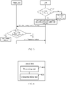
- FIG. 2 is a schematic flow chart of a charging method 200 of one embodiment of the present application. It should be understood that the steps or operations in FIG. 2 are only examples and that embodiments of the present application may also execute other operations or variations of the various operations of FIG. 2 . Further, the steps in FIG. 2 may be executed in a different order than those presented in FIG. 2 , and it is possible that not all of the operations in FIG. 2 are to be executed.
- the BMS in the method 200 may be, for example, the BMS 10 in FIG. 1
- the charging pile may be, for example, the charging pile 20 in FIG. 1 .
- the method 200 will be described below with an electric vehicle as an example, but it should be understood that the application is not limited thereto.
- the method 200 may include some or all of the following steps.
- step 210 the BMS determines a pulse charging demand parameter based on a battery state parameter of the traction battery.
- the battery state parameter may include, but is not limited to, at least one of the following parameters of the traction battery: a battery temperature, a battery voltage, a battery capacity, and a state of charge (State of Charge, SOC) of the battery.
- the pulse charging demand parameter may include at least one of the following parameters: a pulse current demand, a pulse voltage demand, a pulse direction demand, a pulse frequency demand, a pulse interval demand, and a pulse duration demand.
- the pulse charging demand parameter may include a pulse voltage peak demand value, a pulse current effective value demand value, a pulse current peak demand value, a pulse direction demand, and a pulse frequency demand value.
- the BMS can determine the pulse charging demand parameter according to the battery state parameter of the traction battery and according to the corresponding relationship between the battery state parameter and the pulse charging demand parameter.
- the corresponding relationship between the battery state parameter and the pulse charging demand parameter may be preconfigured on the BMS.
- the corresponding relationship between the battery state parameter and the pulse charging demand parameter can be preconfigured on the BMS in the form of a table, so that the BMS can determine the pulse charging demand parameter by looking up the table internally.
- the corresponding relationship between the battery state parameter and the pulse charging demand parameter can be shown in Table 1, in which the first row is the SOC, the first column is the battery temperature, and A, B, and C are the pulse current demand values.
- BMS can determine the pulse current demand value according to SOC, battery temperature, and Table 1. If the battery temperature is -10°C and SOC is 30%, BMS can determine the pulse current demand value as B.
- Table 1 is an example only, the SOC is not necessarily 0-100%, and the gradient values of battery temperature and SOC are not necessarily as shown in Table 1. It should also be understood that the corresponding relationship between the battery state parameter and the pulse charging demand parameter may be a linear relationship or a nonlinear relationship.
- the corresponding relationship between the battery state parameter and the pulse charging demand parameter may also be obtained by the BMS from other devices.
- BMS can first determine a direct current charging demand parameter according to the battery state parameter, and then determine the pulse charging demand parameter according to the direct current charging demand parameter.
- the direct current charging demand parameter may include at least one of the following parameters: a voltage demand value, a current demand value, and an output mode of the charging pile.
- the output mode of the charging pile is a constant current mode or a constant voltage mode. In the constant voltage mode, the output voltage of the charging pile should satisfy the voltage demand value, and the output current should not exceed the current demand value. In the constant current mode, the output current of the charging pile should satisfy the current demand value, and the output voltage should not exceed the voltage demand value.
- BMS can carry out an internal calculation based on the direct current charging demand parameter, to obtain the pulse charging demand parameter. Alternatively, the BMS may determine the pulse charging demand parameter based on the determined direct current charging demand parameter and the corresponding relationship between the direct current charging demand parameter and the pulse charging demand parameter.
- the BMS may enter the pulse charging mode first, and then judge whether the state of the traction battery satisfies the condition of pulse charging according to the battery state parameter. If the battery state parameter satisfies the condition of pulse charging, the BMS then executes step 210. If the battery state parameters do not satisfy the condition of pulse charging, the BMS switches from a pulse charging mode to a direct current charging mode.
- the pulse charging mode is a charging mode using a pulse-type voltage or a pulse-type current
- the direct current charging mode is a charging mode using a constant voltage or a constant current
- the BMS determines that the state of the traction battery satisfies the condition of pulse charging, and executes step 110.
- the battery state parameter includes the SOC
- the SOC is less than or equal to the SOC threshold
- the BMS determines that the state of the traction battery satisfies the condition of pulse charging, and executes step 110.
- the BMS determines that the state of the traction battery satisfies the condition of pulse charging, and executes step 210.
- thermal management system To solve the problem of charging electric vehicles in a low-temperature environment, most of the traction batteries of electric vehicles in the market are equipped with a thermal management system. When the temperature of the traction battery is too low, the thermal management system can convert a part of electric energy into heat energy, thus heating the whole battery group.
- This preheating method can make the traction battery at a more suitable temperature, based on this, the charging pile then charges the traction battery.
- this preheating method is to charge the traction battery after the temperature of the traction battery is increased.
- the space for increasing the temperature of the traction battery is limited, which makes it impossible to fundamentally solve the problem that the charging time of electric vehicles is too long in a low-temperature environment.
- the configuration of the thermal management system in the traction battery will not only increase the weight of the traction battery, but also increase the cost of the traction battery.
- the power conversion equipment is in a pulse charging mode at a low-temperature environment, that is, the direct current output by the charging pile can be converted into a pulse current, so that the normal charging of the traction battery can be realized.
- the heating device is not disposed in the battery pack, the technical solution can also reduce the weight and cost of the traction battery.
- the BMS determines that the state of the traction battery does not satisfy the condition of pulse charging, and then the BMS switches from the pulse charging mode to the direct current charging mode.
- BMS can enter direct current charging mode first, and then judge whether the state of traction battery satisfies the condition of pulse charging according to the battery state parameter. If the battery state parameter satisfies the condition of pulse charging, the BMS switches from the direct current charging mode to the pulse charging mode. If the battery state parameter does not satisfy the condition of pulse charging, the BMS continues to maintain the direct current charging mode.
- the BMS may determine whether to enter the pulse charging mode or the direct current charging mode according to the battery state parameter.
- step 220 the BMS sends a pulse charging information to the charging pile.
- the pulse charging information includes a pulse charging demand parameter, the pulse charging demand parameter is used to indicate that the charging pile outputs the pulse current, and the pulse current is used for charging the traction battery. That is, the pulse charging demand parameter is used to indicate the pulse charging mode.
- the BMS may send a first message to the charging pile, the contents of which may be as shown in Table 2.
- Table 2 Serial number Content Length Remark 1 Pulse voltage peak demand value (V) 2 bytes 2 Pulse current effective value demand value (A) 2 bytes Unit: A Resolution: 0.1 A/bit Range: -2000A to 2000A Offset: -2000A 3 Pulse current peak demand value 2 bytes Unit: A Resolution: 0.1 A/bit Range: -2000A to 2000A Offset: 2000A 4 Pulse direction demand 1 byte 1: Positive; 2: Negative; 3 bidirectional (positive and negative); Other invalid 5 Pulse frequency demand value 2 bytes Unit: Hz Resolution: 1 Hz/bit Range: 0 to 10000 Hz Offset: 0
- the pulse current of the embodiment of the present application can also be referred to as a pulse current waveform or a pulse charging waveform.
- the charging pile can end the charging process.
- the predetermined time may be 1 second.
- the charging pile can consider that the state of the traction battery reaches the condition of direct current charging, and switch from the pulse charging mode to the direct current charging mode.
- the charging pile can be directly switched to the direct current charging mode.
- the charging pile can send inquiry information to BMS, the inquiry information is used for inquiring whether the state of the traction battery satisfies the condition of direct current charging. If the charging pile receives the determination information sent by the BMS, the charging pile can output direct current to the BMS. If the charging pile receives negative response information (such as negative acknowledgement information) sent by the BMS, the charging pile can immediately end charging.
- BMS can also send a direct current charging demand parameter to the charging pile.
- the first message may include the direct current charging parameter.
- the direct current charging demand parameter may be carried in a battery charging demand (BCL) message, the contents specifically included in the BCL message may be shown in Table 3.
- Table 3 Serial number Content Length 1 Voltage demand (V) 2 bytes 2 Current demand (A) 2 bytes 3 Charging Mode (0 ⁇ 01: Constant Voltage Mode; 0 ⁇ 02: Constant Current Mode) 2 bytes
- the BMS may simultaneously send the BCL message and the first message to the charging pile, or the BMS may first send the first message to the charging pile and then send the BCL message, or the BMS may first send the BCL message to the charging pile and then send the first message, which is not specifically limited in the embodiment of the present application.
- step 230 the charging pile outputs the pulse current to the traction battery according to the pulse charging demand parameter, and the pulse current is used to charge the traction battery.
- the method 200 may further include: during the pulse charging process, the BMS judges in real time whether the state of the traction battery satisfies the condition of pulse charging. If the current state of the traction battery satisfies the condition of pulse charging, the BMS continues to maintain the pulse charging mode. If the current state of the traction battery does not satisfy the condition of pulse charging, the BMS exits the pulse charging mode.
- the BMS may determine at a preset time period whether the state of the traction battery satisfies the condition of pulse charging. For example, the BMS can judge whether the state of the traction battery satisfies the condition of pulse charging every 1s.
- the preset time period may be negotiated between the BMS and the charging pile.
- the preset time period may be self-determined by the BMS.
- the BMS can determine whether the state of the traction battery satisfies the condition of pulse charging when obtaining the battery state parameter. That is to say, BMS judges whether the state of the traction battery satisfies the condition of pulse charging every time it obtains the battery state parameter.
- the BMS can also report pulse charging measurement parameter to the charging pile in real time, the pulse charging measurement parameter can include but not limited to at least one of the following state values: a pulse charging voltage measurement value, a pulse charging current measurement value, a pulse direction, and a pulse frequency measurement value.
- the BMS may send a second message to the charging pile, the second message includes the pulse charging measurement parameter.
- the contents of the second message may be as shown in Table 4.
- the charging pile After receiving the second message, the charging pile can adjust the pulse current output to the traction battery in real time based on the pulse charging measurement parameter. In this way, the charging pile can output the pulse current most suitable for the state of the traction battery at the current time, thus further improving the charging efficiency.
- the charging pile may end the pulse charging of the traction battery.
- the charging pile can immediately end the pulse charging.
- the BMS may also send a battery charge state (Battery Charge State, BCS) message to the charging pile, and the BCS message may include at least one of the following parameters: a charging voltage measurement value, a charging current measurement, a maximum single traction battery voltage and its group number, a current SOC, and an estimated remaining charging time.
- BCS Battery Charge State
- the contents of the BCS message may be as shown in Table 5.
- Table 5 Serial number Content Length 1 Charging voltage measurement value 2 bytes 2 Charging current measurement value 2 bytes 3 Maximum single traction battery voltage and its group number 2 bytes 4 Current SOC 1 byte 5 Estimated remaining charging time 2 bytes
- the BSM can simultaneously send the second message and the BCS message to the charging pile, or the BSM can send the second message first and then send the BCS message, or the BSM can send the BCS message first and then send the second message.
- the charging pile in order to enable the BMS to monitor the pulse current, pulse voltage, and other information output by the charging pile at the current time, the charging pile can send a third message to the BMS, the third message includes a pulse charging voltage output value, a pulse charging current output value, a pulse direction and a pulse frequency output value, etc.
- the contents of the third message are shown in Table 6.
- the BMS may end the pulse charging.
- the BMS can immediately end pulse charging, or the BMS can switch from pulse charging to direct current charging.
- the BMS can also send the direct current charging output parameter to charging pile.
- the third message may include the direct current charging output parameter.
- the direct current charging output parameter may, for example, be carried in a charger charging state (Charger Charging State, CCS) message, and the CCS message may specifically include contents as shown in Table 7, for example.
- the method 200 may further include: if the battery state parameter reaches a parameter threshold, such as a battery temperature is 10°C, the BMS can exit the pulse charging mode. At the same time, the BMS can also send an exit instruction to the charging pile, and the exit instruction is used to indicate the charging pile to exit the pulse charging mode.
- a parameter threshold such as a battery temperature is 10°C
- the exit instruction may include 1 bit, with bit “1" indicating the charging pile to exit the pulse charging mode, and bit “0" indicating the charging pile to maintain the pulse charging mode.
- the exit instruction may include a plurality of bits, indicating the charging pile to exit the pulse charging mode if the plurality of bits are the same, and indicating the charging pile to maintain the pulse charging mode if at least two of the plurality of bits are different.
- FIG. 3 is only intended to assist those skilled in the art in better understanding of the embodiments of the present application, and is not intended to limit the scope of the embodiments of the present application.
- the BMS determines whether to enter the pulse charging mode based on the battery state parameter.
- the BMS compares the battery temperature to a temperature threshold, assuming that the temperature threshold is 5°C. If the battery temperature is less than or equal to 5°C, the BMS determines to enter the pulse charging mode, and executes step 320; and if the battery temperature is greater than 5°C, the BMS enters the direct current charging mode.
- the BMS determines a pulse charging demand parameter based on the battery state parameter.
- the pulse charging demand parameter may include a pulse voltage peak demand value, a pulse current effective value demand value, a pulse current peak demand value, a pulse direction demand, and a pulse frequency demand value.
- the BMS sends the first message and the BCL message to the charging pile.
- the BCL message includes a voltage demand value, a current demand value and a charging mode.
- the charging pile executes step 340; and if the charging pile does not receive the first message and/or the BCL message within 1 second, the charging pile immediately ends charging.
- the charging pile outputs a pulse current to the traction battery according to the pulse charging demand parameter.
- the BMS determines the pulse charging demand parameter according to the battery state parameter of the traction battery, and then the charging pile can output pulse current to the traction battery according to the pulse charging demand parameter sent by BMS, which can avoid the problem that the voltage and current output by the charging pile cannot match the traction battery in some scenarios, thus ensuring normal charging of the traction battery.
- the battery state parameter can best reflect the state of the traction battery, and the pulse current converted according to the battery state parameter can effectively ensure the normal power supply of the traction battery.
- serial number of the above-mentioned processes does not mean the sequence of execution, and the execution sequence of each process should be determined by its function and internal logic, and should not constitute any limitation on the implementation process of the embodiments of the present application.
- the charging method of the embodiment of the present application has been described in detail above, and the power conversion device of the embodiment of the present application will be described below. It should be understood that the power conversion device in the embodiment of the present application may execute the charging method in the embodiment of the present application and has a function of executing the corresponding method.
- FIG. 4 shows a schematic block diagram of a BMS 400 of a traction battery of the embodiments of the present application.
- the BMS 400 may include:
- a processing unit 410 configured to determine a pulse charging demand parameter according to a battery state parameter of the traction battery
- a communication unit 420 configured to send a pulse charging information to a charging pile, the pulse charging information including the pulse charging demand parameter for indicating the charging pile to output a pulse current for charging the traction battery.
- the pulse charging demand parameter includes at least one of the following parameters: a pulse current demand, a pulse voltage demand, a pulse direction demand, a pulse frequency demand, a pulse interval demand and a pulse duration demand.
- the battery state parameter includes at least one of the following parameters of the traction battery: a battery temperature, a battery voltage, a battery capacity, and a state of charge (SOC) of the battery.
- the processing unit 410 is further configured to: determine to enter a pulse charging mode according to the battery state parameter, the pulse charging mode being a charging mode using a pulse-type voltage or a pulse-type current.
- the battery state parameter includes a battery temperature of the traction battery
- the processing unit 410 is specifically configured to: under a condition that the battery temperature is less than or equal to a temperature threshold, determine to enter the pulse charging mode.
- the communication unit 420 is further configured to: under a condition that the battery temperature is greater than the temperature threshold, send an exit indicating information to the charging pile, the exit indicating information is used for indicating the charging pile to exit the pulse charging mode.
- the BMS 400 may implement the corresponding operations of the BMS in the method 200, which will not be repeated here for the sake of brevity.
- FIG. 5 shows a schematic block diagram of a charging pile 500 of the embodiments of the present application.
- the charging pile 500 is used for charging the traction battery, as shown in FIG. 5 , and the charging pile 500 includes:
- a communication unit 510 configured to receive a pulse charging information sent by a battery management system (BMS) of the traction battery, the pulse charging information including a pulse charging demand parameter for indicating the charging pile to output a pulse current for charging the traction battery; and
- BMS battery management system
- a processing unit 520 configured to output the pulse current to the traction battery according to the pulse charging demand parameter.
- the pulse charging demand parameter includes at least one of the following parameters: a pulse current demand, a pulse voltage demand, a pulse direction demand, a pulse frequency demand, a pulse interval demand and a pulse duration demand.
- the pulse charging demand parameter is determined according to a battery state parameter of the traction battery.
- the battery state parameter includes at least one of the following parameters of the traction battery: a battery temperature, a battery voltage, a battery capacity, and a state of charge (SOC) of the battery.
- the communication unit 510 is further configured to: receive exit indicating information sent by the BMS when the battery temperature of the traction battery is greater than the temperature threshold value, and the exit indicating information being used for indicating the charging pile to exit a pulse charging mode, the pulse charging mode being a charging mode using a pulse-type voltage or a pulse-type current.
- the charging pile 500 may implement the corresponding operations of the charging pile in the method 200, which will not be repeated here for the sake of brevity.
- FIG. 6 shows a schematic block diagram of a BMS 600 of a traction battery of another embodiment of the present application.
- the BMS 600 includes a memory 610 and a processor 620.
- the memory 610 is coupled to the processor 620, the memory 610 is configured to store a program instruction, and the processor 620 is configured to call the program instruction stored in the memory 610 to execute the methods of various embodiments of the present application described above.
- FIG. 7 shows a schematic block diagram of a charging pile 700 of another embodiment of the present application.
- the charging pile 700 includes a memory 710 and a processor 720.
- the memory 710 is coupled to the processor 720, the memory 710 is configured to store a program instruction, and the processor 720 is configured to call the program instruction stored in the memory 710 to execute the methods of various embodiments of the present application described above.
- the embodiments of the present application also provide a computer-readable storage medium for storing a computer program for executing the aforementioned methods of various embodiments of the present application.
Landscapes
- Engineering & Computer Science (AREA)
- Power Engineering (AREA)
- Transportation (AREA)
- Mechanical Engineering (AREA)
- Chemical Kinetics & Catalysis (AREA)
- Manufacturing & Machinery (AREA)
- Chemical & Material Sciences (AREA)
- Electrochemistry (AREA)
- General Chemical & Material Sciences (AREA)
- Sustainable Energy (AREA)
- Sustainable Development (AREA)
- Life Sciences & Earth Sciences (AREA)
- Microelectronics & Electronic Packaging (AREA)
- Charge And Discharge Circuits For Batteries Or The Like (AREA)
- Secondary Cells (AREA)
Abstract
Description
- The embodiments of the application relate to the technical field of traction batteries, and more particularly relate to a charging method, a battery management system of a traction battery, and a charging pile.
- With the aggravation of energy shortage and environmental pollution in modern society, electric vehicles, as new energy vehicles, have attracted wide attention from all walks of life. However, the charging problem of the electric vehicle has always been the main factor limiting its development.
- Therefore, how to ensure the effective charging of electric vehicles is an urgent problem to be solved.
- Embodiments of the present application provide a charging method, a battery management system of a traction battery, and a charging pile, which can effectively ensure a normal charging of an electric vehicle.
- In a first aspect, a charging method for charging a traction battery is provided, and the method includes: determining a pulse charging demand parameter according to a battery state parameter of the traction battery; and sending a pulse charging information to a charging pile, the pulse charging information including the pulse charging demand parameter for indicating the charging pile to output a pulse current for charging the traction battery.
- With the above technical solution, BMS determines the pulse charging demand parameter according to the battery state parameter of the traction battery, and then the charging pile can output pulse current to the traction battery according to the pulse charging demand parameter sent by BMS, which can avoid the problem that the voltage and current output by the charging pile cannot match the traction battery in some scenarios, thus ensuring normal charging of the traction battery. In addition, the battery state parameter may best reflect the state of the traction battery, and the pulse current converted according to the battery state parameter can effectively ensure the normal power supply of the traction battery.
- In some possible embodiments, the pulse charging demand parameter includes at least one of the following parameters: a pulse current demand, a pulse voltage demand, a pulse direction demand, a pulse frequency demand, a pulse interval demand, and a pulse duration demand.
- In some possible embodiments, the battery state parameter includes at least one of the following parameters of the traction battery: a battery temperature, a battery voltage, a battery capacity, and a state of charge (SOC) of the battery.
- In some possible embodiments, the method further includes: determining to enter a pulse charging mode according to the battery state parameter, where the pulse charging mode is a charging mode using a pulse-type voltage or a pulse-type current.
- Since the battery state parameter can be a parameter that can best reflect the state of the traction battery, the above technical solution of determining to enter a pulse charging mode according to the battery state parameter can improve the accuracy rate of entering the pulse charging mode.
- In some possible embodiments, the battery state parameter includes: a battery temperature of the traction battery, and the determining to enter a pulse charging mode according to the battery state parameter includes under a condition that the battery temperature is less than or equal to a temperature threshold, determining to enter the pulse charging mode.
- In the low-temperature environment, a power conversion equipment enters the pulse charging mode to convert the direct current output by the charging pile into pulse current, which avoids the problem that the lithium battery cannot be charged in the low-temperature environment. Compared with the traditional way, with the above technical solution, it is not necessary to provide an add-on device in the battery pack to pre-heat the traction battery, so that the charging time can be greatly shortened, the battery temperature can be rapidly increased, and the charging efficiency of the traction battery can be effectively improved. Furthermore, since the heating device is not disposed in the battery pack, the technical solution can also reduce the weight and cost of the traction battery.
- In some possible embodiments, the method further includes: under a condition that the battery temperature is greater than the temperature threshold, sending an exit indicating information to the charging pile, the exit indicating information being used for indicating the charging pile to exit the pulse charging mode.
- In a second aspect, a charging method for charging a traction battery is provided, and the method includes: receiving, by a charging pile, a pulse charging information sent by a battery management system (BMS) of the traction battery, the pulse charging information including a pulse charging demand parameter for indicating the charging pile to output a pulse current for charging the traction battery; and outputting by the charging pile, the pulse current to the traction battery according to the pulse charging demand parameter.
- In some possible embodiments, the pulse charging demand parameter includes at least one of the following parameters: a pulse current demand, a pulse voltage demand, a pulse direction demand, a pulse frequency demand, a pulse interval demand, and a pulse duration demand.
- In some possible embodiments, the pulse charging demand parameter is determined according to a battery state parameter of the traction battery.
- In some possible embodiments, the battery state parameter includes at least one of the following parameters of the traction battery: a battery temperature, a battery voltage, a battery capacity, and a state of charge (SOC) of the battery.
- In some possible embodiments, the method further includes: receiving, by the charging pile, exit indicating information sent by the BMS when the battery temperature of the traction battery is greater than the temperature threshold value, the exit indicating information being used for indicating the charging pile to exit a pulse charging mode, the pulse charging mode being a charging mode using a pulse-type voltage or a pulse-type current.
- In a third aspect, a battery management system of a traction battery is provided, which includes: a processing unit configured to determine a pulse charging demand parameter according to a battery state parameter of the traction battery; and a communication unit configured to send a pulse charging information to a charging pile, the pulse charging information including the pulse charging demand parameter for indicating the charging pile to output a pulse current for charging the traction battery.
- In some possible embodiments, the pulse charging demand parameter includes at least one of the following parameters: a pulse current demand, a pulse voltage demand, a pulse direction demand, a pulse frequency demand, a pulse interval demand, and a pulse duration demand.
- In some possible embodiments, the battery state parameter includes at least one of the following parameters of the traction battery: a battery temperature, a battery voltage, a battery capacity, and a state of charge (SOC) of the battery.
- In some possible embodiments, the processing unit is further configured to: determine to enter a pulse charging mode according to the battery state parameter, the pulse charging mode being a charging mode using a pulse-type voltage or a pulse-type current.
- In some possible embodiments, the battery state parameter includes a battery temperature of the traction battery, the processing unit is specifically configured to: under a condition that the battery temperature is less than or equal to a temperature threshold, determine to enter the pulse charging mode.
- In some possible embodiments, the communication unit is further configured to: under a condition that the battery temperature is greater than the temperature threshold, send an exit indicating information to the charging pile, the exit indicating information being used for indicating the charging pile to exit the pulse charging mode.
- In a fourth aspect, a charging pile for charging a traction battery is provided, which includes: a communication unit configured to receive a pulse charging information sent by a battery management system (BMS) of the traction battery, the pulse charging information including a pulse charging demand parameter for indicating the charging pile to output a pulse current for charging the traction battery; and a processing unit configured to output the pulse current to the traction battery according to the pulse charging demand parameter.
- In some possible embodiments, the pulse charging demand parameter includes at least one of the following parameters: a pulse current demand, a pulse voltage demand, a pulse direction demand, a pulse frequency demand, a pulse interval demand, and a pulse duration demand.
- In some possible embodiments, the pulse charging demand parameter is determined according to a battery state parameter of the traction battery.
- In some possible embodiments, the battery state parameter includes at least one of the following parameters of the traction battery: a battery temperature, a battery voltage, a battery capacity, and a state of charge (SOC) of the battery.
- In some possible embodiments, the communication unit is further configured to: receive exit indicating information sent by the BMS when the battery temperature of the traction battery is greater than the temperature threshold value, and the exit indicating information being used for indicating the charging pile to exit a pulse charging mode, the pulse charging mode being a charging mode using a pulse-type voltage or a pulse-type current.
- In a fifth aspect, a battery management system for a traction battery including a processor and a memory is provided. The memory is configured to store a computer program, and the processor is configured to call and run the computer program stored in the memory to execute the method in the first aspect or respective implementations thereof.
- In a sixth aspect, a charging pile including a processor and a memory is provided. The memory is configured to store a computer program, and the processor is configured to call and run the computer program stored in the memory to execute the method in the first aspect or respective implementations thereof.
- In a seventh aspect, a computer-readable storage medium for storing a computer program for executing the method in the first aspect or respective implementations thereof is provided.
- In an eighth aspect, a computer-readable storage medium for storing a computer program for executing the method in the second aspect or respective implementations thereof is provided.
- In order to more clearly explain the technical solution of the embodiments of the present application, the drawings required for use in the embodiments of the present application will be briefly described below, and it will be apparent that the drawings described below are only some embodiments of the present application, and other drawings may be obtained from the drawings without exerting creative effort by those of ordinary skill in the art.
-
FIG. 1 is a schematic diagram of an application architecture to which a charging method of the embodiments of the present application can be applied. -
FIG. 2 is a schematic flow chart of a charging method of the embodiment of the present application. -
FIG. 3 is a specific schematic flow chart of the charging method shown inFIG. 2 . -
FIG. 4 is a schematic block diagram of a battery management system for a traction battery of the embodiments of the present application. -
FIG. 5 is a schematic block diagram of a charging pile of the embodiments of the present application. -
FIG. 6 is a schematic block diagram of the battery management system of the traction battery of another embodiment of the present application. -
FIG. 7 is a schematic block diagram of the charging pile of another embodiment of the present application. - To make the object, technical solution, and advantages of the embodiments of the present application clearer, the technical solution of the embodiments of the present application will be clearly described in conjunction with the accompanying drawings in the embodiments of the present application, and it will be obvious that the described embodiments are part of the embodiments of the present application, but not all of them. Based on the embodiments in the present application, all other embodiments obtained by those of ordinary skill in the art without exerting creative efforts fall within the scope of protection of the present application.
- Unless otherwise defined, all the technical and scientific terms used herein have the same meanings as are commonly understood by those skilled in the art of the present application. Terms used herein in the description of the present application are for the purpose of describing specific embodiments only and are not intended to limit the present application. The terms "including" and "having" and any variations thereof in the description and claims as well as the drawings of the present application are intended to cover a non-exclusive inclusion. The terms "first", "second", etc. in the description and claims or the above drawings of the present application or the above drawings are used to distinguish different objects and are not used to describe a particular order or primary-secondary relationship.
- The "embodiment" mentioned in the present application means that special features, structures, or characteristics described in conjunction with the embodiments may be included in at least one embodiment of the present application. The occurrence of "embodiment" in various positions in the description does not necessarily refer to the same embodiment, nor is it a separate or alternative embodiment that is mutually exclusive to other embodiments. It is explicitly and implicitly understood by those skilled in the art that the embodiments described herein may be combined with other embodiments.
- In the description of the present application, it should also be noted that unless otherwise expressly specified and limited, the terms "mount", "joint", "connect" and "attach" should be understood in a broad sense, for example, it can be a fixed connection or a detachable connection, or being integrally connected; it can be being directly connected or indirectly connected through an intermediate medium, and it can be an internal communication between two components. The specific meanings of the above terms in the present application may be understood in particular to those of ordinary skill in the art.
- The term "and/or" in this application is simply a description of the association relationship of the associated objects, indicating that three relationships can exist, for example, A and/or B, which can mean: A exists alone, both A and B exist, and B exists alone. In addition, the character "/" in the present application generally indicates an alternative relationship between the front and back associated objects.
- As used in the present application, "multiple" refers to more than two and includes two, similarly, "multiple sets" refers to more than two sets and includes two sets, and "multichip" refers to more than two chips and includes two chips.
- The charging problem of electric vehicles has always been the main factor limiting their development. In some special scenarios, the range of voltage and current that the charging pile can output cannot match that of traction batteries. For example, in the low-temperature scene, the minimum voltage or current that the charging pile can output may also lead to lithium plating during charging, and the traction battery cannot be charged normally. In addition, in some cases, power conversion may be needed between the charging pile and the traction battery, such as voltage change, current change, power state change, current, voltage and power timing change, etc.
- In view of this, the embodiment of the application provides a charging method, which can effectively ensure a normal charging of an electric vehicle.
-
FIG. 1 is a schematic diagram of an application architecture to which a charging method of the embodiments of the present application can be applied, in which the solid line indicates a power line and the dotted line indicates the communication line. The application architecture includes a battery management system (Battery Management System, BMS) 10 and a chargingpile 20, and theBMS 10 can be connected with the chargingpile 20 through the communication line to exchange information with the chargingpile 20. For example, the communication line may be a controller area network (Controller Area Network, CAN) communication line or a daisy-chain communication line. - The
BMS 10 is a BMS of a traction battery, and the traction battery is a battery that provides a power source to a power consumption device. Optionally, the traction battery may be a traction storage battery. In terms of the type of battery, the traction battery may be a lithium-ion battery, a lithium-metal battery, a lead-acid battery, a nickel-cadmium battery, a nickel-hydrogen battery, a lithium-sulfur battery, a lithium-air battery, a sodium-ion battery, and the like, which are not specifically limited in the embodiment of the present application. In terms of battery scale, the traction battery in the embodiment of the present application may be a cell/battery cell, may also be a battery module or a battery pack, which is not specifically limited in the embodiment of the present application. Optionally, the power consumption device may be a vehicle, a ship, a spacecraft, or the like, and the embodiment of the present application is not limited thereto. BMS is a control system to protect the safe use of traction batteries, which implements the functions of charge and discharge management, high voltage control, battery protection, battery data collection, battery status evaluation, and so on. The BMS can be integrated with the traction battery and disposed in the same equipment/device, or the BMS can be disposed outside the traction battery as an independent equipment/device. - The charging
pile 20, also known as a charger, is a device for charging the traction battery. The charging pile can output charging power according to the charging demand ofBMS 10 to charge the traction battery. For example, the chargingpile 20 may output voltage and current in accordance with the required voltage and required current sent by theBMS 10. -
FIG. 2 is a schematic flow chart of acharging method 200 of one embodiment of the present application. It should be understood that the steps or operations inFIG. 2 are only examples and that embodiments of the present application may also execute other operations or variations of the various operations ofFIG. 2 . Further, the steps inFIG. 2 may be executed in a different order than those presented inFIG. 2 , and it is possible that not all of the operations inFIG. 2 are to be executed. - The BMS in the
method 200 may be, for example, theBMS 10 inFIG. 1 , and the charging pile may be, for example, the chargingpile 20 inFIG. 1 . Themethod 200 will be described below with an electric vehicle as an example, but it should be understood that the application is not limited thereto. Themethod 200 may include some or all of the following steps. - In
step 210, the BMS determines a pulse charging demand parameter based on a battery state parameter of the traction battery. - The battery state parameter may include, but is not limited to, at least one of the following parameters of the traction battery: a battery temperature, a battery voltage, a battery capacity, and a state of charge (State of Charge, SOC) of the battery. The pulse charging demand parameter may include at least one of the following parameters: a pulse current demand, a pulse voltage demand, a pulse direction demand, a pulse frequency demand, a pulse interval demand, and a pulse duration demand. For example, the pulse charging demand parameter may include a pulse voltage peak demand value, a pulse current effective value demand value, a pulse current peak demand value, a pulse direction demand, and a pulse frequency demand value.
- In one implementation, the BMS can determine the pulse charging demand parameter according to the battery state parameter of the traction battery and according to the corresponding relationship between the battery state parameter and the pulse charging demand parameter.
- Optionally, the corresponding relationship between the battery state parameter and the pulse charging demand parameter may be preconfigured on the BMS. For example, the corresponding relationship between the battery state parameter and the pulse charging demand parameter can be preconfigured on the BMS in the form of a table, so that the BMS can determine the pulse charging demand parameter by looking up the table internally. For example, the corresponding relationship between the battery state parameter and the pulse charging demand parameter can be shown in Table 1, in which the first row is the SOC, the first column is the battery temperature, and A, B, and C are the pulse current demand values. BMS can determine the pulse current demand value according to SOC, battery temperature, and Table 1. If the battery temperature is -10°C and SOC is 30%, BMS can determine the pulse current demand value as B.
Table 1 0% 10% 20% 30% 40% 50% 60% ... 100% -20°C A A A A A A -10°C A A B B C C 0°C B B B B 10°C B B B B 20°C C c c c 30°C c c c c ... - It should be understood that Table 1 is an example only, the SOC is not necessarily 0-100%, and the gradient values of battery temperature and SOC are not necessarily as shown in Table 1. It should also be understood that the corresponding relationship between the battery state parameter and the pulse charging demand parameter may be a linear relationship or a nonlinear relationship.
- Optionally, the corresponding relationship between the battery state parameter and the pulse charging demand parameter may also be obtained by the BMS from other devices.
- In another implementation, BMS can first determine a direct current charging demand parameter according to the battery state parameter, and then determine the pulse charging demand parameter according to the direct current charging demand parameter.
- Specifically, the direct current charging demand parameter may include at least one of the following parameters: a voltage demand value, a current demand value, and an output mode of the charging pile. The output mode of the charging pile is a constant current mode or a constant voltage mode. In the constant voltage mode, the output voltage of the charging pile should satisfy the voltage demand value, and the output current should not exceed the current demand value. In the constant current mode, the output current of the charging pile should satisfy the current demand value, and the output voltage should not exceed the voltage demand value. BMS can carry out an internal calculation based on the direct current charging demand parameter, to obtain the pulse charging demand parameter. Alternatively, the BMS may determine the pulse charging demand parameter based on the determined direct current charging demand parameter and the corresponding relationship between the direct current charging demand parameter and the pulse charging demand parameter.
- Before
step 210, the BMS may enter the pulse charging mode first, and then judge whether the state of the traction battery satisfies the condition of pulse charging according to the battery state parameter. If the battery state parameter satisfies the condition of pulse charging, the BMS then executesstep 210. If the battery state parameters do not satisfy the condition of pulse charging, the BMS switches from a pulse charging mode to a direct current charging mode. - Where, the pulse charging mode is a charging mode using a pulse-type voltage or a pulse-type current, and the direct current charging mode is a charging mode using a constant voltage or a constant current.
- For example, when the battery state parameter includes the battery temperature, if the battery temperature is less than or equal to a temperature threshold (exemplary, the temperature threshold is 5°C), the BMS determines that the state of the traction battery satisfies the condition of pulse charging, and executes step 110. Alternatively, when the battery state parameter includes the SOC, if the SOC is less than or equal to the SOC threshold, the BMS determines that the state of the traction battery satisfies the condition of pulse charging, and executes step 110. Alternatively, when the battery state parameter includes the battery temperature and SOC, if the battery temperature is less than and/or equal to the temperature threshold and the SOC is less than or equal to the SOC threshold, the BMS determines that the state of the traction battery satisfies the condition of pulse charging, and executes
step 210. - To solve the problem of charging electric vehicles in a low-temperature environment, most of the traction batteries of electric vehicles in the market are equipped with a thermal management system. When the temperature of the traction battery is too low, the thermal management system can convert a part of electric energy into heat energy, thus heating the whole battery group. This preheating method can make the traction battery at a more suitable temperature, based on this, the charging pile then charges the traction battery. However, this preheating method is to charge the traction battery after the temperature of the traction battery is increased. The space for increasing the temperature of the traction battery is limited, which makes it impossible to fundamentally solve the problem that the charging time of electric vehicles is too long in a low-temperature environment. In addition, the configuration of the thermal management system in the traction battery will not only increase the weight of the traction battery, but also increase the cost of the traction battery.
- With the above technical solution, the power conversion equipment is in a pulse charging mode at a low-temperature environment, that is, the direct current output by the charging pile can be converted into a pulse current, so that the normal charging of the traction battery can be realized. Compared with the traditional way, it is not necessary in the embodiment of the present application to provide an add-on device in the battery pack to pre-heat the traction battery, so that the charging time can be greatly shortened, the battery temperature can be rapidly increased, and the charging efficiency of the traction battery can be effectively improved. Furthermore, since the heating device is not disposed in the battery pack, the technical solution can also reduce the weight and cost of the traction battery.
- On the contrary, when the battery state parameter includes the battery temperature, if the battery temperature is greater than the temperature threshold, the BMS determines that the state of the traction battery does not satisfy the condition of pulse charging, and then the BMS switches from the pulse charging mode to the direct current charging mode.
- In another possible implementation, BMS can enter direct current charging mode first, and then judge whether the state of traction battery satisfies the condition of pulse charging according to the battery state parameter. If the battery state parameter satisfies the condition of pulse charging, the BMS switches from the direct current charging mode to the pulse charging mode. If the battery state parameter does not satisfy the condition of pulse charging, the BMS continues to maintain the direct current charging mode.
- In another possible embodiment, after obtaining the battery state parameter, the BMS may determine whether to enter the pulse charging mode or the direct current charging mode according to the battery state parameter.
- In
step 220, the BMS sends a pulse charging information to the charging pile. - The pulse charging information includes a pulse charging demand parameter, the pulse charging demand parameter is used to indicate that the charging pile outputs the pulse current, and the pulse current is used for charging the traction battery. That is, the pulse charging demand parameter is used to indicate the pulse charging mode.
- Illustratively, the BMS may send a first message to the charging pile, the contents of which may be as shown in Table 2.
Table 2 Serial number Content Length Remark 1 Pulse voltage peak demand value (V) 2 bytes 2 Pulse current effective value demand value (A) 2 bytes Unit: A Resolution: 0.1 A/bit Range: -2000A to 2000A Offset: -2000A 3 Pulse current peak demand value 2 bytes Unit: A Resolution: 0.1 A/bit Range: -2000A to 2000A Offset: 2000A 4 Pulse direction demand 1 byte 1: Positive; 2: Negative; 3 bidirectional (positive and negative); Other invalid 5 Pulse frequency demand value 2 bytes Unit: Hz Resolution: 1 Hz/bit Range: 0 to 10000 Hz Offset: 0 - It should be noted that the pulse current of the embodiment of the present application can also be referred to as a pulse current waveform or a pulse charging waveform.
- If the charging pile does not receive the charging information sent by BMS within a predetermined time, the charging pile can end the charging process. Illustratively, the predetermined time may be 1 second.
- Alternatively, the charging pile can consider that the state of the traction battery reaches the condition of direct current charging, and switch from the pulse charging mode to the direct current charging mode. For example, the charging pile can be directly switched to the direct current charging mode. For another example, the charging pile can send inquiry information to BMS, the inquiry information is used for inquiring whether the state of the traction battery satisfies the condition of direct current charging. If the charging pile receives the determination information sent by the BMS, the charging pile can output direct current to the BMS. If the charging pile receives negative response information (such as negative acknowledgement information) sent by the BMS, the charging pile can immediately end charging.
- To better match the current charging protocol, BMS can also send a direct current charging demand parameter to the charging pile. As an example, the first message may include the direct current charging parameter. As another example, the direct current charging demand parameter may be carried in a battery charging demand (BCL) message, the contents specifically included in the BCL message may be shown in Table 3.
Table 3 Serial number Content Length 1 Voltage demand (V) 2 bytes 2 Current demand (A) 2 bytes 3 Charging Mode (0×01: Constant Voltage Mode; 0×02: Constant Current Mode) 2 bytes - Optionally, the BMS may simultaneously send the BCL message and the first message to the charging pile, or the BMS may first send the first message to the charging pile and then send the BCL message, or the BMS may first send the BCL message to the charging pile and then send the first message, which is not specifically limited in the embodiment of the present application.
- In
step 230, the charging pile outputs the pulse current to the traction battery according to the pulse charging demand parameter, and the pulse current is used to charge the traction battery. - Further, the
method 200 may further include: during the pulse charging process, the BMS judges in real time whether the state of the traction battery satisfies the condition of pulse charging. If the current state of the traction battery satisfies the condition of pulse charging, the BMS continues to maintain the pulse charging mode. If the current state of the traction battery does not satisfy the condition of pulse charging, the BMS exits the pulse charging mode. - As an example, the BMS may determine at a preset time period whether the state of the traction battery satisfies the condition of pulse charging. For example, the BMS can judge whether the state of the traction battery satisfies the condition of pulse charging every 1s.
- Optionally, the preset time period may be negotiated between the BMS and the charging pile.
- Optionally, the preset time period may be self-determined by the BMS.
- As another example, the BMS can determine whether the state of the traction battery satisfies the condition of pulse charging when obtaining the battery state parameter. That is to say, BMS judges whether the state of the traction battery satisfies the condition of pulse charging every time it obtains the battery state parameter.
- When the current state of the traction battery satisfies the condition of pulse charging, in order to enable the charging pile monitor the charging process in real time, so that the charging pile can output the best pulse current suitable for charging the traction battery, the BMS can also report pulse charging measurement parameter to the charging pile in real time, the pulse charging measurement parameter can include but not limited to at least one of the following state values: a pulse charging voltage measurement value, a pulse charging current measurement value, a pulse direction, and a pulse frequency measurement value. Optionally, the BMS may send a second message to the charging pile, the second message includes the pulse charging measurement parameter. For example, the contents of the second message may be as shown in Table 4.
Table 4 Serial number Content Length Send options 1 Pulse charging voltage measurement value 2 bytes 2 Pulse charging current peak measurement value 2 bytes Unit: A Resolution: 0.1 A/bit Range: -2000A to 2000A Offset: 2000A 3 Pulse charging current effective value measurement value 2 bytes Unit: A Resolution: 0.1 A/bit Range: -2000A to 2000A Offset: 2000A 4 Pulse direction 1 byte 1: Positive; 2: Negative; 3: Bidirectional (positive and negative); Other invalid 5 Pulse frequency measurement value 2 bytes Unit: Hz Resolution: 1 Hz/bit Range: 0 to 10000 Hz Offset: 0 - After receiving the second message, the charging pile can adjust the pulse current output to the traction battery in real time based on the pulse charging measurement parameter. In this way, the charging pile can output the pulse current most suitable for the state of the traction battery at the current time, thus further improving the charging efficiency.
- If the charging pile does not receive the second message within, for example, 5 seconds, the charging pile may end the pulse charging of the traction battery. For example, the charging pile can immediately end the pulse charging.
- In addition to the first message, the BMS may also send a battery charge state (Battery Charge State, BCS) message to the charging pile, and the BCS message may include at least one of the following parameters: a charging voltage measurement value, a charging current measurement, a maximum single traction battery voltage and its group number, a current SOC, and an estimated remaining charging time. For example, the contents of the BCS message may be as shown in Table 5.
Table 5 Serial number Content Length 1 Charging voltage measurement value 2 bytes 2 Charging current measurement value 2 bytes 3 Maximum single traction battery voltage and its group number 2 bytes 4 Current SOC 1 byte 5 Estimated remaining charging time 2 bytes - Similar to the first message and the BCL message, the BSM can simultaneously send the second message and the BCS message to the charging pile, or the BSM can send the second message first and then send the BCS message, or the BSM can send the BCS message first and then send the second message.
- Furthermore, in the pulse charging process, in order to enable the BMS to monitor the pulse current, pulse voltage, and other information output by the charging pile at the current time, the charging pile can send a third message to the BMS, the third message includes a pulse charging voltage output value, a pulse charging current output value, a pulse direction and a pulse frequency output value, etc. For example, the contents of the third message are shown in Table 6.
Table 6 Serial number Content Length Send options 1 Pulse charging voltage output value 2 bytes 2 Pulse charging peak current output value 2 bytes Unit: A Resolution: 0.1 A/bit Range: -2000A to 2000A Offset: 2000A 3 Pulse charging effective current output value 2 bytes Unit: A Resolution: 0.1 A/bit Range: -2000A to 2000A Offset: 2000A 4 Pulse direction 1 byte 1: Positive; 2: Negative; 3: Bidirectional (positive and negative); Other invalid 5 Pulse frequency output value 2 bytes Unit: Hz Resolution: 1 Hz/bit Range: 0 to 10000 Hz Offset: 0 - Optionally, if the BMS does not receive the third message within a certain period of time, the BMS may end the pulse charging. For example, the BMS can immediately end pulse charging, or the BMS can switch from pulse charging to direct current charging.
- Similarly, in order to better correspond to the current charging protocol, the BMS can also send the direct current charging output parameter to charging pile. As an example, the third message may include the direct current charging output parameter. As another example, the direct current charging output parameter may, for example, be carried in a charger charging state (Charger Charging State, CCS) message, and the CCS message may specifically include contents as shown in Table 7, for example.
Table 7 Serial number Content Length 1 Voltage output value 2 bytes 2 Current output value 2 bytes 3 Accumulated charging time 2 bytes 4 Charging permission (00=paused, 01=allowed) 1 byte - In the embodiments of the present application, the
method 200 may further include: if the battery state parameter reaches a parameter threshold, such as a battery temperature is 10°C, the BMS can exit the pulse charging mode. At the same time, the BMS can also send an exit instruction to the charging pile, and the exit instruction is used to indicate the charging pile to exit the pulse charging mode. - Optionally, the exit instruction may include 1 bit, with bit "1" indicating the charging pile to exit the pulse charging mode, and bit "0" indicating the charging pile to maintain the pulse charging mode. Alternatively, the exit instruction may include a plurality of bits, indicating the charging pile to exit the pulse charging mode if the plurality of bits are the same, and indicating the charging pile to maintain the pulse charging mode if at least two of the plurality of bits are different.
- To more clearly describe embodiments of the present application, a specific implementation process of the
method 200 is described in detail below with reference toFIG. 3 . It should be understood thatFIG. 3 is only intended to assist those skilled in the art in better understanding of the embodiments of the present application, and is not intended to limit the scope of the embodiments of the present application. - In 310, the BMS determines whether to enter the pulse charging mode based on the battery state parameter.
- For example, the BMS compares the battery temperature to a temperature threshold, assuming that the temperature threshold is 5°C. If the battery temperature is less than or equal to 5°C, the BMS determines to enter the pulse charging mode, and executes
step 320; and if the battery temperature is greater than 5°C, the BMS enters the direct current charging mode. - In 320, the BMS determines a pulse charging demand parameter based on the battery state parameter.
- Where the pulse charging demand parameter may include a pulse voltage peak demand value, a pulse current effective value demand value, a pulse current peak demand value, a pulse direction demand, and a pulse frequency demand value.
- In 330, the BMS sends the first message and the BCL message to the charging pile.
- Where the first message includes a pulse charging demand parameter, and the BCL message includes a voltage demand value, a current demand value and a charging mode.
- If the charging pile receives the first message and/or the BCL message within 1 second, the charging pile executes
step 340; and if the charging pile does not receive the first message and/or the BCL message within 1 second, the charging pile immediately ends charging. - In 340, the charging pile outputs a pulse current to the traction battery according to the pulse charging demand parameter.
- According to the embodiments of the present application, the BMS determines the pulse charging demand parameter according to the battery state parameter of the traction battery, and then the charging pile can output pulse current to the traction battery according to the pulse charging demand parameter sent by BMS, which can avoid the problem that the voltage and current output by the charging pile cannot match the traction battery in some scenarios, thus ensuring normal charging of the traction battery. In addition, the battery state parameter can best reflect the state of the traction battery, and the pulse current converted according to the battery state parameter can effectively ensure the normal power supply of the traction battery.
- In the embodiments of the present application, the serial number of the above-mentioned processes does not mean the sequence of execution, and the execution sequence of each process should be determined by its function and internal logic, and should not constitute any limitation on the implementation process of the embodiments of the present application.
- Moreover, on the premise of no conflict, each embodiment described in the present application and/or the technical features in each embodiment can be arbitrarily combined with each other, and the technical solution obtained after combination should also fall within the scope of protection of the present application.
- The charging method of the embodiment of the present application has been described in detail above, and the power conversion device of the embodiment of the present application will be described below. It should be understood that the power conversion device in the embodiment of the present application may execute the charging method in the embodiment of the present application and has a function of executing the corresponding method.
-
FIG. 4 shows a schematic block diagram of aBMS 400 of a traction battery of the embodiments of the present application. As shown inFIG. 4 , theBMS 400 may include: - a
processing unit 410 configured to determine a pulse charging demand parameter according to a battery state parameter of the traction battery; - a
communication unit 420 configured to send a pulse charging information to a charging pile, the pulse charging information including the pulse charging demand parameter for indicating the charging pile to output a pulse current for charging the traction battery. - Optionally, in the embodiment of the present application, the pulse charging demand parameter includes at least one of the following parameters: a pulse current demand, a pulse voltage demand, a pulse direction demand, a pulse frequency demand, a pulse interval demand and a pulse duration demand.
- Optionally, in the embodiments of the present application, the battery state parameter includes at least one of the following parameters of the traction battery: a battery temperature, a battery voltage, a battery capacity, and a state of charge (SOC) of the battery.
- Optionally, in the embodiment of the present application, the
processing unit 410 is further configured to: determine to enter a pulse charging mode according to the battery state parameter, the pulse charging mode being a charging mode using a pulse-type voltage or a pulse-type current. - Optionally, in the embodiment of the present application, the battery state parameter includes a battery temperature of the traction battery, the
processing unit 410 is specifically configured to: under a condition that the battery temperature is less than or equal to a temperature threshold, determine to enter the pulse charging mode. - Optionally, in the embodiment of the present application, the
communication unit 420 is further configured to: under a condition that the battery temperature is greater than the temperature threshold, send an exit indicating information to the charging pile, the exit indicating information is used for indicating the charging pile to exit the pulse charging mode. - It should be understood that the
BMS 400 may implement the corresponding operations of the BMS in themethod 200, which will not be repeated here for the sake of brevity. -
FIG. 5 shows a schematic block diagram of a chargingpile 500 of the embodiments of the present application. The chargingpile 500 is used for charging the traction battery, as shown inFIG. 5 , and the chargingpile 500 includes: - a
communication unit 510 configured to receive a pulse charging information sent by a battery management system (BMS) of the traction battery, the pulse charging information including a pulse charging demand parameter for indicating the charging pile to output a pulse current for charging the traction battery; and - a
processing unit 520 configured to output the pulse current to the traction battery according to the pulse charging demand parameter. - Optionally, in the embodiment of the present application, the pulse charging demand parameter includes at least one of the following parameters: a pulse current demand, a pulse voltage demand, a pulse direction demand, a pulse frequency demand, a pulse interval demand and a pulse duration demand.
- Optionally, in the embodiments of the present application, the pulse charging demand parameter is determined according to a battery state parameter of the traction battery.
- Optionally, in the embodiments of the present application, the battery state parameter includes at least one of the following parameters of the traction battery: a battery temperature, a battery voltage, a battery capacity, and a state of charge (SOC) of the battery.
- Optionally, in the embodiments of the present application, the
communication unit 510 is further configured to: receive exit indicating information sent by the BMS when the battery temperature of the traction battery is greater than the temperature threshold value, and the exit indicating information being used for indicating the charging pile to exit a pulse charging mode, the pulse charging mode being a charging mode using a pulse-type voltage or a pulse-type current. - It should be understood that the charging
pile 500 may implement the corresponding operations of the charging pile in themethod 200, which will not be repeated here for the sake of brevity. -
FIG. 6 shows a schematic block diagram of aBMS 600 of a traction battery of another embodiment of the present application. As shown inFIG. 6 , theBMS 600 includes amemory 610 and aprocessor 620. Thememory 610 is coupled to theprocessor 620, thememory 610 is configured to store a program instruction, and theprocessor 620 is configured to call the program instruction stored in thememory 610 to execute the methods of various embodiments of the present application described above. -
FIG. 7 shows a schematic block diagram of a chargingpile 700 of another embodiment of the present application. As shown inFIG. 7 , the chargingpile 700 includes amemory 710 and aprocessor 720. Thememory 710 is coupled to theprocessor 720, thememory 710 is configured to store a program instruction, and theprocessor 720 is configured to call the program instruction stored in thememory 710 to execute the methods of various embodiments of the present application described above. - The embodiments of the present application also provide a computer-readable storage medium for storing a computer program for executing the aforementioned methods of various embodiments of the present application. Finally, it should be noted that the above embodiments are only used to illustrate the technical solution of the present application, not to limit it. Although the present application has been described in detail with reference to the foregoing embodiments, it will be understood by those of ordinary skill in the art that modifications may still be made to the technical solution described in the foregoing embodiments, or some technical features thereof may be equivalently replaced, but such modifications or replacements do not depart the essence of the corresponding technical solution from the spirit and scope of the technical solution of the various embodiments of the present application.
Claims (22)
- A charging method for charging a traction battery, the method comprising:determining a pulse charging demand parameter according to a battery state parameter of the traction battery; andsending a pulse charging information to a charging pile, the pulse charging information comprising the pulse charging demand parameter for indicating the charging pile to output a pulse current for charging the traction battery.
- The method according to claim 1, wherein the pulse charging demand parameter comprises at least one of the following parameters: a pulse current demand, a pulse voltage demand, a pulse direction demand, a pulse frequency demand, a pulse interval demand and a pulse duration demand.
- The method according to claim 1 or 2, wherein the battery state parameter comprises at least one of the following parameters of the traction battery: a battery temperature, a battery voltage, a battery capacity, and a state of charge (SOC) of the battery.
- The method according to claim 1 or 2, wherein the method further comprises:determining to enter a pulse charging mode according to the battery state parameter,wherein the pulse charging mode is a charging mode using a pulse-type voltage or a pulse-type current.
- The method according to claim 4, wherein the battery state parameter comprises a battery temperature of the traction battery, andthe determining to enter a pulse charging mode according to the battery state parameter comprises:under a condition that the battery temperature is less than or equal to a temperature threshold, determining to enter the pulse charging mode.
- The method according to claim 5, wherein the method further comprises:
under a condition that the battery temperature is greater than the temperature threshold, sending an exit indicating information to the charging pile, the exit indicating information being used for indicating the charging pile to exit the pulse charging mode. - A charging method for charging a traction battery, the method comprising:receiving, by a charging pile, a pulse charging information sent by a battery management system (BMS) of the traction battery, the pulse charging information comprising a pulse charging demand parameter for indicating the charging pile to output a pulse current for charging the traction battery; andoutputting, by the charging pile, the pulse current to the traction battery according to the pulse charging demand parameter.
- The method according to claim 7, wherein the pulse charging demand parameter comprises at least one of the following parameters: a pulse current demand, a pulse voltage demand, a pulse direction demand, a pulse frequency demand, a pulse interval demand and a pulse duration demand.
- The method according to claim 7 or 8, wherein the pulse charging demand parameter is determined according to a battery state parameter of the traction battery.
- The method according to claim 9, wherein the battery state parameter comprises at least one of the following parameters of the traction battery: a battery temperature, a battery voltage, a battery capacity, and a state of charge (SOC) of the battery.
- The method according to claim 7 or 8, wherein the method further comprises:
receiving, by the charging pile, exit indicating information sent by the BMS when a battery temperature of the traction battery is greater than a temperature threshold value, and the exit indicating information being used for indicating the charging pile to exit a pulse charging mode, the pulse charging mode being a charging mode using a pulse-type voltage or a pulse-type current. - A battery management system of a traction battery, the battery management system comprising:a processing unit configured to determine a pulse charging demand parameter according to a battery state parameter of the traction battery;a communication unit configured to send a pulse charging information to a charging pile, the pulse charging information comprising the pulse charging demand parameter for indicating the charging pile to output a pulse current for charging the traction battery.
- The battery management system according to claim 12, wherein the pulse charging demand parameter comprises at least one of the following parameters: a pulse current demand, a pulse voltage demand, a pulse direction demand, a pulse frequency demand, a pulse interval demand and a pulse duration demand.
- The battery management system according to claim 12 or 13, wherein the battery state parameter comprises at least one of the following parameters of the traction battery: a battery temperature, a battery voltage, a battery capacity, and a state of charge (SOC) of the battery.
- The battery management system according to claim 12 or 13, wherein processing unit is further configured to:
determine to enter a pulse charging mode according to the battery state parameter, the pulse charging mode being a charging mode using a pulse-type voltage or a pulse-type current. - The battery management system according to claim 15, wherein the battery state parameter comprises a battery temperature of the traction battery, the processing unit is specifically configured to:
under a condition that the battery temperature is less than or equal to a temperature threshold, determine to enter the pulse charging mode. - The battery management system according to claim 15, wherein the communication unit is further configured to:
under a condition that the battery temperature is greater than the temperature threshold, send an exit indicating information to the charging pile, the exit indicating information being used for indicating the charging pile to exit the pulse charging mode. - A charging pile for charging a traction battery, the charging pile comprising:a communication unit configured to receive a pulse charging information sent by a battery management system (BMS) of the traction battery, the pulse charging information comprising a pulse charging demand parameter for indicating the charging pile to output a pulse current for charging the traction battery; anda processing unit configured to output the pulse current to the traction battery according to the pulse charging demand parameter.
- The charging pile according to claim 18, wherein the pulse charging demand parameter comprises at least one of the following parameters: a pulse current demand, a pulse voltage demand, a pulse direction demand, a pulse frequency demand, a pulse interval demand and a pulse duration demand.
- The charging pile according to claim 18 or 19, wherein the pulse charging demand parameter is determined according to a battery state parameter of the traction battery.
- The charging pile according to claim 20, wherein the battery state parameter comprises at least one of the following parameters of the traction battery: a battery temperature, a battery voltage, a battery capacity, and a state of charge (SOC) of the battery.
- The charging pile according to claim 18 or 19, wherein the communication unit is further configured to:
receive exit indicating information sent by the BMS when a battery temperature of the traction battery is greater than a temperature threshold value, the exit indicating information being used for indicating the charging pile to exit a pulse charging mode, the pulse charging mode being a charging mode using a pulse-type voltage or a pulse-type current.
Applications Claiming Priority (1)
| Application Number | Priority Date | Filing Date | Title |
|---|---|---|---|
| PCT/CN2021/074181 WO2022160188A1 (en) | 2021-01-28 | 2021-01-28 | Charging method, battery management system of power battery, and charging pile |
Publications (2)
| Publication Number | Publication Date |
|---|---|
| EP4064411A4 EP4064411A4 (en) | 2022-09-28 |
| EP4064411A1 true EP4064411A1 (en) | 2022-09-28 |
Family
ID=82652854
Family Applications (1)
| Application Number | Title | Priority Date | Filing Date |
|---|---|---|---|
| EP21815873.1A Pending EP4064411A1 (en) | 2021-01-28 | 2021-01-28 | Charging method, battery management system of power battery, and charging pile |
Country Status (6)
| Country | Link |
|---|---|
| US (1) | US12095301B2 (en) |
| EP (1) | EP4064411A1 (en) |
| JP (1) | JP7383058B2 (en) |
| KR (1) | KR20220112178A (en) |
| CN (1) | CN115836424A (en) |
| WO (1) | WO2022160188A1 (en) |
Families Citing this family (3)
| Publication number | Priority date | Publication date | Assignee | Title |
|---|---|---|---|---|
| JP7394888B2 (en) * | 2021-01-28 | 2023-12-08 | 寧徳時代新能源科技股▲分▼有限公司 | Charging method and power conversion device |
| WO2022160190A1 (en) * | 2021-01-28 | 2022-08-04 | 宁德时代新能源科技股份有限公司 | Charging method, battery management system for traction battery, and charging pile |
| EP4135149B1 (en) * | 2021-06-17 | 2024-09-04 | Contemporary Amperex Technology Co., Limited | Charging control method and apparatus and readable storage medium |
Family Cites Families (76)
| Publication number | Priority date | Publication date | Assignee | Title |
|---|---|---|---|---|
| US4389608A (en) * | 1981-09-30 | 1983-06-21 | Dahl Ernest A | Transformerless battery controlled battery charger |
| US5525892A (en) * | 1993-08-24 | 1996-06-11 | Pulse Charge Systems, Inc. | Pulsed battery rejuvenator having variable trailing edge shaped pulses |
| US5633574A (en) * | 1994-01-18 | 1997-05-27 | Sage; George E. | Pulse-charge battery charger |
| US5548200A (en) * | 1994-07-06 | 1996-08-20 | Norvik Traction Inc. | Universal charging station and method for charging electric vehicle batteries |
| JP3228097B2 (en) * | 1995-10-19 | 2001-11-12 | 株式会社日立製作所 | Charging system and electric vehicle |
| JPH10210675A (en) * | 1997-01-20 | 1998-08-07 | Yamaha Motor Co Ltd | Charge control method and charge controller |
| US5773955A (en) * | 1997-03-11 | 1998-06-30 | Northrop Grumman Corporation | Battery charger apparatus |
| US6137265A (en) * | 1999-01-11 | 2000-10-24 | Dell Usa, L.P. | Adaptive fast charging of lithium-ion batteries |
| JP2002125326A (en) | 2000-10-12 | 2002-04-26 | Honda Motor Co Ltd | Battery charge control method |
| JP5316831B2 (en) * | 2006-02-28 | 2013-10-16 | 日立工機株式会社 | Cordless power tool or charger |
| ITMI20061296A1 (en) * | 2006-07-04 | 2008-01-05 | Campagnolo Srl | METHOD OF CONTROL AND SYSTEM OF CHARGING A BATTERY POWER UNIT |
| US8493024B2 (en) * | 2007-06-06 | 2013-07-23 | Wfk & Associates, Llc | Apparatus for pulse charging electric vehicles |
| CN101154821A (en) * | 2007-09-21 | 2008-04-02 | 中兴通讯股份有限公司 | Quick charging device and method for nickel-hydrogen battery |
| CN101789612A (en) * | 2009-01-23 | 2010-07-28 | 刘允钊 | Multi-purpose car charging device and charging method thereof |
| WO2010126894A1 (en) * | 2009-04-30 | 2010-11-04 | Alevo, Inc. | Vehicle utility communication system |
| JP5446461B2 (en) | 2009-05-25 | 2014-03-19 | トヨタ自動車株式会社 | Secondary battery charging method and charging system, vehicle, and charging equipment |
| WO2011007573A1 (en) * | 2009-07-15 | 2011-01-20 | パナソニック株式会社 | Power control system, method, device and program |
| DE102010028626B4 (en) * | 2010-05-05 | 2021-09-16 | Bender Gmbh & Co. Kg | Electric vehicle charging device |
| US11397216B2 (en) * | 2010-05-21 | 2022-07-26 | Qnovo Inc. | Battery adaptive charging using a battery model |
| US11397215B2 (en) * | 2010-05-21 | 2022-07-26 | Qnovo Inc. | Battery adaptive charging using battery physical phenomena |
| US8698458B2 (en) * | 2010-07-08 | 2014-04-15 | Samsung Sdi Co., Ltd. | Battery pack having boosting charge function and method thereof |
| CN101902043B (en) * | 2010-07-23 | 2014-06-04 | 中兴通讯股份有限公司 | Charging circuit management device and wireless terminal |
| US8334675B2 (en) * | 2010-07-28 | 2012-12-18 | Honda Motor Co., Ltd. | Method of charging battery based on calcualtion of an ion concentration of a solid active material and battery charging control system |
| WO2012040369A2 (en) * | 2010-09-21 | 2012-03-29 | Proterra Inc. | Systems and methods for equivalent rapid charging with different energy storage configurations |
| CN101969218A (en) * | 2010-10-29 | 2011-02-09 | 重庆长安汽车股份有限公司 | Intelligent charging method for pure electric automobile |
| CN102468656B (en) * | 2010-11-04 | 2014-07-16 | 凹凸电子(武汉)有限公司 | Charging control device, method and battery management system |
| CN202019221U (en) * | 2011-04-18 | 2011-10-26 | 成都秦川科技发展有限公司 | PWM (Pulse-Width Modulation) rectifying and variable-voltage variable-current pulse charging system for electric vehicle |
| WO2014151976A2 (en) * | 2013-03-14 | 2014-09-25 | Evgentech, Inc. | Pulse battery charger methods and systems for improved charging of lithium ion batteries |
| CN104249629B (en) * | 2013-06-28 | 2016-09-07 | 比亚迪股份有限公司 | Electric automobile, the dynamical system of electric automobile and the charging method of electrokinetic cell |
| US8907631B1 (en) * | 2013-07-31 | 2014-12-09 | Qnovo Inc. | Adaptive charging technique and circuitry for a battery/cell using multiple charge circuits and temperature data |
| CN104347896B (en) * | 2013-08-07 | 2020-02-14 | 荣盛盟固利新能源科技有限公司 | Method for improving service life of lithium ion battery in low-temperature environment |
| US9331364B2 (en) * | 2014-02-04 | 2016-05-03 | Nissan North America, Inc. | Lithium sulfur battery pulse charging method and pulse waveform |
| ES2856686T3 (en) * | 2014-07-28 | 2021-09-28 | Ec Power Llc | Systems and Methods for Rapidly Charging Batteries at Low Temperatures |
| KR102207324B1 (en) * | 2014-08-04 | 2021-01-27 | 현대모비스 주식회사 | Interface for wireless power transmission device |
| KR20160038352A (en) * | 2014-09-30 | 2016-04-07 | 현대모비스 주식회사 | Interface between personal terminal and wireless power transmission device |
| KR102312409B1 (en) * | 2014-11-10 | 2021-10-13 | 현대모비스 주식회사 | System and method for guiding wireless charging of vehicle |
| CN105703022B (en) * | 2014-11-27 | 2018-03-20 | 中信国安盟固利动力科技有限公司 | A kind of lithium-ion-power cell charging method based on temperature control cell decay |
| US9991726B2 (en) * | 2015-01-12 | 2018-06-05 | Potential Difference, Inc. | Rapid battery charging |
| US10193366B2 (en) * | 2015-01-12 | 2019-01-29 | Potential Difference, Inc. | Rapid battery charging |
| US10611251B2 (en) * | 2015-11-13 | 2020-04-07 | Nio Usa, Inc. | Distributed processing network for rechargeable electric vehicle tracking and routing |
| CN105680541B (en) * | 2016-03-28 | 2017-11-03 | 西安特锐德智能充电科技有限公司 | A kind of charging method of low temperature charging strategy |
| JP6455497B2 (en) * | 2016-11-16 | 2019-01-23 | トヨタ自動車株式会社 | Vehicle battery system and control method thereof |
| US10195948B2 (en) * | 2017-03-07 | 2019-02-05 | Textron Innovations Inc. | Controlling charge on a lithium battery of a utility vehicle |
| CN110546852B (en) * | 2017-04-27 | 2023-07-14 | 松下知识产权经营株式会社 | Power supply device, power storage system, and charging method |
| US20180339601A1 (en) * | 2017-05-23 | 2018-11-29 | Martin Kruszelnicki | Charging station system and method |
| US20180339597A1 (en) * | 2017-05-23 | 2018-11-29 | Martin Kruszelnicki | Charging connector |
| CN107394294B (en) | 2017-07-20 | 2018-09-04 | 浙江谷神能源科技股份有限公司 | For the systems of lithium ion battery charge and discharge, control device and associated method |
| DE102017218263A1 (en) * | 2017-10-12 | 2019-04-18 | Robert Bosch Gmbh | Method for charging an electrical energy store |
| JP2019117685A (en) | 2017-10-25 | 2019-07-18 | ゼジャン・ゴッドセンド・パワー・テクノロジー・カンパニー・リミテッド | System and control device for charging and discharging lithium ion battery, and relevant method |
| CN108878996B (en) * | 2018-05-22 | 2021-03-23 | 宁德时代新能源科技股份有限公司 | Battery pack system, control method thereof and management equipment |
| DE102018121530A1 (en) * | 2018-09-04 | 2020-03-05 | Borgward Trademark Holdings Gmbh | Method and device for determining the remaining charging time, and electric vehicle |
| US11817731B2 (en) * | 2018-10-12 | 2023-11-14 | Briggs & Stratton, Llc | Battery assembly for battery powered equipment |
| US20200139845A1 (en) * | 2018-11-07 | 2020-05-07 | Trapeze Software Group Inc. | Battery state monitoring system and method therefor |
| US10933767B2 (en) * | 2019-01-04 | 2021-03-02 | Hyundai Motor Company | Electric vehicle energy sharing marketplace |
| JP6719853B1 (en) | 2019-03-25 | 2020-07-08 | マレリ株式会社 | Charge control device, charge control method, and charge control program |
| JP7263116B2 (en) * | 2019-05-20 | 2023-04-24 | サンデン株式会社 | TEMPERATURE ADJUSTMENT DEVICE FOR ON-BOARD DEVICE AND VEHICLE AIR CONDITIONING DEVICE INCLUDING THE SAME |
| CN110970691B (en) * | 2019-05-28 | 2021-10-22 | 宁德时代新能源科技股份有限公司 | Heating method, control unit and heating circuit of rechargeable battery |
| US11177676B2 (en) * | 2019-06-25 | 2021-11-16 | Ford Global Technologies, Llc | Systems and methods for fast charging batteries using intermittent discharge pulses |
| DE102019117944A1 (en) * | 2019-07-03 | 2021-01-07 | Dr. Ing. H.C. F. Porsche Aktiengesellschaft | Method and device for charging a vehicle battery |
| CN111211595B (en) * | 2020-01-14 | 2021-11-09 | 北京小米移动软件有限公司 | Charging method and device, electronic equipment and storage medium |
| KR20220003384A (en) * | 2020-07-01 | 2022-01-10 | 현대자동차주식회사 | Charging device and methid for battery of vehicle |
| EP3968489A1 (en) * | 2020-09-11 | 2022-03-16 | ads-tec Energy GmbH | Battery module |
| CN112260372B (en) * | 2020-12-23 | 2021-04-27 | 江苏时代新能源科技有限公司 | Battery equalization method and device and battery management system |
| JP7394888B2 (en) * | 2021-01-28 | 2023-12-08 | 寧徳時代新能源科技股▲分▼有限公司 | Charging method and power conversion device |
| CN115803983B (en) * | 2021-01-28 | 2024-02-02 | 宁德时代新能源科技股份有限公司 | Method for pre-charging a power conversion device and power conversion device |
| CN115777070A (en) * | 2021-01-28 | 2023-03-10 | 宁德时代新能源科技股份有限公司 | Method and device for detecting lithium battery abnormity, battery management system and battery system |
| EP4064536A4 (en) * | 2021-01-28 | 2022-09-28 | Contemporary Amperex Technology Co., Limited | Power supply control method for power conversion device, and power conversion device |
| HUE064052T2 (en) * | 2021-01-28 | 2024-02-28 | Contemporary Amperex Technology Co Ltd | Power conversion device precharging method and power conversion device |
| CN115699505A (en) * | 2021-01-28 | 2023-02-03 | 宁德时代新能源科技股份有限公司 | Charging method and power conversion device |
| WO2022160190A1 (en) * | 2021-01-28 | 2022-08-04 | 宁德时代新能源科技股份有限公司 | Charging method, battery management system for traction battery, and charging pile |
| WO2022170481A1 (en) * | 2021-02-09 | 2022-08-18 | 宁德时代新能源科技股份有限公司 | Battery charging method, controller, battery management system, battery, and electric apparatus |
| EP4135149B1 (en) * | 2021-06-17 | 2024-09-04 | Contemporary Amperex Technology Co., Limited | Charging control method and apparatus and readable storage medium |
| SE2150806A1 (en) * | 2021-06-22 | 2022-12-23 | Ctek Sweden Ab | Method for communication between a battery charger and an electrically connected vehicle |
| US11390178B1 (en) * | 2021-08-20 | 2022-07-19 | Beta Air, Llc | Connector and method for use for authorizing battery charging for an electric vehicle |
| US11485517B1 (en) * | 2021-08-20 | 2022-11-01 | Beta Air, Llc | System and method for communicating a pre-charging package stream of an electric aircraft |
| CN116568551A (en) * | 2021-08-31 | 2023-08-08 | 宁德时代新能源科技股份有限公司 | Charging management method, battery exchange cabinet and system for battery exchange station |
-
2021
- 2021-01-28 EP EP21815873.1A patent/EP4064411A1/en active Pending
- 2021-01-28 WO PCT/CN2021/074181 patent/WO2022160188A1/en unknown
- 2021-01-28 CN CN202180045548.6A patent/CN115836424A/en active Pending
- 2021-01-28 KR KR1020217039639A patent/KR20220112178A/en active Search and Examination
- 2021-01-28 JP JP2021575017A patent/JP7383058B2/en active Active
-
2022
- 2022-11-04 US US17/980,860 patent/US12095301B2/en active Active
Also Published As
| Publication number | Publication date |
|---|---|
| US12095301B2 (en) | 2024-09-17 |
| CN115836424A (en) | 2023-03-21 |
| JP7383058B2 (en) | 2023-11-17 |
| KR20220112178A (en) | 2022-08-10 |
| WO2022160188A1 (en) | 2022-08-04 |
| US20230076134A1 (en) | 2023-03-09 |
| EP4064411A4 (en) | 2022-09-28 |
| JP2023514886A (en) | 2023-04-12 |
Similar Documents
| Publication | Publication Date | Title |
|---|---|---|
| EP4064509A1 (en) | Charging method and power conversion device | |
| EP4064411A1 (en) | Charging method, battery management system of power battery, and charging pile | |
| EP4064413A1 (en) | Charging method, battery management system for traction battery, and charging pile | |
| EP4071885A1 (en) | Battery charging method, controller, battery management system, battery, and electric apparatus | |
| CN111987759B (en) | Active equalization topology and method based on high-frequency power electronic transformer | |
| JP7394888B2 (en) | Charging method and power conversion device | |
| Min et al. | Inner supply data transmission in quasi-resonant flyback converters for Li-ion battery applications using multiplexing mode | |
| KR102644604B1 (en) | Charge/discharge device, battery charging method, and charge/discharge system | |
| CN115986233A (en) | Battery cluster, energy storage system, uninterrupted power source system and electric automobile | |
| US12051934B2 (en) | Method for charging battery, charging and discharging device | |
| US20230034292A1 (en) | Charging and discharging apparatus, method for charging battery and charging and discharging system | |
| KR20230019380A (en) | Charging and discharging device and battery charging method | |
| WO2023029048A1 (en) | Battery heating device, and control method, control circuit and power device therefor | |
| EP4123868A2 (en) | Battery pack | |
| KR20230019401A (en) | Battery charging method, battery management system and charging/discharging device | |
| CN117856383A (en) | Battery energy storage system, energy control method, device and medium |
Legal Events
| Date | Code | Title | Description |
|---|---|---|---|
| STAA | Information on the status of an ep patent application or granted ep patent |
Free format text: STATUS: UNKNOWN |
|
| STAA | Information on the status of an ep patent application or granted ep patent |
Free format text: STATUS: THE INTERNATIONAL PUBLICATION HAS BEEN MADE |
|
| PUAI | Public reference made under article 153(3) epc to a published international application that has entered the european phase |
Free format text: ORIGINAL CODE: 0009012 |
|
| STAA | Information on the status of an ep patent application or granted ep patent |
Free format text: STATUS: REQUEST FOR EXAMINATION WAS MADE |
|
| 17P | Request for examination filed |
Effective date: 20211209 |
|
| A4 | Supplementary search report drawn up and despatched |
Effective date: 20220711 |
|
| AK | Designated contracting states |
Kind code of ref document: A1 Designated state(s): AL AT BE BG CH CY CZ DE DK EE ES FI FR GB GR HR HU IE IS IT LI LT LU LV MC MK MT NL NO PL PT RO RS SE SI SK SM TR |
|
| STAA | Information on the status of an ep patent application or granted ep patent |
Free format text: STATUS: EXAMINATION IS IN PROGRESS |
|
| 17Q | First examination report despatched |
Effective date: 20231108 |
|
| DAV | Request for validation of the european patent (deleted) | ||
| DAX | Request for extension of the european patent (deleted) |