EP4064201A2 - Schnittpunktprüfung in einem strahlverfolgungssystem - Google Patents
Schnittpunktprüfung in einem strahlverfolgungssystem Download PDFInfo
- Publication number
- EP4064201A2 EP4064201A2 EP22163161.7A EP22163161A EP4064201A2 EP 4064201 A2 EP4064201 A2 EP 4064201A2 EP 22163161 A EP22163161 A EP 22163161A EP 4064201 A2 EP4064201 A2 EP 4064201A2
- Authority
- EP
- European Patent Office
- Prior art keywords
- ray
- edge
- sign
- polygon
- vertices
- Prior art date
- Legal status (The legal status is an assumption and is not a legal conclusion. Google has not performed a legal analysis and makes no representation as to the accuracy of the status listed.)
- Granted
Links
Images






Classifications
-
- G—PHYSICS
- G06—COMPUTING OR CALCULATING; COUNTING
- G06T—IMAGE DATA PROCESSING OR GENERATION, IN GENERAL
- G06T15/00—Three-dimensional [3D] image rendering
- G06T15/06—Ray-tracing
-
- G—PHYSICS
- G06—COMPUTING OR CALCULATING; COUNTING
- G06T—IMAGE DATA PROCESSING OR GENERATION, IN GENERAL
- G06T15/00—Three-dimensional [3D] image rendering
- G06T15/005—General purpose rendering architectures
-
- G—PHYSICS
- G06—COMPUTING OR CALCULATING; COUNTING
- G06T—IMAGE DATA PROCESSING OR GENERATION, IN GENERAL
- G06T7/00—Image analysis
- G06T7/60—Analysis of geometric attributes
- G06T7/64—Analysis of geometric attributes of convexity or concavity
-
- G—PHYSICS
- G06—COMPUTING OR CALCULATING; COUNTING
- G06T—IMAGE DATA PROCESSING OR GENERATION, IN GENERAL
- G06T7/00—Image analysis
- G06T7/70—Determining position or orientation of objects or cameras
-
- G—PHYSICS
- G06—COMPUTING OR CALCULATING; COUNTING
- G06T—IMAGE DATA PROCESSING OR GENERATION, IN GENERAL
- G06T2210/00—Indexing scheme for image generation or computer graphics
- G06T2210/21—Collision detection, intersection
Definitions
- the present disclosure is directed to techniques of performing intersection testing in a ray tracing system.
- Ray tracing is a computational rendering technique for generating an image of a scene (e.g. a 3D scene) by tracing paths of light ('rays') usually from the viewpoint of a camera through the scene.
- a scene e.g. a 3D scene
- tracing paths of light 'rays'
- Each ray is modelled as originating from the camera and passing through a pixel into the scene.
- a ray traverses the scene it may intersect objects within the scene.
- the interaction between a ray and an object it intersects can be modelled to create realistic visual effects.
- a shader program i.e. a portion of computer code
- Rendering an image of a scene using ray tracing may involve performing many intersection tests, e.g. billions of intersection tests for rendering an image of a scene.
- ray tracing systems can generate acceleration structures, wherein each node of an acceleration structure represents a region within the scene.
- Acceleration structures are often hierarchical (e.g. having a tree structure) such that they include multiple levels of nodes, wherein nodes near the top of the acceleration structure represent relatively large regions in the scene (e.g. the root node may represent the whole scene), and nodes near the bottom of the acceleration structure represent relatively small regions in the scene.
- Intersection testing can be performed for a ray (e.g. in a recursive manner) using the acceleration structure by first testing the ray for intersection with the root node of the acceleration structure. If the ray is found to intersect a parent node (e.g. the root node), testing can then proceed to the child nodes of that parent. In contrast, if the ray is found not to intersect a parent node, intersection testing of the child nodes of that parent node can be avoided, saving computational effort. If a ray is found to intersect a leaf node then it can be tested against the objects within the region represented by the leaf node to thereby determine which object(s) the ray intersects with. The objects may be represented as convex polygons.
- the convex polygons are triangles, but they may be other shapes, e.g. squares, rectangles, pentagons, hexagons, etc. If more than one intersection is found for a ray then the closest of the intersection points to the ray's origin (i.e. the first intersection that the ray encounters in the scene) may be identified and the ray may be determined to intersect at this identified closest intersection. It is possible that there may be multiple closest hits for a ray, and in this case some tie-break logic may be used to select one of the multiple closest hits to use as the identified closest intersection. For some types of rays, the closest intersection might not need to be identified.
- an indication that there is at least one intersection is sufficient, without determining which of the intersections is the closest, and some APIs may allow the traversal of an acceleration structure for shadow rays to be terminated in response to finding any intersection, to thereby reduce the number of intersection tests that need to be performed.
- an intersection point of a ray and the plane containing the convex polygon can be determined, and then it can be determined whether the intersection point is inside the polygon.
- One general approach is to map the vertices (i.e., the coordinates in world or instance space) onto a plane via a projection parallel to the ray direction. Provided it does not contain the ray, the plane may be freely specified such that both orthographic and oblique projections are permissible. This reduces the problem to a 2D problem, and there are many ways of determining whether a 2D point is within a 2D convex polygon.
- the intersection point can be transformed into a UV coordinate for the triangle, which makes the intersection test trivial. Problems can occur if it is determined that the ray intersects a point on the boundary, i.e. an edge or vertex, of the polygon.
- a point on the boundary i.e. an edge or vertex
- polygons can have shared edges, i.e., edges where both endpoints are shared vertices.
- a closed fan is defined as two or more polygons sharing a vertex that are connected by shared edges, such that these shared edges are the only edges with the shared vertex as one of its endpoints. If a ray intersects a point on a shared edge or shared vertex of a closed fan, then, in most cases, it is desirable for the ray to be found to intersect one or more of the polygons. If the intersection tests ensure that a ray that intersects a point on a shared edge or shared vertex of a closed fan intersects at least one of the polygons then the intersection tests are described as being "watertight".
- intersection tests ensure that a ray that intersects a point on a shared edge or a shared vertex of a closed fan intersects one (and only one) of the polygons then the intersection tests are described as being "non-redundantly watertight", noting that in this case only a subset of its boundary may be considered part of a polygon. If a ray which intersected a point on a shared edge was found to intersect zero polygons then it may appear as though the polygon mesh has a hole in it, such that a colour behind the polygon mesh can be seen through the mesh in the rendered image (this can occur for non-watertight intersection tests, but not for watertight intersection tests). These sorts of rendering errors can be very noticeable, e.g.
- intersection tests of rays against convex polygons are performed many times in a ray tracing system, it can be beneficial to implement the functionality for performing these intersection tests in dedicated hardware modules, e.g. using fixed function circuitry, rather than implementing these intersection tests using software modules executed on general purpose processing units.
- Software implementations generally provide more flexibility because software is more easily altered after it is designed and/or created than hardware implementations are. However, hardware implementations generally provide more efficient implementations in terms of latency and power consumption, so if the desired functionality is known in advance, hardware implementations may be preferred over software implementations.
- designing a hardware implementation of an intersection testing module which is configured for performing intersection testing there are generally competing aims of having: (i) a smaller size (i.e. smaller silicon area), (ii) a lower latency, and (iii) lower power consumption.
- the module may be configured such that if the order of the two projected vertices defining an edge is reversed then the indication of the sign of the signed parameter that is outputted from the module is reversed.
- the module may comprise one or both of a lookup table and a logic array.
- the module may be implemented as a block of pre-configured logic in fixed-function hardware.
- the signed parameter for an edge may be determined using a function of the positions of the two projected vertices defining the edge.
- the ray may be determined to intersect a point on an edge if the 2D cross product of the positions of two projected vertices defining the edge has a magnitude of zero.
- An underflow flag may be set during the determination of the 2D cross product if the 2D cross product is determined to be not exactly equal to zero, but is rounded to zero, and wherein the ray may be determined to intersect a point on an edge if: (i) the 2D cross product of the positions of two projected vertices defining the edge has a magnitude of zero, and (ii) an underflow flag has not been set during the determination of the 2D cross product.
- the module may be further configured to take as an input an indication of the sign of the 2D cross product function for an edge.
- the two projected vertices, v i and v j , defining an edge may be provided to the 2D cross product, f ( v i ,v j ), in an order defined by the ordering of the vertices in the ordered set of vertices defining the convex polygon, and wherein the sign of the signed parameter for an edge may be determined to be the same as the sign of f ( v i ,v j ) if the ray is not determined to intersect a point on the edge.
- the module may be further configured to take as an input an underflow flag which indicates whether underflow has been detected when determining the signed parameter for an edge using the function.
- the module may be configured to output, for all valid combinations of classifications of the p i , q i , p j and q j coordinates, an indication of the sign of the signed parameter.
- An operation used to determine the signed parameters may operate according to a round-away-from-zero (RAZ) rounding mode.
- RZ round-away-from-zero
- the module may be configured to output: for some valid combinations of classifications of the p i , q i , p j and q j coordinates, an indication of the sign of the signed parameter, and for one or more other valid combinations of classifications of the p i , q i , p j and q j coordinates, an indication that the sign of the signed parameter equals the sign of the 2D cross product.
- An operation used to determine the signed parameters may operate according to a rounding mode which is not a round-away-from-zero rounding mode.
- Said determining whether the ray intersects the convex polygon may comprise: determining that the ray intersects the convex polygon if the signed parameters determined for the edges of the convex polygon all have the same sign; and determining that the ray does not intersect the convex polygon if it is not the case that the signed parameters determined for the edges of the convex polygon all have the same sign.
- the method may further comprise performing an XOR operation using: (i) the sign of the signed parameter for the edge and (ii) an indication of the perceived orientation of the convex polygon, wherein the determination of whether the ray intersects the convex polygon may be based on the result of the XOR operation.
- Said determining whether the ray intersects the convex polygon may comprise using the signs of the signed parameters determined for the edges of the convex polygon to determine whether the ray passes on the inside of the edges of the convex polygon, wherein it may be determined that the ray intersects the convex polygon if it is determined that the ray passes on the inside of all of the edges of the convex polygon, and wherein it may be determined that the ray does not intersect the convex polygon if it is determined that the ray passes on the outside of one or more of the edges of the convex polygon.
- the ray and the convex polygon may be defined in a 3D space using a space-coordinate system, and said projecting the vertices of the convex polygons onto a pair of axes orthogonal to the ray direction may comprise transforming the vertices of the convex polygons into a ray coordinate system, wherein the ray-coordinate system has an origin at the ray origin, and wherein the ray-coordinate system has three basis vectors, wherein a first of the basis vectors is aligned with the ray direction; and wherein a second and a third of the basis vectors are respectively aligned with said pair of axes orthogonal to the ray direction, wherein the second and third basis vectors: (i) are not parallel with each other, and (ii) have a zero as one component when expressed in the space-coordinate system.
- the second and the third of the basis vectors of the ray-coordinate system may have a value of ⁇ 1 as one component when expressed in the
- the ray direction vector may be defined with components D x , D y and D z in the space-coordinate system, and wherein the method further may comprise selectively permuting and/or reversing the x, y and z components of the ray and the vertices defining the convex polygons, such that D z ⁇ D x ⁇ 0 and D z ⁇ D y ⁇ 0, before transforming the vertices of the convex polygons into a ray coordinate system.
- the convex polygons may be triangles.
- the method may further comprise outputting an indication of a result of the determination of whether the ray intersects the convex polygon.
- the outputted indication may be used in the ray tracing system for rendering an image of a 3D scene.
- the method may further comprise, if the ray is determined to intersect the convex polygon, determining an intersection distance and barycentric coordinates for the intersection, wherein the intersection distance and barycentric coordinates may be used in the ray tracing system for rendering an image of a 3D scene.
- intersection testing module for use in a ray tracing system, configured to perform intersection testing for a ray with respect to a plurality of convex polygons, wherein each of the convex polygons is defined by an ordered set of vertices, and wherein at least one of the vertices is a shared vertex which is used to define two or more of the convex polygons, the intersection testing module being configured to:
- the module may be configured such that if the order of the two projected vertices defining an edge is reversed then the indication of the sign of the signed parameter that is outputted from the module is reversed.
- the module may comprise one or both of a lookup table and a logic array.
- the module may be hardcoded in fixed function circuitry in the intersection testing module.
- the intersection testing module may be further configured to output an indication of a result of the determination of whether the ray intersects the convex polygon, wherein the outputted indication may be used in the ray tracing system for rendering an image of a 3D scene.
- intersection testing module configured to perform any of the methods described herein.
- intersection testing module for use in a ray tracing system, configured to perform intersection testing for a ray with respect to a plurality of convex polygons, wherein each of the convex polygons is defined by an ordered set of vertices, and wherein at least one of the vertices is a shared vertex which is used to define two or more of the convex polygons, the intersection testing module being configured to:
- a method of performing intersection testing of a ray with a convex polygon in a ray tracing system wherein the ray and the convex polygon are defined in a 3D space using a space-coordinate system, and wherein the ray is defined with a ray origin and a ray direction, the method comprising:
- intersection testing module for use in a ray tracing system, configured to perform intersection testing of a ray with a convex polygon, wherein the ray and the convex polygon are defined in a 3D space using a space-coordinate system, and wherein the ray is defined with a ray origin and a ray direction, the intersection testing module being configured to:
- intersection testing module may be embodied in hardware on an integrated circuit.
- a method of manufacturing at an integrated circuit manufacturing system, an intersection testing module.
- an integrated circuit definition dataset that, when processed in an integrated circuit manufacturing system, configures the system to manufacture an intersection testing module.
- a non-transitory computer readable storage medium having stored thereon a computer readable description of an intersection testing module that, when processed in an integrated circuit manufacturing system, causes the integrated circuit manufacturing system to manufacture an integrated circuit embodying an intersection testing module.
- an integrated circuit manufacturing system comprising: a non-transitory computer readable storage medium having stored thereon a computer readable description of the intersection testing module; a layout processing system configured to process the computer readable description so as to generate a circuit layout description of an integrated circuit embodying the intersection testing module; and an integrated circuit generation system configured to manufacture the intersection testing module according to the circuit layout description.
- ray tracing may be used for rendering an image of a 3D scene, where the image may have of the order of a million pixels.
- the pixel colour values are derived from some distribution of samples, associated with points in the image plane (typically, there is a one-to-one correspondence between pixel and sample location, but regions of an image may have a higher or lower sample density or may otherwise be independent of the arrangement of pixels).
- the samples are themselves associated with a distribution (in the statistical sense) of primary rays parameterised by the neighbourhood of each sample location.
- a single primary ray is traced for each sample and used to determine its result.
- multiple rays may be generated in accordance with the distribution (e.g. stochastic sampling) and the result derived from some accumulation or combination of the individual primary rays.
- a shader can be executed which may result in the emission of another ray (i.e. a "secondary ray") into the scene.
- Each primary ray may result in the emission of many secondary rays, which are all traced through the scene to determine their intersections. Therefore, it would not be unusual for there to be tens or hundreds of millions of rays traced through a scene for rendering an image.
- the complexity of scenes to be rendered tends to increase as graphics rendering technology develops, so it would not be unusual for there to be thousands of objects in a scene, each of which may be represented by many primitives (e.g. polygons, such as triangles).
- the images being rendered may represent frames of a sequence of frames which are to be rendered in real-time, e.g. for a display to a user in real-time.
- the user may be playing a game wherein the rendered images represent a user's view of the 3D scene as the user plays the game.
- many frames may be rendered per second, e.g. 24, 30 or 60 frames per second to give some examples. It can therefore be appreciated that the work involved in performing intersection testing in a ray tracing system to render scenes to be output in real-time is vast.
- examples described herein may allow the performance to be increased without a significant increase to the power consumption and area (compared to the prior art described above in the background section).
- examples described herein may allow the power consumption and/or size of the ray tracing system to be decreased without significantly decreasing the performance of the ray tracing system (compared to the prior art described above in the background section).
- Different implementations can be designed to target different points in the trade-off between performance, power consumption and silicon area.
- any optimizations that can be made to the way in which the intersection tests are performed can be very useful for optimizing the ray tracing system in terms of reducing the latency, power consumption and size of the ray tracing system.
- an implementation may then be referred to as “non-redundantly watertight" if and only if a single positive intersection result is reported for any set of (exact) common vertex or edge intersections in the plane.
- intersection testing of rays with convex polygons is "watertight" if it is ensured that a ray that intersects a point on a shared edge of multiple polygons or a shared vertex of a closed fan is determined to intersect at least one of the polygons which share the edge or vertex.
- intersection testing of rays with convex polygons is "non-redundantly watertight" if it is ensured that a ray that intersects a point on a shared edge of multiple convex polygons or a shared vertex of a closed fan is determined to intersect a single one of the polygons which share the edge or vertex (i.e. the ray is determined to intersect one and only one of the polygons which share the edge or vertex).
- Examples described herein further qualify this watertightness property by stipulating that common edges and vertices belong to polygons with consistent orientation, either with respect to each other (distinguishing outward and inward facing polygons i.e. in accordance with their winding order) or with respect to the perspective of the ray (distinguishing front facing and back facing polygons).
- any shared edge are given in the opposite order), with more than one orientation (i.e., clockwise and anticlockwise) from the viewpoint of the ray (e.g., silhouette edges or vertices);
- non-simple geometry i.e., intersections between polygons not at shared edges or shared vertices (e.g. interior intersections, T-junctions); and
- redundant geometry i.e., intersections of shared edges or shared vertices of a closed fan shared by degenerate polygons.
- the vertices of the convex polygons are projected onto a pair of axes orthogonal to the ray direction, wherein the origin of the pair of axes corresponds with the ray origin.
- the intersection testing process for testing whether a ray intersects a convex polygon in a 3D scene is reduced to a 2D problem which, as described above, enables us to ensure watertight intersection.
- the pair of axes are not parallel with each other.
- the ray is located at the origin of the pair of axes.
- the direction vector of the ray has a magnitude of zero along both of the axes in the pair of axes.
- the ray is determined to intersect a polygon only if the polygon covers the origin of the pair of axes, where the ray may or may not intersect a polygon at its boundary.
- Different examples for ensuring watertightness of the intersection testing when the ray intersects a point on an edge of a polygon are described herein.
- the pair of axes represent two basis vectors of a ray coordinate system.
- the particular ray coordinate systems described herein are particularly beneficial for use in performing intersection testing in a ray tracing system, although in other examples the pair of axes might not be part of the particular ray coordinate systems described herein.
- the ray coordinate systems described herein some of the components of the basis vectors, when expressed in the space-coordinate system, are zero.
- the ray may be rescaled such that the largest component(s) of the ray direction vector have unit magnitude.
- the choice of the ray coordinate system and the rescaling of the ray in examples described herein may make two thirds of the tests mathematically cheaper due to scale values being either 1.0 or 0.0. This can be achieved by performing a small amount of pre-calculation that is constant for the ray, so the cost of performing this pre-calculation can be ameliorated because it is performed once for a ray and then can be used in many intersection tests involving that ray.
- values of D x D z and D y D z (or values of D x D z and D y D z ) for a ray may be pre-computed and may be stored.
- the axes can be swapped (e.g. permuted) to ensure that D z is the major component of the ray direction vector, i.e.
- Since any valid ray direction vector has a non-zero magnitude this means that
- values of D z D x and D z D y (or values of D z D x and D z D y ) for a ray may be pre-computed and may be stored, with D x and D y nonzero, or by using the concept of signed infinity, e.g. as defined in the IEEE floating point format, if D x or D y is zero.
- values of zero can be replaced with non-zero values that are small enough to behave like zero in the operations described herein, and/or values of infinity can be replaced with finite values that are large enough to behave like infinity in the operations described herein, and these examples avoid having to treat some zeros and infinities as special cases, and also avoid at least some undefined results which can result from multiplying or dividing by zero or infinity.
- the values of D z D x and D z D y (or values of D z D x and D z D y ) have a modulus greater than or equal to 1.
- a value of 1 D z for a ray may be pre-computed and may be stored.
- the pre-computed values can be used for performing intersection testing on the ray.
- the pre-computed values can be used for multiple intersection tests, which may be performed in parallel.
- the pre-computed values are stored so that they can be read, rather than calculated for use in performing intersection testing on the ray.
- rescaling the ray so that the largest component(s) of the ray direction vector have unit magnitude and/or the choice of the ray coordinate system so that one or more of the components of the basis vectors are zero makes the processing of the rays simpler to implement.
- Reducing the number of tests that need to be performed in order to determine whether a ray intersects a convex polygon, and/or simplifying the processing of the rays for determining whether a ray intersects a convex polygon, can reduce the latency, size and/or power consumption of an intersection testing module in a ray tracing system.
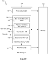
- Figure 1 shows a ray tracing system 100 comprising a ray tracing unit 102 and a memory 104.
- the ray tracing unit 102 comprises a processing module 106, an intersection testing module 108 and processing logic 110.
- the intersection testing module 108 comprises one or more box intersection testing units 112, one or more polygon intersection testing units 114, a ray rescaling unit 116 and an instance transform unit 118. It is noted that there may be more than one ray rescaling unit and/or more than one instance transform unit.
- the ray tracing unit 102 receives geometric data defining objects within the 3D scene.
- the ray tracing unit 102 also receives ray data defining rays that are to be tested for intersection.
- the rays may be primary rays or secondary rays.
- the processing module 106 is configured to generate an acceleration structure based on the geometric data, and to send the acceleration structure to the memory 104 for storage therein.
- the intersection testing module 108 can retrieve nodes (e.g. comprising data defining axis-aligned boxes corresponding to the nodes) of the acceleration structure from the memory 104 to perform intersection testing of rays against the retrieved nodes. To avoid reading in the whole acceleration structure at a time, the intersection testing module 108 retrieves a subset of the boxes from one level of the acceleration structure from memory 104 at each stage, based on the results of previous intersection tests.
- the box intersection testing unit(s) 112 perform intersection tests to determine whether or not a ray intersects each of the bounding boxes corresponding to nodes of the acceleration structure (where a miss can cull vast swathes of the hierarchical acceleration structure). If it is determined that a leaf node is intersected then the polygon intersection testing unit(s) 114 perform one or more polygon intersection tests to determine which object(s) (if any) the ray intersects.
- the convex polygons are triangles, although it is noted that in other examples, the convex polygons could be other shapes such as squares, rectangles, pentagons, hexagons, etc., so long as they are planar.
- the results of the intersection tests indicate which object in the scene a ray intersects, and the results may also indicate a position on the object at which the ray intersects the object (e.g. Barycentric coordinates), may also indicate a distance along the ray that the intersection occurs, and may also indicate the perceived orientation of the object from the ray's point of view (e.g., clockwise/anticlockwise or front/back facing).
- the intersection determination may be based on whether the distance along the ray that the intersection occurs is between the minimum and maximum clipping distances for the ray (t min and t max ).
- the intersection determination may be based on the perceived orientation of the object (e.g., for back-face culling).
- the results of the intersection testing are provided to the processing logic 110.
- the processing logic 110 is configured to process the results of the intersection testing to determine rendered values representing the image of the 3D scene.
- the rendered values determined by the processing logic 110 can be passed back to the memory 104 for storage therein to represent the image of the 3D scene.
- the ray tracing system uses an acceleration structure in order to reduce the number of intersection tests that need to be performed for a ray against convex polygons.
- an acceleration structure in order to reduce the number of intersection tests that need to be performed for a ray against convex polygons.
- some other examples might not use an acceleration structure, and may simply tests rays against the convex polygons without first attempting to reduce the number of intersection tests that need to be performed using an acceleration structure.
- the ray when performing intersection testing of a ray with a convex polygon, the ray is defined in terms of components in a space-coordinate system in which the convex polygon is defined.
- a ray-coordinate system is derived relative to the ray itself, and the convex polygon can be mapped onto the ray coordinate system.
- the term "space-coordinate system” is used herein to refer to the coordinate system in which the convex polygon is defined.
- the "space-coordinate system” may be a world space-coordinate system or an instance space-coordinate system.
- the space-coordinate system is a three-dimensional coordinate system
- a convex polygon is a region of three-dimensional space contained entirely within a plane, bounded by n ⁇ 3 line segments, such that all interior angles are less than or equal to 180°.
- a strictly convex polygon is a convex polygon such that all interior angles are strictly less than 180°.
- ray-coordinate system is used herein to refer to a coordinate system that is specific to a ray, and which has its origin at the origin of the ray. It is noted that in the examples described in detail herein the origin of the ray-coordinate system is the origin of the ray, but in other examples, any point along the ray's line could be used as the origin of the ray-coordinate system, with a suitable adjustment to the minimum and maximum clipping distances for the ray (t min and t max ).
- the ray-coordinate system has three basis vectors. A first of the basis vectors is aligned with the ray direction. A second and third of the basis vectors are both orthogonal to the first basis vector, and are not parallel with each other.
- the second and third basis vectors of the ray-coordinate system are not, in general, orthogonal to each other, although in some examples it is possible that they are orthogonal to each other. Furthermore, in examples described herein, the second and third basis vectors of the ray-coordinate system have a 0 as one component when expressed in the space-coordinate system. In some examples, the second and third of the basis vectors of the ray-coordinate system have a value of ⁇ 1 (i.e. a magnitude of 1) for one component when expressed in the space-coordinate system.
- the vertices defining the convex polygon are translated for use in performing the intersection testing using the ray-coordinate system by subtracting the ray origin from the positions of the vertices defining the convex polygon. Subtracting the ray origin from the positions of the vertices defining the convex polygon means that the position of the polygon is then defined relative to the origin of the ray. By shifting the vertices by the ray origin first, all relative error in downstream calculations is centred around the ray origin. Assuming that the same is true for the box tester, this makes guaranteeing conservatism (i.e., no false negatives) easier.
- Figure 2 illustrates a ray 202 and two convex polygons 204 and 206.
- the two polygons are triangles and they share an edge such that they form a quad.
- the orientations of the two polygons are indicated as clockwise, as viewed and from the ray's perspective, in Figure 2 .
- Polygon 204 is defined by the ordered set of vertices ( v 0 ,v 1 ,v 2 )
- polygon 206 is defined by the ordered set of vertices ( v 1 , v 3 , v 2 ).
- the edge between vertices v 1 and v 2 is shared by polygons 204 and 206.
- the two polygons are said to be specified with consistent winding.
- the x, y and z basis vectors of the space-coordinate system are shown in Figure 2 .
- the space-coordinate system could be a world space coordinate system of a scene being rendered, or the space-coordinate system could be the instance space-coordinate system of an instanced set of geometry within a scene being rendered.
- the origin of the ray-coordinate system that is used in the intersection testing is the origin of the ray.
- the positions of the vertices defining the polygons 204 and 206 are translated by subtracting the ray origin from the positions of the vertices. In the example shown in Figure 2 , the ray 202 intersects the polygon 204 at an intersection point 208.
- the x, y and z components of the ray and the vertices defining the polygons are selectively permuted, such that
- the selective permutation of the axes is performed such that D z will be the major component of the ray direction.
- Figure 2 shows the ray 202 and polygons 204 and 206 in relation to the basis vectors after the translation and the selective permutation of the axes of the ray and polygons have been performed, such that the origin of the ray is at the origin of the coordinate system, and such that
- the basis vectors of the ray-coordinate system are represented as P , Q and S in Figure 2 .
- P and Q are not necessarily orthogonal to each other. For example, unless D x or D y is zero then P and Q will not be orthogonal to each other.
- D z cannot be zero because of the selective permutation of the axes such that D z is the major component of the ray direction and because a valid ray direction vector must have a non-zero magnitude in order to define a line.
- the values of D x D z and D y D z are always well-defined and have a magnitude in the range from zero to one inclusive, and the values of D z D x and D z D y have a magnitude in the range from one to positive infinity (inclusive).
- the choice of the scalar values A, B and C can affect the handedness of the system.
- Each scalar value (from the scalar values A, B and C) that is negative flips the handedness of the system, e.g. from left-handed to right-handed. If an even number of the scalar values A, B and C are negative, then they cancel out and we return to a left-handed system.
- a sign of the mapping from the space-coordinate system to the ray-coordinate system may affect the perceived primitive orientation (given a fixed primitive winding). For example, a negative sign of the mapping may reverse primitive orientation and a positive sign of the mapping may preserve primitive orientation.
- the sign of the mapping may be given as: sgn D z XOR sgn A XOR sgn B XOR sgn C XOR sgn ⁇ wherein sgn( ⁇ ) indicates whether the permutation reverses the mapping sign.
- sgn(A), sgn(B) and sgn(C) come from rescaling the above ray-coordinate system bases.
- the value of the sign of the permutation sigma, ⁇ comes from the way the ray components are reordered (i.e. "permuted" by sigma, ⁇ ) to put the major component into a specific position (e.g. the final/z coordinate). By doing so, we leave two choices for which positions the minor coordinates go in. One of these choices corresponds to rotating all the coordinates, the other corresponds to transposing two of the coordinates.
- D x or D y may be zero. Therefore, in these examples, care needs to be taken when handling the values of ⁇ D z D x and ⁇ D z D y .
- the values of D x or D y may be perturbed by some small amount so that they are never exactly zero. For example, values of zero can be replaced with non-zero values that are small enough to behave like zero in the operations described herein.
- D x or D y may be zero. Therefore, in these examples, care needs to be taken when handling the values of ⁇ 1 D x and ⁇ 1 D y .
- the values of D x or D y may be perturbed by some small amount so that they are never exactly zero. For example, values of zero can be replaced with non-zero values that are small enough to behave like zero in the operations described herein.
- the example basis vectors given in the second, third, fourth and fifth examples described above all have consistent handedness, whereas the handedness of the basis vectors given in the sixth and seventh examples described above may either have consistent or opposite handedness, depending on the signs of D x and D y .
- , 0, ⁇ sgn( D z ) D x ) , i.e. either P (+
- ,0,-sgn( D z ) D x ) or P (-
- , ⁇ sgn( D z ) D y ), i.e. either Q (0,+
- ,-sgn( D z ) D y ) or Q (0,-
- ), i.e. either P (+sgn( D x ) D z , 0,-
- ) or P (- sgn ( D x ) D z , 0,+
- ), i.e. either Q (0 , +sgn( D y ) D z ,-
- ) or Q (0,-sgn( D y ) D z ,+
- each reciprocal may be evaluated to some accuracy (usually less accurate than comparable floating point operations) and then those evaluated values may be treated as if they were exact, in essence perturbing the direction of the ray direction for the sake of improving the accuracy of all intersection testers (improving consistency across the board).
- Another advantage of using a reciprocal basis is that it provides more flexibility in how the intersection distance, if required, is calculated.
- intersection parameter t may be alternatively computed as 1 D x p x , 1 D y p y or 1 D z p z .
- This may provide superior error characteristics if, for example, the component is selected corresponding to the axis for which a given convex polygon's components have the smallest range. This is in contrast with a non-reciprocal basis for which it is less cost effective to perform a calculation involving the reciprocals 1 D x and 1 D y without additional per ray storage.
- Table 1 below shows eight examples (denoted A to H) of different ray formats and basis vectors (up to sign) which may be used in different examples.
- the phrase "up to sign" here means that P and Q can be scaled by any unit value, i.e. restricted to the set ⁇ -1. +1 ⁇ .
- Table 1 also shows the number of multiply and reciprocal operations that would be performed per ray for the different ray formats, the number of multiply operations that would be performed per vertex for the projection into 2D ray space with its corresponding basis, and the reciprocal and multiply operations that would be performed per primitive for the intersection distance calculation.
- the different options for the ray formats and basis vectors can be compared with each other based on the total cost of all the floating point operations (FLOPs) from both the ray format encoding, the basis projection and the distance calculation.
- FLOPs floating point operations
- Options B, D, F and H are generally all improvements over A, C, E and G respectively, as they shift the reciprocal from the (per primitive) distance calculation to the (per ray) ray format encoding.
- Option B (and option A) is the default ray format/basis which is the most intuitive way to perform the intersection testing but is not the most efficient in terms of the number of floating point operations that need to be performed.
- Option F (and option E) reduces the number of multiply operations that are performed per vertex in the basis projection by two relative to option B (and option A).
- Options C, D, G and H use reciprocal bases.
- Option D (and option C) reduces the number of multiply operations that are performed per vertex in the basis projection by one, and reduces the number of multiply operations that are performed per primitive in the distance calculation by one, relative to option B (and option A).
- Option H reduces the number of multiply operations that are performed per vertex in the basis projection by two relative to option B (and option A).
- a basis vector has a 0 as a component value then a multiply and/or add operation (e.g. as used for performing a dot product or a cross product) involving that basis vector will not include a multiply and/or an add operation for the component which is 0, thereby reducing the number and/or complexity of operations that need to be performed.
- a multiply and/or add operation e.g. as used for performing a dot product or a cross product
- the intersection testing module 108 is implemented in fixed function circuitry then reducing the number and/or complexity of operations that are performed will tend to reduce the size (i.e. the silicon area) of the intersection testing module 108.
- the fixed function circuitry may comprise one or more multiply-and-add components (e.g.
- a fused singly rounded multiply-add unit for performing multiplications and additions using the second and third basis vectors of the ray-coordinate system.
- a singly rounded floating point implementation i.e. rounding is applied to the exact final result to ensure a representable value is output
- this is more accurate and typically smaller in area than a sum of products, multiply rounded (both products and sum). Its area may even be comparable to a less accurate multiply rounded implementation, which is less likely to be the case for more complex operations.
- Floating point add and multiply operations are not associative. Reducing the operations, which reduces the possible orderings, thus may have other benefits in terms of consistency of results.
- n basis vectors of the ray coordinate system can be defined where a first of the basis vectors of the ray coordinate system is aligned with the ray direction, and there are (n-1) other basis vectors which are orthogonal to the first basis vector. If n>2 then no pairing of the (n-1) other basis vectors are parallel. Furthermore, the (n-1) other basis vectors have zeros for (n-2) components when expressed in the space-coordinate system.
- the n basis vectors of the ray coordinate system form a basis of n-dimensional space (they are linearly independent and hence spanning).
- P B ( D z , 0, 0, -D w )
- Q C (0 ,D z , 0 ,-D x )
- R D (0,0, D z ,-D y )
- the selective permutation of the axes ensures that D z is the major component of the ray direction vector, i.e.
- A, B, C and D are nonzero scalars, and they may be chosen to make one of the coefficients unital, e.g. as described above in relation to the three dimensional examples.
- the four dimensions may correspond to three spatial dimensions and one temporal dimension.
- an expression for the sign of the determinant (similar to expression (1) given above for the 3D case) may be given as: sgn A XOR sgn B XOR sgn C XOR sgn D XOR sgn ⁇
- the permutation sigma may reverse the mapping sign if the major component of the ray direction vector is the W or the Y axis, but not if the major component of the ray direction vector is the X or the Z axis.
- permuting the components so that the major component is in the final position may involve a four cycle for a major axis of Wand a transposition for a major axis of Y, in both cases flipping the sign.
- the ray and the convex polygon are transformed from the space-coordinate system into the ray-coordinate system, wherein the intersection testing is performed in the ray-coordinate system.
- Testing in the ray-coordinate system could be performed by determining if the ray intersects with the convex polygon defined by its vertices as defined in the ray-coordinate system.
- a full transformation of the ray and the convex polygon into the ray-coordinate system does not need to be performed.
- the axes are selectively permuted to ensure that D z is the major component of the ray direction vector. Furthermore, the axes may be selectively reversed (or "reflected") to ensure that all of the components of the ray direction vector are non-negative, i.e. D z > 0, D x ⁇ 0 and D y ⁇ 0.
- the selective reversing of the axes causes the ray direction vector to point into the octant of the space-coordinate system which has positive values for x, y and z .
- D z is the major component of the ray direction vector this means that D x D z and D y D z are in a range from 0 to 1 and it means that D z D x and D z D y are in an interval from 1 to positive infinity.
- a mapping indication of the sign of the change-of-basis mapping can be stored, wherein the mapping indication indicates whether the mapping from the space-coordinate system to the ray-coordinate system affects the perceived polygon orientation.
- the mapping indication can be used during intersection testing of the ray with a polygon to ensure the correct orientation (perceived by the ray in the original space-coordinate system) is output.
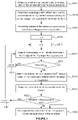
- Figure 3 is a flow chart for a method of performing intersection testing for a ray with respect to a plurality of convex polygons (e.g. triangles), performed by the polygon intersection testing unit(s) 114 of the intersection testing module 108.
- the ray Prior to the intersection testing of the ray with respect to the polygons performed by the polygon intersection testing unit(s) 114, the ray may be tested by the box intersection testing unit(s) for intersection, with boxes representing nodes of an acceleration structure, wherein the ray is scheduled for intersection with a polygon if the ray is determined to intersect a leaf node of the acceleration structure which references the polygon.
- step S302 data defining the ray 202 and data for the vertices defining the convex polygons 204 and 206 are obtained at the intersection testing module 108.
- data defining the components of the ray origin and the ray direction in the space-coordinate system are obtained.
- the data defining the ray origin may be the three components of the ray origin position in the space-coordinate system, O x , O y and O z .
- the data defining the ray direction comprises the three components of the ray direction in the space-coordinate system, D x , D y and D z .
- some different values defining the ray direction may have been pre-computed and stored in a store, such that in step S302 the pre-computed values may be read.
- three values may be read to define the ray direction data, and these three values may be D x D z , D y D z and 1 D z .
- different pre-computed values may be read to define the ray direction, e.g. values of D z D x , D z D y and D z may be read.
- values of D z D x , D z D y and 1 D z may be read.
- values of 1 D x , , 1 D y and 1 D z may be read.
- other values may be pre-computed and read which can be used to define the ray direction.
- the roles of these three values are distinct, and they are not always all needed.
- a first and key purpose of a triangle tester is an intersection determination. This uses the first two values, e.g. either D x D z and D y D z or D z D x and D z D y or similar, possibly with some signs depending on the choice of B and C. These are used to generate P and Q against which the primitive vertices are projected.
- the barycentric coordinates of an intersection point can be derived from the intersection determination without additional input.
- an intersection distance calculation may use any of 1 D x , 1 D y or 1 D z in conjunction with the corresponding component of the intersection point to determine the intersection distance.
- step S302 data defining the x, y and z components of the positions of the vertices defining the convex polygons 204 and 206 is read in step S302.
- the permutation may comprise a rotation of the three axes such that the x components become the z components, the z components become the y components, and the y components become the x components; and if the original y component of the ray direction vector has a larger magnitude than the original x and z components of the ray direction vector then the permutation comprises a transposition of the y and z axes such that the y components become the z components, and the z components become the y components (and the x components stay as the x components).
- step S304 the selective reversing of zero, one or more of the axes is performed so that the ray direction is into the octant with positive x, y and z.
- the "reversing" of the axes may be referred to as “reflecting", “inverting” or “negating”, and may involve changing the sign of all of the component values in the dimension along the axis in question.
- the data defining the ray comprises the ray origin and the ray direction, and the data defining the convex polygon comprises three or more vertex positions. It is noted that reversing an odd number of the axes reverses the perceived orientation of the polygons.
- step S306 the intersection testing module 108 projects the vertices of the convex polygons onto a pair of axes orthogonal to the ray direction, wherein the origin of the pair of axes corresponds with the ray origin.
- This projection of the vertices of the convex polygons onto a pair of axes orthogonal to the ray direction may comprise transforming the vertices of the convex polygons into the ray coordinate system described above.
- step S306 may involve subtracting the respective components of the ray origin ( O x , O y and O z ) from respective components of the data defining the positions of the vertices defining the polygons, to thereby determine components of the positions of the vertices defining the polygons relative to the ray origin.
- the ray-coordinate system has three basis vectors, wherein a first of the basis vectors is aligned with the ray direction; and wherein a second and a third of the basis vectors are respectively aligned with said pair of axes orthogonal to the ray direction, wherein the second and third basis vectors: (i) are not parallel with each other, and (ii) have a 0 as one component when expressed in the space-coordinate system.
- the second and third basis vectors may have ⁇ 1 as one component when expressed in the space-coordinate system.
- the projection can take the form of a dot product.
- This may be implemented by separate multiplications and an addition, or alternatively as a (singly rounded) fused DP2 (2D dot product), which in this latter case would ensure that the computed components have finite relative error with the properties discussed earlier.
- a mapping indication is stored to indicate whether mapping from the space-coordinate system to the ray-coordinate system (i.e. steps S304 and S306) has altered the perceived orientation of the polygons. If the perceived orientation of the polygons has changed then this is taken into account in the intersection process, e.g. in step S318, in order to ensure that the mapping from the space-coordinate system to the ray-coordinate system in steps S304 and S306 does not prevent the intersection testing module from correctly determining whether a ray intersects a polygon.
- Figure 6 illustrates the two polygons 204 and 206 shown in Figure 2 when they have been projected onto the pair of axes aligned with the basis vectors P and Q (i.e. the second and third basis vectors of the ray coordinate system).
- the ray is at the origin and directed into the page, i.e. the components of the ray direction vector along the P and Q axes are zero. Therefore, the intersection position 208 representing the intersection of the ray with the polygon 204 is at the origin in Figure 6 .
- Figure six indicates that the orientations of the two polygons 204 and 206 both appear as clockwise in Figure 2 , as determined by the winding order of the vertices in the ordered sets of vertices defining the polygons.
- a parameter, k is set to zero.
- the parameter, k is used to indicate a particular convex polygon.
- a parameter, e is set to zero.
- the parameter, e is used to indicate a particular edge of a convex polygon.
- the polygon's winding order i.e., the order of its vertices
- the maximum value (e max ) for the parameter, e is 2.
- the parameter, e can take values of 0, 1 or 2 to indicate the three edges of a triangle.
- the maximum value (e max ) for the parameter, e is n - 1.
- Each edge of a convex polygon is defined by two of the projected vertices as an ordered pair, indicating the direction of the edge.
- polygon 204 shown in Figure 6 has a first edge defined by the projected vertices v 0 and v 1 , i.e., directed from v 0 to v 1 , a second edge defined by the projected vertices v 1 and v 2 , i.e., directed from v 1 to v 2 ,, and a third edge defined by the projected vertices v 2 and v 0 , i.e., directed from v 2 to v 0 .
- other functions of the positions of the two projected vertices defining the edge may be used to determine the parameter w.
- the parameter w is determined using the 2D cross product in different ways in different implementations. Two examples are described in detail below with reference to Figures 4 and 5 respectively.
- the two projected vertices v i and v j may be provided to the 2D cross product, f ( v i ,v j ), in the order given by the directed edge, which is inherited from the ordered set of vertices defining the convex polygon (i.e., its winding order).
- step S318 the polygon intersection testing unit(s) 114 of the intersection testing module 108 determines whether the ray intersects the k th polygon based on the w parameters determined for the edges of that polygon. For example, the determination as to whether the ray intersects the k th polygon may be based on the signs of the w parameters determined for the edges of the k th polygon.
- the w parameters determined for the edges of the k th polygon all have the same sign then it is determined that the ray intersects the k th polygon; whereas if it is not the case that the w parameters determined for the edges of the k th polygon all have the same sign then it is determined that the ray does not intersect the convex polygon.
- step S318 comprises using the parameters determined for the edges of the convex polygon to determine whether the ray passes on the inside of the edges of the convex polygon, wherein it is determined that the ray intersects the convex polygon if it is determined that the ray passes on the inside of all of the edges of the convex polygon, and wherein it is determined that the ray does not intersect the convex polygon if it is determined that the ray passes on the outside of one or more of the edges of the convex polygon.
- step S314 could be modified to also identify, after we have processed at least 2 edges, if we have one or more determined w parameters that are strictly positive and one or more w parameters that are strictly negative for edges of a polygon, and in that case the polygon may be marked as a "miss" without determining w parameters for any remaining edges of the polygon.
- the signs of w might need to match some predetermined value (e.g., when back-face culling), and if they do not match the predetermined value then the polygon can be discarded.
- some predetermined value e.g., when back-face culling
- the signs of w might need to match some predetermined value (e.g., when back-face culling), and if they do not match the predetermined value then the polygon can be discarded.
- some predetermined value e.g., when back-face culling
- front/back-facing primitives e.g., back-face culling
- edges may be shared (perhaps with reversed directions) within a single batch of convex polygons, and in this situation each unique edge may be tested once and the results for a shared edge can be duplicated (perhaps with reversed sign) across both polygons sharing the edge.
- the presence of one or more w parameters with zero magnitude may be treated as a special case. For example, if the w parameters for all of the edges of the polygon have non-zero magnitude, it may be determined that the ray intersects the k th polygon only if all edges have matching signs for their w parameters (similar to as described above), but if, one or more w parameters have zero magnitude then an intersection is determined only if all of the zero magnitude w parameters (for edges of nonzero projected length) have a particular sign (e.g. a positive sign, or in other examples, a negative sign) and if all remaining edges with nonzero w parameters have mutually consistent sign.
- a particular sign e.g. a positive sign, or in other examples, a negative sign
- the signs of the one or more w parameters which have zero magnitude do not necessarily have to match the signs of the one or more w parameters which have non-zero magnitude to determine that the ray intersects the polygon.
- the determination of whether the ray intersects the convex polygon comprises: (i) determining that the signed parameter, w , for any edge of the convex polygon which has zero magnitude has a particular sign (e.g. positive in some examples, and negative in other examples), and (ii) determining that the signed parameters, w , for edges of the convex polygon which have non-zero magnitude have signs that are consistent with each other (albeit not necessarily consistent with the signs of the w parameters which have zero magnitude).
- n w parameters it is not necessary to determine all n w parameters once any pair of edges with nonzero w parameters is determined to have conflicting signs or, in some examples, once a w parameter is determined to have zero magnitude. In this latter case, it may be determined that intersection does not occur if the w parameter (for an edge of nonzero projected length) does not have the necessary sign.
- intersection does occur if precisely two w parameters (for edges of nonzero projected length) both have the necessary sign (guaranteeing sign consistency of the remaining edges with nonzero w parameters), since the magnitudes of at most two w parameters (for edges of nonzero projected length) may be zero (one zero w parameter indicates edge intersection and two zero w parameters indicate vertex intersection).
- a pair of equal signs of zero parameters for edges of nonzero projected length
- a pair of equal signs of zero parameters likewise determines an intersection, but this property often may not be exploited as edges with zero w parameters are generally not distinguished in this intersection test. This latter case assumes culling has not been enabled, as this may require checking the sign of one of the edges with nonzero w parameters.
- a negative nonzero value for the 2D cross product for an edge indicates that the ray may pass on the inside of the convex polygon, as the ray passes on the right of the edge, from the (directed) edge's perspective
- a positive non-zero value for the 2D cross product for an edge indicates that the ray does pass on the outside of the convex polygon, as the ray passes on the left of the edge, from the (directed) edge's perspective.
- a negative non-zero value for the 2D cross product for an edge indicates that the ray does pass on the outside of the convex polygon, as the ray passes on the right of the edge, from the (directed) edge's perspective
- a positive non-zero value for the 2D cross product for an edge indicates that the ray may pass on the inside of the convex polygon, as the ray passes on the left of the edge, from the (directed) edge's perspective.
- a zero value for the 2D cross product for an edge indicates that ray intersects exactly with the edge, i.e.
- Polygon 206 has a clockwise orientation as viewed given its winding, so the ray may pass on the inside of the convex polygon, as the ray passes on the right of the first edge of polygon 206 defined by vertices v 1 and v 3 .
- the w parameters, which are based on the 2D cross products, for the first and second edges of polygon 206 are negative, whilst the w parameter, which is based on the 2D cross product, for the third edge of polygon 206 is positive. Therefore, the ray is determined to not intersect the polygon 206, nor can a consistent orientation be established. It can be seen that the intersection point 208 is outside the polygon 206. It is noted that for a valid convex polygon, it is not possible for the ray to pass on the outside of all the edges of the polygon (e.g.
- step S320 the polygon testing unit(s) 114 of the intersection testing module 108 outputs an indication of the result of the determination of whether the ray intersects the k th polygon.
- This indication could be a binary indication (e.g. a one-bit flag) to indicate either a 'hit' or a 'miss' of the ray in respect of the polygon. In other examples, the indications could have different forms.
- additional output attributes e.g., barycentric coordinates, orientation (clockwise/anticlockwise or front/back facing), and/or an intersection distance.
- step S322 the polygon testing unit(s) 114 of the intersection testing module 108 determines whether there are more polygons to test. If so, then the method passes to step S324 in which the parameter, k, is incremented, and then the method passes back to step S310 so that steps S310 to S320 can be performed for the next polygon in order to determine whether the ray intersects the next polygon. When there are no more polygons to test, the method passes to step S326. Step S326 can be performed before, after or during step S322, i.e. step S326 can be performed following step S320 irrespective of whether there are more polygons to test.
- the outputted indication is used in the ray tracing system 100 (e.g. by the processing logic 110) for rendering an image of a 3D scene.
- the polygon intersection testing unit(s) 114 of the intersection testing module 108 can output an intersection distance (i.e. a distance between the ray origin and the point at which the ray intersects the polygon), and an indication of the position on the polygon at which the ray intersects it (e.g. defined in barycentric coordinates), and this information can be output to the processing logic 110.
- step S326 all the intersection tester output attributes, alongside other external attributes, e.g., scene data (e.g., light source(s), cube map), instance data, primitive/polygon ID, vertex data (e.g., positions, normal, texture coordinates), texture address(es), secondary ray data, etc., are processed to determine a colour value and/or generate additional secondary rays for future traversal.
- scene data e.g., light source(s), cube map
- instance data e.g., primitive/polygon ID
- vertex data e.g., positions, normal, texture coordinates
- texture address(es) e.g., secondary ray data, etc.
- the magnitudes of the w parameters for the different edges of a polygon that the ray is determined to intersect may be used for determining the barycentric coordinates.
- the polygon is a triangular polygon having vertices v 0 , v 1 and v 2
- the w values give twice the signed area of the sub-triangles formed by vertices ( v, v 0 , v 1 ), ( v, v 1 , v 2 ) and ( v, v 2 , v 0 ) , up to uniform nonzero rescaling from the ray-space projection.
- intersection distances are output in step S320, these may be calculated in terms of ray lengths rather than actual Euclidean distances.
- the length of the ray may be divided through by D x 2 + D y 2 + D z 2 , and the intersection distance can be determined in terms of ray-lengths from the ray origin.
- the barycentric interpolated coordinates are then divided by A D x 2 + D y 2 + D z 2 to obtain ⁇ .
- the 1 D z is required to prevent the intersection distance being overcounted by a factor of D z and motivates the storage of this quantity in the ray format.
- 1 D z or 1 D z has been pre-computed and stored, it is often most efficient to select the last of these three options so that the intersection distance can be calculated by multiplying the barycentric interpolated vertex z components by the pre-computed reciprocal.
- the projection operations involve terms of v x D x , v y D y and v z D z (which may be thought of as mapping the coordinates to "t" space) or possibly, as in rescaled examples, terms involving D z v x D x , D z v y D y and ⁇ z (rescaled t space).
- the barycentric interpolated result may be scaled by the appropriate one of 1 D x , 1 D y and 1 D z (which may again involve a further scaling by 1 D z if D z D x , D z D y and 1 D z have been pre-computed and stored).
- both scaled and unscaled reciprocal bases provide the flexibility to select which axis should be used for interpolation, which as mentioned earlier, allows an axis to be chosen that has the most attractive error properties for a given convex polygon (e.g. by selecting the axis with the minimum range of values across the convex polygon).
- the data defining the ray and the data for the vertices defining the polygon is read in step S302, and then in step S304 the x, y and z components of the ray and the vertices defining the polygon are selectively permuted and/or reversed so that D z ⁇ D x ⁇ 0 and D z ⁇ D y ⁇ 0.
- the ordering of parts of these two steps may be different in different examples.
- the selective permutation and/or reversing of the x, y and z components of the ray may be performed before the data is obtained.
- the pre-computed ray direction data that is read by the intersection testing module could comprise values of D x D z , D y D z and D z or 1 D z , values of D z D x , D z D y and D z or 1 D z , or values of 1 D x , 1 D y and D z or 1 D z to give just some examples, and in other examples, other values may be pre-computed and read in order to define the ray direction.
- an indication of the major axis (e.g., a 2-bit enumeration), indicating the permutation, as well as the original signs of the ray direction components, indicating the reversal, is stored so that the same pre-computation can be applied to the polygon vertices when the ray is to be tested against them (and to post-modify the orientation determination if appropriate).
- the (only) overhead here is an extra 2 bits for indicating the major axis, but this (negligible) amount of additional storage is outweighed by avoiding finding the major component of the ray direction every time a polygon is tested against the ray.
- an issue can arise in the intersection testing process if the ray intersects a point on an edge of a polygon. For example, if the ray intersects a point on a shared edge, or if the ray intersects a shared vertex of a closed fan, which is shared by multiple polygons, then, in order for the intersection testing process to be "watertight", the polygon intersection testing unit(s) 114 should, in most cases, determine that the ray intersects at least one of the polygons. In order for the intersection testing process to be "non-redundantly watertight", the polygon intersection testing unit(s) 114 should, in most cases, determine that the ray intersects one and only one of the polygons.
- intersection testing process is not watertight then rendering errors may be introduced into the rendered images, such as cracks in geometry, which is not desirable.
- One way to achieve a "watertight" intersection test is to project onto a ray-dependent plane (e.g., given by ray-space basis vectors P and Q), followed by exact determination of whether the polygon, including its boundary, cover the origin (e.g., by establishing whether the origin is inside of, or strictly on, each edge).
- a plane vertex ordering scheme is used to ensure that the intersection tests are "non-redundantly watertight".
- the "plane vertex ordering scheme” may be referred to herein simply as a "vertex ordering scheme”.
- the plane vertex ordering scheme defines a universal ordering of the 2D projected vertices which is independent of the winding order of the vertices (i.e., inherited from the ordered sets of vertices defining the convex polygons).
- the ordering of the projected vertices according to the plane vertex ordering scheme is a total strict ordering. This implies that, for two distinct projected vertices a and b, we either have a ⁇ b or a > b.
- the ordering of the projected vertices according to the plane vertex ordering scheme defines a direction of each edge, independent of the direction inherited from the winding order(s) of the polygon(s) which include the edge.
- the universal direction of a projected edge is from its vertex with smallest p component to its vertex with largest p component, unless the projected vertices of the edge have equal p components, in which case the direction of a projected edge is from its vertex with smallest q component to its vertex with largest q component.
- any nondegenerate projected convex polygon i.e., with a nonzero projected area
- v i ⁇ v j or v j ⁇ v i for all such edges, according to the plane vertex ordering scheme, and hence a well-defined direction for all such edges.
- v i ⁇ v j or v j ⁇ v i for all such edges, according to the plane vertex ordering scheme, and hence a well-defined direction for all such edges.
- v i ⁇ v j or v j ⁇ v i for all such edges, according to the plane vertex ordering scheme, and hence a well-defined direction for all such edges.
- edge is degenerate (i.e., equal components along the axis parallel with the ray direction), or that the edge is nondegenerate (i.e. with different components along the axis parallel with the ray direction vector) and the ray is looking along the edge of the convex polygon, i.e., its direction is perpendicular to the normal of the (planar) polygon (up to the accuracy of the projection).
- the former case must not occur for three or more edges of the convex polygon.
- the plane vertex ordering scheme has eight alternative characterisations giving eight alternative pairs (for clockwise and anticlockwise orientations) of edge tie-break behaviours.
- edge tie-break behaviours For convex polygons with a clockwise orientation the examples described herein exhibit a "Left-Top Rule", whereas for convex polygons with an anticlockwise orientation the examples described herein exhibit a "Right-Bottom Rule”.
- Other examples exhibit different tie-break behaviour pairs.
- the eight alternative tie-break behaviour pairs exhibited are:
- the above terms indicate which edges are considered part of the boundary of a convex polygon in intersection determination.
- the first/second tie-break behaviours correspond to when the convex polygon has an apparent clockwise/anticlockwise orientation viewed in projected 2D space.
- edge tie-break behaviour depends on the winding/orientation of the convex polygon, we call it a "winding/orientation dependent" watertightness scheme.
- the tie-break behaviour reverses for polygons having the opposite orientation, e.g., "Left-Top Rule” and "Right-Bottom Rule”.
- Left-Top Rule indicates that all edges bounding the convex polygon from above, or bounding the convex polygon from the left but precisely vertical, are considered part of the boundary of the polygon, and therefore are intersected.
- these edge tie-break behaviours apply to a single ray only, and may change from ray to ray, e.g., when there is a change of perceived orientation and/or major axis.
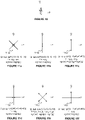
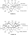
- Figure 7a indicates the orientations of the two polygons from the ray's perspective: both polygons 702 and 704 appear clockwise as viewed, which is inherited from their winding order.
- Figure 7a indicates the direction of the edges of polygon 702, according to the ordering of the vertices in the ordered set of vertices defining the polygon 702, with closed filled arrow heads.
- Figure 7a indicates the direction of the edges of polygon 704, according to the ordering of the vertices in the ordered set of vertices defining the polygon 704, with open arrow heads.
- Figure 7b indicates directions of the edges of the two polygons according to the plane vertex ordering scheme mentioned above, some of which differ from the directions of the edges given by the winding order in Figure 7a .
- the polygons sharing the edge have consistent edge winding, i.e. with the two convex polygons 702 and 704 sharing the edge 706 with endpoints ⁇ v 1 , v 2 ⁇ , they are ordered ( v 1 , v 2 ) in one polygon (e.g. polygon 702) but are reversely ordered ( v 2 , v 1 ) in the contiguous neighbouring polygon (e.g. polygon 704), inherited from the respective (consistent) winding orders of the vertices in the ordered sets of vertices defining the polygons.
- the examples described herein target manifold edges, i.e.
- the w parameter is determined based upon whether the ordering, defined by the vertex ordering scheme (i.e. the "plane vertex ordering scheme"), of the projected vertices defining the edge matches the ordering of the vertices in the ordered set of vertices defining the convex polygon (e.g. inherited from the winding order of the convex polygon).
- the vertex ordering scheme i.e. the "plane vertex ordering scheme”
- the sign of the w parameter for the edge of the polygon is determined based upon whether the edge direction inherited from the plane ordering of the projected vertices defining the edge, defined by the plane vertex ordering scheme, matches the edge direction inherited from the winding order of the vertices in the ordered set of vertices defining the convex polygon.
- the ray is determined to intersect a point on an edge if the 2D cross product of the projected positions of the two vertices defining the edge has a magnitude of (plus or minus) zero. If the ray intersects an edge (e.g.
- the plane direction of the edge is determined according to the plane vertex ordering scheme, and this direction may be referred to as the "universal plane direction of the edge" (e.g. as seen in Figure 7b ). It is then determined whether the edge has a matching winding direction inherited from the winding order of the polygon. If the polygons have consistent winding orders (e.g.
- the edge will have a different winding direction for each of the two polygons: one of the two polygons sharing the edge will have a winding direction matching the universal plane direction of the edge, whereas the other polygon will have a winding direction not matching the universal plane direction of the edge.
- the polygon intersection testing unit(s) 114 determines that the ray intersects with the polygon whose edge has a matching winding direction, and that the ray does not intersect with the polygon whose edge does not have a matching winding direction.
- the ray is determined to intersect polygon 702 in the example shown in Figures 7a and 7b .
- the winding direction of this edge in polygon 704 (which also appears as a clockwise orientation as viewed), inherited from the winding order of the vertices v 2 and v 1 in the ordered set of vertices ( v 1 , v 3 , v 2 ) defining the polygon 704, does not match the plane ordering of the projected vertices v 1 and v 2 according to the plane vertex ordering scheme. Therefore, the ray is determined to not intersect polygon 704 in the example shown in Figures 7a and 7b .
- the shared edge 706 it is determined to intersect one and only one of the polygons, 702, and thus "non-redundant watertightness" is ensured in this example.
- the particular implementation of the 2D cross product function f must be sign accurate when f ( v i ,v j ) ⁇ ⁇ 0.
- this property indicates that the sign of the implementation of f can be calculated only once for one polygon of a shared edge, and then the negated result can be used for the other polygon of the shared edge (assuming consistent winding). It is reasonable to expect an implementation of f to be sign accurate for f ⁇ ⁇ 0, as it is equivalent to correctly determining whether p i q j ⁇ q i p j (negative) or p i q j > q i p j (positive) for all p i q j ⁇ q i p j .
- the kernel of the implementation of the 2D cross product f must match the kernel of the 2D cross product f , i.e., the sets of input values (restricted to representable floating points) mapped to ⁇ 0 by each function must match.
- This can be achieved by using an implementation of f with fully expanded intermediates and one instance of RAZ (round away from zero) rounding on the result, or by using an extended range output.
- RAZ round away from zero
- the IEEE single precision floating point format allocates an encoding for both positive and negative zero (all zeros starting with a zero or one respectively).
- An implementation of the 2D cross product function f may generate -0 in place of +0, but this will be implementation specific.
- the precision of intermediate values may be expanded (be it implicitly or explicitly) to accommodate a larger range of values. It is clear that p i q j - q i p j can generate values outside the range of 8 bits of exponent and 23 bits of mantissa, given four 32-bit floats as input. Given this, some rounding is performed if the result is to be output in 32 bits.
- nonzero w matches the sign of 0 it is rounded to, then this is known as "sign accurate rounding".
- a nonzero w would be rounded to +0, it may instead be rounded to the minimal representable positive floating point value (e.g., when rounding away from zero), and where a nonzero w would be rounded to -0, it may instead be rounded to the maximal representable negative floating point value (e.g., when rounding away from zero).
- w is exactly 0 then one would normally expect it to be encoded as +0, but may sometimes (or always) be encoded as -0.
- the method described with reference to Figure 4 i.e., "edge direction on-edge check" does not require the 2D cross product function f to be consistent in the signs of exactly zero results, instead it overrides the sign in step S408.
- v 1 ⁇ v 2 according to the plane vertex ordering scheme.
- the edge 706 is defined by the ordered vertices v 2 and v 1 , i.e.
- step S312 comprises step S502 in which the polygon intersection testing unit(s) 114 of the intersection testing module 108 determines an implementation of the 2D cross product with sorted input vertices f (max( v i , v j ),min( v i , v j )) for the e th edge, defined by projected vertices v i and v j defining the k th polygon.
- the two projected vertices, v i and v j defining the edge are provided to the implementation of the 2D cross product function f in an order defined by the plane vertex ordering scheme.
- a binary function f is anti-commutative if swapping the order of the vertices reverses the sign of f .
- the "full edge sorting" method shown in Figure 5 lifts the restriction that the implementation of the 2D cross product function f be anti-commutative, whilst still ensuring that the w parameter is anti-commutative, and hence the result of this expression may be calculated only once for one polygon of a shared edge, and then the negated result may be used for the other polygon of the shared edge (assuming consistent winding).
- the implementation of f need only be sign accurate on the domain v i > v j and, further still, need not match the kernel of f , lifting additional restrictions over the "Edge check on-edge method". Although the implementation of f need not match the kernel of f , it must be consistent in sign, i.e. all positive or all negative, for values that f maps to zero.
- the edge 706 is defined by the ordered vertices v 1 and v 2 , i.e.
- the sign of the w parameter for edge 706 is different for polygons 702 and 704, such that the ray will be determined to intersect one (and only one) of the polygons 702 and 704, namely 702, thereby ensuring "non redundant watertightness" when the ray intersects the shared edge 706.
- Figures 8a and 8b the ray intersects a point on the end of an edge, in this case a vertex shared by multiple (e.g. five) polygons forming a closed fan.
- Figures 8a and 8b show a ray intersecting a vertex v 2 that is shared between five polygons 802, 804, 806, 808 and 810.
- Figure 8a indicates the winding orders of the five polygons, demonstrated by their clockwise orientation as viewed.
- Figure 8a indicates the direction of the edges of polygon 802, according to the ordering of the vertices in the ordered set of vertices defining the polygon 802, with closed filled arrow heads.
- Figure 8a indicates the direction of the edges of polygon 804, according to the ordering of the vertices in the ordered set of vertices defining the polygon 804, with open arrow heads.
- Figure 8a indicates the direction of the edges of polygon 806, according to the ordering of the vertices in the ordered set of vertices defining the polygon 806, with closed unfilled arrow heads.
- Figure 8a indicates the direction of the edges of polygon 808, according to the ordering of the vertices in the ordered set of vertices defining the polygon 808, with closed filled arrow heads.
- Figure 8a indicates the direction of the edges of polygon 810, according to the ordering of the vertices in the ordered set of vertices defining the polygon 810, with open arrow heads.
- Figure 8b indicates directions of the edges of the five polygons according to the plane vertex ordering scheme mentioned above.
- the polygon intersection testing unit(s) 114 of the intersection testing module 108 determines which of the polygons has two edges, both with the shared vertex as an endpoint, whose plane directions (according to the plane vertex ordering scheme) both match their winding directions (according to the winding order given by the ordered sets of vertices defining the polygon).
- the polygon intersection testing unit(s) 114 of the intersection testing module 108 determines which of the polygons has two edges, both with the shared vertex as an endpoint, whose plane directions (according to the plane vertex ordering scheme) both match their winding directions (according to the winding order given by the ordered sets of vertices defining the polygon).
- the polygon intersection testing unit(s) 114 of the intersection testing module 108 determines which of the polygons has two edges, both with the shared vertex as an endpoint, whose plane directions (according to the plane
- a vertex shared by such a closed fan of (non-overlapping) convex polygons is bounded (in the plane) by the endpoints of the edges meeting at the shared vertex .
- the polygons have consistent winding, there will exist one and only one polygon of the closed fan that has three ordered vertices according to its winding order, including the shared vertex as the middle vertex, whose ordering matches the ordering of the plane ordering scheme.
- the polygon directly below the shared vertex (or below and to the right in the case of a precisely vertical edge), e.g.
- the ray intersects the polygon 810, and that since the remaining nonzero w parameter is negative, the polygon 810 has a clockwise orientation as viewed.
- none of the other polygons 802 to 808 will have w parameters determined such that a pair of intersected edges both have negative sign (and zero magnitude) or, as an immediate corollary, that all edges have the same sign.
- ⁇ 21 , ⁇ 20 , ⁇ 10 , ⁇ 42 , ⁇ 41 , ⁇ 52 , ⁇ 54 , ⁇ 32 , ⁇ 53 and ⁇ 30 are all nonnegative values and, as all pairs of inputs to the implementation of the 2D cross product are in the kernel of f , the sign indicators ⁇ and ⁇ are consistent, i.e. they return either signs + and - respectively in all instances, or signs - and + respectively in all instances.
- polygon 810 is the one (and only one) polygon that is determined to be intersected by the ray for respective signs + and -
- polygon 804 is the one (and only one) polygon that is determined to be intersected by the ray for respective signs - and +, yielding three negative values for w in either case (also indicating a clockwise orientation as viewed).
- the sign of the w parameter for the e th edge is determined to be the same as the sign of f ( v i ,v j ) if it is determined that the ray should not intersect a point on the edge. Then the method passes to step S314.
- RTZ round towards zero
- the module comprising the lookup table and/or logic array is implemented on the intersection testing module 108 as a block of pre-configured logic in fixed-function hardware (e.g. as part of the polygon testing unit(s) 114).
- the functionality of the lookup table and/or logic array described herein can be considered to apply generally to the "module" comprising the lookup table and/or the logic array.
- the lookup table and/or logic array is configured to take, as its inputs, indications which classify each of the p i , q i , p j and q j coordinates as a trichotomy of negative, (plus or minus) zero or positive (e.g., as a "trit"), and to output, for valid combinations of classifications of the p i , q i , p j and q j coordinates, an indication of the sign of the signed parameter, w (e.g., as a bit).
- the lookup table or logic array may also be configured to take an indication of the sign of f and the boolean state of an "underflow flag" as two other input bits.
- the lookup table and/or logic array models a function with input trits p i , q i , p j and q j (possibly as well as input bit sgn( f ) and the boolean state of an underflow flag) to provide an output bit indicating the sign of w.
- the lookup table is reduced to a quarter of its size without the addition of the other two inputs.
- a "logic array” e.g. a configuration of logical operations in software or logical gates in hardware, performing the desired mapping.
- the symmetry of the problem, along with a small number of "don't care" outputs, allows the number of logic gates to be reduced.
- Some hybrid of the two implementations may also be possible, e.g. a reduced size LUT using some pre- or post- processing logic to leverage the symmetry of the problem. Either implementations may afford power or area gains over the other, depending on the specific architecture, where the first way (LUT implementation) may be more suitable to software, and the second (logic array implementation) may be more suitable to hardware in general.
- step S908 the polygon testing unit(s) 114 classify each of the p i , q i , p j and q j coordinates for the vertices v i and v j defining the e th edge as: (i) negative, (ii) (plus or minus) zero, or (iii) positive. It is noted that in order to be classified as negative or positive, a coordinate is non-zero. In other words, for the purposes of this classification of the coordinates, (plus or minus) zero is considered to be non-negative and non-positive. Where the coordinates are in a floating point format, and if denormals have been excluded or flushed, the exponent of a coordinate can be checked (e.g.
- indications of the classifications of the coordinates are input to the lookup table or logic array.
- the indications of the classifications can be considered to be used as indices or reference values to lookup a piece of data (i.e. the sign of w) from the lookup table or to determine the sign of w using the logic array.
- step S912 the polygon testing unit(s) 114 receives the output from the lookup table or logic array which indicates the sign of the w parameter for the edge. The method then passes to step S314 and continues as described above.
- lookup table or logic array makes the determination of the sign of the w parameter extremely fast to implement, so steps S908 to S912 can be performed with very low latency and very low power consumption.
- a small amount of pre-configured logic can be used to implement the lookup table or logic array so a small amount of silicon area may be used to implement the lookup table or logic array in hardware, but this area will be very small because the operations performed by the lookup table or logic array are simple to implement in hardware.
- This perturbation indicates that the position of the first of the projected vertices v i defining the edge would have coordinates ( p i + ⁇ p ) and ( q i + ⁇ q ) along the respective axes (P and Q) of the pair of axes of the coordinate system of a ray, and that the position of the second of the projected vertices v j defining the edge would have coordinates ( p j + ⁇ p ) and ( q j + ⁇ q ) along the respective axes (P and Q) of the pair of axes of the ray coordinate system.
- the perturbation being considered would be tiny, but it would be big enough (i.e., by being considered nonzero), and at such a steep angle no representable edge could share, to move the vertices of an edge passing through the origin so that the edge would no longer pass through the origin (such that the ray would no longer intersect the edge). Also, the perturbation being considered would be tiny enough (i.e., by being considered smaller than any representable vector) not to move the vertices of an edge not passing through the origin so that the edge would then pass through the origin (such that the ray would intersect the edge). Hence, with this consideration, it would not be possible for a ray to exactly intersect an edge (including its endpoints).
- the "endpoint sgn zero-check" method has eight alternative characterisations giving eight alternative edge tie-break behaviours.
- the examples described herein exhibit a "Right-Top Rule”.
- Other examples exhibit different tie-break behaviour pairs.
- the eight alternative tie-break behaviour pairs exhibited are:
- edges are considered part of the boundary of a convex polygon in intersection determination, regardless of the apparent orientation of the convex polygon viewed in projected 2D space.
- edge tie-break behaviour does not depend on the winding/orientation of the convex polygon, we call it a "winding/orientation independent" watertightness scheme.
- Left-Top Rule indicates that all edges bounding the convex polygon from above, or bounding the convex polygon from the left but precisely vertical, are considered part of the boundary of the polygon, and therefore are intersected.
- these edge tie-break behaviours apply to a single ray only, and may change from ray to ray, e.g., when there is a change of perceived orientation and/or major axis.
- the lookup table is configured to output, for all valid combinations of classifications of the p i , q i , p j and q j coordinates, an indication of the sign of the signed parameter w.
- the lookup table or logic array is configured to output: (i) for some valid combinations of classifications of the p i , q i , p j and q j coordinates, the sign of the signed parameter w as the sign, or opposite of the sign, of p i , q i , p j or q j , and (ii) for some invalid combinations of classifications of the p i , q i , p j and q j coordinates, the sign of the signed parameter w as any value.
- the lookup table or logic array is configured to further output: (iii) for some valid combinations of the classification of the p i , q i , p j and q j coordinates, the sign of the signed parameter w as the sign, or opposite of the sign, of the product of two of p i , q i , p j or q j , and (iv) for one or more other valid combinations of classifications of the p i , q i , p j and q j coordinates, the sign of the signed parameter w, as the sign of the implementation of the 2D cross product f .
- an "underflow flag" is used to determine which of (i), (ii), (iii) or (iv) is configured to be the output.
- the polygon intersection testing unit(s) 114 may operate according to a "round-away-from-zero" (RAZ) implementation type when determining the 2D cross product function for use in determining the w parameters, ensuring the kernel of the implementation of the 2D cross product matches the kernel of f .
- RAZ round-away-from-zero
- the lookup table may be configured to output, for all valid combinations of classifications of the p i , q i , p j and q j coordinates for which f can be determined to be zero, an indication of the sign of the signed parameter, w.
- Figures 11a to 11l illustrate possible situations in which a ray intersects an edge of a strictly convex polygon in a RAZ type, and also illustrate what the lookup table or logic array is configured to output as the sign of the w parameter for the different situations, as derived from the form of equation (2).
- Figures 11a to 11l illustrate the positions of the P and Q axes and (unperturbed) edges which intersect with the origin of the P and Q axes.
- Each edge is illustrated by a line connecting the vertices v i to v j which define the edge, with the arrowheads pointing in the direction from v i to v j , inherited from the winding order of a strictly convex polygon including that edge.
- the actual vertices v i and v j are not labelled in Figures 11a to 11l.
- the sign of the w parameter is set in this example to be equal to the sign of p i .
- the dual case i.e. the reverse case, to the situation shown in Figure 11a is shown in Figure 11i , for which the sign of the w parameter is set to be the opposite of the sign of p j .
- the dual case demonstrates the anticommutative property of the tie-break behaviour as switching the order of the input projected vertices, e.g. swapping every instance of i with j in the subscripts of p and q , negates the sign of the result.
- the situation shown in Figure 11c is its own dual case, i.e. its own reverse case, as the sign of q j is equal to the opposite of the sign of q i
- Figure 11d shows two types of edges which fall into this category, for the two possible signs of p i .
- the sign of the w parameter is set in this example to be the sign of p i .
- the dual case, i.e. the reverse case, to the situation shown in Figure 11d is shown in Figure 11h , for which the sign of the w parameter is set to be the opposite of the sign of p j .
- the sign of the w parameter is set in this example to be the sign of p i or the opposite of the sign of p j .
- the situation shown in Figure 11e is its own dual case, i.e. its own reverse case, as the sign of p i is equal to the opposite of the sign of p j .
- Figure 11g shows two types of edges which fall into this category, for the two valid combinations of signs of p i and p j .
- the situation shown in Figure 11g is its own dual case, i.e. its own reverse case, as the sign of p i is the opposite of the sign of p j .
- the sign of the w parameter is set in this example to be opposite to the sign of p j .
- the dual case, i.e. the reverse case, to the situation shown in Figure 11i is shown in Figure 11a , for which the sign of the w parameter is set to be the sign of p i .
- the sign of f is correct.
- the sign of the w parameter can be set to be equal to the sign of f in both alternative situations 11j and 12j (when an RTZ type implementation is used to calculate f , otherwise any value may be used for w).
- the lookup table or logic array may receive the sign of f as an input, and set the sign of the w parameter to be equal to the sign of f .
- the situation shown in Figure 11j is its own dual case, i.e., its own reverse case.
- Figures 11a to 111 illustrate all of the situations for combinations of inputs to the lookup table or logic array for situations in which an (possibly extended) edge can exactly intersect the origin of the P and Q axes. Therefore, when using an implementation of a RAZ type Figures 11a to 111 illustrate all of the situations in which the lookup table or logic array is used, and indicate the outputs of the lookup table or logic array for the different combinations of inputs.
- the polygon intersection testing unit(s) 114 may operate according to an implementation of the 2D cross product that is not a RAZ type for use in determining the w parameters.
- the implementation of the 2D cross product may use a rounding mode that is round to nearest, round towards zero, round towards positive infinity or round to negative infinity.
- the value of f may be determined to be (plus or minus) zero even though the exact value of f is not zero.
- a value of f that is very close to zero may be rounded to (plus or minus) zero. This loss of precision in calculations involving floating point numbers is referred to as "underflow".
- Figures 12a to 12j also show the position of the origin 1202, which does not appear perturbed, as shifting by ⁇ p and ⁇ q is negligible compared to the nonzero values of p i , q i , p j and q j in these underflow cases.
- Figure 12a shows four types of edges which fall into this category for the four possible combinations of signs of q i and p j .
- the sign of the w parameter is set in this example to be equal to the product of the signs of p i and q j .
- the dual case, i.e. the reverse case, to the situation shown in Figure 12b is shown in Figure 12a , for which the sign of the w parameter is set to be the opposite of the product of the signs of q i and p j .
- Figure 12c shows eight types of edges which fall into this category for the eight possible combinations of signs of q i , p j and q j .
- the sign of the w parameter is set in this example to be the opposite of the product of the signs of q i and p j .
- the dual case, i.e. the reverse case, to the situation shown in Figure 12c is shown in Figure 12e , for which the sign of the w parameter is set to be equal to the product of the signs of p i and q j .
- Figure 12d shows eight types of edges which fall into this category for the eight possible combinations of signs of p i , p j and q j .
- the sign of the w parameter is set in this example to be equal to the product of the signs of p i and q j .
- the dual case, i.e. the reverse case, to the situation shown in Figure 12d is shown in Figure 12f , for which the sign of the w parameter is set to be the opposite of the product of the signs of q i and p j .
- the sign of the w parameter is set in this example to be the opposite of the product of the signs of q i and p j .
- the dual case, i.e. the reverse case, to the situation shown in Figure 12f is shown in Figure 12d , for which the sign of the w parameter is set to be equal to the product of the signs of p i and q j .
- winding cannot be purely a function of input signs of the p i , q i , p j and q j coordinates.
- the implementation of the 2D cross product can flag up a case of underflow to detect this alternative situation 12g.
- This underflow flag can be passed as an additional input bit to the lookup table or logic array, to choose between the sign determination of the situation in Figure 11e , when the flag is not set, and the sign of the (sign accurate) determination of the 2D cross product for the situation in Figure 12g , when the flag is set.
- the situation shown in Figure 12h is similar to the situation shown in Figure 11e as neither of the coordinates of the first vertex v i are zero, i.e. p i ⁇ 0 and q i ⁇ 0, and neither of the coordinates of the second vertex v j are zero, i.e. p j ⁇ 0 and q j ⁇ 0. However, it differs from the situation shown in Figure 11e as the signs of p i and p j are opposite to each other, and the signs of q i and q j match each other.
- the sign of the w parameter is set in this example to be equal to the product of the signs of p i and q j , or the opposite of the product of the signs of q i and p j .
- the situation shown in Figure 12h is its own dual case, i.e. its own reverse case, as the sign of p i is opposite to the sign of p j , and the sign of q i matches the sign of q j .
- the situation shown in Figure 12i is similar to the situation shown in Figure 11e as neither of the coordinates of the first vertex v i are zero, i.e. p i ⁇ 0 and q i ⁇ 0, and neither of the coordinates of the second vertex v j are zero, i.e. p j ⁇ 0 and q j ⁇ 0. However, it differs from the situation shown in Figure 11e as the signs of p i and p j match each other, and the signs of q i and q j are opposite to each other.
- the sign of the w parameter is set in this example to be the opposite of the product of the signs of q i and p j , or the product of the signs of p i and q j .
- the situation shown in Figure 12i is its own dual case, i.e. its own reverse case, as the sign of q i is opposite to the sign of q j , and the sign of p i matches the sign of p j .
- the edge does not exactly pass through the origin, and instead the implementation of the 2D cross product f is determined to equal (plus or minus) zero only as the kernel of its implementation is a strict superset of its own kernel (e.g. due to underflow in the calculation).
- the potential problem with this situation is that the edge winding can be reversed without changing any of the input signs, e.g. by rotating the edge, e.g. by 180 degrees.
- winding cannot be purely a function of input signs of the p i , q i , p j and q j coordinates.
- we can detect the situations shown in Figures 12j and 11j by checking that the implementation of the 2D cross product f 0 and by checking that the input p t , q i , p j and q j coordinates have appropriate signs.
- the implementation of the 2D cross product function has "sign accurate rounding" off of the kernel of f meaning that, even in an underflow case, such as the situation shown in Figure 12j , the sign of the implementation of the 2D cross product matches the sign of f .
- the sign of the w parameter can be set to be equal to the sign of f .
- the lookup table or logic array may receive the sign of f as an input, and set the sign of the w parameter to be equal to the sign of f . Since the situations shown in Figures 11j and 12j are indistinguishable to the lookup table or logic array (i.e.
- edges can be detected simply by checking if the two projected endpoints are equal. Geometrically, a higher order polygon with such degenerate edges collapses to a lower order polygon (similar to a non-strictly convex polygon). Such pathological cases can be avoided by ensuring that no two vertices of a strictly convex polygon are equal. When the normal of the (planar) convex polygon is perpendicular to the ray direction it will also have zero area as it appears as a line, and hence will also be a degenerate projected polygon, even if it has no degenerate (i.e. point) projected edges.
- two bits can be used as the input for a coordinate to indicate negative, zero or positive.
- a first bit could indicate that the input coordinate is either zero or non-zero
- a second bit could indicate that the input coordinate is either negative or positive.
- the three values of a trit i.e., 0, 1 and 2 can be assigned to encode the trichotomy of -, ⁇ 0 or + in any order.
- the four trits (plus possibly an additional bit for the sign of the 2D cross product, plus possibly another additional bit for underflow detection, both for an RTZ implementation type) can be merged into a value between 0 and 80 (e.g. representing a case ID between 1 and 81 as shown in the table below) (or between 0 and 161, or 0 and 323), so that the value can be encoded in binary with 7 (or 8, or 9) bits.
- the lookup table or logic array may be hardcoded in fixed function circuitry in the polygon intersection testing unit(s) 114 of the intersection testing module 108.
- Table 2 shows an example of the inputs and outputs of an implementation of the lookup table or logic array, with some explanatory comments.
- a value of 0 for an input coordinate p i ,q i , p j or q j indicates a value of either plus or minus zero.
- a result of 0 for the implementation of the 2D cross product f indicates a value of either plus or minus zero.
- Table 2 also has symmetry in its duality: swapping the first two trits with the second two trits switches between a case and its dual case, reversing the output sign, as required by the anticommutative property of the signed area calculation. Both of these properties can be leveraged to reduce the size of a LUT implementing Table 2, by using a certain amount of pre- or post-processing logic, or to reduce the complexity of a logic array implementing Table1.
- step S904 hasn't been modified such that step S906 is performed if underflow occurs
- the underflow flag is set during the determination of the 2D cross product if the 2D cross product is determined to be not exactly equal to zero, but is rounded to zero. Entries in the lookup table can be avoided for the RTZ examples by only invoking the watertightness behaviours if both the magnitude of w is zero and the underflow flag has not been set.
- the ray may be determined to intersect a point on an edge if: (i) the 2D cross product of the positions of two projected vertices defining the edge has a magnitude of zero, and (ii) an underflow flag has not been set during the determination of the 2D cross product.
- the output value is denoted by 'X' indicating a "don't care" result.
- the sign of w does not matter because a strictly convex polygon with such an edge cannot be intersected by the ray, e.g. because the ray does not pass on the inside of one of the other edges of the polygon.
- step S912 the output from the lookup table or logic array indicating the sign of the w parameter is received at the polygon intersection testing unit(s) 114 of the intersection testing module 108. Then the method passes to step S314 which is described above, and the method continues.
- the first (i.e. top left) respective polygon pairs in both Figures 13a and 13b denote the default configuration: a ray intersecting a consistent shared edge (i.e., the edge has opposite winding direction in the two polygons sharing the edge) for two polygons with clockwise orientation.
- the consistent shared edge is considered part of the bottom right polygon (the grey one) as all three edge booleans match for that polygon.
- the second (i.e. top right) respective polygon pairs in both Figures 13a and 13b denote the configuration rotated by 180 degrees, with a ray still intersecting the same consistent shared edge.
- the two polygons still have a clockwise orientation and, in either mode, the consistent shared edge is still considered part of the bottom right polygon (now the black one) as all three edge booleans still match for that polygon.
- the third (i.e. bottom left) respective polygon pairs in both Figures 13a and 13b denote the configuration reflecting along the consistent shared edge (e.g., when folding an edge so that it falls behind the silhouette), with a ray still intersecting that same consistent shared edge.
- the two polygons now have an anticlockwise orientation.
- the consistent edge is still considered part of the bottom right polygon (now the black one) as all three edge booleans still match for that polygon (albeit with opposite value), so still exhibits the behaviour of a "Left-Top Rule".
- Figure 13c shows a mesh of polygons 1302 to 1320 forming a circular band (i.e. annulus) with indications, by appropriate shading, of which edges are considered to be part of each polygon in a "winding/orientation dependent" scheme (e.g. as described above with reference to the method where an intersection is determined only if the universal plane direction matches the winding direction of a shared edge).
- Figure 13c is a view of the (unprojected) polygons from a viewpoint that is slightly above the camera's origin, for a camera firing primary rays away from its origin.
- primitives 1302 to 1310 From the camera's origin only primitives 1302 to 1310, denoted the front polygons, may be visible, whereas primitives 1312 to 1320, denoted the back polygons, may be occluded by the primitives in front of them.
- the silhouette boundary of the polygon mesh from the shown viewpoint is given by the boundary between the front and back polygons, i.e. the shared edge between polygons 1302 and 1320 and the shared edge between polygons 1310 and 1312.
- a clockwise orientation of a front polygon has consistent winding with an anticlockwise orientation of a back polygon
- an anticlockwise orientation of a front polygon e.g., polygon 1306
- a front polygon e.g., polygon 1306
- a back polygon not shown in Figure 13c
- each polygon can be inferred from its perceived orientation in Figure 13c , and it can be seen that all of the polygons have a consistent winding order (i.e., each edge has opposite winding direction in the two polygons sharing the edge) except polygon 1306.
- the polygons are alternately colour coded grey or black for visual clarity only: the colour of a polygon is seen in Figure 13c by the colour of the winding symbol in the interior of the polygon.
- a shared edge has a solid line of either black or grey to indicate which of the black polygon or the grey polygon sharing the edge would be hit by a ray precisely intersecting the shared edge.
- the shared silhouette edge between polygons 1302 and 1320 returns single hits only.
- a dotted edge of a light grey colour indicates that no polygon shown in Figure 13c would be hit by a ray precisely intersecting the edge.
- a shared edge has a dotted line of both black and grey to indicate that both the black polygon and the grey polygon sharing the edge would be hit by a ray precisely intersecting the shared edge.
- both of the polygons will be determined to be hit by a ray precisely intersecting the shared edge.
- both of the polygons will be determined to be hit by a ray precisely intersecting the shared edge.
- zero hits may occur on shared edges in the interior (i.e. not on the silhouette boundary) of a polygon mesh due to inconsistent winding. Double/zero hits can cause rendering redundancies/artefacts, respectively, at positions on such shared edges for a "winding/orientation dependent" scheme.
- rendering redundancies/artefacts described in the previous example (which may occur due to inconsistent winding orders of the polygons forming a mesh) cannot be universally removed, but they can be relocated so that they occur only at the silhouette edges of a mesh of polygons.
- Visual artefacts at the silhouette edges of geometry in a rendered image are less noticeable to a viewer of the rendered image than visual artefacts in the middle of an object which may, for example in the instance of zero hits, give the appearance of the object having a hole in it, such that a background colour or occluded geometry can be seen through the object.
- visual artefacts are ameliorated, rendering redundancies, in the form or double hits, still occur.
- Figure 13d shows the same mesh of polygons as those shown in Figure 13c , which form a circular band (i.e. annulus) with indications, by appropriate shading, of which edges are considered to be part of each polygon in a "winding/orientation independent" scheme.
- the post-processing XOR operation being an involution, can be used both to transform a "winding/orientation dependent" scheme into a "winding/orientation independent” scheme and to transform a "winding/orientation independent” scheme into a “winding/orientation dependent” scheme.
- this technique can be used to convert the method, where an intersection occurs only if the universal plane direction matches the winding direction of a shared edge, into a "winding/orientation independent” scheme, and also used to convert the methods as described above with reference to Figures 4, 5 and 9 into a "winding/orientation dependent scheme".
- a ray is determined to intersect a convex polygon if and only if the sign of the w parameter is equal for all edges of the convex polygon.
- the tie-breaking behaviour reverses between a polygon with a sign of 0 and a polygon with a sign of 1.
- the eight characterisations of the tie-breaking behaviour split into four pairs: "Top-Left Rule” and "Bottom-Right Rule”, “Top-Right Rule” and “Bottom-Left Rule”, “Left-Top Rule” and “Right-Bottom Rule”, and “Right-Top Rule” and "Left-Bottom Rule”.
- One member of each of these tie-break behaviour pairs corresponds to a polygon with a sign of 0, and the other to a polygon with a sign of 1. This is demonstrated in Figure 13c where a "Right-Bottom Rule” applies to polygon 1306, whereas a "Left-Top Rule” applies to all other polygons.
- the ray tracing system of Figure 1 is shown as comprising a number of functional blocks. This is schematic only and is not intended to define a strict division between different logic elements of such entities. Each functional block may be provided in any suitable manner. It is to be understood that intermediate values described herein as being formed by a ray tracing system need not be physically generated by the ray tracing system at any point and may merely represent logical values which conveniently describe the processing performed by the ray tracing system between its input and output.
- the ray tracing units, and specifically the intersection testing modules described herein may be embodied in hardware on an integrated circuit.
- the intersection testing modules described herein may be configured to perform any of the methods described herein.
- any of the functions, methods, techniques or components described above can be implemented in software, firmware, hardware (e.g., fixed logic circuitry), or any combination thereof.
- the terms "module,” “functionality,” “component”, “element”, “unit”, “block” and “logic” may be used herein to generally represent software, firmware, hardware, or any combination thereof.
- the module, functionality, component, element, unit, block or logic represents program code that performs the specified tasks when executed on a processor.
- a computer-readable storage medium examples include a random-access memory (RAM), read-only memory (ROM), an optical disc, flash memory, hard disk memory, and other memory devices that may use magnetic, optical, and other techniques to store instructions or other data and that can be accessed by a machine.
- RAM random-access memory
- ROM read-only memory
- optical disc optical disc
- flash memory hard disk memory
- hard disk memory and other memory devices that may use magnetic, optical, and other techniques to store instructions or other data and that can be accessed by a machine.
- Computer program code and computer readable instructions refer to any kind of executable code for processors, including code expressed in a machine language, an interpreted language or a scripting language.
- Executable code includes binary code, machine code, bytecode, code defining an integrated circuit (such as a hardware description language or netlist), and code expressed in a programming language code such as C, Java or OpenCL.
- Executable code may be, for example, any kind of software, firmware, script, module or library which, when suitably executed, processed, interpreted, compiled, executed at a virtual machine or other software environment, cause a processor of the computer system at which the executable code is supported to perform the tasks specified by the code.
- a processor, computer, or computer system may be any kind of device, machine or dedicated circuit, or collection or portion thereof, with processing capability such that it can execute instructions.
- a processor may be or comprise any kind of general purpose or dedicated processor, such as a CPU, GPU, NNA, System-on-chip, state machine, media processor, an application-specific integrated circuit (ASIC), a programmable logic array, a field-programmable gate array (FPGA), or the like.
- a computer or computer system may comprise one or more processors.
- HDL hardware description language
- An integrated circuit definition dataset may be, for example, an integrated circuit description.
- an intersection testing module as described herein. Furthermore, there may be provided an integrated circuit definition dataset that, when processed in an integrated circuit manufacturing system, causes the method of manufacturing an intersection testing module to be performed.
- An integrated circuit definition dataset may be in the form of computer code, for example as a netlist, code for configuring a programmable chip, as a hardware description language defining hardware suitable for manufacture in an integrated circuit at any level, including as register transfer level (RTL) code, as high-level circuit representations such as Verilog or VHDL, and as low-level circuit representations such as OASIS (RTM) and GDSII.
- RTL register transfer level
- RTM high-level circuit representations
- GDSII GDSI
- one or more intermediate user steps may be required in order for a computer system configured for generating a manufacturing definition of an integrated circuit to execute code defining an integrated circuit so as to generate the manufacturing definition of that integrated circuit.
- Figure 15 shows an example of an integrated circuit (IC) manufacturing system 1502 which is configured to manufacture an intersection testing module as described in any of the examples herein.
- the IC manufacturing system 1502 comprises a layout processing system 1504 and an integrated circuit generation system 1506.
- the IC manufacturing system 1502 is configured to receive an IC definition dataset (e.g. defining an intersection testing module as described in any of the examples herein), process the IC definition dataset, and generate an IC according to the IC definition dataset (e.g. which embodies an intersection testing module as described in any of the examples herein).
- the processing of the IC definition dataset configures the IC manufacturing system 1502 to manufacture an integrated circuit embodying an intersection testing module as described in any of the examples herein.
- the layout processing system 1504 is configured to receive and process the IC definition dataset to determine a circuit layout.
- Methods of determining a circuit layout from an IC definition dataset are known in the art, and for example may involve synthesising RTL code to determine a gate level representation of a circuit to be generated, e.g. in terms of logical components (e.g. NAND, NOR, AND, OR, MUX and FLIP-FLOP components).
- a circuit layout can be determined from the gate level representation of the circuit by determining positional information for the logical components. This may be done automatically or with user involvement in order to optimise the circuit layout.
- the layout processing system 1504 may output a circuit layout definition to the IC generation system 1506.
- a circuit layout definition may be, for example, a circuit layout description.
- the IC generation system 1506 generates an IC according to the circuit layout definition, as is known in the art.
- the IC generation system 1506 may implement a semiconductor device fabrication process to generate the IC, which may involve a multiple-step sequence of photo lithographic and chemical processing steps during which electronic circuits are gradually created on a wafer made of semiconducting material.
- the circuit layout definition may be in the form of a mask which can be used in a lithographic process for generating an IC according to the circuit definition.
- the circuit layout definition provided to the IC generation system 1506 may be in the form of computer-readable code which the IC generation system 1506 can use to form a suitable mask for use in generating an IC.
- the different processes performed by the IC manufacturing system 1502 may be implemented all in one location, e.g. by one party.
- the IC manufacturing system 1502 may be a distributed system such that some of the processes may be performed at different locations, and may be performed by different parties. For example, some of the stages of: (i) synthesising RTL code representing the IC definition dataset to form a gate level representation of a circuit to be generated, (ii) generating a circuit layout based on the gate level representation, (iii) forming a mask in accordance with the circuit layout, and (iv) fabricating an integrated circuit using the mask, may be performed in different locations and/or by different parties.
- processing of the integrated circuit definition dataset at an integrated circuit manufacturing system may configure the system to manufacture an intersection testing module without the IC definition dataset being processed so as to determine a circuit layout.
- an integrated circuit definition dataset may define the configuration of a reconfigurable processor, such as an FPGA, and the processing of that dataset may configure an IC manufacturing system to generate a reconfigurable processor having that defined configuration (e.g. by loading configuration data to the FPGA).
- an integrated circuit definition dataset could include software which runs on hardware defined at the dataset or in combination with hardware defined at the dataset.
- the IC generation system may further be configured by an integrated circuit definition dataset to, on manufacturing an integrated circuit, load firmware onto that integrated circuit in accordance with program code defined at the integrated circuit definition dataset or otherwise provide program code with the integrated circuit for use with the integrated circuit.
Landscapes
- Engineering & Computer Science (AREA)
- Physics & Mathematics (AREA)
- General Physics & Mathematics (AREA)
- Theoretical Computer Science (AREA)
- Computer Graphics (AREA)
- Computer Vision & Pattern Recognition (AREA)
- Geometry (AREA)
- Image Generation (AREA)
Applications Claiming Priority (1)
| Application Number | Priority Date | Filing Date | Title |
|---|---|---|---|
| GB2104064.7A GB2599187B (en) | 2021-03-23 | 2021-03-23 | Intersection testing in a ray tracing system |
Publications (3)
| Publication Number | Publication Date |
|---|---|
| EP4064201A2 true EP4064201A2 (de) | 2022-09-28 |
| EP4064201A3 EP4064201A3 (de) | 2022-11-23 |
| EP4064201B1 EP4064201B1 (de) | 2024-11-06 |
Family
ID=75689937
Family Applications (1)
| Application Number | Title | Priority Date | Filing Date |
|---|---|---|---|
| EP22163161.7A Active EP4064201B1 (de) | 2021-03-23 | 2022-03-21 | Schnittpunktprüfung in einem strahlverfolgungssystem |
Country Status (4)
| Country | Link |
|---|---|
| US (2) | US12112421B2 (de) |
| EP (1) | EP4064201B1 (de) |
| CN (1) | CN115115760A (de) |
| GB (1) | GB2599187B (de) |
Cited By (1)
| Publication number | Priority date | Publication date | Assignee | Title |
|---|---|---|---|---|
| EP4542501A1 (de) * | 2023-09-29 | 2025-04-23 | Imagination Technologies Limited | Kreuzungsprüfung in einem strahlverfolgungssystem |
Families Citing this family (6)
| Publication number | Priority date | Publication date | Assignee | Title |
|---|---|---|---|---|
| US12236517B2 (en) * | 2021-11-16 | 2025-02-25 | Disney Enterprises, Inc. | Techniques for multi-view neural object modeling |
| US12536696B2 (en) | 2021-11-28 | 2026-01-27 | Summer Robotics, Inc. | Association of concurrent tracks across multiple views |
| CN118918235A (zh) * | 2023-05-05 | 2024-11-08 | 摩尔线程智能科技(北京)有限责任公司 | 光线追踪的方法、用于光线追踪的装置和设备 |
| US12687389B2 (en) | 2023-05-22 | 2026-07-21 | Summer Robotics, Inc. | Calibration of scanning 3-d perception systems |
| GB2640385B (en) * | 2024-01-08 | 2026-04-08 | Imagination Tech Ltd | Intersection testing in a ray tracing system |
| US12657809B2 (en) * | 2024-02-08 | 2026-06-16 | Arm Limited | Graphics processing |
Family Cites Families (26)
| Publication number | Priority date | Publication date | Assignee | Title |
|---|---|---|---|---|
| JPH05128274A (ja) | 1991-11-07 | 1993-05-25 | Fujitsu Ltd | 図形表示装置 |
| JP4078716B2 (ja) | 1998-06-29 | 2008-04-23 | ソニー株式会社 | 画像処理装置および方法、並びに提供媒体 |
| AU5686299A (en) | 1998-08-20 | 2000-03-14 | Raycer, Inc. | Method and apparatus for generating texture |
| US7773087B2 (en) * | 2007-04-19 | 2010-08-10 | International Business Machines Corporation | Dynamically configuring and selecting multiple ray tracing intersection methods |
| US8390618B2 (en) * | 2008-03-03 | 2013-03-05 | Intel Corporation | Technique for improving ray tracing performance |
| US8059122B1 (en) | 2008-03-25 | 2011-11-15 | The United States Of America As Represented By The Secretary Of The Air Force | Cartesian mesh generation technique |
| US8421801B2 (en) | 2008-09-09 | 2013-04-16 | Caustic Graphics, Inc. | Ray tracing using ray-specific clipping |
| US8988433B2 (en) | 2010-04-29 | 2015-03-24 | Imagination Technologies, Limited | Systems and methods for primitive intersection in ray tracing |
| CN102074041B (zh) | 2010-12-21 | 2012-10-10 | 长春理工大学 | 一种由镜面反射产生的3d虚拟场景面焦散效果的绘制方法 |
| US9235921B2 (en) | 2011-11-08 | 2016-01-12 | Imagination Technologies Limited | Profiling ray tracing renderers |
| CN102855655A (zh) | 2012-08-03 | 2013-01-02 | 吉林禹硕动漫游戏科技股份有限公司 | Gpu并行光线追踪渲染方法 |
| US9619933B2 (en) | 2014-06-16 | 2017-04-11 | Occipital, Inc | Model and sizing information from smartphone acquired image sequences |
| CN104573368B (zh) | 2015-01-13 | 2018-02-23 | 北京航空航天大学 | 基于面元投影的三角形截面射线管电磁射线追踪方法 |
| FR3059117A1 (fr) * | 2016-11-22 | 2018-05-25 | Centre National De La Recherche Scientifique | Procede de simulation rapide d'un systeme optique |
| US10290143B2 (en) | 2017-06-14 | 2019-05-14 | Imagination Technologies Limited | Compressed ray direction data in a ray tracing system |
| US10825230B2 (en) * | 2018-08-10 | 2020-11-03 | Nvidia Corporation | Watertight ray triangle intersection |
| US10706609B1 (en) * | 2018-12-13 | 2020-07-07 | Advanced Micro Devices, Inc. | Efficient data path for ray triangle intersection |
| US20200193685A1 (en) | 2018-12-13 | 2020-06-18 | Advanced Micro Devices, Inc. | Water tight ray triangle intersection without resorting to double precision |
| US10692271B1 (en) * | 2018-12-13 | 2020-06-23 | Advanced Micro Devices, Inc. | Robust ray-triangle intersection |
| US11889873B2 (en) | 2018-12-20 | 2024-02-06 | Dreamland Baby Co. | Wearable blanket with distributed weight system |
| US11450057B2 (en) | 2020-06-15 | 2022-09-20 | Nvidia Corporation | Hardware acceleration for ray tracing primitives that share vertices |
| US11704859B2 (en) * | 2020-08-20 | 2023-07-18 | Sony Interactive Entertainment LLC | System and method for accelerated ray tracing |
| GB2599402B (en) | 2020-09-30 | 2022-11-30 | Imagination Tech Ltd | Intersection testing for ray tracing |
| JP7508350B2 (ja) | 2020-12-04 | 2024-07-01 | 株式会社日立製作所 | キャリブレーション装置およびキャリブレーション方法 |
| GB202101908D0 (en) | 2021-02-11 | 2021-03-31 | Axial Medical Printing Ltd | Axial3D pathology |
| GB2599184B (en) | 2021-03-23 | 2022-11-23 | Imagination Tech Ltd | Intersection testing in a ray tracing system |
-
2021
- 2021-03-23 GB GB2104064.7A patent/GB2599187B/en active Active
-
2022
- 2022-03-17 CN CN202210262696.XA patent/CN115115760A/zh active Pending
- 2022-03-21 EP EP22163161.7A patent/EP4064201B1/de active Active
- 2022-03-22 US US17/700,776 patent/US12112421B2/en active Active
-
2024
- 2024-10-07 US US18/908,550 patent/US20250037349A1/en active Pending
Cited By (1)
| Publication number | Priority date | Publication date | Assignee | Title |
|---|---|---|---|---|
| EP4542501A1 (de) * | 2023-09-29 | 2025-04-23 | Imagination Technologies Limited | Kreuzungsprüfung in einem strahlverfolgungssystem |
Also Published As
| Publication number | Publication date |
|---|---|
| GB2599187B (en) | 2022-09-21 |
| CN115115760A (zh) | 2022-09-27 |
| US20220351459A1 (en) | 2022-11-03 |
| EP4064201B1 (de) | 2024-11-06 |
| US12112421B2 (en) | 2024-10-08 |
| GB202104064D0 (en) | 2021-05-05 |
| GB2599187A (en) | 2022-03-30 |
| EP4064201A3 (de) | 2022-11-23 |
| US20250037349A1 (en) | 2025-01-30 |
Similar Documents
| Publication | Publication Date | Title |
|---|---|---|
| EP4064199B1 (de) | Schnittpunktprüfung in einem strahlverfolgungssystem | |
| EP4064201B1 (de) | Schnittpunktprüfung in einem strahlverfolgungssystem | |
| EP4064200A2 (de) | Schnittpunktprüfung in einem strahlverfolgungssystem | |
| CN115115765B (zh) | 光线跟踪系统中的相交测试 | |
| US12211135B2 (en) | Intersection testing in a ray tracing system using axis-aligned box coordinate components | |
| US20250349065A1 (en) | Intersection Testing in a Ray Tracing System Using Comparison of Intersection Distance Differences Between Primitive Intersections | |
| EP4064034B1 (de) | Durchführung von operationen unter verwendung von gleitkommawerten | |
| EP4064033B1 (de) | Durchführung von operationen unter verwendung von gleitkommawerten | |
| GB2618213A (en) | Intersection testing in a ray tracing system | |
| EP4542501A1 (de) | Kreuzungsprüfung in einem strahlverfolgungssystem | |
| GB2607521A (en) | Intersection testing in a ray tracing system |
Legal Events
| Date | Code | Title | Description |
|---|---|---|---|
| PUAI | Public reference made under article 153(3) epc to a published international application that has entered the european phase |
Free format text: ORIGINAL CODE: 0009012 |
|
| STAA | Information on the status of an ep patent application or granted ep patent |
Free format text: STATUS: THE APPLICATION HAS BEEN PUBLISHED |
|
| AK | Designated contracting states |
Kind code of ref document: A2 Designated state(s): AL AT BE BG CH CY CZ DE DK EE ES FI FR GB GR HR HU IE IS IT LI LT LU LV MC MK MT NL NO PL PT RO RS SE SI SK SM TR |
|
| PUAL | Search report despatched |
Free format text: ORIGINAL CODE: 0009013 |
|
| AK | Designated contracting states |
Kind code of ref document: A3 Designated state(s): AL AT BE BG CH CY CZ DE DK EE ES FI FR GB GR HR HU IE IS IT LI LT LU LV MC MK MT NL NO PL PT RO RS SE SI SK SM TR |
|
| RIC1 | Information provided on ipc code assigned before grant |
Ipc: G06T 15/06 20110101AFI20221018BHEP |
|
| STAA | Information on the status of an ep patent application or granted ep patent |
Free format text: STATUS: REQUEST FOR EXAMINATION WAS MADE |
|
| 17P | Request for examination filed |
Effective date: 20230329 |
|
| RBV | Designated contracting states (corrected) |
Designated state(s): AL AT BE BG CH CY CZ DE DK EE ES FI FR GB GR HR HU IE IS IT LI LT LU LV MC MK MT NL NO PL PT RO RS SE SI SK SM TR |
|
| GRAP | Despatch of communication of intention to grant a patent |
Free format text: ORIGINAL CODE: EPIDOSNIGR1 |
|
| STAA | Information on the status of an ep patent application or granted ep patent |
Free format text: STATUS: GRANT OF PATENT IS INTENDED |
|
| INTG | Intention to grant announced |
Effective date: 20240724 |
|
| P01 | Opt-out of the competence of the unified patent court (upc) registered |
Free format text: CASE NUMBER: APP_46018/2024 Effective date: 20240808 |
|
| GRAS | Grant fee paid |
Free format text: ORIGINAL CODE: EPIDOSNIGR3 |
|
| GRAA | (expected) grant |
Free format text: ORIGINAL CODE: 0009210 |
|
| STAA | Information on the status of an ep patent application or granted ep patent |
Free format text: STATUS: THE PATENT HAS BEEN GRANTED |
|
| AK | Designated contracting states |
Kind code of ref document: B1 Designated state(s): AL AT BE BG CH CY CZ DE DK EE ES FI FR GB GR HR HU IE IS IT LI LT LU LV MC MK MT NL NO PL PT RO RS SE SI SK SM TR |
|
| REG | Reference to a national code |
Ref country code: GB Ref legal event code: FG4D |
|
| REG | Reference to a national code |
Ref country code: CH Ref legal event code: EP |
|
| REG | Reference to a national code |
Ref country code: DE Ref legal event code: R096 Ref document number: 602022007351 Country of ref document: DE |
|
| REG | Reference to a national code |
Ref country code: IE Ref legal event code: FG4D |
|
| REG | Reference to a national code |
Ref country code: LT Ref legal event code: MG9D |
|
| REG | Reference to a national code |
Ref country code: NL Ref legal event code: MP Effective date: 20241106 |
|
| PG25 | Lapsed in a contracting state [announced via postgrant information from national office to epo] |
Ref country code: IS Free format text: LAPSE BECAUSE OF FAILURE TO SUBMIT A TRANSLATION OF THE DESCRIPTION OR TO PAY THE FEE WITHIN THE PRESCRIBED TIME-LIMIT Effective date: 20250306 Ref country code: HR Free format text: LAPSE BECAUSE OF FAILURE TO SUBMIT A TRANSLATION OF THE DESCRIPTION OR TO PAY THE FEE WITHIN THE PRESCRIBED TIME-LIMIT Effective date: 20241106 Ref country code: PT Free format text: LAPSE BECAUSE OF FAILURE TO SUBMIT A TRANSLATION OF THE DESCRIPTION OR TO PAY THE FEE WITHIN THE PRESCRIBED TIME-LIMIT Effective date: 20250306 |
|
| PG25 | Lapsed in a contracting state [announced via postgrant information from national office to epo] |
Ref country code: FI Free format text: LAPSE BECAUSE OF FAILURE TO SUBMIT A TRANSLATION OF THE DESCRIPTION OR TO PAY THE FEE WITHIN THE PRESCRIBED TIME-LIMIT Effective date: 20241106 Ref country code: NL Free format text: LAPSE BECAUSE OF FAILURE TO SUBMIT A TRANSLATION OF THE DESCRIPTION OR TO PAY THE FEE WITHIN THE PRESCRIBED TIME-LIMIT Effective date: 20241106 |
|
| REG | Reference to a national code |
Ref country code: AT Ref legal event code: MK05 Ref document number: 1740227 Country of ref document: AT Kind code of ref document: T Effective date: 20241106 |
|
| PG25 | Lapsed in a contracting state [announced via postgrant information from national office to epo] |
Ref country code: BG Free format text: LAPSE BECAUSE OF FAILURE TO SUBMIT A TRANSLATION OF THE DESCRIPTION OR TO PAY THE FEE WITHIN THE PRESCRIBED TIME-LIMIT Effective date: 20241106 |
|
| PG25 | Lapsed in a contracting state [announced via postgrant information from national office to epo] |
Ref country code: ES Free format text: LAPSE BECAUSE OF FAILURE TO SUBMIT A TRANSLATION OF THE DESCRIPTION OR TO PAY THE FEE WITHIN THE PRESCRIBED TIME-LIMIT Effective date: 20241106 |
|
| PG25 | Lapsed in a contracting state [announced via postgrant information from national office to epo] |
Ref country code: NO Free format text: LAPSE BECAUSE OF FAILURE TO SUBMIT A TRANSLATION OF THE DESCRIPTION OR TO PAY THE FEE WITHIN THE PRESCRIBED TIME-LIMIT Effective date: 20250206 |
|
| PG25 | Lapsed in a contracting state [announced via postgrant information from national office to epo] |
Ref country code: LV Free format text: LAPSE BECAUSE OF FAILURE TO SUBMIT A TRANSLATION OF THE DESCRIPTION OR TO PAY THE FEE WITHIN THE PRESCRIBED TIME-LIMIT Effective date: 20241106 Ref country code: GR Free format text: LAPSE BECAUSE OF FAILURE TO SUBMIT A TRANSLATION OF THE DESCRIPTION OR TO PAY THE FEE WITHIN THE PRESCRIBED TIME-LIMIT Effective date: 20250207 Ref country code: AT Free format text: LAPSE BECAUSE OF FAILURE TO SUBMIT A TRANSLATION OF THE DESCRIPTION OR TO PAY THE FEE WITHIN THE PRESCRIBED TIME-LIMIT Effective date: 20241106 |
|
| PG25 | Lapsed in a contracting state [announced via postgrant information from national office to epo] |
Ref country code: PL Free format text: LAPSE BECAUSE OF FAILURE TO SUBMIT A TRANSLATION OF THE DESCRIPTION OR TO PAY THE FEE WITHIN THE PRESCRIBED TIME-LIMIT Effective date: 20241106 |
|
| PG25 | Lapsed in a contracting state [announced via postgrant information from national office to epo] |
Ref country code: RS Free format text: LAPSE BECAUSE OF FAILURE TO SUBMIT A TRANSLATION OF THE DESCRIPTION OR TO PAY THE FEE WITHIN THE PRESCRIBED TIME-LIMIT Effective date: 20250206 |
|
| PG25 | Lapsed in a contracting state [announced via postgrant information from national office to epo] |
Ref country code: SM Free format text: LAPSE BECAUSE OF FAILURE TO SUBMIT A TRANSLATION OF THE DESCRIPTION OR TO PAY THE FEE WITHIN THE PRESCRIBED TIME-LIMIT Effective date: 20241106 |
|
| PG25 | Lapsed in a contracting state [announced via postgrant information from national office to epo] |
Ref country code: DK Free format text: LAPSE BECAUSE OF FAILURE TO SUBMIT A TRANSLATION OF THE DESCRIPTION OR TO PAY THE FEE WITHIN THE PRESCRIBED TIME-LIMIT Effective date: 20241106 |
|
| PG25 | Lapsed in a contracting state [announced via postgrant information from national office to epo] |
Ref country code: EE Free format text: LAPSE BECAUSE OF FAILURE TO SUBMIT A TRANSLATION OF THE DESCRIPTION OR TO PAY THE FEE WITHIN THE PRESCRIBED TIME-LIMIT Effective date: 20241106 |
|
| PG25 | Lapsed in a contracting state [announced via postgrant information from national office to epo] |
Ref country code: RO Free format text: LAPSE BECAUSE OF FAILURE TO SUBMIT A TRANSLATION OF THE DESCRIPTION OR TO PAY THE FEE WITHIN THE PRESCRIBED TIME-LIMIT Effective date: 20241106 |
|
| PG25 | Lapsed in a contracting state [announced via postgrant information from national office to epo] |
Ref country code: SK Free format text: LAPSE BECAUSE OF FAILURE TO SUBMIT A TRANSLATION OF THE DESCRIPTION OR TO PAY THE FEE WITHIN THE PRESCRIBED TIME-LIMIT Effective date: 20241106 |
|
| PG25 | Lapsed in a contracting state [announced via postgrant information from national office to epo] |
Ref country code: CZ Free format text: LAPSE BECAUSE OF FAILURE TO SUBMIT A TRANSLATION OF THE DESCRIPTION OR TO PAY THE FEE WITHIN THE PRESCRIBED TIME-LIMIT Effective date: 20241106 |
|
| PG25 | Lapsed in a contracting state [announced via postgrant information from national office to epo] |
Ref country code: IT Free format text: LAPSE BECAUSE OF FAILURE TO SUBMIT A TRANSLATION OF THE DESCRIPTION OR TO PAY THE FEE WITHIN THE PRESCRIBED TIME-LIMIT Effective date: 20241106 |
|
| REG | Reference to a national code |
Ref country code: DE Ref legal event code: R097 Ref document number: 602022007351 Country of ref document: DE |
|
| PG25 | Lapsed in a contracting state [announced via postgrant information from national office to epo] |
Ref country code: SE Free format text: LAPSE BECAUSE OF FAILURE TO SUBMIT A TRANSLATION OF THE DESCRIPTION OR TO PAY THE FEE WITHIN THE PRESCRIBED TIME-LIMIT Effective date: 20241106 |
|
| PLBE | No opposition filed within time limit |
Free format text: ORIGINAL CODE: 0009261 |
|
| STAA | Information on the status of an ep patent application or granted ep patent |
Free format text: STATUS: NO OPPOSITION FILED WITHIN TIME LIMIT |
|
| PG25 | Lapsed in a contracting state [announced via postgrant information from national office to epo] |
Ref country code: MC Free format text: LAPSE BECAUSE OF FAILURE TO SUBMIT A TRANSLATION OF THE DESCRIPTION OR TO PAY THE FEE WITHIN THE PRESCRIBED TIME-LIMIT Effective date: 20241106 |
|
| 26N | No opposition filed |
Effective date: 20250807 |
|
| REG | Reference to a national code |
Ref country code: CH Ref legal event code: H13 Free format text: ST27 STATUS EVENT CODE: U-0-0-H10-H13 (AS PROVIDED BY THE NATIONAL OFFICE) Effective date: 20251023 |
|
| PG25 | Lapsed in a contracting state [announced via postgrant information from national office to epo] |
Ref country code: LU Free format text: LAPSE BECAUSE OF NON-PAYMENT OF DUE FEES Effective date: 20250321 |
|
| REG | Reference to a national code |
Ref country code: BE Ref legal event code: MM Effective date: 20250331 |
|
| PG25 | Lapsed in a contracting state [announced via postgrant information from national office to epo] |
Ref country code: BE Free format text: LAPSE BECAUSE OF NON-PAYMENT OF DUE FEES Effective date: 20250331 |
|
| PG25 | Lapsed in a contracting state [announced via postgrant information from national office to epo] |
Ref country code: CH Free format text: LAPSE BECAUSE OF NON-PAYMENT OF DUE FEES Effective date: 20250331 |
|
| PG25 | Lapsed in a contracting state [announced via postgrant information from national office to epo] |
Ref country code: IE Free format text: LAPSE BECAUSE OF NON-PAYMENT OF DUE FEES Effective date: 20250321 |
|
| PGFP | Annual fee paid to national office [announced via postgrant information from national office to epo] |
Ref country code: GB Payment date: 20260324 Year of fee payment: 5 |
|
| PGFP | Annual fee paid to national office [announced via postgrant information from national office to epo] |
Ref country code: DE Payment date: 20260319 Year of fee payment: 5 |
|
| PGFP | Annual fee paid to national office [announced via postgrant information from national office to epo] |
Ref country code: FR Payment date: 20260323 Year of fee payment: 5 |
|
| PG25 | Lapsed in a contracting state [announced via postgrant information from national office to epo] |
Ref country code: CY Free format text: LAPSE BECAUSE OF FAILURE TO SUBMIT A TRANSLATION OF THE DESCRIPTION OR TO PAY THE FEE WITHIN THE PRESCRIBED TIME-LIMIT Effective date: 20241106 |
|
| PG25 | Lapsed in a contracting state [announced via postgrant information from national office to epo] |
Ref country code: LT Free format text: LAPSE BECAUSE OF FAILURE TO SUBMIT A TRANSLATION OF THE DESCRIPTION OR TO PAY THE FEE WITHIN THE PRESCRIBED TIME-LIMIT Effective date: 20241106 |
|
| PG25 | Lapsed in a contracting state [announced via postgrant information from national office to epo] |
Ref country code: TR Free format text: LAPSE BECAUSE OF FAILURE TO SUBMIT A TRANSLATION OF THE DESCRIPTION OR TO PAY THE FEE WITHIN THE PRESCRIBED TIME-LIMIT Effective date: 20241106 |