EP4064137A1 - Quantum circuit and quantum processor - Google Patents
Quantum circuit and quantum processor Download PDFInfo
- Publication number
- EP4064137A1 EP4064137A1 EP21844599.7A EP21844599A EP4064137A1 EP 4064137 A1 EP4064137 A1 EP 4064137A1 EP 21844599 A EP21844599 A EP 21844599A EP 4064137 A1 EP4064137 A1 EP 4064137A1
- Authority
- EP
- European Patent Office
- Prior art keywords
- qubit
- state
- resonant cavity
- quantum
- initialization
- Prior art date
- Legal status (The legal status is an assumption and is not a legal conclusion. Google has not performed a legal analysis and makes no representation as to the accuracy of the status listed.)
- Pending
Links
Images




Classifications
-
- G—PHYSICS
- G06—COMPUTING OR CALCULATING; COUNTING
- G06N—COMPUTING ARRANGEMENTS BASED ON SPECIFIC COMPUTATIONAL MODELS
- G06N10/00—Quantum computing, i.e. information processing based on quantum-mechanical phenomena
-
- G—PHYSICS
- G06—COMPUTING OR CALCULATING; COUNTING
- G06N—COMPUTING ARRANGEMENTS BASED ON SPECIFIC COMPUTATIONAL MODELS
- G06N10/00—Quantum computing, i.e. information processing based on quantum-mechanical phenomena
- G06N10/20—Models of quantum computing, e.g. quantum circuits or universal quantum computers
-
- G—PHYSICS
- G06—COMPUTING OR CALCULATING; COUNTING
- G06N—COMPUTING ARRANGEMENTS BASED ON SPECIFIC COMPUTATIONAL MODELS
- G06N10/00—Quantum computing, i.e. information processing based on quantum-mechanical phenomena
- G06N10/40—Physical realisations or architectures of quantum processors or components for manipulating qubits, e.g. qubit coupling or qubit control
-
- B—PERFORMING OPERATIONS; TRANSPORTING
- B82—NANOTECHNOLOGY
- B82Y—SPECIFIC USES OR APPLICATIONS OF NANOSTRUCTURES; MEASUREMENT OR ANALYSIS OF NANOSTRUCTURES; MANUFACTURE OR TREATMENT OF NANOSTRUCTURES
- B82Y10/00—Nanotechnology for information processing, storage or transmission, e.g. quantum computing or single electron logic
Definitions
- Embodiments of the present disclosure relate to the field of quantum technologies, and in particular, to a quantum circuit and a quantum processor.
- DiVincenzo proposed five standards (that is, DiVincenzo criteria) in 2000 to implement universal quantum computing, and one of the standards is an ability to initialize a quantum state to a ground state well.
- Embodiments of the present disclosure provide a quantum circuit and a quantum processor, to implement an efficient and high-precision qubit initialization solution.
- the technical solutions are as follows:
- a quantum circuit including: a qubit, a resonant cavity, and a feeder, the resonant cavity being coupled to the qubit, and the feeder being coupled to the qubit.
- the feeder is configured to feed an initialization signal to the qubit, the initialization signal being a modulation signal used for causing a frequency of the qubit to generate an oscillation.
- the oscillation causes an equivalent state exchange to occur between the qubit and the resonant cavity, and an excited state of the qubit is initialized to a ground state by using the resonant cavity.
- a quantum processor includes the foregoing quantum circuit.
- a quantum computer includes the foregoing quantum circuit.
- the present disclosure provides an efficient and high-precision qubit initialization solution.
- a modulation signal is applied to a qubit as an initialization signal, so that an excited state of the qubit quickly decays to a ground state by using a resonant cavity, thereby implementing rapid and high-fidelity initialization.
- a feedback loop does not need to be introduced to measure and read a state of the qubit, thereby reducing requirements for hardware.
- a quantum computer is a machine that performs calculations through the principle of quantum mechanics. Based on the superposition principle of quantum mechanics and quantum entanglement, the quantum computer has relatively strong parallel processing capabilities and can resolve some problems that are difficult for a classical computer to calculate.
- the zero resistance characteristic of superconducting qubits and a manufacturing process close to that of integrated circuits make a quantum computing system constructed by using superconducting qubits one of the most promising systems currently for implementing practical quantum computing.
- a quantum processor refers to a quantum-level computer processor, that is, a processor of a quantum computer.
- the quantum processor includes one or more quantum chips.
- the quantum chip (or referred to as a quantum circuit) is a central processing unit of a quantum computer, and is a core component in the quantum computer.
- the quantum chip is to integrate quantum circuits on a substrate to further carry a function of quantum information processing.
- the quantum computer research needs to take the path of integration after overcoming a bottleneck problem.
- Superconducting systems, semiconductor quantum dot systems, micro-nano photonics systems, and even atomic and ionic systems all want to move onto chips.
- superconducting quantum chip systems are technologically ahead of other physical systems.
- Conventional semiconductor quantum dot systems are also a goal that people put effort into exploring, since the development of the conventional semiconductor industry is already very mature after all. For example, once semiconductor quantum chips break through a threshold of fault-tolerant quantum computing in terms of decoherence time and manipulation accuracy, it is expected that the existing achievements of the conventional semiconductor industry will be integrated to save development costs.
- quantum computers can be used for some processing and calculations in the future.
- quantum computers can be used for some processing and calculations in systems built based on cloud technologies, to provide better services.
- quantum computing Different from a case that such conventional classical physical quantities as a low level and a high level represent 0 and 1, in quantum computing, physical quantities such as the spin of an electron and the polarization of light are used as a state 0 and a state 1 of a qubit.
- the mightiness of quantum computing lies in the use of the superposition of quantum states in coordination with quantum algorithms for parallel computing or simulation.
- Superconducting quantum computing is to construct equivalent energy levels by using Josephson junctions (a device with a Josephson effect with a superconductor-insulator-superconductor structure, which is a key part of constructing superconducting qubits).
- a ground state in the constructed energy levels is equivalent to 0, and a first excited state is equivalent to 1. Without performing any operation, an ideal quantum system is 100% in a state 0.
- a qubit with a frequency of 5.8 GHz (gigahertz) and an equivalent temperature of 80 mK as an example, a calculated probability that the qubit is in a state 1 (that is, the residual thermal excitation) is 2.8%. This residual thermal excitation directly affects a read fidelity and the fidelity of an entire calculation process.
- Fidelity is a value describing how close an actual measured value is to an ideal value in a quantum system. Therefore, how to quickly initialize a state 1 caused by the residual thermal excitation to a state 0 and improve the fidelity of initialization to enable the entire system to be initialized with high efficiency and high precision is a very important issue.
- a state of the qubit is affected.
- the state of the qubit is originally just the superposition of the state 0 and the state 1, and due to impact of the measurement and reading, mixing of states is caused such as introducing a state in another subspace and causing a state leakage, which results in relatively low reading fidelity.
- a ⁇ pulse applied to the qubit is also limited by precision. As a result, relatively low initialization precision is caused in general.
- due to the introduction of a feedback loop for measurement and reading of the state of the qubit requirements for hardware are also relatively high.
- the present disclosure provides an efficient and high-precision qubit initialization solution.
- Qubit initialization is to prepare a qubit into a known quantum state such as a state 0 of the qubit.
- a state of a qubit does not need to be measured or read.
- a modulation signal is applied on the qubit as an initialization signal to modulate a magnetic flux of the qubit, so that an excited state (such as state 1) of the qubit quickly decays to a ground state (that is, state 0) by using a resonant cavity, thereby implementing rapid and high-fidelity initialization.
- a feedback loop does not need to be introduced to measure and read the state of the qubit, thereby reducing requirements for hardware.
- the technical solutions of the present disclosure are described in detail below by using a plurality of embodiments.
- FIG. 1 is a schematic diagram of a quantum circuit according to an embodiment of the present disclosure.
- the quantum circuit includes a qubit 11, a resonant cavity 12, and a feeder 13.
- the qubit 11 is a frequency-adjustable qubit. That is, the frequency of the qubit is adjustable. The frequency of the qubit is adjusted by applying a specific signal to the qubit.
- the qubit 11 is a frequency-adjustable superconducting qubit.
- the qubit 11 is any type of qubit with adjustable frequency, for example, a Transmon qubit.
- Transmon is a type of superconducting qubit, which is characterized in that a large capacitor is connected in parallel to reduce the impact of charge noise on the qubit, and the frequency is adjustable.
- the qubit 11 is another type of qubit with adjustable frequency, for example, a flux qubit, a charge qubit, or a phase qubit. This is not limited in the embodiments of the present disclosure.
- the quantum circuit further includes a reading line 14.
- the resonant cavity 12 is coupled to the reading line 14, and the resonant cavity 12 is further coupled to the qubit 11.
- the resonant cavity 12 and the reading line 14 are inductively coupled to each other, and the resonant cavity 12 and the qubit 11 are capacitively coupled to each other.
- a coupling strength between the resonant cavity 12 and the qubit 11 is approximately 100 MHz.
- the reading line 14 and the resonant cavity 12 are configured to read a state of the qubit 11. Specifically, when the qubit 11 is in different states, the frequency of the resonant cavity 12 presents different characteristics.
- the reading line 14 can learn the state of the qubit 11 by reading the frequency of the resonant cavity 12.
- the reading line 14 and the resonant cavity 12 described herein are configured to measure and read the state of the qubit 11 in a process of quantum computing. However, in a process of initializing the qubit 11 in the present disclosure, the state of the qubit 11 does not need to be measured or read. Regardless of which state the qubit 11 is in, an initialization signal in the present disclosure is directly applied to the qubit 11.
- the quantum circuit provided in this embodiment of the present disclosure further includes the feeder 13 coupled to the qubit 11.
- the feeder 13 is configured to feed an initialization signal to the qubit 11.
- the initialization signal is a modulation signal such as a modulation pulse signal (briefly referred to as a "modulation pulse") used for causing the frequency of the qubit 11 to generate an oscillation.
- the oscillation causes an equivalent state exchange to occur between the qubit 11 and the resonant cavity 12, so that an excited state of the qubit 11 is initialized to a ground state by using the resonant cavity 12.
- a coupling part of the qubit 11 and the reading line 14 and a coupling part of the feeder 13 and the qubit 11 are not limited to shapes shown in FIG. 1 .
- an equivalent state exchange occurs between the qubit 11 and the resonant cavity 12.
- the resonant cavity 12 is equivalent to a cold store. Because a decay coefficient of the resonant cavity 12 is high, the resonant cavity 12 can quickly decay the excited state of the qubit 11, so as to initialize the qubit 11 to the ground state, that is, quickly initialize the qubit 11 from a state 1 to a state 0.
- the resonant cavity 12 is relatively suitably used as a channel for rapidly decaying the energy of the qubit 11, to quickly decay the qubit 11 from the excited state to the ground state.
- the proximity condition means that the energy level of the sideband is equal to the energy level of the resonant cavity 12, or a difference between the energy level of the sideband and the energy level of the resonant cavity 12 is less than a threshold, the threshold being a preset value, or a modulation frequency of the initialization signal approaches 1/N of an energy level difference, where the energy level difference refers to a difference between the energy level of the sideband and the energy level of the resonant cavity 12, and N is a value such as 2, 3, or 4. This is not limited in the embodiments of the present disclosure.
- FIG. 2 is a schematic diagram of an equivalent circuit corresponding to the quantum circuit in FIG. 1 .
- the equivalent circuit of the qubit 11 includes a coupling capacitor 111 and a superconducting quantum interference device (SQUID) 112 including two Josephson junctions.
- the resonant cavity 12 and the qubit 11 are capacitively coupled, and the resonant cavity 12 and the reading line 14 are inductively coupled.
- the feeder 13 is a magnetic flux bias line, which can generate magnetic flux in a double-junction region of the SQUID 112 to adjust the frequency and an energy level of the qubit 11.
- the magnetic flux bias line may also be referred to as a z line.
- a coupling manner between the feeder 13 (such as a magnetic flux bias line) and the qubit 11 is not limited in this embodiment of the present disclosure. For example, an inductive coupling is adopted between the feeder 13 and the qubit 11.
- a line 31 represents a change status of the frequency of the qubit with a pulse amplitude of the initialization signal. If a modulation pulse shown by a line 32 in FIG. 3 is applied to the z line in FIG. 2 , the frequency of the qubit generates an oscillation near a sweet spot (which is an optimal operating point) and the oscillation generates a sideband with a frequency of ⁇ q + ⁇ , where ⁇ q represents the frequency of the qubit, and ⁇ represents a modulation frequency of the initialization signal (that is, the foregoing modulation pulse).
- the resonant cavity is equivalent to a cold store, which quickly initializes an excited state of the qubit to a ground state, that is, quickly initializes the qubit from the state 1 to the state 0.
- the resonant cavity is equivalent to a cold store, which quickly initializes an excited state of the qubit to a ground state, that is, quickly initializes the qubit from the state 1 to the state 0.
- ⁇ Acos ⁇ t + ⁇
- ⁇ represents the initialization signal
- A represents a modulation amplitude of the initialization signal
- ⁇ represents a modulation frequency of the initialization signal
- ⁇ represents a modulation phase of the initialization signal
- t represents time.
- the initialization signal is generated by any waveform generator. As long as such three parameters as A, ⁇ , and ⁇ are provided to the waveform generator, a modulation signal that meets requirements of the parameters can be generated by using the waveform generator.
- a modulation order of the initialization signal when the operating point of the qubit is close to the sweet spot, a modulation order of the initialization signal is an even number greater than or equal to 2.
- the modulation order of the initialization signal is an integer greater than or equal to 1.
- the operating point of the qubit refers to a frequency of the qubit in an initialization state.
- the sweet spot of the qubit may also be referred to as a center point, an optimal operating point, or another name, which indicates a frequency position at which the qubit is not sensitive to noise, and the coherence of the qubit is relatively good.
- the operating point of the qubit is determined through artificial selection.
- the operating point of the qubit is selected near the sweet spot, so that the operating point is close to the sweet spot.
- the operating point of the qubit is selected far away from the sweet spot.
- "close" and "far away from” described above are distinguished by using a threshold. For example, when a frequency difference between the operating point of the qubit and the sweet spot of the qubit is less than the threshold, it is determined that the operating point is close to the sweet spot; and when the frequency difference between the operating point of the qubit and the sweet spot of the qubit is greater than the threshold, it is determined that the operating point is far away from the sweet spot.
- the threshold is set according to an actual situation, and is not limited in the present disclosure.
- the foregoing conclusion of determining the modulation order can be obtained through actual experiments or simulation experiments.
- an initialization signal is applied to a qubit, a modulation frequency and a modulation order of the initialization signal are adjusted, and a probability that the qubit is in a state 1 is then measured. It is found that if an operating point of the qubit is close to a sweet spot, an initialization effect achieved by using second-order modulation, fourth-order modulation, or higher-even-number-order modulation is better (that is, the probability that the qubit is in the state 1 is lower).
- a better initialization effect can be achieved by using first-order modulation, second-order modulation, or higher-order modulation.
- a modulation signal with an order that is used can also be obtained through the above experiment, and a purpose is to make the probability that the qubit is in the state 1 as low as possible.
- ⁇ represents the modulation frequency of the initialization signal
- ⁇ is the frequency difference between the qubit and the resonant cavity (that is, the difference between the frequency of the qubit and the frequency of the resonant cavity)
- N is the modulation order of the initialization signal
- ⁇ is an allowable deviation range.
- ⁇ is a value and represents an allowable deviation value
- ⁇ is a value range
- the value range of ⁇ can be determined through the foregoing formula, and any value within the value range can be used as the modulation frequency of the initialization signal.
- the allowable deviation range is determined with reference to experiments or actual experience, and this is not limited in the present disclosure.
- the initialization solution provided by the present disclosure is implemented by using a coupling interaction between the resonant cavity and the qubit.
- ⁇ q is the frequency of the qubit
- ⁇ is an anharmonicity constant of the qubit
- a + , a and b + , b are ladder operators of the qubit and the resonant cavity respectively
- g is a coupling strength (about 100 MHz) between the qubit and the resonant cavity.
- E c is the electrostatic energy of the qubit
- E J is the energy of the SQUID
- d is related to the symmetry of the two junctions
- ⁇ 0 is a magnetic flux quantum.
- the parameters are all fixed values after a qubit is given.
- H total ⁇ q a ⁇ a + ⁇ 2 a ⁇ a ⁇ aa + ⁇ r b ⁇ b + g b ⁇ a + ba ⁇
- H total ⁇ 2 a ⁇ a ⁇ aa + g e i ⁇ t b ⁇ a + e ⁇ i ⁇ t ba ⁇
- ⁇ the frequency difference between the qubit and the resonant cavity
- J n is an n th Bessel order coefficient
- g n ⁇ is equivalent to an equivalent coupling strength
- n is a modulation order. This is the reason for occurrence of different stripe shapes in FIG. 4 .
- the modulation order n in the above formula can only be an even number, and the modulation order is 2, 4, 6, or the like.
- the modulation order n in the above formula may be any positive integer. For example, the modulation order is 1, 2, 3, 4, or the like.
- the present disclosure provides an efficient and high-precision qubit initialization solution.
- a modulation signal is applied to a qubit as an initialization signal, so that an excited state of the qubit quickly decays to a ground state by using a resonant cavity, thereby implementing rapid and high-fidelity initialization.
- a feedback loop does not need to be introduced to measure and read the state of the qubit, thereby reducing requirements for hardware.
- the quantum circuit includes a plurality of qubits (that is, is a multi-bit system)
- a feeder for example, a magnetic flux bias line
- corresponding initialization signals are respectively applied to the qubits to simultaneously initialize the plurality of qubits.
- parameters such as a modulation frequency, a modulation amplitude, and a modulation phase of the corresponding initialization signal applied to each qubit may be set specifically according to characteristics of the each qubit. That is, initialization signals with different parameters are applied to different qubits, so that each qubit achieves a better initialization effect.
- a state of each qubit does not need to be measured or read to further decide whether to apply an initialization signal to the qubit based on the state.
- the corresponding initialization signal can be directly applied.
- a state of a qubit originally in a ground state does not change, an equivalent state exchange occurs between a qubit originally in an excited state and a resonant cavity, and the resonant cavity initializes the qubit from the excited state to a ground state, thereby initializing all qubits to a ground state.
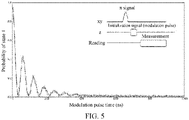
- FIG. 5 shows a group of experimental data, which shows a relationship in which the probability that the qubit is in the state 1 evolves with the time of the initialization signal (that is, the modulation pulse) with a given modulation frequency and a given modulation amplitude.
- a pulse sequence is as follows: First, a ⁇ pulse is added to an xy line of the qubit to excite the qubit to the state 1, the initialization signal (for example, a modulation pulse with a fixed amplitude and a variable length) in the present disclosure is then added to a z line, and finally, the state of the qubit is read. It can be learned from FIG.
- the population of the qubit in the state 1 is basically 0, that is, the qubit is basically in a state 0.
- the source of the oscillation thereof is an underdamping phenomenon formed by a strong coupling between the qubit and the resonant cavity.
- residual states 1 drop to below 0.2%, completing high-quality initialization.
- a qubit which originally consumes about 10 microseconds to decay, decays to a ground state in the order of hundreds of nanoseconds, and an initialization time is shortened by two orders of magnitude.
- residual states 1 caused by thermal excitation occupy about 4% when a system is in an equilibrium state, the residual states 1 can be reduced to below 0.2% through the solution.
- a state 1 originally caused by thermal excitation can be initialized to a state 0.
- the distribution of the qubits originally belonging to the state 0 in the state 1 region is significantly reduced.
- the reading fidelity of the state 0 is increased from 97.135% to 99.155%, and an error rate is reduced by 71%; and the reading fidelity of the state 1 is increased from 93.61% to 96.02%, and an error rate is reduced by 46%.
- a state 2 may be introduced and used for measurement.
- the related art herein may be implemented with reference to a document " Demonstrating a Driven Reset Protocol for a Superconducting Qubit" published by K. Geerlings et al., and details are not described in the present disclosure.
- the residual states 1 caused by thermal excitation are 2.8%.
- the residual states 1 after initialization are less than 0.2%.
- the initialization solution provided by the present disclosure has the following beneficial effects:
- the technical solutions of the present disclosure are applicable to a calculation process of any frequency-adjustable qubit.
- a quantum calculation process is divided into: calculation starting, performing a gate operation (the calculation process lasts for about several ⁇ s), and calculation ending. From a state in which one calculation ends to a state in which the next calculation starts, it is necessary to wait for a quantum system to return to an initial moment. If the waiting relies on the decay of the qubit itself, a waiting time of 100 ⁇ s is generally needed, which means that the next calculation can be performed probably only after a waiting time of 100 ⁇ s. If the initialization solution provided by the present disclosure is used, the qubit can be initialized in the order of hundreds of nanoseconds to a state in which the next calculation can be performed. In this way, the overall efficiency is greatly improved, and a quantity of times of calculations completed per unit time is increased from original 2 k times per second to 100 k times per second.
- the technical solutions of the present disclosure can be used for reducing a state error caused by thermal excitation, and initializing a state 1 caused by the thermal excitation to a state 0, thereby improving the reading fidelity. Further, because the reading fidelity is improved, a quantity of times required to obtain the same quality of reading can be reduced, thereby reducing a quantity of repetitions and improving efficiency.
- the present disclosure provides a technical solution for quickly initializing a superconducting qubit.
- the solution has high operability, an initialization speed in the order of hundreds of nanoseconds, and an effect of residual states 1 less than 0.2%, which can be applied to simultaneous initialization of a multi-bit system, and can improve the reading fidelity and greatly shorten the time required for a single calculation, thereby improving calculation efficiency.
- An exemplary embodiment of the present disclosure further provides a quantum processor.
- the quantum processor includes the quantum circuit described in the foregoing embodiments.
- An exemplary embodiment of the present disclosure further provides a quantum computer.
- the quantum computer includes the quantum circuit described in the foregoing embodiments.
Landscapes
- Engineering & Computer Science (AREA)
- General Physics & Mathematics (AREA)
- Theoretical Computer Science (AREA)
- Physics & Mathematics (AREA)
- Mathematical Analysis (AREA)
- Data Mining & Analysis (AREA)
- Evolutionary Computation (AREA)
- Condensed Matter Physics & Semiconductors (AREA)
- Computational Mathematics (AREA)
- Mathematical Optimization (AREA)
- Pure & Applied Mathematics (AREA)
- Computing Systems (AREA)
- General Engineering & Computer Science (AREA)
- Mathematical Physics (AREA)
- Software Systems (AREA)
- Artificial Intelligence (AREA)
- Superconductor Devices And Manufacturing Methods Thereof (AREA)
Abstract
Description
- This application claims priority to
Chinese Patent Application No. 202110112980.4, entitled "QUANTUM CIRCUIT AND QUANTUM PROCESSOR" and filed on January 27, 2021 - Embodiments of the present disclosure relate to the field of quantum technologies, and in particular, to a quantum circuit and a quantum processor.
- DiVincenzo proposed five standards (that is, DiVincenzo criteria) in 2000 to implement universal quantum computing, and one of the standards is an ability to initialize a quantum state to a ground state well.
- Embodiments of the present disclosure provide a quantum circuit and a quantum processor, to implement an efficient and high-precision qubit initialization solution. The technical solutions are as follows:
- According to an aspect of the embodiments of the present disclosure, a quantum circuit is provided, including: a qubit, a resonant cavity, and a feeder, the resonant cavity being coupled to the qubit, and the feeder being coupled to the qubit. The feeder is configured to feed an initialization signal to the qubit, the initialization signal being a modulation signal used for causing a frequency of the qubit to generate an oscillation. The oscillation causes an equivalent state exchange to occur between the qubit and the resonant cavity, and an excited state of the qubit is initialized to a ground state by using the resonant cavity.
- According to another aspect of the embodiments of the present disclosure, a quantum processor is provided. The quantum processor includes the foregoing quantum circuit.
- According to another aspect of the embodiments of the present disclosure, a quantum computer is provided. The quantum computer includes the foregoing quantum circuit.
- The technical solutions provided in the embodiments of the present disclosure may bring the following beneficial effects.
- The present disclosure provides an efficient and high-precision qubit initialization solution. In the technical solutions of the present disclosure, a modulation signal is applied to a qubit as an initialization signal, so that an excited state of the qubit quickly decays to a ground state by using a resonant cavity, thereby implementing rapid and high-fidelity initialization. In addition, in such a solution, a feedback loop does not need to be introduced to measure and read a state of the qubit, thereby reducing requirements for hardware.
- To describe technical solutions in embodiments of the present disclosure more clearly, the following briefly introduces the accompanying drawings required for describing the embodiments. Apparently, the accompanying drawings in the following description show only some embodiments of the present disclosure, and a person of ordinary skill in the art may still derive other accompanying drawings from these accompanying drawings without creative efforts.
-
FIG. 1 is a schematic diagram of a quantum circuit according to an embodiment of the present disclosure. -
FIG. 2 is a schematic diagram of an equivalent circuit corresponding to the quantum circuit inFIG. 1 . -
FIG. 3 is a schematic diagram of a change status of a frequency of a qubit with a pulse amplitude of an initialization signal. -
FIG. 4 is a comparison diagram of probabilities of astate 1 that are obtained from an experimental result of magnetic flux modulation and a simulation result. -
FIG. 5 is a schematic diagram of evolution of a probability of astate 1 with time at a given modulation frequency and amplitude. -
FIG. 6 is a comparison diagram of reading fidelities before initialization and after initialization. -
FIG. 7 is a comparison diagram of ratio ofresidual state 1 before initialization and after initialization. -
FIG. 8 is a schematic diagram of probabilities of astate 1 that are obtained when modulation frequencies are scanned at a fixed modulation time. - To make objectives, technical solutions, and advantages of the present disclosure clearer, the following further describes implementations of the present disclosure in detail with reference to the accompanying drawings.
- A quantum computer is a machine that performs calculations through the principle of quantum mechanics. Based on the superposition principle of quantum mechanics and quantum entanglement, the quantum computer has relatively strong parallel processing capabilities and can resolve some problems that are difficult for a classical computer to calculate. The zero resistance characteristic of superconducting qubits and a manufacturing process close to that of integrated circuits make a quantum computing system constructed by using superconducting qubits one of the most promising systems currently for implementing practical quantum computing.
- A quantum processor refers to a quantum-level computer processor, that is, a processor of a quantum computer. The quantum processor includes one or more quantum chips.
- The quantum chip (or referred to as a quantum circuit) is a central processing unit of a quantum computer, and is a core component in the quantum computer. The quantum chip is to integrate quantum circuits on a substrate to further carry a function of quantum information processing. With reference to the development history of conventional computers, to achieve commercialization and industrial upgrading, the quantum computer research needs to take the path of integration after overcoming a bottleneck problem. Superconducting systems, semiconductor quantum dot systems, micro-nano photonics systems, and even atomic and ionic systems all want to move onto chips. In terms of development, superconducting quantum chip systems are technologically ahead of other physical systems. Conventional semiconductor quantum dot systems are also a goal that people put effort into exploring, since the development of the conventional semiconductor industry is already very mature after all. For example, once semiconductor quantum chips break through a threshold of fault-tolerant quantum computing in terms of decoherence time and manipulation accuracy, it is expected that the existing achievements of the conventional semiconductor industry will be integrated to save development costs.
- In view of the advantages of quantum computers, quantum computers can be used for some processing and calculations in the future. For example, quantum computers can be used for some processing and calculations in systems built based on cloud technologies, to provide better services.
- Different from a case that such conventional classical physical quantities as a low level and a high level represent 0 and 1, in quantum computing, physical quantities such as the spin of an electron and the polarization of light are used as a
state 0 and astate 1 of a qubit. The mightiness of quantum computing lies in the use of the superposition of quantum states in coordination with quantum algorithms for parallel computing or simulation. Superconducting quantum computing is to construct equivalent energy levels by using Josephson junctions (a device with a Josephson effect with a superconductor-insulator-superconductor structure, which is a key part of constructing superconducting qubits). A ground state in the constructed energy levels is equivalent to 0, and a first excited state is equivalent to 1. Without performing any operation, an ideal quantum system is 100% in astate 0. However, because the temperature is still in the order of tens of mK (millikelvin degrees), a small amount of thermal excitation is caused, and there are still someresidual states 1. Theresidual states 1 follow the Maxwell-Boltzmann distribution:
- P 〈i〉 represents a probability that a qubit i is in a
state 1, i is labels of different qubits,
state 1 caused by the residual thermal excitation to astate 0 and improve the fidelity of initialization to enable the entire system to be initialized with high efficiency and high precision is a very important issue. - In a feedback-based initialization solution provided by the related art, on the one hand, it is necessary to perform measurement and read whether a qubit is in a
state 0 or astate 1, and in a measurement and reading process, a state of the qubit is affected. For example, the state of the qubit is originally just the superposition of thestate 0 and thestate 1, and due to impact of the measurement and reading, mixing of states is caused such as introducing a state in another subspace and causing a state leakage, which results in relatively low reading fidelity. Furthermore, a π pulse applied to the qubit is also limited by precision. As a result, relatively low initialization precision is caused in general. On the other hand, due to the introduction of a feedback loop for measurement and reading of the state of the qubit, requirements for hardware are also relatively high. - The present disclosure provides an efficient and high-precision qubit initialization solution. Qubit initialization is to prepare a qubit into a known quantum state such as a
state 0 of the qubit. In the technical solutions of the present disclosure, a state of a qubit does not need to be measured or read. A modulation signal is applied on the qubit as an initialization signal to modulate a magnetic flux of the qubit, so that an excited state (such as state 1) of the qubit quickly decays to a ground state (that is, state 0) by using a resonant cavity, thereby implementing rapid and high-fidelity initialization. In addition, in such a solution, a feedback loop does not need to be introduced to measure and read the state of the qubit, thereby reducing requirements for hardware. The technical solutions of the present disclosure are described in detail below by using a plurality of embodiments. -
FIG. 1 is a schematic diagram of a quantum circuit according to an embodiment of the present disclosure. The quantum circuit includes aqubit 11, aresonant cavity 12, and afeeder 13. - In this embodiment of the present disclosure, the
qubit 11 is a frequency-adjustable qubit. That is, the frequency of the qubit is adjustable. The frequency of the qubit is adjusted by applying a specific signal to the qubit. For example, thequbit 11 is a frequency-adjustable superconducting qubit. - In addition, the
qubit 11 is any type of qubit with adjustable frequency, for example, a Transmon qubit. Transmon is a type of superconducting qubit, which is characterized in that a large capacitor is connected in parallel to reduce the impact of charge noise on the qubit, and the frequency is adjustable. In some other examples, thequbit 11 is another type of qubit with adjustable frequency, for example, a flux qubit, a charge qubit, or a phase qubit. This is not limited in the embodiments of the present disclosure. - As shown in
FIG. 1 , the quantum circuit further includes areading line 14. Theresonant cavity 12 is coupled to thereading line 14, and theresonant cavity 12 is further coupled to thequbit 11. For example, theresonant cavity 12 and thereading line 14 are inductively coupled to each other, and theresonant cavity 12 and thequbit 11 are capacitively coupled to each other. In an embodiment, a coupling strength between theresonant cavity 12 and thequbit 11 is approximately 100 MHz. Thereading line 14 and theresonant cavity 12 are configured to read a state of thequbit 11. Specifically, when thequbit 11 is in different states, the frequency of theresonant cavity 12 presents different characteristics. Thereading line 14 can learn the state of thequbit 11 by reading the frequency of theresonant cavity 12. Thereading line 14 and theresonant cavity 12 described herein are configured to measure and read the state of thequbit 11 in a process of quantum computing. However, in a process of initializing thequbit 11 in the present disclosure, the state of thequbit 11 does not need to be measured or read. Regardless of which state thequbit 11 is in, an initialization signal in the present disclosure is directly applied to thequbit 11. - As shown in
FIG. 1 , the quantum circuit provided in this embodiment of the present disclosure further includes thefeeder 13 coupled to thequbit 11. Thefeeder 13 is configured to feed an initialization signal to thequbit 11. The initialization signal is a modulation signal such as a modulation pulse signal (briefly referred to as a "modulation pulse") used for causing the frequency of thequbit 11 to generate an oscillation. Further, the oscillation causes an equivalent state exchange to occur between thequbit 11 and theresonant cavity 12, so that an excited state of thequbit 11 is initialized to a ground state by using theresonant cavity 12. - A coupling part of the
qubit 11 and thereading line 14 and a coupling part of thefeeder 13 and thequbit 11 are not limited to shapes shown inFIG. 1 . - In an embodiment, when an energy level of a sideband generated by the oscillation and an energy level of the
resonant cavity 12 meet a proximity condition, an equivalent state exchange occurs between thequbit 11 and theresonant cavity 12. Theresonant cavity 12 is equivalent to a cold store. Because a decay coefficient of theresonant cavity 12 is high, theresonant cavity 12 can quickly decay the excited state of thequbit 11, so as to initialize thequbit 11 to the ground state, that is, quickly initialize thequbit 11 from astate 1 to astate 0. Because a photon in theresonant cavity 12 has a decay rate that is high and a decay time that is approximately 30 to 80 ns, the resonant cavity is relatively suitably used as a channel for rapidly decaying the energy of thequbit 11, to quickly decay thequbit 11 from the excited state to the ground state. - In an embodiment, the proximity condition means that the energy level of the sideband is equal to the energy level of the
resonant cavity 12, or a difference between the energy level of the sideband and the energy level of theresonant cavity 12 is less than a threshold, the threshold being a preset value, or a modulation frequency of the initialization signal approaches 1/N of an energy level difference, where the energy level difference refers to a difference between the energy level of the sideband and the energy level of theresonant cavity 12, and N is a value such as 2, 3, or 4. This is not limited in the embodiments of the present disclosure. -
FIG. 2 is a schematic diagram of an equivalent circuit corresponding to the quantum circuit inFIG. 1 . In the equivalent circuit shown inFIG. 2 , the equivalent circuit of thequbit 11 includes acoupling capacitor 111 and a superconducting quantum interference device (SQUID) 112 including two Josephson junctions. Theresonant cavity 12 and thequbit 11 are capacitively coupled, and theresonant cavity 12 and thereading line 14 are inductively coupled. In an embodiment, thefeeder 13 is a magnetic flux bias line, which can generate magnetic flux in a double-junction region of theSQUID 112 to adjust the frequency and an energy level of thequbit 11. The magnetic flux bias line may also be referred to as a z line. A coupling manner between the feeder 13 (such as a magnetic flux bias line) and thequbit 11 is not limited in this embodiment of the present disclosure. For example, an inductive coupling is adopted between thefeeder 13 and thequbit 11. - As shown in
FIG. 3 , aline 31 represents a change status of the frequency of the qubit with a pulse amplitude of the initialization signal. If a modulation pulse shown by aline 32 inFIG. 3 is applied to the z line inFIG. 2 , the frequency of the qubit generates an oscillation near a sweet spot (which is an optimal operating point) and the oscillation generates a sideband with a frequency of ωq + ω, where ωq represents the frequency of the qubit, and ω represents a modulation frequency of the initialization signal (that is, the foregoing modulation pulse). When the frequency or an energy level of the sideband approaches a frequency or an energy level of the resonant cavity, a population ofstates 1 of the qubit transfers to the resonant cavity. The resonant cavity is equivalent to a cold store, which quickly initializes an excited state of the qubit to a ground state, that is, quickly initializes the qubit from thestate 1 to thestate 0. This is because a case that the energy level of the sideband approaches the energy level of the resonant cavity is equivalent to a case that a quantum state exchange occurs between the qubit and the resonant cavity. However, due to quite fast decay in the resonant cavity, thestates 1 of the qubit are quickly leaked, that is, an initialization process is implemented. - In an embodiment,

- Φ represents the initialization signal, A represents a modulation amplitude of the initialization signal, ω represents a modulation frequency of the initialization signal, φ represents a modulation phase of the initialization signal, and t represents time. The initialization signal is generated by any waveform generator. As long as such three parameters as A, ω, and φ are provided to the waveform generator, a modulation signal that meets requirements of the parameters can be generated by using the waveform generator.
- In the qubit initialization solution provided by this embodiment of the present disclosure, only a waveform generator needs to be added to generate the initialization signal. Both the magnetic flux bias line and the resonant cavity used in the initialization process are components originally required by the quantum circuit, and there is no need to add another resonant cavity or control line. Therefore, requirements for hardware are quite low.
- In an exemplary embodiment, when the operating point of the qubit is close to the sweet spot, a modulation order of the initialization signal is an even number greater than or equal to 2. When the operating point of the qubit is far away from the sweet spot, the modulation order of the initialization signal is an integer greater than or equal to 1. The operating point of the qubit refers to a frequency of the qubit in an initialization state. The sweet spot of the qubit may also be referred to as a center point, an optimal operating point, or another name, which indicates a frequency position at which the qubit is not sensitive to noise, and the coherence of the qubit is relatively good. The operating point of the qubit is determined through artificial selection. For example, the operating point of the qubit is selected near the sweet spot, so that the operating point is close to the sweet spot. Alternatively, the operating point of the qubit is selected far away from the sweet spot. In an embodiment of the present disclosure, "close" and "far away from" described above are distinguished by using a threshold. For example, when a frequency difference between the operating point of the qubit and the sweet spot of the qubit is less than the threshold, it is determined that the operating point is close to the sweet spot; and when the frequency difference between the operating point of the qubit and the sweet spot of the qubit is greater than the threshold, it is determined that the operating point is far away from the sweet spot. The threshold is set according to an actual situation, and is not limited in the present disclosure.
- In addition, the foregoing conclusion of determining the modulation order can be obtained through actual experiments or simulation experiments. Through experiments, an initialization signal is applied to a qubit, a modulation frequency and a modulation order of the initialization signal are adjusted, and a probability that the qubit is in a
state 1 is then measured. It is found that if an operating point of the qubit is close to a sweet spot, an initialization effect achieved by using second-order modulation, fourth-order modulation, or higher-even-number-order modulation is better (that is, the probability that the qubit is in thestate 1 is lower). When the operating point of the qubit is far away from the sweet spot, a better initialization effect can be achieved by using first-order modulation, second-order modulation, or higher-order modulation. In addition, a modulation signal with an order that is used can also be obtained through the above experiment, and a purpose is to make the probability that the qubit is in thestate 1 as low as possible. - In an embodiment, the modulation frequency of the initialization signal is approximately one Nth of a difference between the frequency of the qubit and the frequency of the resonant cavity, and N is the modulation order of the initialization signal. That is, after the modulation order N of the initialization signal is determined, the modulation frequency of the initialization signal is further determined with reference to the modulation order N and the foregoing frequency difference. For example,

- where ω represents the modulation frequency of the initialization signal, δ is the frequency difference between the qubit and the resonant cavity (that is, the difference between the frequency of the qubit and the frequency of the resonant cavity), N is the modulation order of the initialization signal, and α is an allowable deviation range. For example, α is a value and represents an allowable deviation value, or α is a value range, the value range of α can be determined through the foregoing formula, and any value within the value range can be used as the modulation frequency of the initialization signal. The allowable deviation range is determined with reference to experiments or actual experience, and this is not limited in the present disclosure.
- The initialization solution provided by the present disclosure is implemented by using a coupling interaction between the resonant cavity and the qubit. A system Hamiltonian

Hamiltonian 


where ωq is the frequency of the qubit, η is an anharmonicity constant of the qubit, and a +, a and b +, b are ladder operators of the qubit and the resonant cavity respectively, and g is a coupling strength (about 100 MHz) between the qubit and the resonant cavity. For example, ωq of the qubit and magnetic flux added to the z line inFIG. 3 are simplified as:
where Ec is the electrostatic energy of the qubit, EJ is the energy of the SQUID, d is related to the symmetry of the two junctions, and Φ0 is a magnetic flux quantum. The parameters are all fixed values after a qubit is given. When the initialization signal Φ vibrates in the form of Φ = Acos(ωt + φ), A is the modulation amplitude, ω is the modulation frequency, φ is the modulation phase, and t is time. A caused change of the frequency ωq of the qubit is substituted into an overall Hamiltonian
state 1 by using a π pulse, a simulation result shown on the right side ofFIG. 4 can be obtained. Similar to measured data obtained from an actual experimental result shown on the left side ofFIG. 4 , color depth in the figure represents a residual quantity ofstates 1, and a color closer to black indicates a better initialization effect. - A derivation process is as follows: The overall Hamiltonian of the system is:

- After rotating wave approximation is performed by using the frequency of the qubit and the frequency of the resonant cavity as reference frames, the following formula can be obtained:

where δis the frequency difference between the qubit and the resonant cavity, and the frequency of the qubit is simplified as:
where ω q0 is a center point frequency of an oscillation, Δ is the modulation frequency of the initialization signal (which is equivalent to ω in the foregoing formula Φ = Acos(ωt + φ)), and t is time. - Then,

expansion is performed according to Bessel orders:
- Therefore, when nΔ + δ = 0 or nΔ - δ = 0, an equivalent resonance interaction occurs:

- Jn is an nth Bessel order coefficient,

FIG. 4 . In addition, if the operating point of the qubit is near the sweet spot, because the modulation thereof is symmetrical and there is no direct current component, the modulation order n in the above formula can only be an even number, and the modulation order is 2, 4, 6, or the like. If the operating point of the qubit is not near the sweet spot, because the modulation thereof is asymmetrical and there is a direct current component, the modulation order n in the above formula may be any positive integer. For example, the modulation order is 1, 2, 3, 4, or the like. - It can be seen from
FIG. 4 that the experimental result is basically consistent with the simulation result. In addition, it can also be verified that the solution of the present disclosure is feasible in principle. Under frequency modulation, the population of the qubit in thestate 1 can be rapidly decayed by using the resonant cavity. - Based on the above, the present disclosure provides an efficient and high-precision qubit initialization solution. In the technical solutions of the present disclosure, a modulation signal is applied to a qubit as an initialization signal, so that an excited state of the qubit quickly decays to a ground state by using a resonant cavity, thereby implementing rapid and high-fidelity initialization. In addition, in such a solution, a feedback loop does not need to be introduced to measure and read the state of the qubit, thereby reducing requirements for hardware.
- When the quantum circuit includes a plurality of qubits (that is, is a multi-bit system), because each qubit corresponds to a feeder (for example, a magnetic flux bias line), corresponding initialization signals are respectively applied to the qubits to simultaneously initialize the plurality of qubits. Further, parameters such as a modulation frequency, a modulation amplitude, and a modulation phase of the corresponding initialization signal applied to each qubit may be set specifically according to characteristics of the each qubit. That is, initialization signals with different parameters are applied to different qubits, so that each qubit achieves a better initialization effect.
- In addition, regardless of whether the quantum circuit includes a single qubit or a plurality of qubits, in the initialization solution provided by the present disclosure, a state of each qubit does not need to be measured or read to further decide whether to apply an initialization signal to the qubit based on the state. In the initialization solution provided by the present disclosure, regardless of which state the qubit is in, the corresponding initialization signal can be directly applied. A state of a qubit originally in a ground state does not change, an equivalent state exchange occurs between a qubit originally in an excited state and a resonant cavity, and the resonant cavity initializes the qubit from the excited state to a ground state, thereby initializing all qubits to a ground state.
-
FIG. 5 shows a group of experimental data, which shows a relationship in which the probability that the qubit is in thestate 1 evolves with the time of the initialization signal (that is, the modulation pulse) with a given modulation frequency and a given modulation amplitude. A pulse sequence is as follows: First, a π pulse is added to an xy line of the qubit to excite the qubit to thestate 1, the initialization signal (for example, a modulation pulse with a fixed amplitude and a variable length) in the present disclosure is then added to a z line, and finally, the state of the qubit is read. It can be learned fromFIG. 5 that after a modulation pulse of approximately 500 ns, the population of the qubit in thestate 1 is basically 0, that is, the qubit is basically in astate 0. In addition, it can be learned fromFIG. 5 that the probability that the qubit is in thestate 1 presents a decreasing trend of an oscillation with the length of the modulation pulse. The source of the oscillation thereof is an underdamping phenomenon formed by a strong coupling between the qubit and the resonant cavity. After measurement at the first valley bottom (about 31 ns),residual states 1 drop to below 0.2%, completing high-quality initialization. A qubit, which originally consumes about 10 microseconds to decay, decays to a ground state in the order of hundreds of nanoseconds, and an initialization time is shortened by two orders of magnitude. Through measurement, ifresidual states 1 caused by thermal excitation occupy about 4% when a system is in an equilibrium state, theresidual states 1 can be reduced to below 0.2% through the solution. - Through the initialization solution provided by the present disclosure, a
state 1 originally caused by thermal excitation can be initialized to astate 0. As shown on the left side ofFIG. 6 , there are also some qubits originally belonging to astate 0 distributed in astate 1 region, and such a distribution affects the reading fidelity of qubits. As shown on the right side ofFIG. 6 , after the initialization signal in the present disclosure is applied, the distribution of the qubits originally belonging to thestate 0 in thestate 1 region is significantly reduced. In terms of fidelity, the reading fidelity of thestate 0 is increased from 97.135% to 99.155%, and an error rate is reduced by 71%; and the reading fidelity of thestate 1 is increased from 93.61% to 96.02%, and an error rate is reduced by 46%. - For a proportion of the
residual states 1, astate 2 may be introduced and used for measurement. The related art herein may be implemented with reference to a document "Demonstrating a Driven Reset Protocol for a Superconducting Qubit" published by K. Geerlings et al., and details are not described in the present disclosure. As shown on the left side ofFIG. 7 , if no initialization operation is performed, theresidual states 1 caused by thermal excitation are 2.8%. However, as shown on the right side ofFIG. 7 , theresidual states 1 after initialization are less than 0.2%. - It can be seen from
FIG. 8 that if modulation frequencies are scanned in a fixed modulation time, a good initialization effect can be achieved in a relatively large frequency range (395 MHz to 403 MHz), which indicates that in the initialization solution provided by the present disclosure, there is a quite large surplus in parameter selection, and the robustness of the solution is high. - Therefore, in general, the initialization solution provided by the present disclosure has the following beneficial effects:
- (1) The initialization solution provided by the present disclosure is essentially to generate a sideband close to a resonant cavity through the modulation of a frequency of a qubit, and to achieve an initialization effect by using the characteristic of rapid decay of the resonant cavity. The resonant cavity is equivalent to an iceberg. Any excited state (state 1) interacting with the resonant cavity is rapidly cooled to a ground state (state 0). Therefore, through the initialization solution, the qubit can be quickly initialized so that a next calculation can be performed, thereby greatly shortening the time for a single calculation. A frequency of completing a calculation per unit time is increased from 2 kHz to 100 kHz.
- The technical solutions of the present disclosure are applicable to a calculation process of any frequency-adjustable qubit. A quantum calculation process is divided into: calculation starting, performing a gate operation (the calculation process lasts for about several µs), and calculation ending. From a state in which one calculation ends to a state in which the next calculation starts, it is necessary to wait for a quantum system to return to an initial moment. If the waiting relies on the decay of the qubit itself, a waiting time of 100 µs is generally needed, which means that the next calculation can be performed probably only after a waiting time of 100 µs. If the initialization solution provided by the present disclosure is used, the qubit can be initialized in the order of hundreds of nanoseconds to a state in which the next calculation can be performed. In this way, the overall efficiency is greatly improved, and a quantity of times of calculations completed per unit time is increased from original 2 k times per second to 100 k times per second.
- (2) The technical solutions of the present disclosure can be used for reducing a state error caused by thermal excitation, and initializing a
state 1 caused by the thermal excitation to astate 0, thereby improving the reading fidelity. Further, because the reading fidelity is improved, a quantity of times required to obtain the same quality of reading can be reduced, thereby reducing a quantity of repetitions and improving efficiency. - (3) The technical solutions of the present disclosure are compatible with an existing frequency-adjustable chip system. A modulation pulse is added to a z line to initialize the qubit with high fidelity in the order of hundreds of nanoseconds. Therefore, the initialization speed and quality are both superior to those of previous solutions.
- (4) Through experiments, it is found that the technical solutions of the present disclosure have no visible impact on the frequency and other parameters of adjacent qubits, and are suitable for simultaneous initialization of a multi-bit system.
- Based on the above technical points, the present disclosure provides a technical solution for quickly initializing a superconducting qubit. The solution has high operability, an initialization speed in the order of hundreds of nanoseconds, and an effect of
residual states 1 less than 0.2%, which can be applied to simultaneous initialization of a multi-bit system, and can improve the reading fidelity and greatly shorten the time required for a single calculation, thereby improving calculation efficiency. - An exemplary embodiment of the present disclosure further provides a quantum processor. The quantum processor includes the quantum circuit described in the foregoing embodiments.
- An exemplary embodiment of the present disclosure further provides a quantum computer. The quantum computer includes the quantum circuit described in the foregoing embodiments.
- It is to be understood that "plurality of" mentioned in the specification means two or more.
- The foregoing descriptions are merely exemplary embodiments of the present disclosure, but are not intended to limit the present disclosure. Any modification, equivalent replacement, or improvement made within the spirit and principle of the present disclosure shall fall within the protection scope of the present disclosure.
Claims (10)
- A quantum circuit, comprising: a qubit, a resonant cavity, and a feeder, the resonant cavity being coupled to the qubit, and the feeder being coupled to the qubit, wherein:the feeder is configured to feed an initialization signal to the qubit, the initialization signal being a modulation signal for causing a frequency of the qubit to generate an oscillation; andthe oscillation causes an equivalent state exchange to occur between the qubit and the resonant cavity, so as to enable a transition from an excited state of the qubit to a ground state by using the resonant cavity.
- The quantum circuit according to claim 1, wherein

- The quantum circuit according to claim 1, wherein the feeder is a magnetic flux bias line.
- The quantum circuit according to claim 1, wherein when an energy level of a sideband generated by the oscillation and an energy level of the resonant cavity meet a proximity condition, the equivalent state exchange occurs between the qubit and the resonant cavity.
- The quantum circuit according to any one of claims 1 to 4, wherein when a frequency difference between an operating point of the qubit and a sweet spot is less than a threshold, a modulation order of the initialization signal is an even number greater than or equal to 2, wherein the operating point of the qubit refers to a frequency of the qubit in an initialization state.
- The quantum circuit according to any one of claims 1 to 4, wherein when a frequency difference between an operating point of the qubit and a sweet spot is greater than a threshold, a modulation order of the initialization signal is an integer greater than or equal to 1, wherein the operating point of the qubit refers to a frequency of the qubit in an initialization state.
- The quantum circuit according to any one of claims 1 to 4, wherein

- The quantum circuit according to any one of claims 1 to 4, wherein the qubit is a frequency-adjustable superconducting qubit.
- A quantum processor, comprising the quantum circuit according to any one of claims 1 to 8.
- A quantum computer, comprising the quantum circuit according to any one of claims 1 to 8.
Applications Claiming Priority (2)
| Application Number | Priority Date | Filing Date | Title |
|---|---|---|---|
| CN202110112980.4A CN113326944B (en) | 2021-01-27 | 2021-01-27 | Quantum circuit and quantum processor |
| PCT/CN2021/117309 WO2022160725A1 (en) | 2021-01-27 | 2021-09-08 | Quantum circuit and quantum processor |
Publications (2)
| Publication Number | Publication Date |
|---|---|
| EP4064137A1 true EP4064137A1 (en) | 2022-09-28 |
| EP4064137A4 EP4064137A4 (en) | 2022-12-21 |
Family
ID=77413481
Family Applications (1)
| Application Number | Title | Priority Date | Filing Date |
|---|---|---|---|
| EP21844599.7A Pending EP4064137A4 (en) | 2021-01-27 | 2021-09-08 | QUANTUM CIRCUIT AND QUANTUM PROCESSOR |
Country Status (6)
| Country | Link |
|---|---|
| US (1) | US12001922B2 (en) |
| EP (1) | EP4064137A4 (en) |
| JP (1) | JP7301221B2 (en) |
| KR (1) | KR102824319B1 (en) |
| CN (1) | CN113326944B (en) |
| WO (1) | WO2022160725A1 (en) |
Families Citing this family (23)
| Publication number | Priority date | Publication date | Assignee | Title |
|---|---|---|---|---|
| CN113326944B (en) * | 2021-01-27 | 2022-03-25 | 腾讯科技(深圳)有限公司 | Quantum circuit and quantum processor |
| JP2024526085A (en) | 2021-06-11 | 2024-07-17 | シーク, インコーポレイテッド | Flux bias system and method for superconducting quantum circuits |
| CN114169529B (en) * | 2021-11-17 | 2025-03-14 | 山东浪潮科学研究院有限公司 | A quantum bit reading optimization method, device and computer medium |
| CN114386609A (en) * | 2021-12-23 | 2022-04-22 | 广东浪潮智慧计算技术有限公司 | A superconducting qubit and superconducting qubit system |
| CN116702916B (en) * | 2022-02-28 | 2024-07-16 | 本源量子计算科技(合肥)股份有限公司 | Testing method and device for adjustable coupling bit quantum information leakage |
| CN116702910B (en) * | 2022-02-28 | 2024-07-16 | 本源量子计算科技(合肥)股份有限公司 | Quantum information leakage testing method and device for quantum bit device |
| CN114595821B (en) * | 2022-03-21 | 2025-05-30 | 北京百度网讯科技有限公司 | Quantum circuit and control method thereof, superconducting quantum chip and superconducting quantum computer |
| CN116957085B (en) * | 2022-04-18 | 2025-10-10 | 本源量子计算科技(合肥)股份有限公司 | Error measurement method and device for two-bit quantum logic gate and quantum computer |
| CN114970865B (en) * | 2022-05-25 | 2023-03-10 | 北京百度网讯科技有限公司 | Quantum circuit processing method and device on quantum chip and electronic equipment |
| US20240005191A1 (en) * | 2022-05-27 | 2024-01-04 | Nord Quantique inc. | Generalized transmon reset method and multimode quantum computing system using same |
| CN114861924B (en) * | 2022-05-27 | 2025-07-15 | 本源量子计算科技(合肥)股份有限公司 | A reading circuit, a reading method and a quantum computer |
| CN117273153B (en) * | 2022-06-14 | 2026-01-13 | 本源量子计算科技(合肥)股份有限公司 | Qubit frequency drive signal generator and quantum computer system |
| US12099903B2 (en) | 2022-07-18 | 2024-09-24 | International Business Machines Corporation | Dynamic adaptive thresholding for qubit reset |
| CN115907018B (en) * | 2022-09-21 | 2024-07-02 | 北京量子信息科学研究院 | Device for controlling quantum bit, quantum chip and control method |
| CN115860129B (en) * | 2022-11-16 | 2026-03-27 | 深圳季轴量子有限公司 | Quantum bit processing methods, quantum circuits and quantum computers |
| CN115759274A (en) * | 2022-11-16 | 2023-03-07 | 阿里巴巴达摩院(杭州)科技有限公司 | Quantum bit processing method, computer readable storage medium and computer equipment |
| CN115632712B (en) * | 2022-11-30 | 2023-03-21 | 苏州浪潮智能科技有限公司 | Demultiplexer and system, method and device for measuring qubit state |
| CN116011578B (en) * | 2022-12-02 | 2024-07-30 | 浙江大学 | Universal frequency modulation method applied to quantum bit system |
| CN116187258B (en) * | 2023-01-16 | 2023-12-05 | 北京百度网讯科技有限公司 | Quantum chip layout simulation method and device, computing equipment and storage medium |
| CN115829046B (en) * | 2023-02-15 | 2023-05-05 | 苏州浪潮智能科技有限公司 | Quantum signal determination method and related device |
| KR102833710B1 (en) * | 2023-06-02 | 2025-07-14 | (주)코리아 싸인 | Device of generating quantum field for applying to lighting and video display devices |
| CN117497070B (en) * | 2023-11-02 | 2024-05-14 | 正则量子(北京)技术有限公司 | A method and device for solving eigenvalues based on controllable Hamiltonian evolution |
| CN117669749B (en) * | 2023-11-14 | 2025-04-22 | 北京百度网讯科技有限公司 | Quantum bit parameter calibration method, device, electronic device and storage medium |
Family Cites Families (21)
| Publication number | Priority date | Publication date | Assignee | Title |
|---|---|---|---|---|
| DE69530911D1 (en) * | 1995-03-07 | 2003-07-03 | St Microelectronics Srl | Voltage controlled oscillator with a wide frequency range and with little trembling |
| FR2862151B1 (en) * | 2003-11-07 | 2007-08-24 | Commissariat Energie Atomique | DEVICE FOR RESETTING A QUANTUM BIT DEVICE WITH TWO ENERGY CONDITIONS |
| US8022722B1 (en) * | 2010-06-04 | 2011-09-20 | Northrop Grumman Systems Corporation | Quantum logic gates utilizing resonator mediated coupling |
| CN104297704B (en) * | 2013-07-19 | 2017-04-26 | 中国科学院上海微系统与信息技术研究所 | Resetting system and superconductive quantum interference sensor suitable for same |
| EP3262572B1 (en) * | 2015-02-27 | 2024-04-03 | Yale University | Techniques of oscillator control for quantum information processing and related systems and methods |
| US10250271B2 (en) * | 2015-10-07 | 2019-04-02 | Kabushiki Kaisha Toshiba | Quantum computation apparatus and quantum computation method |
| SG11201803545QA (en) * | 2015-10-29 | 2018-05-30 | Google Llc | Removing leakage in a quantum bit |
| CN205879109U (en) * | 2016-06-27 | 2017-01-11 | 沈阳工程学院 | Electromagnetic coupling synthesizes detecting device |
| AU2016432064B2 (en) * | 2016-12-07 | 2020-03-19 | Google Llc | Quantum bit multi-state reset |
| US10483980B2 (en) * | 2017-06-19 | 2019-11-19 | Rigetti & Co, Inc. | Parametrically activated quantum logic gates |
| US10223643B1 (en) * | 2017-09-29 | 2019-03-05 | International Business Machines Corporation | Reduction and/or mitigation of crosstalk in quantum bit gates |
| US11710058B2 (en) | 2018-06-30 | 2023-07-25 | Intel Corporation | Apparatus and method for recompilation of quantum circuits to compensate for drift in a quantum computer |
| CN111222644B (en) * | 2018-11-26 | 2023-09-26 | 华为技术有限公司 | A method of controlling qubits in superconducting chips and related equipment |
| US10958274B2 (en) * | 2019-03-01 | 2021-03-23 | Anyon Systems Inc. | Microwave device and method of operation |
| EP3959666A1 (en) * | 2019-06-27 | 2022-03-02 | Google LLC | Probe of qubit-resonator dispersive shift using ac stark shift |
| CN110490327B (en) * | 2019-07-23 | 2023-07-18 | 湖北工业大学 | Quantum computer quantum processing unit, quantum circuit and quantum circuit quantum algorithm |
| CN111612151B (en) | 2020-05-27 | 2023-06-16 | 山东浪潮科学研究院有限公司 | A control method, system and related components of a quantum computer |
| CN111652376B (en) * | 2020-07-03 | 2024-02-27 | 本源量子计算科技(合肥)股份有限公司 | A method and device for reading qubit signals |
| CN111967603B (en) * | 2020-09-01 | 2022-04-08 | 腾讯科技(深圳)有限公司 | Quantum chips, quantum processors and quantum computers |
| CN112232513B (en) * | 2020-10-28 | 2024-06-14 | 本源量子计算科技(合肥)股份有限公司 | A method and device for preparing a quantum state |
| CN113326944B (en) * | 2021-01-27 | 2022-03-25 | 腾讯科技(深圳)有限公司 | Quantum circuit and quantum processor |
-
2021
- 2021-01-27 CN CN202110112980.4A patent/CN113326944B/en active Active
- 2021-09-08 JP JP2022517154A patent/JP7301221B2/en active Active
- 2021-09-08 EP EP21844599.7A patent/EP4064137A4/en active Pending
- 2021-09-08 WO PCT/CN2021/117309 patent/WO2022160725A1/en not_active Ceased
- 2021-09-08 KR KR1020227026022A patent/KR102824319B1/en active Active
-
2022
- 2022-02-09 US US17/668,380 patent/US12001922B2/en active Active
Also Published As
| Publication number | Publication date |
|---|---|
| CN113326944B (en) | 2022-03-25 |
| KR20220123050A (en) | 2022-09-05 |
| EP4064137A4 (en) | 2022-12-21 |
| US20220269970A1 (en) | 2022-08-25 |
| CN113326944A (en) | 2021-08-31 |
| JP7301221B2 (en) | 2023-06-30 |
| KR102824319B1 (en) | 2025-06-25 |
| JP2023514895A (en) | 2023-04-12 |
| WO2022160725A1 (en) | 2022-08-04 |
| US12001922B2 (en) | 2024-06-04 |
Similar Documents
| Publication | Publication Date | Title |
|---|---|---|
| US12001922B2 (en) | Quantum circuit and quantum processor | |
| US20260047354A1 (en) | Systems, devices, and methods to interact with quantum information stored in spins | |
| US12204991B1 (en) | Gate formation on a quantum processor | |
| US8631367B2 (en) | Methods of increasing fidelity of quantum operations | |
| US8089286B2 (en) | System and method for quantum computer calibration and performance estimation | |
| US8315969B2 (en) | Estimating a quantum state of a quantum mechanical system | |
| JP2022551207A (en) | Quantum chips, quantum processors and quantum computers | |
| US11910728B2 (en) | Flopping-mode electric dipole spin resonance | |
| Alam et al. | Quantum computing hardware for HEP algorithms and sensing | |
| US20230409942A1 (en) | Applying Two-qubit Quantum Logic Gates in a Superconducting Quantum Processing Unit | |
| Grajcar et al. | Possible implementation of adiabatic quantum algorithm with superconducting flux qubits | |
| US12099902B2 (en) | Quantum gate device | |
| US20230376816A1 (en) | Method and device for quantum computing with majorana modes | |
| HK40050615A (en) | A quantum circuit and quantum processor | |
| HK40050615B (en) | A quantum circuit and quantum processor | |
| Ralston et al. | New phenomena in propagation of radio polarizations due to magnetic fields on cosmological scales | |
| Aarab et al. | State initialization of a hot spin qubit in a double quantum dot by measurement-based quantum feedback control | |
| Li | Flip Chip Packaging for Superconducting Qubit: Design Methodology and Simulation | |
| US20240289671A1 (en) | Method for processing qubits, quantum circuit and non-transitory computer readable medium | |
| Shi | Designing Optical Quantum Computing With Minimal Hardware | |
| Li et al. | Fast and Robust Remote Two-Qubit Gates on Distributed Qubits | |
| EP4722991A1 (en) | Method and unit for characterizing a quantum system | |
| Guzman IV | Combining Squid Devices and Microwave Resonators for Coherent Control and Detection of Quantum Spins | |
| WO2025074113A1 (en) | Quantum information system | |
| Braccini et al. | Nonclassicality of a Macroscopic Qubit-Ensemble via Parity Measurement Induced Disturbance |
Legal Events
| Date | Code | Title | Description |
|---|---|---|---|
| STAA | Information on the status of an ep patent application or granted ep patent |
Free format text: STATUS: UNKNOWN |
|
| STAA | Information on the status of an ep patent application or granted ep patent |
Free format text: STATUS: THE INTERNATIONAL PUBLICATION HAS BEEN MADE |
|
| PUAI | Public reference made under article 153(3) epc to a published international application that has entered the european phase |
Free format text: ORIGINAL CODE: 0009012 |
|
| STAA | Information on the status of an ep patent application or granted ep patent |
Free format text: STATUS: REQUEST FOR EXAMINATION WAS MADE |
|
| 17P | Request for examination filed |
Effective date: 20220127 |
|
| AK | Designated contracting states |
Kind code of ref document: A1 Designated state(s): AL AT BE BG CH CY CZ DE DK EE ES FI FR GB GR HR HU IE IS IT LI LT LU LV MC MK MT NL NO PL PT RO RS SE SI SK SM TR |
|
| REG | Reference to a national code |
Ref country code: DE Ref legal event code: R079 Free format text: PREVIOUS MAIN CLASS: G06N0010000000 Ipc: G06N0010400000 |
|
| A4 | Supplementary search report drawn up and despatched |
Effective date: 20221122 |
|
| RIC1 | Information provided on ipc code assigned before grant |
Ipc: G06N 10/40 20220101AFI20221116BHEP |
|
| DAV | Request for validation of the european patent (deleted) | ||
| DAX | Request for extension of the european patent (deleted) | ||
| STAA | Information on the status of an ep patent application or granted ep patent |
Free format text: STATUS: EXAMINATION IS IN PROGRESS |
|
| 17Q | First examination report despatched |
Effective date: 20250702 |