EP4063972B1 - Holographisches anzeigesystem und verfahren zur erzeugung eines hologramms durch kompensation der aberration einer holographischen anzeigevorrichtung - Google Patents
Holographisches anzeigesystem und verfahren zur erzeugung eines hologramms durch kompensation der aberration einer holographischen anzeigevorrichtung Download PDFInfo
- Publication number
- EP4063972B1 EP4063972B1 EP21218405.5A EP21218405A EP4063972B1 EP 4063972 B1 EP4063972 B1 EP 4063972B1 EP 21218405 A EP21218405 A EP 21218405A EP 4063972 B1 EP4063972 B1 EP 4063972B1
- Authority
- EP
- European Patent Office
- Prior art keywords
- hologram
- segments
- hologram plane
- generating
- processor
- Prior art date
- Legal status (The legal status is an assumption and is not a legal conclusion. Google has not performed a legal analysis and makes no representation as to the accuracy of the status listed.)
- Active
Links
Images





Classifications
-
- G—PHYSICS
- G03—PHOTOGRAPHY; CINEMATOGRAPHY; ANALOGOUS TECHNIQUES USING WAVES OTHER THAN OPTICAL WAVES; ELECTROGRAPHY; HOLOGRAPHY
- G03H—HOLOGRAPHIC PROCESSES OR APPARATUS
- G03H1/00—Holographic processes or apparatus using light, infrared or ultraviolet waves for obtaining holograms or for obtaining an image from them; Details peculiar thereto
- G03H1/04—Processes or apparatus for producing holograms
- G03H1/08—Synthesising holograms, i.e. holograms synthesized from objects or objects from holograms
- G03H1/0891—Processes or apparatus adapted to convert digital holographic data into a hologram
-
- G—PHYSICS
- G03—PHOTOGRAPHY; CINEMATOGRAPHY; ANALOGOUS TECHNIQUES USING WAVES OTHER THAN OPTICAL WAVES; ELECTROGRAPHY; HOLOGRAPHY
- G03H—HOLOGRAPHIC PROCESSES OR APPARATUS
- G03H1/00—Holographic processes or apparatus using light, infrared or ultraviolet waves for obtaining holograms or for obtaining an image from them; Details peculiar thereto
- G03H1/04—Processes or apparatus for producing holograms
- G03H1/08—Synthesising holograms, i.e. holograms synthesized from objects or objects from holograms
- G03H1/0866—Digital holographic imaging, i.e. synthesizing holobjects from holograms
-
- G—PHYSICS
- G03—PHOTOGRAPHY; CINEMATOGRAPHY; ANALOGOUS TECHNIQUES USING WAVES OTHER THAN OPTICAL WAVES; ELECTROGRAPHY; HOLOGRAPHY
- G03H—HOLOGRAPHIC PROCESSES OR APPARATUS
- G03H1/00—Holographic processes or apparatus using light, infrared or ultraviolet waves for obtaining holograms or for obtaining an image from them; Details peculiar thereto
- G03H1/04—Processes or apparatus for producing holograms
- G03H1/0402—Recording geometries or arrangements
- G03H1/041—Optical element in the object space affecting the object beam, not otherwise provided for
-
- G—PHYSICS
- G03—PHOTOGRAPHY; CINEMATOGRAPHY; ANALOGOUS TECHNIQUES USING WAVES OTHER THAN OPTICAL WAVES; ELECTROGRAPHY; HOLOGRAPHY
- G03H—HOLOGRAPHIC PROCESSES OR APPARATUS
- G03H1/00—Holographic processes or apparatus using light, infrared or ultraviolet waves for obtaining holograms or for obtaining an image from them; Details peculiar thereto
- G03H1/22—Processes or apparatus for obtaining an optical image from holograms
- G03H1/2294—Addressing the hologram to an active spatial light modulator
-
- G—PHYSICS
- G03—PHOTOGRAPHY; CINEMATOGRAPHY; ANALOGOUS TECHNIQUES USING WAVES OTHER THAN OPTICAL WAVES; ELECTROGRAPHY; HOLOGRAPHY
- G03H—HOLOGRAPHIC PROCESSES OR APPARATUS
- G03H1/00—Holographic processes or apparatus using light, infrared or ultraviolet waves for obtaining holograms or for obtaining an image from them; Details peculiar thereto
- G03H1/04—Processes or apparatus for producing holograms
- G03H1/0402—Recording geometries or arrangements
- G03H1/0406—Image plane or focused image holograms, i.e. an image of the object or holobject is formed on, in or across the recording plane
-
- G—PHYSICS
- G03—PHOTOGRAPHY; CINEMATOGRAPHY; ANALOGOUS TECHNIQUES USING WAVES OTHER THAN OPTICAL WAVES; ELECTROGRAPHY; HOLOGRAPHY
- G03H—HOLOGRAPHIC PROCESSES OR APPARATUS
- G03H1/00—Holographic processes or apparatus using light, infrared or ultraviolet waves for obtaining holograms or for obtaining an image from them; Details peculiar thereto
- G03H1/04—Processes or apparatus for producing holograms
- G03H1/0443—Digital holography, i.e. recording holograms with digital recording means
-
- G—PHYSICS
- G03—PHOTOGRAPHY; CINEMATOGRAPHY; ANALOGOUS TECHNIQUES USING WAVES OTHER THAN OPTICAL WAVES; ELECTROGRAPHY; HOLOGRAPHY
- G03H—HOLOGRAPHIC PROCESSES OR APPARATUS
- G03H1/00—Holographic processes or apparatus using light, infrared or ultraviolet waves for obtaining holograms or for obtaining an image from them; Details peculiar thereto
- G03H1/04—Processes or apparatus for producing holograms
- G03H1/08—Synthesising holograms, i.e. holograms synthesized from objects or objects from holograms
- G03H1/0808—Methods of numerical synthesis, e.g. coherent ray tracing [CRT], diffraction specific
-
- G—PHYSICS
- G06—COMPUTING OR CALCULATING; COUNTING
- G06T—IMAGE DATA PROCESSING OR GENERATION, IN GENERAL
- G06T5/00—Image enhancement or restoration
- G06T5/20—Image enhancement or restoration using local operators
-
- G—PHYSICS
- G06—COMPUTING OR CALCULATING; COUNTING
- G06T—IMAGE DATA PROCESSING OR GENERATION, IN GENERAL
- G06T5/00—Image enhancement or restoration
- G06T5/50—Image enhancement or restoration using two or more images, e.g. averaging or subtraction
-
- G—PHYSICS
- G06—COMPUTING OR CALCULATING; COUNTING
- G06T—IMAGE DATA PROCESSING OR GENERATION, IN GENERAL
- G06T5/00—Image enhancement or restoration
- G06T5/80—Geometric correction
-
- G—PHYSICS
- G03—PHOTOGRAPHY; CINEMATOGRAPHY; ANALOGOUS TECHNIQUES USING WAVES OTHER THAN OPTICAL WAVES; ELECTROGRAPHY; HOLOGRAPHY
- G03H—HOLOGRAPHIC PROCESSES OR APPARATUS
- G03H1/00—Holographic processes or apparatus using light, infrared or ultraviolet waves for obtaining holograms or for obtaining an image from them; Details peculiar thereto
- G03H1/04—Processes or apparatus for producing holograms
- G03H1/08—Synthesising holograms, i.e. holograms synthesized from objects or objects from holograms
- G03H1/0808—Methods of numerical synthesis, e.g. coherent ray tracing [CRT], diffraction specific
- G03H2001/0825—Numerical processing in hologram space, e.g. combination of the CGH [computer generated hologram] with a numerical optical element
-
- G—PHYSICS
- G03—PHOTOGRAPHY; CINEMATOGRAPHY; ANALOGOUS TECHNIQUES USING WAVES OTHER THAN OPTICAL WAVES; ELECTROGRAPHY; HOLOGRAPHY
- G03H—HOLOGRAPHIC PROCESSES OR APPARATUS
- G03H2226/00—Electro-optic or electronic components relating to digital holography
- G03H2226/02—Computing or processing means, e.g. digital signal processor [DSP]
-
- G—PHYSICS
- G06—COMPUTING OR CALCULATING; COUNTING
- G06T—IMAGE DATA PROCESSING OR GENERATION, IN GENERAL
- G06T2207/00—Indexing scheme for image analysis or image enhancement
- G06T2207/20—Special algorithmic details
- G06T2207/20021—Dividing image into blocks, subimages or windows
Definitions
- the disclosure relates to holographic display systems and methods for generating a hologram by compensating for aberrations of a holographic display device.
- Holography is a technology of recording three-dimensional images by using the interference phenomenon which occurs when an object beam reflected from an object meets a reference beam.
- a hologram is a record of interference patterns by holography. Holography may be classified into analog holography and digital holography. Analog holography refers to a technology of directly recording interference patterns of an object beam and a reference beam. Digital holography refers to a technology of generating interference patterns of an object beam and a reference beam by using digital processing.
- Computer generated holography is a kind of digital holography.
- a hologram is generated by calculating interference patterns by a computer.
- a three-dimensional image is reproduced by displaying a hologram by a holographic display device.
- the quality of the three-dimensional image may be degraded, and thus, a method for preventing such degradation is required.
- computer-readable recording media are provided on which a program for executing the method in a computer is recorded. The technical task to be solved is not limited to the foregoing, and other technical tasks may also exist.
- the generating of the kernels may comprise: modeling the aberrations corresponding to the hologram plane segments using Zernike polynomials; and generating each of the kernels based on each of the Zernike polynomials.
- the generating of the kernels may comprise: generating divided hologram plane segments by dividing at least one hologram plane segment among the hologram plane segments; and generating the kernels based on the divided hologram plane segments.
- the generating of the kernels may comprise: generating a merged hologram plane segment by merging at least two hologram plane segments among the hologram plane segments; and generating a kernel, among the kernels, based on the merged hologram plane segment.
- the generating of the masks may comprise generating at least one mask including a pass area corresponding to a respective hologram plane segment and a remainder cut-off area.
- the generating of the masks may further comprise generating at least one mask where an edge area of the pass area has a different pixel value than a central area of the pass area.
- the generating of the masks may further comprise generating at least one mask where a first edge area of the pass area, which adjoins the cut-off area, has a different pixel value than a central area of the pass area, and a second edge area of the pass area, which does not adjoin the cut-off area, has a same pixel value as the central area of the pass area.
- the obtaining of the first image segments may comprise obtaining the first image segments by propagating the hologram segments in parallel.
- the updating of the hologram may comprise: determining a loss function based on a difference in intensities of the first image segments and the second image segments; and updating the hologram to optimize the loss function.
- the hologram plane segments are spatial segments of the hologram plane.
- the second image segments are reference image segments acquired from a storage.
- a non-transitory computer-readable recording medium having recorded thereon a computer program for executing the method on a computer.
- a holographic display as defined in claim 11.
- the processor may be further configured to perform the modeling of the aberrations corresponding to the hologram plane segments using Zernike polynomials, and generate each of the kernels based on each of the Zernike polynomials.
- the processor may be further configured to determine Zernike coefficients for at least one hologram plane segment, among the hologram plane segments, by interpolating Zernike coefficients modeled for neighboring hologram plane segments, among the hologram plane segments.
- the processor may be further configured to generate divided hologram plane segments by dividing at least one hologram plane segment, among the hologram plane segments, and generate the kernels based on the divided hologram plane segments.
- the processor may be further configured to generate a merged hologram plane segment by merging at least two hologram plane segments, among the hologram plane segments, and generate a kernel, among the kernels, based on the merged hologram plane segment, among the hologram plane segments.
- the processor may be further configured to generate at least one mask including a pass area corresponding to a respective hologram plane segment and a remainder cut-off area.
- the processor may be further configured to generate at least one mask where an edge area of the pass area has a different pixel value than a central area of the pass area.
- the processor may be configured to obtain the first image segments by propagating the hologram segments in parallel.
- the processor may be further configured to determine a loss function based on a difference in intensities of the first image segments and the second image segments, and update the hologram to optimize the loss function.
- a holographic display device comprising: a memory storing one or more instructions; and a processor configured to execute the one or more instructions to: generate one or more kernels corresponding to one or more hologram plane segments of a hologram plane; generate one or more masks corresponding to the one or more hologram plane segments; obtain one or more hologram segments by applying the one or more masks on a hologram; obtain one or more image segments by propagating the hologram segments based on the one or more kernels; and update the hologram based on a comparison between the one or more image segments and one or more reference image segments.
- the terms such as “including,” “comprising,” etc. shall not be construed as including all of various components or operations described in the present specification, and it is to be understood that some of the components or operations may not be included, or other additional components or operations may be further included.
- FIG. 1 is a block diagram schematically showing a holographic display system 100 according to an example embodiment.
- the holographic display system 100 may include a holographic display device 110 and a hologram generating device 120.
- the holographic display device 110 may include a light source 111, an optical system 112, and a spatial light modulator 113.
- the hologram generating device 120 may include a processor 121 and a memory 122.
- the holographic display system 100 may be configured to generate a hologram and reproduce a holographic image based on a hologram plane HP located on the spatial light modulator 113, a reference plane RP located at the pupils of an observer, and an image plane IP, on which the holographic image is located.
- the holographic display device 110 may be configured to display a holographic image on the image plane IP based on a hologram provided from the hologram generating device 120.
- the image plane IP may include multiple layers.
- the light source 111 may be configured to emit light to reproduce a holographic image.
- the light source 111 may include a laser diode or a light emitting diode, but the disclosure is not limited thereto.
- the light source 111 may include an array of multiple light sources.
- the light source 111 may include both a laser diode and a light emitting diode
- the optical system 112 may be configured to spatially focus a holographic image.
- the optical system 112 may be configured to spatially focus reproduction light L formed through modulation by the spatial light modulator 113.
- the optical system 112 may be configured to focus the reproduction light L on the reference plane RP.
- the optical system 112 may include a fixed focus optical system having a fixed focal distance or a variable focus optical system having a variable focal distance. According to an example embodiment, the optical system 112 may include a combination of fixed focus optical systems and variable focus optical systems. In addition, the optical system 112 may include a refractive lens element or a diffractive lens element. According to an example embodiment, the optical system 112 may include a combination of a refractive lens element and a diffractive lens element.
- the spatial light modulator 113 may be configured to modulate light based on a hologram.
- the spatial light modulator 113 may form a hologram pattern for modulating light by diffraction based on a hologram provided from the hologram generating device 120.
- the spatial light modulator 113 may include an amplitude modulator and/or a phase modulator.
- the hologram generating device 120 may be configured to generate a hologram.
- the hologram generating device 120 may be configured to generate a hologram based on computer generated holography (CGH).
- the hologram generating device 120 may be configured to generate a hologram by compensating for aberrations of the holographic display device 110.
- the hologram generating device 120 may be configured to generate a hologram by compensating for aberrations of the optical system 112.
- the processor 121 may be configured to generate a hologram.
- the processor 121 may be implemented by an array of multiple logic gates, and may be implemented by a combination of a general purpose micro-processor with a memory in which a program executable in the general purpose micro-processor is stored.
- the processor 121 may generate masks respectively corresponding to hologram plane segments, which are spatial segments of the hologram plane HP.
- the processor 121 may generate kernels by modeling each aberration corresponding to each of the hologram plane segments.
- the processor 121 may obtain hologram segments by spatial filtering a hologram by using the masks.
- the processor 121 may obtain the image segments by propagating the hologram segments to the image plane by using the kernels.
- the processor 121 may update the hologram based on a comparison between the image segments and predetermined image segments.
- the memory 122 may be configured to store holograms and/or programs executed by the processor 121.
- the memory 122 may include random access memory (RAM), such as dynamic random access memory (DRAM) and static random access memory (SRAM), read-only memory (ROM), electrically erasable programmable read-only memory (EEPROM), a CD-ROM, a blu-ray disc, or other optical disc storages, a hard disk drive (HDD), a solid state drive (SSD), or flash memory. Further, it may include other external storage devices which may be accessed by the hologram generating device 120.
- RAM random access memory
- DRAM dynamic random access memory
- SRAM static random access memory
- ROM read-only memory
- EEPROM electrically erasable programmable read-only memory
- CD-ROM compact disc
- HDD hard disk drive
- SSD solid state drive
- flash memory flash memory
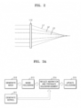
- FIG. 2 is a cross-sectional diagram illustrating an example of aberrations of an optical system 112.
- the holographic display device may have aberrations.
- the aberrations may refer to all optical aberrations that may occur due to wave characteristics of light and/or a holographic display device.
- the aberrations may include spherical aberration, astigmatism, coma, distortion, and/or curvature of field, but the disclosure is not limited thereto.
- focal positions of light L1, light L2, and light L3 diffracted in the optical system 112 may be different.
- a method for compensating for aberrations is required.
- FIG. 3A illustrates a method for generating a hologram by compensating for aberrations of a holographic display device according to an example embodiment.
- the processor may generate kernels.
- the aberration of the holographic display device may not appear uniformly on the hologram plane.
- the hologram plane segments are spatial segments of the hologram plane.
- the processor may generate kernels, which allows the modeling of aberrations respectively corresponding to the hologram plane segments. Zernike polynomials may be used for the modeling of the aberrations.
- the modeling of the aberrations may be performed with high accuracy through spatial division for the modeling.
- the processor may generate masks.
- the processor may generate masks respectively corresponding to the hologram plane segments.
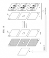
- the processor may mask a hologram. That is, in operation 313, the processor may apply the mask generated in operation 312 to the hologram. According to the masking of the hologram, hologram segments respectively corresponding to the hologram plane segments may be generated. With reference to FIG. 3B , for example, a hologram segment 323 may be generated by filtering a hologram 321 by a mask 322.
- the processor may reflect aberrations and propagate the hologram segment.
- the aberration corresponding to the hologram plane segment may be modeled in the kernel. Accordingly, by propagating the hologram segment using the kernel, the aberration corresponding to the hologram plane segment may be reflected and the hologram segment may be propagated. As the hologram segment is propagated, an image segment may be generated.
- the processor may update a hologram.
- the processor may update the hologram based on a comparison between the image segment and a reference image segment.
- the reference image segment may be a predetermined image segment.
- the reference image segments may be previously stored in a storage, and acquired from the storage while performing the comparison.
- the predetermined image segment may be generated by spatially dividing a predetermined image.
- the predetermined image may be spatially divided same as the hologram plane.
- a loss function may be used for updating a hologram.
- the loss function may be determined from a difference in intensities of the image segment and the predetermined image segment.
- a process of repeating operations 313 to 315 may be performed using an updated hologram to optimize the loss function.
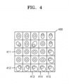
- FIG. 4 illustrates patterns formed on hologram plane segments by aberrations according to an example embodiment.
- a hologram plane 400 may be divided into hologram plane segments.
- FIG. 4 illustrates a case in which the hologram plane 400 is divided into hologram plane segments of a 5x5 array.
- the hologram plane 400 may be divided into various numbers and sizes of hologram plane segments.
- the aberration of the holographic display device may not affect the hologram plane 400 uniformly in spatial terms.
- different patterns may appear in each hologram plane segment.
- the processor may generate kernels in which aberrations respectively corresponding to the hologram plane segments are modeled. For example, the processor may generate a kernel in which aberration corresponding to a hologram plane segment 411 is modeled and a kernel in which aberration corresponding to a hologram plane segment 412 is modeled.
- the processor may perform modeling of aberrations respectively corresponding to the hologram plane segments using Zernike polynomials, and generate kernels based on each Zernike polynomial.
- Equation 1 h i represents a kernel corresponding to the i th hologram plane segment, B(r) represents a function in which a basic wavefront of optical propagation is modeled, r represents a propagation distance, and W i represents a function in which a wavefront due to aberration corresponding to the i th hologram plane segment is modeled.
- B(r) may be modeled as exp(jkr)/r.
- exp refers to exponential.
- W i of the wavefront by aberration may be modeled as the following Equation 2.
- W i exp j ⁇ ⁇ ⁇ j Z j
- Equation 2 ⁇ represents Zernike coefficients, Z represents Zernike polynomials, and j represents indexes of Zernike polynomials.
- the indexes of Zernike polynomials may be determined by various criteria. For example, the OSA/ANSI index, Fringe index, Noll index, Wyant index, etc. may be used as the indexes of Zernike polynomials.
- Table 1 shows various examples of Zernike polynomials according to the OSA/ANSI index.
- ⁇ represents an azimuthal angle
- ⁇ represents a radial distance
- the processor may be configured to determine the indexes and/or coefficients of Zernike polynomials by using a program analyzing aberrations. Alternatively, the processor may generate kernels by obtaining the indexes and/or coefficients of Zernike polynomials from a user input.
- the processor may determine a Zernike coefficient for at least one hologram plane segment by interpolating Zernike coefficients, which have been modeled for neighboring hologram plane segments. For example, the processor may determine a Zernike coefficient of a hologram plane segment 414 by interpolating Zernike coefficients of hologram plane segments 413 and 415 neighboring the hologram plane segment 414. By obtaining Zernike coefficients through interpolation, the calculation time may be reduced. Further, by obtaining Zernike coefficients through interpolation based on spatial adjacency, the accuracy in the aberration modeling may not be diminished.
- FIG. 5A illustrates merge of hologram plane segments according to an example embodiment.
- the processor may generate a merged hologram plane segment by merging multiple hologram plane segments.
- the processor may generate a merged hologram plane segment by merging at least two hologram plane segments.
- the processor may generate a merged hologram plane segment 510 by merging hologram plane segments 511, 512, 513 and 514 having relatively small aberrations.
- the processor may generate a kernel corresponding to the merged hologram plane segment 510.
- hologram plane segments As the number of hologram plane segments increases, more processes may need to be in parallel. By reducing the number of hologram plane segments by merging two or more hologram plane segments, the load of parallel processing may decrease. Further, by merging the hologram plane segments considering the levels of aberrations, the accuracy in the aberration modeling may not be diminished.
- FIG. 5B illustrates division of hologram plane segments according to an embodiment.
- the processor may generate divided hologram segments by dividing a hologram plane segment.
- the processor may generate divided hologram plane segments by dividing at least one hologram plane segment.
- the processor may generate divided hologram plane segments 521, 522, 523 and 524 by dividing a hologram plane segment 520 having relatively large aberration.
- the processor may generate kernels respectively corresponding to the divided hologram plane segments 521, 522, 523 and 524.
- the modeling of the aberrations may be performed with high accuracy through spatial division for the modeling.
- FIG. 6 illustrates masks 621 to 623 according to an example embodiment.
- the processor may generate masks respectively corresponding to the hologram plane segments. For example, the processor may generate the mask 621 corresponding to a hologram plane segment 611 of a hologram plane 600, the mask 622 corresponding to a hologram plane segment 612, and the mask 623 corresponding to a hologram plane segment 613.
- the mask 621 may include a pass area 621a corresponding to a hologram plane segment and a remainder cut-off area 621b.
- the mask 621 may be a binary mask of which the pass area 621a has a pixel value of 1 and the cut-off area 621b has a pixel value of 0, but the disclosure is not limited thereto.
- FIGS. 7A and 7B illustrate masks 710 and 720 for a blurring process according to an example embodiment.
- the mask 710 may be configured to filter a hologram, allowing a hologram segment to have a soft edge.
- the mask 710 may have different pixel values for an edge area 711a of a pass area 711 and a central area 711b of the pass area 711 in an example embodiment.
- the pixel value of the edge area 711a may be 0.8
- the pixel value of the central area 711b may be 1.
- a variety of filtering methods for filtering a hologram which allow a hologram segment to have a soft edge, may be used on the mask 710.
- a boundary line between the image segments may be removed.
- the mask 720 may be configured to filter a hologram, allowing a hologram segment neighboring another hologram segment to have a soft edge.
- the edge area 721b, which adjoins the cut-off area 722 may have a different pixel value than that of a central area 721c, and the edge area 721a, which does not adjoin the cut-off area 722, may have the same pixel value as that of the central area 721c.
- the pixel value of the edge area 721b, which adjoins the cut-off area 722 may be 0.8
- the pixel value of the edge area 721a, which does not adjoin the cut-off area 722, and the central area 721c may be 1.
- FIG. 8 illustrates an optimization loop for generating a hologram by compensating for aberrations of a holographic display device according to an example embodiment.
- the processor may generate N kernels (h i ) and N masks (M i ) corresponding to hologram plane segments. Further, the processor may generate a hologram ( ⁇ ) with randomized phase data and amplitude data.
- the processor may generate N hologram segments (M i ⁇ ) by masking the hologram ( ⁇ ), using the masks (M i ).
- the processor may generate N image segments (f i ) by propagating the hologram segments (M i ⁇ ) to the image plane IP from the hologram plane HP.
- the image segments may be obtained by propagating the hologram segments in parallel.
- the image segments may be obtained by propagating the hologram segments in series.
- the propagation may be performed by a convolution operation of the hologram segments (M i ⁇ ) and the kernels (h i ).
- the hologram segments (M i ⁇ ) As aberrations respectively corresponding to the hologram plane segments are modeled in the kernels (h i ), by propagating the hologram segments (M i ⁇ ) based on the kernels (h i ), the aberrations respectively corresponding to the hologram plane segments may be reflected, and then the hologram segments (M i ⁇ ) may be propagated.
- the processor may update the hologram ( ⁇ ) to optimize a loss function defined by a difference between the image segments (f i ) and reference image segments.
- the reference image segments may be predetermined image segments (P i ).
- the predetermined image segments (P i ) may be obtained by spatially dividing a predetermined image same as the hologram plane HP.
- the predetermined image segments (P i ) may be obtained by masking the predetermined image by using the masks (M i ).
- the loss function may be defined by a difference in intensities of the image segments (f i ) and the predetermined image segments (P i ).
- the loss function may be defined by a root mean square of the difference in intensities of the image segments (f i ) and the predetermined image segments (P i ).
- Equation 3 L represents a loss function, I f i represents an intensity of an image segment, and I P i represents an intensity of a predetermined image segment.
- the hologram ( ⁇ ) may be updated based on the following Equation 4.
- ⁇ ⁇ + b ⁇ L ⁇ ⁇
- Equation 4 b represents an arbitrary constant.
- the kernels (h i ) are formed by using Zernike polynomials, the loss function may be differentiated. Accordingly, the hologram ( ⁇ ) may be updated based on the Equation 4.
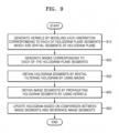
- FIG. 9 illustrates a flowchart of a method for generating a hologram by compensating for aberrations of a holographic display device according to an example embodiment.
- the processor may generate kernels by modeling each aberration corresponding to each of hologram plane segments, which are spatial segments of a hologram plane.
- the processor may generate kernels using Zernike polynomials.
- the processor may merge or divide the hologram plane segments based on a level of aberrations.
- the level of aberrations may be determined from a size of Zernike coefficients.
- the level of aberrations may be determined from the user's visual judgment.
- the processor may generate a kernel corresponding to a merged hologram plane segment and a kernel corresponding to a divided hologram plane segment.
- the processor may generate masks respectively corresponding to the hologram plane segments.
- the mask may include a pass area corresponding to a hologram plane segment and a remainder cut-off area. Further, the mask may be generated where an edge area of the pass area has a different pixel value than that of a central area of the pass area, allowing the hologram segment to have a soft edge.
- the processor may obtain hologram segments by spatial filtering a hologram by using the masks.
- the processor may obtain image segments by propagating the hologram segments by using the kernels.
- the processor may propagate the hologram segment from the hologram plane to the image plane by a convolution operation of the kernels and the hologram segments.
- the hologram segment may be propagated reflecting the aberrations.
- the processor may update the hologram based on a comparison between the image segments and predetermined image segments.
- the processor may determine a loss function based on a difference in intensities of the image segment and the predetermined image segment, and update the hologram to optimize the loss function.
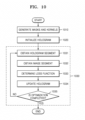
- FIG. 10 illustrates a flowchart of a method for generating a hologram by compensating for aberrations of a holographic display device, including an optimization loop 1030, according to an example embodiment.
- the processor may generate masks and kernels.
- the processor may initialize a hologram.
- the hologram may be initialized to have arbitrary phase data and amplitude data.
- the processor may obtain hologram segments.
- the processor may obtain hologram segments by spatially dividing a hologram by using masks.
- the processor may obtain image segments.
- the processor may obtain the image segments by propagating the hologram segments by using kernels.
- the processor may determine a loss function. For example, the processor may determine a root mean square of a difference in intensities of image segments and predetermined image segments as the loss function.
- the processor may update a hologram.
- the processor may update the hologram to optimize the loss function.
- the processor may determine completion of optimization.
- the processor may determine completion of optimization based on a value of the loss function. According to an example embodiment, the processor may determine completion of optimization when the value of the loss function satisfies a reference value. Alternatively, the processor may determine completion of optimization based on the number of iterations of the optimization loop 1030. According to an example embodiment, the processor may determine completion of optimization when the number of iterations of the optimization loop 1030 satisfies a reference number.
- FIGS. 11A and 11B illustrate the results of an experiment employing a method for generating a hologram by compensating for aberrations of a holographic display device according to an embodiment.
- FIG. 11A illustrates the reference image 1110, a hologram 1120 generated to compensate for aberrations of a holographic display device based on a method according to an example embodiment, and a holographic image 1130 reproduced by the hologram 1120.
- FIG. 11B illustrates a graph of peak-signal ratio (PSNR) of the holographic image 1130 according to the number of iterations of the optimization loop.
- PSNR peak-signal ratio
- the holographic image 1130 of excellent quality hardly having no difference between the reference image 1110 and the holographic image 1130 is obtained. Further, by using hologram segments generated through filtering to have a soft edge, no boundary line has been generated between image segments in the holographic image 1130.
- the quality of the holographic image 1130 may also be supported by the PSNR.
- the example embodiments may also be implemented in the form of a computer-readable recording medium including computer-executable commands, such as a computer module.
- the computer-readable recording medium may be any available medium which can be accessed by a computer, and include volatile and non-volatile media, and separable and non-separable media.
- the computer-readable recording media may include both of computer storage media and communication media.
- the computer storage media may include volatile and non-volatile media, and separable and non-separable media, which are implemented by any method or technology for storing information, such as computer-readable commands, data structures, program modules, or other data.
- the communication media may typically include other data of modulated data signals, such as computer-readable commands, data structures, program modules, or other transmission mechanisms, and also include any information delivery media.
- a "unit” may refer to a hardware component, such as a processor or a circuit, and/or a software component executed by a hardware component, such as a processor.
Landscapes
- Physics & Mathematics (AREA)
- General Physics & Mathematics (AREA)
- Engineering & Computer Science (AREA)
- Theoretical Computer Science (AREA)
- Computing Systems (AREA)
- Holo Graphy (AREA)
- Optical Recording Or Reproduction (AREA)
- Geometry (AREA)
Claims (14)
- Verfahren zur Kompensation von Aberrationen einer holographischen Anzeigevorrichtung bei der Erzeugung eines Hologramms zur Wiedergabe eines holographischen Bildes, wobei das Verfahren Folgendes umfasst:Initialisieren (1020) eines computererzeugten Hologramms;Erzeugen (920, 1010) von Masken, die Hologrammebenensegmenten einer Hologrammebene entsprechen;Erhalten (930, 1031) von Hologrammsegmenten durch räumliches Filtern des computererzeugten Hologramms unter Verwendung der Masken;Erzeugen (910, 1010) eines Kerns für jedes Hologrammebenensegment durch Modellieren von diesem Hologrammebenensegment entsprechenden Aberrationen;Erhalten (940, 1032) von ersten Bildsegmenten durch Ausbreiten jedes Hologrammsegments unter Verwendung des entsprechenden Kerns; undAktualisieren (950, 1034) des Hologramms basierend auf einem Vergleich zwischen den ersten Bildsegmenten und Referenzbildsegmenten, die aus einem Speicher erhalten werden, entsprechend dem zu reproduzierenden holografischen Bild.
- Verfahren nach Anspruch 1, wobei es sich bei den Hologrammebenensegmenten um räumliche Segmente der Hologrammebene handelt.
- Verfahren nach Anspruch 1, wobei das Erzeugen (910, 1010) der Kerne Folgendes umfasst:Modellieren der Aberrationen, die den Hologrammebenensegmenten entsprechen, unter Verwendung von Zernike-Polynomen; undErzeugen jedes der Kerne basierend auf jedem der Zernike-Polynome.
- Verfahren nach Anspruch 3, wobei das Modellieren der Aberrationen, die den Hologrammebenensegmenten entsprechen, unter Verwendung jedes der Zernike-Polynome, das Bestimmen von Zernike-Koeffizienten für zumindest ein Hologrammebenensegment unter den Hologrammebenensegmenten umfasst, indem Zernike-Koeffizienten, die für benachbarte Hologrammebenensegmente unter den Hologrammebenensegmenten modelliert wurden, interpoliert werden.
- Verfahren nach Anspruch 1,wobei das Erzeugen (910, 1010) der Kerne Folgendes umfasst:Erzeugen von geteilten Hologrammebenensegmenten durch Teilen zumindest eines Hologrammebenensegments unter den Hologrammebenensegmenten; undErzeugen der Kerne basierend auf den geteilten Hologrammebenensegmenten,oder wobei das Erzeugen (910, 1010) der Kerne Folgendes umfasst:Erzeugen eines verschmolzenen Hologrammebenensegments durch Verschmelzen von zumindest zwei Hologrammebenensegmenten unter den Hologrammebenensegmenten; undErzeugen eines Kerns, unter den Kernen, basierend auf dem verschmolzenen Hologrammebenensegment.
- Verfahren nach Anspruch 1, wobei das Erzeugen (920, 1010) der Masken das Erzeugen zumindest einer Maske umfasst, die einen Durchgangsbereich, der einem jeweiligen Hologrammebenensegment entspricht, und einen verbleibenden Grenzbereich enthält.
- Verfahren nach Anspruch 6, wobei das Erzeugen der Masken (920, 1010) ferner das Erzeugen zumindest einer Maske umfasst, bei der ein Kantenbereich des Durchgangsbereichs einen anderen Pixelwert aufweist als ein zentraler Bereich des Durchgangsbereichs, oder wobei das Erzeugen der Masken (920, 1010) ferner Folgendes umfasst: Erzeugen zumindest einer Maske, bei der ein erster Kantenbereich des Durchgangsbereichs, der an den Grenzbereich angrenzt, einen anderen Pixelwert aufweist als ein zentraler Bereich des Durchgangsbereichs, und ein zweiter Kantenbereich des Durchgangsbereichs, der nicht an den Grenzbereich angrenzt, einen gleichen Pixelwert aufweist wie der zentrale Bereich des Durchgangsbereichs.
- Verfahren nach Anspruch 1, wobei das Erhalten (940, 1032) der ersten Bildsegmente das Erhalten der ersten Bildsegmente durch paralleles Ausbreiten der Hologrammsegmente umfasst.
- Verfahren nach Anspruch 1, wobei das Aktualisieren (950, 1034) des Hologramms Folgendes umfasst:Bestimmen einer Verlustfunktion basierend auf einer Differenz der Intensitäten der ersten Bildsegmente und der Referenzbildsegmente; undAktualisieren des Hologramms zur Optimierung der Verlustfunktion.
- Übergangsloses computerlesbares Aufzeichnungsmedium, auf dem ein Computerprogramm zur Ausführung des Verfahrens nach einem der vorhergehenden Ansprüche auf einem Computer gespeichert ist.
- Holografische Anzeigevorrichtung (100), die Folgendes umfasst:eine Lichtquelle (111), die zum Emittieren von Licht konfiguriert ist, um ein holografisches Bild zu reproduzieren;ein optisches System (112), das konfiguriert ist, um das holographische Bild räumlich zu fokussieren;einen Prozessor (121), der konfiguriert ist, um Aberrationen der holografischen Anzeigevorrichtung bei der Erzeugung eines computergenerierten Hologramms zu kompensieren, um das holografische Bild zu reproduzieren; undeinen räumlichen Lichtmodulator (113), der konfiguriert ist, um das Licht basierend auf dem Hologramm zu modulieren,wobei der Prozessor (121) zu Folgendem konfiguriert ist:Initialisieren eines computererzeugten Hologramms;Erzeugen von Masken, die Hologrammebenensegmenten einer Hologrammebene entsprechen;Erhalten von Hologrammsegmenten durch räumliches Filtern des computererzeugten Hologramms unter Verwendung der Masken;Erzeugen eines Kerns für jedes Hologrammebenensegment durch Modellieren von jeder diesem Hologrammebenensegment entsprechenden Aberration;Erhalten von ersten Bildsegmenten durch Ausbreiten jedes Hologrammsegments unter Verwendung des entsprechenden Kerns; undAktualisieren des Hologramms basierend auf einem Vergleich zwischen den ersten Bildsegmenten und Referenzbildsegmenten, die aus einem Speicher erhalten werden, der dem zu reproduzierenden holografischen Bild entspricht.
- Holographisches Anzeigesystem (100) nach Anspruch 11, wobei der Prozessor (121) ferner konfiguriert ist, um die Modellierung der den Hologrammebenensegmenten entsprechenden Aberrationen unter Verwendung von Zernike-Polynomen durchzuführen und jeden der Kerne basierend auf jedem der Zernike-Polynome zu erzeugen.
- Holographisches Anzeigesystem (100) nach Anspruch 12, wobei der Prozessor (121) ferner konfiguriert ist, um Zernike-Koeffizienten für zumindest ein Hologrammebenensegment unter den Hologrammebenensegmenten zu bestimmen, indem Zernike-Koeffizienten, die für benachbarte Hologrammebenensegmente unter den Hologrammebenensegmenten modelliert wurden, interpoliert werden.
- Holographisches Anzeigesystem (100) nach Anspruch 11,
wobei der Prozessor (121) ferner konfiguriert ist, um geteilte Hologrammebenensegmente zu erzeugen durch Teilen zumindest eines Hologrammebenensegments unter den Hologrammebenensegmenten und Erzeugen der Kerne basierend auf den geteilten Hologrammebenensegmenten, oder- wobei der Prozessor (121) ferner konfiguriert ist, um ein verschmolzenes Hologrammebenensegment zu erzeugen durch Verschmelzen von zumindest zwei Hologrammebenensegmenten unter den Hologrammebenensegmenten, und einen Kern unter den Kernen basierend auf dem verschmolzenen Hologrammebenensegment unter den Hologrammebenensegmenten zu erzeugen, oder- wobei der Prozessor (121) ferner konfiguriert ist, um zumindest eine Maske zu erzeugen, die einen Durchgangsbereich, der einem jeweiligen Hologrammebenensegment entspricht, und einen verbleibenden Grenzbereich enthält, wobei in einer bevorzugten Ausführungsform der Prozessor ferner konfiguriert ist, um zumindest eine Maske zu erzeugen, bei der ein Kantenbereich des Durchgangsbereichs einen anderen Pixelwert aufweist als ein zentraler Bereich des Durchgangsbereichs,- wobei der Prozessor (121) konfiguriert ist, um die ersten Bildsegmente durch paralleles Ausbreiten der Hologrammsegmente zu erhalten, oder- wobei der Prozessor (121) ferner konfiguriert ist, um eine Verlustfunktion basierend auf einer Differenz der Intensitäten der ersten Bildsegmente und der Referenzbildsegmente zu bestimmen und das Hologramm zu aktualisieren, um die Verlustfunktion zu optimieren.
Applications Claiming Priority (1)
| Application Number | Priority Date | Filing Date | Title |
|---|---|---|---|
| KR1020210036806A KR102892299B1 (ko) | 2021-03-22 | 2021-03-22 | 홀로그래픽 디스플레이 장치의 수차를 보상하여 홀로그램을 생성하기 위한 방법 및 홀로그래픽 디스플레이 시스템 |
Publications (2)
| Publication Number | Publication Date |
|---|---|
| EP4063972A1 EP4063972A1 (de) | 2022-09-28 |
| EP4063972B1 true EP4063972B1 (de) | 2025-04-23 |
Family
ID=79164950
Family Applications (1)
| Application Number | Title | Priority Date | Filing Date |
|---|---|---|---|
| EP21218405.5A Active EP4063972B1 (de) | 2021-03-22 | 2021-12-30 | Holographisches anzeigesystem und verfahren zur erzeugung eines hologramms durch kompensation der aberration einer holographischen anzeigevorrichtung |
Country Status (5)
| Country | Link |
|---|---|
| US (1) | US12314008B2 (de) |
| EP (1) | EP4063972B1 (de) |
| JP (1) | JP2022146929A (de) |
| KR (1) | KR102892299B1 (de) |
| CN (1) | CN115128929A (de) |
Families Citing this family (3)
| Publication number | Priority date | Publication date | Assignee | Title |
|---|---|---|---|---|
| KR102903272B1 (ko) | 2021-03-30 | 2025-12-22 | 삼성전자주식회사 | 홀로그램을 생성하는 방법 및 홀로그래픽 디스플레이 시스템 |
| KR20230082435A (ko) | 2021-12-01 | 2023-06-08 | 삼성전자주식회사 | 도파관형 디스플레이 장치 |
| GB2630118B (en) * | 2023-05-18 | 2025-05-07 | Envisics Ltd | Hologram processing |
Family Cites Families (13)
| Publication number | Priority date | Publication date | Assignee | Title |
|---|---|---|---|---|
| JP4463567B2 (ja) * | 2004-01-06 | 2010-05-19 | 浜松ホトニクス株式会社 | 三次元像表示装置および三次元像表示方法 |
| DE102004063838A1 (de) | 2004-12-23 | 2006-07-06 | Seereal Technologies Gmbh | Verfahren und Einrichtung zum Berechnen computer generierter Videohologramme |
| DE102006036255B4 (de) * | 2006-08-03 | 2013-01-31 | Seereal Technologies S.A. | Verfahren und Vorrichtung zum Auslesen von in Lichtmodulatoren kodierten Informationen |
| KR100910642B1 (ko) | 2007-07-27 | 2009-08-05 | 광운대학교 산학협력단 | 홀로그래피 기법에 의해 획득된 영상의 3차원 집적 영상복원 방법 및 장치 |
| WO2009109785A2 (en) * | 2008-03-07 | 2009-09-11 | Javid Khan | A three dimensional holographic volumetric display |
| KR101926547B1 (ko) * | 2011-10-28 | 2018-12-10 | 삼성전자주식회사 | 고속으로 3d 홀로그램을 생성하는 방법 및 장치 |
| US20140268277A1 (en) | 2013-03-14 | 2014-09-18 | Andreas Georgiou | Image correction using reconfigurable phase mask |
| US9865089B2 (en) * | 2014-07-25 | 2018-01-09 | Microsoft Technology Licensing, Llc | Virtual reality environment with real world objects |
| KR101800929B1 (ko) * | 2015-01-29 | 2017-11-23 | 한국전자통신연구원 | 홀로그래픽 디스플레이 왜곡 보정 방법 및 장치 |
| US10379494B2 (en) * | 2016-08-10 | 2019-08-13 | Disney Enterprises, Inc. | Scanned coarse integral holographic display having holographic lenslets displayed by spatial light modulator |
| KR102497832B1 (ko) | 2017-12-26 | 2023-02-08 | 한국전자통신연구원 | 홀로그램 생성 장치 및 그 방법 |
| US11068052B2 (en) | 2019-03-15 | 2021-07-20 | Microsoft Technology Licensing, Llc | Holographic image generated based on eye position |
| US11875255B2 (en) * | 2019-08-26 | 2024-01-16 | Samsung Electronics Co., Ltd. | Method and apparatus for processing data |
-
2021
- 2021-03-22 KR KR1020210036806A patent/KR102892299B1/ko active Active
- 2021-10-27 CN CN202111256649.6A patent/CN115128929A/zh active Pending
- 2021-11-29 US US17/536,511 patent/US12314008B2/en active Active
- 2021-12-30 EP EP21218405.5A patent/EP4063972B1/de active Active
-
2022
- 2022-03-18 JP JP2022044068A patent/JP2022146929A/ja active Pending
Also Published As
| Publication number | Publication date |
|---|---|
| US12314008B2 (en) | 2025-05-27 |
| CN115128929A (zh) | 2022-09-30 |
| US20220299939A1 (en) | 2022-09-22 |
| KR102892299B1 (ko) | 2025-11-26 |
| KR20220131741A (ko) | 2022-09-29 |
| EP4063972A1 (de) | 2022-09-28 |
| JP2022146929A (ja) | 2022-10-05 |
Similar Documents
| Publication | Publication Date | Title |
|---|---|---|
| KR102047544B1 (ko) | 디스플레이 시스템 | |
| US12314008B2 (en) | Holographic display system and method for generating hologram by compensating for aberration of holographic display device | |
| KR102919919B1 (ko) | 이미지 투사 | |
| US8482828B2 (en) | Holographic imaging display with corrected phase coding | |
| US20230171385A1 (en) | Methods, systems, and computer readable media for hardware-in-the-loop phase retrieval for holographic near eye displays | |
| KR102939383B1 (ko) | 광학 측정 방법 및 광학 측정 시스템 | |
| US12619070B2 (en) | Hologram waveguiding | |
| US12025952B2 (en) | Holographic display system and method of generating hologram | |
| JP4936959B2 (ja) | ホログラム情報記録再生方法、ならびにホログラム情報記録再生装置、ホログラム情報記録装置、およびホログラム情報再生装置 | |
| EP1876591A2 (de) | Hologrammaufzeichnungsvorrichtung, Hologrammwiedergabevorrichtung und Hologrammaufzeichnungsverfahren ohne Erfordernis der Positionierung einer Phasenmaske | |
| Zimmermann et al. | Improved far-field holograms using spatial light modulators and camera-in-the-loop optimization | |
| CN116819771A (zh) | 一种全息三维光学显示系统 | |
| Lin et al. | Optical in-line holographic three-dimensional video display with omnidirectional viewing zones based on a center-symmetric multi-sideband filtering method | |
| Yamaguchi et al. | Development of a Fringe Printer With 0.35 μm Pixel Pitch | |
| Zimmermann et al. | Impact of aberrations in SLM-based far-field holography | |
| KR20210070719A (ko) | 투과형 위상 마스크를 이용하여 시야각을 확장한 홀로그래픽 디스플레이 장치 및 방법 | |
| US20250139735A1 (en) | Hologram calculation method | |
| US11768462B2 (en) | Systems and methods for an integrated holographic reconstruction tool with optical distortion removal and de-twinning | |
| US20250116966A1 (en) | Hologram calculation method | |
| Starobrat et al. | Randomisation of undersampled pixels for image duplicate suppression in holographic projection | |
| Kerov et al. | Binary hologram generation by adapting the structural similarity index measure | |
| Matsushima | Computer Holography | |
| JPS624681B2 (de) | ||
| KR20250128132A (ko) | 홀로그램 재현 영상 dc 노이즈 필터 설계 장치 및 방법 | |
| TW202509618A (zh) | 孔徑遮罩 |
Legal Events
| Date | Code | Title | Description |
|---|---|---|---|
| PUAI | Public reference made under article 153(3) epc to a published international application that has entered the european phase |
Free format text: ORIGINAL CODE: 0009012 |
|
| STAA | Information on the status of an ep patent application or granted ep patent |
Free format text: STATUS: THE APPLICATION HAS BEEN PUBLISHED |
|
| AK | Designated contracting states |
Kind code of ref document: A1 Designated state(s): AL AT BE BG CH CY CZ DE DK EE ES FI FR GB GR HR HU IE IS IT LI LT LU LV MC MK MT NL NO PL PT RO RS SE SI SK SM TR |
|
| STAA | Information on the status of an ep patent application or granted ep patent |
Free format text: STATUS: REQUEST FOR EXAMINATION WAS MADE |
|
| 17P | Request for examination filed |
Effective date: 20230323 |
|
| RBV | Designated contracting states (corrected) |
Designated state(s): AL AT BE BG CH CY CZ DE DK EE ES FI FR GB GR HR HU IE IS IT LI LT LU LV MC MK MT NL NO PL PT RO RS SE SI SK SM TR |
|
| P01 | Opt-out of the competence of the unified patent court (upc) registered |
Effective date: 20230530 |
|
| GRAP | Despatch of communication of intention to grant a patent |
Free format text: ORIGINAL CODE: EPIDOSNIGR1 |
|
| STAA | Information on the status of an ep patent application or granted ep patent |
Free format text: STATUS: GRANT OF PATENT IS INTENDED |
|
| GRAS | Grant fee paid |
Free format text: ORIGINAL CODE: EPIDOSNIGR3 |
|
| GRAA | (expected) grant |
Free format text: ORIGINAL CODE: 0009210 |
|
| STAA | Information on the status of an ep patent application or granted ep patent |
Free format text: STATUS: THE PATENT HAS BEEN GRANTED |
|
| INTG | Intention to grant announced |
Effective date: 20250220 |
|
| AK | Designated contracting states |
Kind code of ref document: B1 Designated state(s): AL AT BE BG CH CY CZ DE DK EE ES FI FR GB GR HR HU IE IS IT LI LT LU LV MC MK MT NL NO PL PT RO RS SE SI SK SM TR |
|
| REG | Reference to a national code |
Ref country code: GB Ref legal event code: FG4D |
|
| REG | Reference to a national code |
Ref country code: CH Ref legal event code: EP |
|
| REG | Reference to a national code |
Ref country code: DE Ref legal event code: R096 Ref document number: 602021029547 Country of ref document: DE |
|
| REG | Reference to a national code |
Ref country code: IE Ref legal event code: FG4D |
|
| REG | Reference to a national code |
Ref country code: NL Ref legal event code: MP Effective date: 20250423 |
|
| PG25 | Lapsed in a contracting state [announced via postgrant information from national office to epo] |
Ref country code: NL Free format text: LAPSE BECAUSE OF FAILURE TO SUBMIT A TRANSLATION OF THE DESCRIPTION OR TO PAY THE FEE WITHIN THE PRESCRIBED TIME-LIMIT Effective date: 20250423 |
|
| REG | Reference to a national code |
Ref country code: AT Ref legal event code: MK05 Ref document number: 1788332 Country of ref document: AT Kind code of ref document: T Effective date: 20250423 |
|
| PG25 | Lapsed in a contracting state [announced via postgrant information from national office to epo] |
Ref country code: ES Free format text: LAPSE BECAUSE OF FAILURE TO SUBMIT A TRANSLATION OF THE DESCRIPTION OR TO PAY THE FEE WITHIN THE PRESCRIBED TIME-LIMIT Effective date: 20250423 Ref country code: FI Free format text: LAPSE BECAUSE OF FAILURE TO SUBMIT A TRANSLATION OF THE DESCRIPTION OR TO PAY THE FEE WITHIN THE PRESCRIBED TIME-LIMIT Effective date: 20250423 Ref country code: PT Free format text: LAPSE BECAUSE OF FAILURE TO SUBMIT A TRANSLATION OF THE DESCRIPTION OR TO PAY THE FEE WITHIN THE PRESCRIBED TIME-LIMIT Effective date: 20250825 |
|
| REG | Reference to a national code |
Ref country code: LT Ref legal event code: MG9D |
|
| PG25 | Lapsed in a contracting state [announced via postgrant information from national office to epo] |
Ref country code: GR Free format text: LAPSE BECAUSE OF FAILURE TO SUBMIT A TRANSLATION OF THE DESCRIPTION OR TO PAY THE FEE WITHIN THE PRESCRIBED TIME-LIMIT Effective date: 20250724 Ref country code: NO Free format text: LAPSE BECAUSE OF FAILURE TO SUBMIT A TRANSLATION OF THE DESCRIPTION OR TO PAY THE FEE WITHIN THE PRESCRIBED TIME-LIMIT Effective date: 20250723 |
|
| PG25 | Lapsed in a contracting state [announced via postgrant information from national office to epo] |
Ref country code: PL Free format text: LAPSE BECAUSE OF FAILURE TO SUBMIT A TRANSLATION OF THE DESCRIPTION OR TO PAY THE FEE WITHIN THE PRESCRIBED TIME-LIMIT Effective date: 20250423 |
|
| PG25 | Lapsed in a contracting state [announced via postgrant information from national office to epo] |
Ref country code: BG Free format text: LAPSE BECAUSE OF FAILURE TO SUBMIT A TRANSLATION OF THE DESCRIPTION OR TO PAY THE FEE WITHIN THE PRESCRIBED TIME-LIMIT Effective date: 20250423 |
|
| PG25 | Lapsed in a contracting state [announced via postgrant information from national office to epo] |
Ref country code: HR Free format text: LAPSE BECAUSE OF FAILURE TO SUBMIT A TRANSLATION OF THE DESCRIPTION OR TO PAY THE FEE WITHIN THE PRESCRIBED TIME-LIMIT Effective date: 20250423 |
|
| PG25 | Lapsed in a contracting state [announced via postgrant information from national office to epo] |
Ref country code: AT Free format text: LAPSE BECAUSE OF FAILURE TO SUBMIT A TRANSLATION OF THE DESCRIPTION OR TO PAY THE FEE WITHIN THE PRESCRIBED TIME-LIMIT Effective date: 20250423 |
|
| PG25 | Lapsed in a contracting state [announced via postgrant information from national office to epo] |
Ref country code: RS Free format text: LAPSE BECAUSE OF FAILURE TO SUBMIT A TRANSLATION OF THE DESCRIPTION OR TO PAY THE FEE WITHIN THE PRESCRIBED TIME-LIMIT Effective date: 20250723 |
|
| PG25 | Lapsed in a contracting state [announced via postgrant information from national office to epo] |
Ref country code: IS Free format text: LAPSE BECAUSE OF FAILURE TO SUBMIT A TRANSLATION OF THE DESCRIPTION OR TO PAY THE FEE WITHIN THE PRESCRIBED TIME-LIMIT Effective date: 20250823 |
|
| PG25 | Lapsed in a contracting state [announced via postgrant information from national office to epo] |
Ref country code: LV Free format text: LAPSE BECAUSE OF FAILURE TO SUBMIT A TRANSLATION OF THE DESCRIPTION OR TO PAY THE FEE WITHIN THE PRESCRIBED TIME-LIMIT Effective date: 20250423 |
|
| PGFP | Annual fee paid to national office [announced via postgrant information from national office to epo] |
Ref country code: DE Payment date: 20251111 Year of fee payment: 5 |
|
| PGFP | Annual fee paid to national office [announced via postgrant information from national office to epo] |
Ref country code: GB Payment date: 20251113 Year of fee payment: 5 |
|
| PG25 | Lapsed in a contracting state [announced via postgrant information from national office to epo] |
Ref country code: SM Free format text: LAPSE BECAUSE OF FAILURE TO SUBMIT A TRANSLATION OF THE DESCRIPTION OR TO PAY THE FEE WITHIN THE PRESCRIBED TIME-LIMIT Effective date: 20250423 Ref country code: DK Free format text: LAPSE BECAUSE OF FAILURE TO SUBMIT A TRANSLATION OF THE DESCRIPTION OR TO PAY THE FEE WITHIN THE PRESCRIBED TIME-LIMIT Effective date: 20250423 |
|
| PGFP | Annual fee paid to national office [announced via postgrant information from national office to epo] |
Ref country code: FR Payment date: 20251124 Year of fee payment: 5 |
|
| PG25 | Lapsed in a contracting state [announced via postgrant information from national office to epo] |
Ref country code: CZ Free format text: LAPSE BECAUSE OF FAILURE TO SUBMIT A TRANSLATION OF THE DESCRIPTION OR TO PAY THE FEE WITHIN THE PRESCRIBED TIME-LIMIT Effective date: 20250423 |
|
| PG25 | Lapsed in a contracting state [announced via postgrant information from national office to epo] |
Ref country code: EE Free format text: LAPSE BECAUSE OF FAILURE TO SUBMIT A TRANSLATION OF THE DESCRIPTION OR TO PAY THE FEE WITHIN THE PRESCRIBED TIME-LIMIT Effective date: 20250423 |
|
| REG | Reference to a national code |
Ref country code: DE Ref legal event code: R097 Ref document number: 602021029547 Country of ref document: DE |
|
| PG25 | Lapsed in a contracting state [announced via postgrant information from national office to epo] |
Ref country code: SK Free format text: LAPSE BECAUSE OF FAILURE TO SUBMIT A TRANSLATION OF THE DESCRIPTION OR TO PAY THE FEE WITHIN THE PRESCRIBED TIME-LIMIT Effective date: 20250423 |
|
| PG25 | Lapsed in a contracting state [announced via postgrant information from national office to epo] |
Ref country code: IT Free format text: LAPSE BECAUSE OF FAILURE TO SUBMIT A TRANSLATION OF THE DESCRIPTION OR TO PAY THE FEE WITHIN THE PRESCRIBED TIME-LIMIT Effective date: 20250423 |
|
| PG25 | Lapsed in a contracting state [announced via postgrant information from national office to epo] |
Ref country code: RO Free format text: LAPSE BECAUSE OF FAILURE TO SUBMIT A TRANSLATION OF THE DESCRIPTION OR TO PAY THE FEE WITHIN THE PRESCRIBED TIME-LIMIT Effective date: 20250423 |
|
| PLBE | No opposition filed within time limit |
Free format text: ORIGINAL CODE: 0009261 |
|
| STAA | Information on the status of an ep patent application or granted ep patent |
Free format text: STATUS: NO OPPOSITION FILED WITHIN TIME LIMIT |
|
| REG | Reference to a national code |
Ref country code: CH Ref legal event code: L10 Free format text: ST27 STATUS EVENT CODE: U-0-0-L10-L00 (AS PROVIDED BY THE NATIONAL OFFICE) Effective date: 20260304 |
|
| 26N | No opposition filed |
Effective date: 20260126 |