EP4063810A1 - Wireless energy-harvesting sensor probe utilizing beam steering for in-oven power stealing - Google Patents
Wireless energy-harvesting sensor probe utilizing beam steering for in-oven power stealing Download PDFInfo
- Publication number
- EP4063810A1 EP4063810A1 EP21163968.7A EP21163968A EP4063810A1 EP 4063810 A1 EP4063810 A1 EP 4063810A1 EP 21163968 A EP21163968 A EP 21163968A EP 4063810 A1 EP4063810 A1 EP 4063810A1
- Authority
- EP
- European Patent Office
- Prior art keywords
- energy emitting
- antenna
- sensor probe
- emitting antennas
- oven
- Prior art date
- Legal status (The legal status is an assumption and is not a legal conclusion. Google has not performed a legal analysis and makes no representation as to the accuracy of the status listed.)
- Pending
Links
Images


Classifications
-
- G—PHYSICS
- G01—MEASURING; TESTING
- G01K—MEASURING TEMPERATURE; MEASURING QUANTITY OF HEAT; THERMALLY-SENSITIVE ELEMENTS NOT OTHERWISE PROVIDED FOR
- G01K1/00—Details of thermometers not specially adapted for particular types of thermometer
- G01K1/02—Means for indicating or recording specially adapted for thermometers
- G01K1/024—Means for indicating or recording specially adapted for thermometers for remote indication
-
- H—ELECTRICITY
- H02—GENERATION; CONVERSION OR DISTRIBUTION OF ELECTRIC POWER
- H02J—CIRCUIT ARRANGEMENTS OR SYSTEMS FOR SUPPLYING OR DISTRIBUTING ELECTRIC POWER; SYSTEMS FOR STORING ELECTRIC ENERGY
- H02J50/00—Circuit arrangements or systems for wireless supply or distribution of electric power
- H02J50/40—Circuit arrangements or systems for wireless supply or distribution of electric power using two or more transmitting or receiving devices
-
- F—MECHANICAL ENGINEERING; LIGHTING; HEATING; WEAPONS; BLASTING
- F24—HEATING; RANGES; VENTILATING
- F24C—DOMESTIC STOVES OR RANGES ; DETAILS OF DOMESTIC STOVES OR RANGES, OF GENERAL APPLICATION
- F24C7/00—Stoves or ranges heated by electric energy
- F24C7/08—Arrangement or mounting of control or safety devices
- F24C7/082—Arrangement or mounting of control or safety devices on ranges, e.g. control panels, illumination
- F24C7/085—Arrangement or mounting of control or safety devices on ranges, e.g. control panels, illumination on baking ovens
-
- H—ELECTRICITY
- H02—GENERATION; CONVERSION OR DISTRIBUTION OF ELECTRIC POWER
- H02J—CIRCUIT ARRANGEMENTS OR SYSTEMS FOR SUPPLYING OR DISTRIBUTING ELECTRIC POWER; SYSTEMS FOR STORING ELECTRIC ENERGY
- H02J50/00—Circuit arrangements or systems for wireless supply or distribution of electric power
- H02J50/001—Energy harvesting or scavenging
-
- H—ELECTRICITY
- H02—GENERATION; CONVERSION OR DISTRIBUTION OF ELECTRIC POWER
- H02J—CIRCUIT ARRANGEMENTS OR SYSTEMS FOR SUPPLYING OR DISTRIBUTING ELECTRIC POWER; SYSTEMS FOR STORING ELECTRIC ENERGY
- H02J50/00—Circuit arrangements or systems for wireless supply or distribution of electric power
- H02J50/20—Circuit arrangements or systems for wireless supply or distribution of electric power using microwaves or radio frequency waves
-
- H—ELECTRICITY
- H02—GENERATION; CONVERSION OR DISTRIBUTION OF ELECTRIC POWER
- H02J—CIRCUIT ARRANGEMENTS OR SYSTEMS FOR SUPPLYING OR DISTRIBUTING ELECTRIC POWER; SYSTEMS FOR STORING ELECTRIC ENERGY
- H02J50/00—Circuit arrangements or systems for wireless supply or distribution of electric power
- H02J50/80—Circuit arrangements or systems for wireless supply or distribution of electric power involving the exchange of data, concerning supply or distribution of electric power, between transmitting devices and receiving devices
-
- H—ELECTRICITY
- H04—ELECTRIC COMMUNICATION TECHNIQUE
- H04B—TRANSMISSION
- H04B1/00—Details of transmission systems, not covered by a single one of groups H04B3/00 - H04B13/00; Details of transmission systems not characterised by the medium used for transmission
- H04B1/38—Transceivers, i.e. devices in which transmitter and receiver form a structural unit and in which at least one part is used for functions of transmitting and receiving
-
- H—ELECTRICITY
- H04—ELECTRIC COMMUNICATION TECHNIQUE
- H04W—WIRELESS COMMUNICATION NETWORKS
- H04W16/00—Network planning, e.g. coverage or traffic planning tools; Network deployment, e.g. resource partitioning or cells structures
- H04W16/24—Cell structures
- H04W16/28—Cell structures using beam steering
-
- G—PHYSICS
- G01—MEASURING; TESTING
- G01K—MEASURING TEMPERATURE; MEASURING QUANTITY OF HEAT; THERMALLY-SENSITIVE ELEMENTS NOT OTHERWISE PROVIDED FOR
- G01K2207/00—Application of thermometers in household appliances
- G01K2207/02—Application of thermometers in household appliances for measuring food temperature
- G01K2207/06—Application of thermometers in household appliances for measuring food temperature for preparation purposes
-
- G—PHYSICS
- G01—MEASURING; TESTING
- G01K—MEASURING TEMPERATURE; MEASURING QUANTITY OF HEAT; THERMALLY-SENSITIVE ELEMENTS NOT OTHERWISE PROVIDED FOR
- G01K2215/00—Details concerning sensor power supply
Definitions
- the present invention is directed to a wireless sensor probe for monitoring temperature which utilizes beam steering for power stealing.
- the invention is directed to a wireless energy-harvesting sensor probe and system which utilizes beam steering for in-oven power stealing.
- a wireless, battery-free meat probe eliminates the hassles of dealing with long wires and having to charge batteries, thereby improving usability and longevity of the product.
- many reflections and refractions combine to create a pattern of 'hotspots' where the field strength is relatively high and deep 'cold spots' where nearly no signal exists, making communications with a wireless, battery-free meat probe difficult.
- An object is to provide a wireless energy-harvesting sensor probe or meat probe which can survive in a high temperature of operation inside an oven.
- An object is to provide a beam steering for stealing which optimizes power directed to a sensor probe.
- An embodiment is directed to a system for measuring the temperature of food in an oven.
- the system includes multiple energy emitting antennas positioned in the oven proximate an oven cavity or, optionally an individual communication antenna with different operation frequency band.
- the multiple energy emitting antennas send signals at the same frequency which are phase shifted relative to each other.
- the system includes a battery-free sensor probe which is configured to be inserted into the food in the oven cavity.
- the battery-free sensor probe has at least an antenna to harvest energy transmitted from the multiple energy emitting antennas.
- the harvested power can be used to power a separate electronic subsystem which can include a wireless data link operating independently.
- the same antenna or another communication antenna with different operation frequency band used to collect power can be used to transmit signals back to the energy emitting antennas.
- the phase shifted signals sent by the multiple energy emitting antennas steer the signals sent by the multiple energy emitting antennas to ensure that the signals sent by the multiple energy emitting antennas are received with maximum link efficiency by the antenna of the battery-free sensor probe.
- An embodiment is directed to a system for measuring the temperature of food in an oven.
- the system includes multiple energy emitting antennas and at least one battery-free sensor probe.
- the multiple energy emitting antennas are positioned in the oven proximate an oven cavity.
- the multiple energy emitting antennas have power transmitters and, optionally, data receivers/transceivers.
- the multiple energy emitting antennas send signals at the same frequency which are phase shifted relative to each other.
- the battery-free sensor probe is configured to be inserted into the food in the oven cavity.
- the battery-free sensor probe has an antenna with a power stealing regulator and a data transmitter/transceiver to harvest energy transmitted from the multiple energy emitting antennas and to transmit signals back to the multiple energy emitting antennas.
- an individual communication antenna with different operation frequency band may be used.
- the phase shifted signals sent by the multiple energy emitting antennas steer the signals sent by the multiple energy emitting antennas to ensure that the signals sent by the multiple energy emitting antennas are received with maximum link efficiency by the antenna of the battery-free sensor probe.
- An embodiment is directed to a system for measuring the temperature of food in an oven.
- the system includes multiple energy emitting antennas, at least one battery-free sensor probe and a feedback loop.
- the multiple energy emitting antennas are positioned in the oven proximate an oven cavity.
- the multiple energy emitting antennas have power transmitters and, optionally, data receivers/transceivers.
- the multiple energy emitting antennas send signals at the same frequency which are phase shifted relative to each other.
- the battery-free sensor probe is configured to be inserted into the food in the oven cavity.
- the battery-free sensor probe has an antenna with a power stealing regulator and a data transmitter/transceiver to harvest energy transmitted from the multiple energy emitting antennas and to transmit signals back to the multiple energy emitting antennas.
- an individual communication antenna with different operation frequency band may be used.
- the feedback loop informs the reader about the quality of the coupling between the power transmitters in the multiple energy emitting antennas and the power stealing regulator in the sensor probe.
- the information about the link quality allows the system to optimize link performance.
- the phase shifted signals sent by the power transmitters in the multiple energy emitting antennas project energy emissions in a search pattern to initially activate the power stealing regulator in the sensor probe to ensure that the signals sent by the multiple energy emitting antennas are received with maximum link efficiency by the antenna of the battery-free sensor probe.
- a sensor probe 10 has a needle or probe portion 12 and a handle 14.
- the needle or probe portion 12 is configured to be inserted or partially inserted into a substance or material, such as, but not limited to meat.
- the handle 14 is configured to be positioned outside or partially outside of the substance or material.
- the probe portion 12 houses a circuit board 16 with a processor or microcontroller.
- the circuit board 16 includes a temperature sensor 18, a radio frequency (RF) transmitter/receiver 20 and a power stealing regulator 21.
- the temperature sensor 18, the RF transmitter/receiver 20 and the power stealing regulator 21 may be separate components which are electrically connected to the circuit board 16; the circuit board 16 does not have a microcontroller; any combination of the circuit board 16, the temperature sensor 18, the RF transmitter/receiver 20, or other sensors may be housed in one component; and/or sensors in addition to, or other than, the temperature sensor may be provided, for example, but not limited to a humidity sensor.
- more than one temperature probe 18 may be provide at different locations along the length of the probe portion 12 to allow the temperature of the food to be measured at different locations.
- a terminal isolation device 22 is provided in the probe portion 12.
- the terminal isolation device 22 may be, but is not limited to, a capacitor or other type of thermal insulator.
- the handle 14 includes a housing 24 and a sensor probe antenna 26.
- the sensor probe antenna 26 may have a planar configuration as shown in FIG. 2 .
- the antenna may have other configurations, such as, but not limited to: dipole or monopole.
- the sensor or meat probe 10 When in use, as shown in FIGS. 3 and 4 , the sensor or meat probe 10 is positioned in the food or meat 30 in an oven 32.
- the oven has an RF power transmitter 34 positioned proximate an oven cavity or compartment 36.
- the oven 32 has an RF data receiver/transceiver 35 positioned proximate an oven cavity or compartment 36.
- the RF power transmitter 34 and the RF data receiver/transceiver 35 are connected to one or more antennas 42 ( FIG. 3 ), 44 ( FIG. 4 ).
- One of the key challenges for a sensor or meat probe 10 is the high temperature of operation inside an oven 32 or the like. Aside from using high-temperature-rated materials, the circuit board 16 and other electronics need to be protected from the high heat. Most semiconductor chips are only rated to operational temperatures of 85°C or 125°C. As the temperature in the oven compartment 36 is often in excess of 125°C, any electronics located in a reasonably-sized handle 14 cannot be practically retained under 125°C for 3 hours. As the best insulator inside the oven 32 is the food 30 itself, the circuit board 16 and other electronics is positioned in the needle or probe portion 12 when in use, thereby protecting or insulating the needle or probe portion 12 by the food 30.
- the probe 10 In order to use the probe 10, the probe 10 requires energy for operation. As the probe 10 does not contain batteries, the probe 10 must use energy harvesting for operation.
- the battery-free meat probe 10 requires a mechanism to harvest enough energy to power the circuit board 16, temperature sensor 18 and the RF transmitter/receiver 20.
- the RF transmitter/receiver 20 has a unique electronic identification which is distinguishable from other similar devices.
- the probe 10 While an obvious source of energy inside an oven compartment 36 is the heat, the probe 10 must be operational even when the oven is just beginning to warm-up. In this phase, there is not enough temperature gradient to harvest the required power required for the electronics. Consequently, as shown in FIGS. 3 and 4 , RF energy harvesting using a dedicated RF power transmitter 34 in the oven 32 is used. As the communication between the RF transmitter/receivers 20 and the power stealing regulators 21 of the probe 10 and the power transmitter 34 and the RF data receiver/transceiver 35 is wireless, the energy in the wireless signal sent from the power transmitter 34 to power stealing regulators 21 of the probe 10 is re-purposed, to allow the probe 10 to operate and respond.
- the system includes the RF power transmitter 34 and the RF data receiver/transceiver 35 positioned in a wall or other position of the oven 32.
- the oven 32, the power transmitter 34 and the RF data receiver/transceiver 35 are a fixed system, without size restrictions, and are powered by AC current or one or more large batteries.
- the one or more RF transmitter/receivers 20 and power stealing regulators 21 of the probe 10 are smaller, portable, and battery-free systems.
- the RF transmitter/receivers 20 and the power stealing regulators 21 are connected to one or more antennas 26.
- the system supports communication range of up to approximately one meter using high-power RF power transmitters 34 and RF data receiver/transceivers 35.
- the RF data receiver/transceivers 35 can detect multiple RF transmitter/receivers 20 in the vicinity which is beneficial for large ovens where many pieces of food are cooked simultaneously.
- the oven rack 40 may include the RF power transmitter 34 and the RF data receiver/transceiver 35, thereby allowing for close proximity of the sensor probe 10 to the RF power transmitter 34 and the RF data receiver/transceiver 35 regardless of the position of the food 30 in the oven cavity or compartment 36.
- the oven rack 40 may be positioned in the oven 32 with or without electrical isolation.
- the rack 40 may act as a signal enhancer or antenna to facilitate communication with the RF power transmitter 34 and the RF data receiver/transceiver 35 located at another location.
- the RF power transmitter 34 and the RF data receiver/transceiver 35 may be located in one, two, three, four or five walls of the oven cavity or compartment 36 and/or on the door of the oven and/or at any arbitrary position inside the cavity or compartment 36.
- the RF power transmitter 34 may be configurable to radiate in various patterns.
- the circuit board 16 has a width of approximately 2.6mm and length of approximately 20mm.
- the smallest trace width and space used for routing is 100 ⁇ m, and only two metal layers were used for routing all the components on the circuit board 16.
- the choice of trace width and number of layers is governed by two factors: ensuring routability of all the components and minimizing manufacturing cost of the circuit board 16.
- other circuit boards 16 with other dimensions and other configurations may be used.
- the circuit board is fabricated from high-temperature circuit board material with a glass transition temperature of greater than 280°C and thermal degradation temperature of 390°C, such as Rogers 4350.
- the outside housing of the probe portion 12 is made from stainless steel or other material which conducts heat.
- the handle material is Polytetrafluoroethylene (PTFE).
- circuit board 16 All the materials that are outside the food during operation are chosen to withstand 300°C. In contrast, the circuit board 16 and other electronics have a maximum recommended operational temperature of 85°C, as the electronics will not be subject to more than 74°C (165°F) during normal operation. However, the use of a high-temperature material for the circuit board 16 allows the circuit board 16 to survive accidental exposures to 300°C.
- the antenna 26 must be housed in the handle 14, and be capable of surviving 300°C.
- the antenna 26 has a dimension of approximately 60mm x 16mm. However, other sizes and configurations of the antennas may be used. The dimensions and configurations of the antenna 26 are optimized to allow the probe 10 to be positioned in the oven compartment 36 at any orientation, allowing proper communication with the RF power transmitter 34 and the RF data receiver/transceiver 35.
- the antenna 26 is made from metal or other conductive material and is exposed to high temperatures in the oven compartment 36.
- the circuit board 16 is not rated to be operated at high temperatures for long periods of time. Consequently, in order to prevent heat from being conducted through the antenna 26 to the circuit board 16, the thermal isolation device 22 is provided in line with the antenna 26 proximate the circuit board 16.
- the thermal isolation device 22 is provided to dissipate the heat collected and transmitted by the antenna 26, thereby preventing harmful heat from reaching the circuit board 16, the RF transmitter/receiver 20 and the power stealing regulator 21.
- the thermal isolation device 22 does not adversely affect the electrical communication between the antenna 26 and the circuit board 16, the RF transmitter/receiver 20 and the power stealing regulator 21.
- FIGS. 3 and 4 illustrate systems of multiple energy emitting antenna 42 ( FIG. 3 ) and 44 ( FIG. 4 ) which are connected to the power transmitter 34. In alternate embodiments one antenna may be provided with different operation frequency bands.
- the antenna 42, 44 may work at the same frequency but can be phase controlled or shifted with respect to each other to steer the energy emission in a manner which optimally targets, with maximum link efficiency, the power stealing regulator 21 of the probe 10, as represented by beams or arrows 46 ( FIG. 3 ) and 48 ( FIG. 4 ).
- the beams 46, 48 manifest as patterns of high and low intensity. Changing the phase relationships between emitters modifies the three-dimensional pattern of signal intensity in the oven. Steering the energy from the power transmitter 34 in the oven 32 to couple power effectively to the power stealing regulator 21 is highly desirable to mitigate the situation where the power stealing regulator 21 is invisible to a fixed antenna 42, 44 system due to multipath.
- steering the signal transmissions between the RF data receiver/transceiver 35 positioned proximate an oven cavity or compartment 36 and the RF transmitter/receiver 20 in the probe 10 is highly desirable to mitigate the situation where the RF transmitter/receiver 20 is invisible to a fixed antenna 42, 44 system due to multipath.
- the oven 32 can be considered as a sub-optimal form of cavity filter, which has highly complex and sharp frequency responses.
- the RF or inductive fields are impacted in complex ways by the metal work inside the oven compartment or cavity 36.
- Other propagation environments with high reflections near the reader and or tag antenna in an energy harvesting system will face similar challenges.
- a two element or energy emitting antenna 42 array can place four times as much energy or power at the location of the power stealing regulator 21 and the RF transmitter/receiver 20 assuming each energy emitting antenna 42 transmits the same power, providing a 6dB link power advantage.
- a four element or energy emitting antenna 44 array can put 16x energy or power at the location of the power stealing regulator 21 and the RF transmitter/receiver 20, providing a 12dB link power advantage.
- Steering a beam for optimum power transfer to the power stealing regulator 21 and the RF transmitter/receiver 20 can be facilitated by measurement systems known as reflectometers 50.
- the circuits or reflectometers 50 are used to measure when power transmitted to the energy emitting antenna 42, 44 is reflected back.
- a fully enclosed oven with only a power harvesting system inside it can be considered as a cavity filter with one input and one output.
- Adapting or tuning the energy emitting antenna steering parameters is therefore possible by measuring forward and reflected power on all of the reader or energy emitting antenna elements and maximizing for lowest overall reflected power. In an empty cavity with no other significant power losses present the reader can calculate and thereby optimize the power absorption of the power stealing regulator 21 and the RF transmitter/receiver 20.
- the oven 32 will have other losses including heating of the food by electromagnetic dielectric heating and loss through the oven door. Careful design of the door and selection of the frequency of operation can optimize for antenna 42, 44 size, energy loss from the closed system and manage the relative energy absorption by any food and by the power stealing regulator 21 and the RF transmitter/receiver 20.
- the beam 46, 48 can be swept in a search pattern until the power stealing regulator 21 is first initialized or activated.
- a feedback loop can be set up to inform the reader or oven 32 about the quality of the coupling between the multiple energy emitting antenna 42, 44 and the RF transmitter/receiver 20. This allows for an ongoing and real time optimization driven by algorithms and the feedback from the RF transmitter/receiver 20. This also allows the transmitter 34 power to be reduced improving the systems efficiency. Reducing the power radiated in other directions is also a health and safety consideration, as well as an efficiency advantage in the case of higher power energy systems.
- FIG. 5 a diagrammatic view of a system with one power transmitter 34 and one RF data receiver/transceiver 35 is shown.
- the power transmitter 34 and the RF data receiver/transceiver 35 are in electrical communication as represented by arrow 52.
- the power transmitter 34 has an antenna 54 and the RF data receiver/transceiver 35 has an antenna 56.
- the power transmitter 34 and the RF data receiver/transceiver 35 may share an antenna.
- the probe 10 includes one the power stealing regulator 21 and one RF transmitter/receiver 20.
- the power stealing regulator 21 and the RF transmitter/receiver 20 are in electrical communication as represented by arrow 58.
- the power stealing regulator 21 has an antenna 60 and the RF transmitter/receiver 20 has an antenna 62.
- the power stealing regulator 21 and one RF transmitter/receiver 20 may share an antenna.
- the power transmitter 34 transmits energy in the form of RF signals to the power stealing regulator 21 as represented by arrow 64.
- the transmission allows power to be supplied to the power stealing regulator 21 and the probe 10 to initially power the probe 10 and maintain operation of the probe 10.
- communication between the RF data receiver/transceiver 35 and the RF transmitter/receiver 20 is done wirelessly, as represented by arrow 66.
- FIG. 6 a diagrammatic view of a power transmitter 34' and one RF data receiver/transceiver 35 is shown.
- the power transmitter 34' is an n-channel phase adjusting power transmitter.
- the power transmitter 34' and the RF data receiver/transceiver 35 are in electrical communication as represented by arrow 52'.
- the power transmitter 34 has multiple antennas 54' and the RF data receiver/transceiver 35 has an antenna 56.
- the power transmitter 34' and the RF data receiver/transceiver 35 may share an antenna.
- the probe 10 includes one the power stealing regulator 21 and one RF transmitter/receiver 20.
- the power stealing regulator 21 and the RF transmitter/receiver 20 are in electrical communication as represented by arrow 58.
- the power stealing regulator 21 has an antenna 60 and the RF transmitter/receiver 20 has an antenna 62.
- the power stealing regulator 21 and one RF transmitter/receiver 20 may share an antenna.
- the power transmitter 34' transmits energy in the form of RF signals over multiple paths to the power stealing regulator 21 as represented by arrows 64'.
- the transmission allows power to be supplied to the power stealing regulator 21 and the probe 10 to initially power the probe 10 and maintain operation of the probe 10.
- communication between the RF data receiver/transceiver 35 and the RF transmitter/receiver 20 is done wirelessly, as represented by arrow 66.
- the embodiments shown and described herein are directed to a sensor probe which is wireless and which does not need batteries, thereby allowing the needle of the sensor probe to have a small diameter.
- the life of the probe is not limited by battery life and safety concerns of placing batteries in an oven proximate food are eliminated.
- the probe is a low-cost NFC-based wireless battery-free solution for use with smart ovens.
- the wireless communication of the probe with the oven allows the oven temperature to be regulated based on the actual internal food temperature readings from the probe and not the oven ambient temperature.
- the power harvested can be used to power a separate electronic subsystem which can include a wireless data link operating independently.
- the same antenna or another communication antenna with different operation frequency band used to collect power can be used to transmit signals back to the energy emitting antennas.
- the underlying beam-steering wireless energy transfer concept will have advantages in other complex propagation environments and also in simple environments where there is a requirement to minimize overall transmitted power while ensuring link robustness or optimizing transfer efficiency. Examples might include communication with a sensor in a noncontact application in industrial systems where access for replacing a battery can be expensive.
Landscapes
- Engineering & Computer Science (AREA)
- Computer Networks & Wireless Communication (AREA)
- Power Engineering (AREA)
- Physics & Mathematics (AREA)
- General Physics & Mathematics (AREA)
- Signal Processing (AREA)
- Chemical & Material Sciences (AREA)
- Combustion & Propulsion (AREA)
- Mechanical Engineering (AREA)
- General Engineering & Computer Science (AREA)
- Arrangements For Transmission Of Measured Signals (AREA)
Abstract
Description
- The present invention is directed to a wireless sensor probe for monitoring temperature which utilizes beam steering for power stealing. In particular, the invention is directed to a wireless energy-harvesting sensor probe and system which utilizes beam steering for in-oven power stealing.
- Proper handling and cooking of food, especially meats, is essential to avoiding contamination by disease-causing bacteria or pathogens. The United States Centers for Disease Control and prevention (CDC) estimates that every
year 48 million people get sick from a foodborne illness, 128,000 are hospitalized, and 3,000 die . The US Food and Drug Administration (USFDA) recommends using a thermometer to ensure that a minimum temperature of 140°F to 165°F is attained inside the meat during cooking. Smart ovens communicate with temperature probes to enable energy-efficient regulation of temperature and prevent any risk of fire due to unattended over-heating of food. - A wireless, battery-free meat probe eliminates the hassles of dealing with long wires and having to charge batteries, thereby improving usability and longevity of the product. However, in complex propagation environments such as inside an oven cavity, many reflections and refractions combine to create a pattern of 'hotspots' where the field strength is relatively high and deep 'cold spots' where nearly no signal exists, making communications with a wireless, battery-free meat probe difficult.
- It would be, therefore, beneficial to provide a sensor probe which is wireless and which does not need batteries, thereby allowing the needle of the sensor probe to have a small diameter. In would also be beneficial to provide a beam steering system for in-oven power stealing which optimizes power directed to the sensor probe.
- An object is to provide a wireless energy-harvesting sensor probe or meat probe which can survive in a high temperature of operation inside an oven.
- An object is to provide a beam steering for stealing which optimizes power directed to a sensor probe.
- An embodiment is directed to a system for measuring the temperature of food in an oven. The system includes multiple energy emitting antennas positioned in the oven proximate an oven cavity or, optionally an individual communication antenna with different operation frequency band. The multiple energy emitting antennas send signals at the same frequency which are phase shifted relative to each other. The system includes a battery-free sensor probe which is configured to be inserted into the food in the oven cavity. The battery-free sensor probe has at least an antenna to harvest energy transmitted from the multiple energy emitting antennas. The harvested power can be used to power a separate electronic subsystem which can include a wireless data link operating independently. Alternatively, the same antenna or another communication antenna with different operation frequency band used to collect power can be used to transmit signals back to the energy emitting antennas. The phase shifted signals sent by the multiple energy emitting antennas steer the signals sent by the multiple energy emitting antennas to ensure that the signals sent by the multiple energy emitting antennas are received with maximum link efficiency by the antenna of the battery-free sensor probe.
- An embodiment is directed to a system for measuring the temperature of food in an oven. The system includes multiple energy emitting antennas and at least one battery-free sensor probe. The multiple energy emitting antennas are positioned in the oven proximate an oven cavity. The multiple energy emitting antennas have power transmitters and, optionally, data receivers/transceivers. The multiple energy emitting antennas send signals at the same frequency which are phase shifted relative to each other. The battery-free sensor probe is configured to be inserted into the food in the oven cavity. The battery-free sensor probe has an antenna with a power stealing regulator and a data transmitter/transceiver to harvest energy transmitted from the multiple energy emitting antennas and to transmit signals back to the multiple energy emitting antennas. Alternatively, an individual communication antenna with different operation frequency band may be used. The phase shifted signals sent by the multiple energy emitting antennas steer the signals sent by the multiple energy emitting antennas to ensure that the signals sent by the multiple energy emitting antennas are received with maximum link efficiency by the antenna of the battery-free sensor probe.
- An embodiment is directed to a system for measuring the temperature of food in an oven. The system includes multiple energy emitting antennas, at least one battery-free sensor probe and a feedback loop. The multiple energy emitting antennas are positioned in the oven proximate an oven cavity. The multiple energy emitting antennas have power transmitters and, optionally, data receivers/transceivers. The multiple energy emitting antennas send signals at the same frequency which are phase shifted relative to each other. The battery-free sensor probe is configured to be inserted into the food in the oven cavity. The battery-free sensor probe has an antenna with a power stealing regulator and a data transmitter/transceiver to harvest energy transmitted from the multiple energy emitting antennas and to transmit signals back to the multiple energy emitting antennas. Alternatively, an individual communication antenna with different operation frequency band may be used. The feedback loop informs the reader about the quality of the coupling between the power transmitters in the multiple energy emitting antennas and the power stealing regulator in the sensor probe. The information about the link quality allows the system to optimize link performance. Prior to initial link closure, the phase shifted signals sent by the power transmitters in the multiple energy emitting antennas project energy emissions in a search pattern to initially activate the power stealing regulator in the sensor probe to ensure that the signals sent by the multiple energy emitting antennas are received with maximum link efficiency by the antenna of the battery-free sensor probe.
- Other features and advantages of the present invention will be apparent from the following more detailed description of the preferred embodiment, taken in conjunction with the accompanying drawings which illustrate, by way of example, the principles of the invention.
-
-
FIG. 1 is a perspective view of an illustrative sensor probe of the present invention. -
FIG. 2 is a diagrammatic view of the sensor probe ofFIG. 1 . -
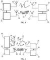
FIG. 3 a diagrammatic view of the sensor probe positioned in a food item which is positioned in an oven which has two antennas for beam steering. -
FIG. 4 a diagrammatic view of the sensor probe positioned in a food item which is positioned in an oven which has four antennas for beam steering. -
FIG. 5 is a diagrammatic view of an illustrative dual band power stealing and data link which can be used in an oven. -
FIG. 6 is a diagrammatic view of an illustrative dual band power stealing and data link with a phase adjusting power transmitter which can be used in an oven. - The description of illustrative embodiments according to principles of the present invention is intended to be read in connection with the accompanying drawings, which are to be considered part of the entire written description. In the description of embodiments of the invention disclosed herein, any reference to direction or orientation is merely intended for convenience of description and is not intended in any way to limit the scope of the present invention. Relative terms such as "lower," "upper," "horizontal," "vertical," "above," "below," "up," "down," "top" and "bottom" as well as derivative thereof (e.g., "horizontally," "downwardly," "upwardly," etc.) should be construed to refer to the orientation as then described or as shown in the drawing under discussion. These relative terms are for convenience of description only and do not require that the apparatus be constructed or operated in a particular orientation unless explicitly indicated as such. Terms such as "attached," "affixed," "connected," "coupled," "interconnected," and similar refer to a relationship wherein structures are secured or attached to one another either directly or indirectly through intervening structures, as well as both movable or rigid attachments or relationships, unless expressly described otherwise.
- Moreover, the features and benefits of the invention are illustrated by reference to the preferred embodiments. Accordingly, the invention expressly should not be limited to such embodiments illustrating some possible nonlimiting combination of features that may exist alone or in other combinations of features, the scope of the invention being defined by the claims appended hereto.
- As shown in
FIGS. 1 and 2 , asensor probe 10 has a needle orprobe portion 12 and ahandle 14. The needle orprobe portion 12 is configured to be inserted or partially inserted into a substance or material, such as, but not limited to meat. Thehandle 14 is configured to be positioned outside or partially outside of the substance or material. - The
probe portion 12 houses acircuit board 16 with a processor or microcontroller. In the illustrative embodiment shown, thecircuit board 16 includes atemperature sensor 18, a radio frequency (RF) transmitter/receiver 20 and apower stealing regulator 21. However, in other illustrative embodiments: thetemperature sensor 18, the RF transmitter/receiver 20 and thepower stealing regulator 21 may be separate components which are electrically connected to thecircuit board 16; thecircuit board 16 does not have a microcontroller; any combination of thecircuit board 16, thetemperature sensor 18, the RF transmitter/receiver 20, or other sensors may be housed in one component; and/or sensors in addition to, or other than, the temperature sensor may be provided, for example, but not limited to a humidity sensor. In alternate embodiments, more than onetemperature probe 18 may be provide at different locations along the length of theprobe portion 12 to allow the temperature of the food to be measured at different locations. - In the illustrative embodiment shown, a
terminal isolation device 22 is provided in theprobe portion 12. Theterminal isolation device 22 may be, but is not limited to, a capacitor or other type of thermal insulator. - The
handle 14 includes ahousing 24 and asensor probe antenna 26. Thesensor probe antenna 26 may have a planar configuration as shown inFIG. 2 . Alternatively, the antenna may have other configurations, such as, but not limited to: dipole or monopole. - When in use, as shown in
FIGS. 3 and 4 , the sensor ormeat probe 10 is positioned in the food ormeat 30 in anoven 32. The oven has anRF power transmitter 34 positioned proximate an oven cavity orcompartment 36. Theoven 32 has an RF data receiver/transceiver 35 positioned proximate an oven cavity orcompartment 36. TheRF power transmitter 34 and the RF data receiver/transceiver 35 are connected to one or more antennas 42 (FIG. 3 ), 44 (FIG. 4 ). - One of the key challenges for a sensor or
meat probe 10 is the high temperature of operation inside anoven 32 or the like. Aside from using high-temperature-rated materials, thecircuit board 16 and other electronics need to be protected from the high heat. Most semiconductor chips are only rated to operational temperatures of 85°C or 125°C. As the temperature in theoven compartment 36 is often in excess of 125°C, any electronics located in a reasonably-sized handle 14 cannot be practically retained under 125°C for 3 hours. As the best insulator inside theoven 32 is thefood 30 itself, thecircuit board 16 and other electronics is positioned in the needle orprobe portion 12 when in use, thereby protecting or insulating the needle orprobe portion 12 by thefood 30. - In order to use the
probe 10, theprobe 10 requires energy for operation. As theprobe 10 does not contain batteries, theprobe 10 must use energy harvesting for operation. The battery-free meat probe 10 requires a mechanism to harvest enough energy to power thecircuit board 16,temperature sensor 18 and the RF transmitter/receiver 20. The RF transmitter/receiver 20 has a unique electronic identification which is distinguishable from other similar devices. - While an obvious source of energy inside an
oven compartment 36 is the heat, theprobe 10 must be operational even when the oven is just beginning to warm-up. In this phase, there is not enough temperature gradient to harvest the required power required for the electronics. Consequently, as shown inFIGS. 3 and 4 , RF energy harvesting using a dedicatedRF power transmitter 34 in theoven 32 is used. As the communication between the RF transmitter/receivers 20 and thepower stealing regulators 21 of theprobe 10 and thepower transmitter 34 and the RF data receiver/transceiver 35 is wireless, the energy in the wireless signal sent from thepower transmitter 34 topower stealing regulators 21 of theprobe 10 is re-purposed, to allow theprobe 10 to operate and respond. - In the illustrative embodiment shown, the system includes the
RF power transmitter 34 and the RF data receiver/transceiver 35 positioned in a wall or other position of theoven 32. Theoven 32, thepower transmitter 34 and the RF data receiver/transceiver 35 are a fixed system, without size restrictions, and are powered by AC current or one or more large batteries. The one or more RF transmitter/receivers 20 andpower stealing regulators 21 of theprobe 10 are smaller, portable, and battery-free systems. The RF transmitter/receivers 20 and thepower stealing regulators 21 are connected to one ormore antennas 26. The system supports communication range of up to approximately one meter using high-powerRF power transmitters 34 and RF data receiver/transceivers 35. The RF data receiver/transceivers 35 can detect multiple RF transmitter/receivers 20 in the vicinity which is beneficial for large ovens where many pieces of food are cooked simultaneously. Alternatively, the oven rack 40 may include theRF power transmitter 34 and the RF data receiver/transceiver 35, thereby allowing for close proximity of thesensor probe 10 to theRF power transmitter 34 and the RF data receiver/transceiver 35 regardless of the position of thefood 30 in the oven cavity orcompartment 36. The oven rack 40 may be positioned in theoven 32 with or without electrical isolation. In another alternate embodiment, the rack 40 may act as a signal enhancer or antenna to facilitate communication with theRF power transmitter 34 and the RF data receiver/transceiver 35 located at another location. In other alternate embodiments, theRF power transmitter 34 and the RF data receiver/transceiver 35 may be located in one, two, three, four or five walls of the oven cavity orcompartment 36 and/or on the door of the oven and/or at any arbitrary position inside the cavity orcompartment 36. TheRF power transmitter 34 may be configurable to radiate in various patterns. - In the illustrative embodiment shown, the
circuit board 16 has a width of approximately 2.6mm and length of approximately 20mm. The smallest trace width and space used for routing is 100µm, and only two metal layers were used for routing all the components on thecircuit board 16. The choice of trace width and number of layers is governed by two factors: ensuring routability of all the components and minimizing manufacturing cost of thecircuit board 16. However,other circuit boards 16 with other dimensions and other configurations may be used. - In the illustrative embodiment shown, the circuit board is fabricated from high-temperature circuit board material with a glass transition temperature of greater than 280°C and thermal degradation temperature of 390°C, such as Rogers 4350. The outside housing of the
probe portion 12 is made from stainless steel or other material which conducts heat. The handle material is Polytetrafluoroethylene (PTFE). - All the materials that are outside the food during operation are chosen to withstand 300°C. In contrast, the
circuit board 16 and other electronics have a maximum recommended operational temperature of 85°C, as the electronics will not be subject to more than 74°C (165°F) during normal operation. However, the use of a high-temperature material for thecircuit board 16 allows thecircuit board 16 to survive accidental exposures to 300°C. - As the stainless-
steel probe portion 12 is small and blocks RF signals, theantenna 26 must be housed in thehandle 14, and be capable of surviving 300°C. In one illustrative embodiment, theantenna 26 has a dimension of approximately 60mm x 16mm. However, other sizes and configurations of the antennas may be used. The dimensions and configurations of theantenna 26 are optimized to allow theprobe 10 to be positioned in theoven compartment 36 at any orientation, allowing proper communication with theRF power transmitter 34 and the RF data receiver/transceiver 35. - The
antenna 26 is made from metal or other conductive material and is exposed to high temperatures in theoven compartment 36. In contrast, thecircuit board 16 is not rated to be operated at high temperatures for long periods of time. Consequently, in order to prevent heat from being conducted through theantenna 26 to thecircuit board 16, thethermal isolation device 22 is provided in line with theantenna 26 proximate thecircuit board 16. Thethermal isolation device 22 is provided to dissipate the heat collected and transmitted by theantenna 26, thereby preventing harmful heat from reaching thecircuit board 16, the RF transmitter/receiver 20 and thepower stealing regulator 21. Thethermal isolation device 22 does not adversely affect the electrical communication between theantenna 26 and thecircuit board 16, the RF transmitter/receiver 20 and thepower stealing regulator 21. - In complex propagation environments, such as inside an oven cavity or
compartment 36, many reflections and refractions combine to create a pattern of 'hotspots' where the field strength is relatively high and deep 'cold spots' where nearly no field intensity exists. Powering an electronic circuit of the sensor or meat probe 10 'over the air' in such an environment can be much more complex than in an open space. The illustrative embodiments ofFIGS. 3 and 4 illustrate systems of multiple energy emitting antenna 42 (FIG. 3 ) and 44 (FIG. 4 ) which are connected to thepower transmitter 34. In alternate embodiments one antenna may be provided with different operation frequency bands. Theantenna power stealing regulator 21 of theprobe 10, as represented by beams or arrows 46 (FIG. 3 ) and 48 (FIG. 4 ). In an enclosed environment, such as theoven cavity 36, thebeams power transmitter 34 in theoven 32 to couple power effectively to thepower stealing regulator 21 is highly desirable to mitigate the situation where thepower stealing regulator 21 is invisible to a fixedantenna transceiver 35 positioned proximate an oven cavity orcompartment 36 and the RF transmitter/receiver 20 in theprobe 10 is highly desirable to mitigate the situation where the RF transmitter/receiver 20 is invisible to a fixedantenna - The
oven 32 can be considered as a sub-optimal form of cavity filter, which has highly complex and sharp frequency responses. The RF or inductive fields are impacted in complex ways by the metal work inside the oven compartment orcavity 36. Other propagation environments with high reflections near the reader and or tag antenna in an energy harvesting system will face similar challenges. - As well as helping to ensure the
power stealing regulator 21 and RF transmitter/receiver 20 are not in a multipath null field location, beam steering array systems have gain. A two element orenergy emitting antenna 42 array, as shown inFIG. 3 , can place four times as much energy or power at the location of thepower stealing regulator 21 and the RF transmitter/receiver 20 assuming eachenergy emitting antenna 42 transmits the same power, providing a 6dB link power advantage. A four element orenergy emitting antenna 44 array, as shown inFIG. 4 , can put 16x energy or power at the location of thepower stealing regulator 21 and the RF transmitter/receiver 20, providing a 12dB link power advantage. As energy coupling is a primary goal of energy harvesting systems these are significant advantages in terms of range or speed of activation. Alternatively, for a given range, the overall transmitted power is lower in an antenna array based energy harvesting system improving emissions and interference with other systems and improving efficiency of operation. - Steering a beam for optimum power transfer to the
power stealing regulator 21 and the RF transmitter/receiver 20 can be facilitated by measurement systems known asreflectometers 50. The circuits orreflectometers 50 are used to measure when power transmitted to theenergy emitting antenna power stealing regulator 21 and the RF transmitter/receiver 20. - In practical implementations the
oven 32 will have other losses including heating of the food by electromagnetic dielectric heating and loss through the oven door. Careful design of the door and selection of the frequency of operation can optimize forantenna power stealing regulator 21 and the RF transmitter/receiver 20. - In various illustrative embodiments, the
beam power stealing regulator 21 is first initialized or activated. A feedback loop can be set up to inform the reader oroven 32 about the quality of the coupling between the multipleenergy emitting antenna receiver 20. This allows for an ongoing and real time optimization driven by algorithms and the feedback from the RF transmitter/receiver 20. This also allows thetransmitter 34 power to be reduced improving the systems efficiency. Reducing the power radiated in other directions is also a health and safety consideration, as well as an efficiency advantage in the case of higher power energy systems. - Referring to
FIG. 5 , a diagrammatic view of a system with onepower transmitter 34 and one RF data receiver/transceiver 35 is shown. In this embodiment, thepower transmitter 34 and the RF data receiver/transceiver 35 are in electrical communication as represented byarrow 52. Thepower transmitter 34 has anantenna 54 and the RF data receiver/transceiver 35 has anantenna 56. However, in other embodiments, thepower transmitter 34 and the RF data receiver/transceiver 35 may share an antenna. - The
probe 10 includes one thepower stealing regulator 21 and one RF transmitter/receiver 20. Thepower stealing regulator 21 and the RF transmitter/receiver 20 are in electrical communication as represented byarrow 58. Thepower stealing regulator 21 has anantenna 60 and the RF transmitter/receiver 20 has anantenna 62. However, in other embodiments, thepower stealing regulator 21 and one RF transmitter/receiver 20 may share an antenna. - In use, the
power transmitter 34 transmits energy in the form of RF signals to thepower stealing regulator 21 as represented byarrow 64. The transmission allows power to be supplied to thepower stealing regulator 21 and theprobe 10 to initially power theprobe 10 and maintain operation of theprobe 10. Once powered, communication between the RF data receiver/transceiver 35 and the RF transmitter/receiver 20 is done wirelessly, as represented byarrow 66. - Referring to
FIG. 6 , a diagrammatic view of a power transmitter 34' and one RF data receiver/transceiver 35 is shown. In this embodiment, the power transmitter 34' is an n-channel phase adjusting power transmitter. The power transmitter 34' and the RF data receiver/transceiver 35 are in electrical communication as represented by arrow 52'. Thepower transmitter 34 has multiple antennas 54' and the RF data receiver/transceiver 35 has anantenna 56. However, in other embodiments, the power transmitter 34' and the RF data receiver/transceiver 35 may share an antenna. - The
probe 10 includes one thepower stealing regulator 21 and one RF transmitter/receiver 20. Thepower stealing regulator 21 and the RF transmitter/receiver 20 are in electrical communication as represented byarrow 58. Thepower stealing regulator 21 has anantenna 60 and the RF transmitter/receiver 20 has anantenna 62. However, in other embodiments, thepower stealing regulator 21 and one RF transmitter/receiver 20 may share an antenna. - In use, the power transmitter 34' transmits energy in the form of RF signals over multiple paths to the
power stealing regulator 21 as represented by arrows 64'. The transmission allows power to be supplied to thepower stealing regulator 21 and theprobe 10 to initially power theprobe 10 and maintain operation of theprobe 10. Once powered, communication between the RF data receiver/transceiver 35 and the RF transmitter/receiver 20 is done wirelessly, as represented byarrow 66. - The embodiments shown and described herein are directed to a sensor probe which is wireless and which does not need batteries, thereby allowing the needle of the sensor probe to have a small diameter. In addition, as no batteries are required, the life of the probe is not limited by battery life and safety concerns of placing batteries in an oven proximate food are eliminated. The probe is a low-cost NFC-based wireless battery-free solution for use with smart ovens.
- The wireless communication of the probe with the oven allows the oven temperature to be regulated based on the actual internal food temperature readings from the probe and not the oven ambient temperature.
- The power harvested can be used to power a separate electronic subsystem which can include a wireless data link operating independently. Alternatively, the same antenna or another communication antenna with different operation frequency band used to collect power can be used to transmit signals back to the energy emitting antennas.
- The underlying beam-steering wireless energy transfer concept will have advantages in other complex propagation environments and also in simple environments where there is a requirement to minimize overall transmitted power while ensuring link robustness or optimizing transfer efficiency. Examples might include communication with a sensor in a noncontact application in industrial systems where access for replacing a battery can be expensive.
- One skilled in the art will appreciate that the invention may be used with many modifications of frequency band, antenna type and number, structure, arrangement, proportions, sizes, materials and components and otherwise used in the practice of the invention, which are particularly adapted to specific environments and operative requirements without departing from the principles of the present invention. The presently disclosed embodiments are therefore to be considered in all respects as illustrative and not restrictive, the scope of the invention being defined by the appended claims, and not limited to the foregoing description or embodiments.
Claims (20)
- A system for measuring the temperature of food (30) in an oven (32), the system comprising:at least one energy emitting antennas (42, 44) positioned in the oven (32) proximate an oven cavity (36), the at least one energy emitting antenna (42, 44) sends signals at the same frequency which are phase shifted relative to each other;a battery-free sensor probe (10) configured to be inserted into the food (30) in the oven cavity (36), the battery-free sensor probe (10) having an antenna (26) to harvest energy transmitted from the at least one energy emitting antenna (42, 44) and to transmit signals back to the at least one energy emitting antenna (42, 44);wherein the phase shifted signals sent by the at least one energy emitting antenna (42, 44) steer the signals sent by the at least one energy emitting antenna (42, 44) to ensure that the signals sent by the at least one energy emitting antenna (42, 44) are received by the antenna (26) of the battery-free sensor probe (10).
- The system as recited in claim 1, wherein the at least one energy emitting antenna (42, 44) is positioned in a wall of the oven cavity (36) of the oven (32).
- The system as recited in claim 1, wherein the at least one energy emitting antenna (42, 44) has power transmitters (34) and data receivers/transceivers (35).
- The system as recited in claim 3, wherein the power transmitters (34) of the at least one energy emitting antenna (42, 44) are N-channel phase adjusting power transmitters (34).
- The system as recited in claim 4, wherein the battery-free sensor probe antenna (26) has a power stealing regulator (21) and a data transmitter/transceiver.
- The system as recited in claim 5, wherein the at least one energy emitting antenna (42, 44) includes reflectometers (50) to measure forward and reflected energy emitted from the at least one energy emitting antenna (42, 44).
- The system as recited in claim 5, wherein the at least one energy emitting antenna (42, 44) projects energy emissions in a search pattern to initially activate the power stealing regulator (21) in the sensor probe (10).
- The system as recited in claim 5, wherein a feedback loop informs the reader about the quality of the coupling between the at least one energy emitting antenna (42, 44) and the power stealing regulator (21) in the sensor probe (10).
- The system as recited in claim 5, wherein the at least one energy emitting antenna (42, 44) are two energy emitting antennas (42) which are spaced from each other.
- The system as recited in claim 5, wherein the at least one energy emitting antenna (42, 44) are four energy emitting antennas (44) which are spaced from each other.
- A system for measuring the temperature of food (30) in an oven (32), the system comprising:multiple energy emitting antennas (42, 44) positioned in the oven (32) proximate an oven cavity (36), the multiple energy emitting antennas (42, 44) having power transmitters (34) and data receivers/transceivers (35), the multiple energy emitting antennas (42, 44) send signals at the same frequency which are phase shifted relative to each other;a battery-free sensor probe (10) configured to be inserted into the food (30) in the oven cavity (36), the battery-free sensor probe (10) having an antenna (26) with a power stealing regulator (21) and a data transmitter/transceiver to harvest energy transmitted from the multiple energy emitting antennas (42, 44) and to transmit signals back to the multiple energy emitting antennas (42, 44);wherein the phase shifted signals sent by the multiple energy emitting antennas (42, 44) steer the signals sent by the multiple energy emitting antennas (42, 44) to ensure that the signals sent by the multiple energy emitting antennas (42, 44) are received by the antenna (26) of the battery-free sensor probe (10).
- The system as recited in claim 11, wherein the multiple energy emitting antennas (42, 44) are positioned in a wall of the oven cavity (36) of the oven (32).
- The system as recited in claim 11, wherein the power transmitters (34) of the multiple energy emitting antennas (42, 44) are N-channel phase adjusting power transmitters (34).
- The system as recited in claim 11, wherein the multiple energy emitting antennas (42, 44) include reflectometers (50) to measure forward and reflected energy emitted from the multiple energy emitting antennas (42, 44).
- The system as recited in claim 11, wherein the multiple energy emitting antennas (42, 44) project energy emissions in a search pattern to initially activate the power stealing regulator (21) in the sensor probe (10).
- The system as recited in claim 11, wherein a feedback loop informs the reader about the quality of the coupling between the multiple energy emitting antennas (42, 44) and the power stealing regulator (21) in the sensor probe (10).
- The system as recited in claim 11, wherein the multiple energy emitting antennas (42, 44) are two energy emitting antennas (42) which are spaced from each other.
- The system as recited in claim 11, wherein the multiple energy emitting antennas (42, 44) are four energy emitting antennas (44) which are spaced from each other.
- A system for measuring the temperature of food (30) in an oven (32), the system comprising:multiple energy emitting antennas (42, 44) positioned in the oven (32) proximate an oven cavity (36), the multiple energy emitting antennas (42, 44) having power transmitters (34) and data receivers/transceivers (35), the multiple energy emitting antennas (42, 44) send signals at the same frequency which are phase shifted relative to each other;a battery-free sensor probe (10) configured to be inserted into the food (30) in the oven cavity (36), the battery-free sensor probe (10) having an antenna (26, 54, 56, 60, 62) with a power stealing regulator (21) and a data transmitter/transceiver to harvest energy transmitted from the multiple energy emitting antennas (42, 44) and to transmit signals back to the multiple energy emitting antennas (42, 44);a feedback loop informs the reader about the quality of the coupling between the power transmitters (34) in the multiple energy emitting antennas (42, 44) and the power stealing regulator (21) in the sensor probe (10);wherein the phase shifted signals sent by the power transmitters (34) in the multiple energy emitting antennas (42, 44) project energy emissions in a search pattern to initially activate the power stealing regulator (21) in the sensor probe (10) to ensure that the signals sent by the multiple energy emitting antennas (42, 44) are received by the antenna (26, 54, 56, 60, 62) of the battery-free sensor probe (10).
- The system as recited in claim 19, wherein a feedback loop informs the reader about the quality of the coupling between the multiple energy emitting antennas (42, 44) and the power stealing regulator (21) in the sensor probe (10).
Priority Applications (3)
| Application Number | Priority Date | Filing Date | Title |
|---|---|---|---|
| EP21163968.7A EP4063810A1 (en) | 2021-03-22 | 2021-03-22 | Wireless energy-harvesting sensor probe utilizing beam steering for in-oven power stealing |
| CN202210264657.3A CN115189487A (en) | 2021-03-22 | 2022-03-17 | Wireless energy collection sensor probe for power stealing in oven by utilizing beam control |
| US17/701,029 US20220299375A1 (en) | 2021-03-22 | 2022-03-22 | Wireless Energy-Harvesting Sensor Probe Utilizing Beam Steering for In-Oven Power Stealing |
Applications Claiming Priority (1)
| Application Number | Priority Date | Filing Date | Title |
|---|---|---|---|
| EP21163968.7A EP4063810A1 (en) | 2021-03-22 | 2021-03-22 | Wireless energy-harvesting sensor probe utilizing beam steering for in-oven power stealing |
Publications (1)
| Publication Number | Publication Date |
|---|---|
| EP4063810A1 true EP4063810A1 (en) | 2022-09-28 |
Family
ID=75143524
Family Applications (1)
| Application Number | Title | Priority Date | Filing Date |
|---|---|---|---|
| EP21163968.7A Pending EP4063810A1 (en) | 2021-03-22 | 2021-03-22 | Wireless energy-harvesting sensor probe utilizing beam steering for in-oven power stealing |
Country Status (3)
| Country | Link |
|---|---|
| US (1) | US20220299375A1 (en) |
| EP (1) | EP4063810A1 (en) |
| CN (1) | CN115189487A (en) |
Citations (4)
| Publication number | Priority date | Publication date | Assignee | Title |
|---|---|---|---|---|
| WO2013001476A1 (en) * | 2011-06-30 | 2013-01-03 | Thirode Grandes Cuisines Poligny | Wave stirring oven |
| US20160123818A1 (en) * | 2013-06-14 | 2016-05-05 | Gea Food Solutions Bakel B.V. | Temperature detection device and heat treatment device |
| IT201800003661A1 (en) * | 2018-03-16 | 2019-09-16 | Italcoppie Sensori S R L | SYSTEM FOR THE DETECTION OF A TEMPERATURE VALUE INSIDE AT LEAST ONE FOOD IN A HEAT TREATMENT APPARATUS |
| EP3779382A1 (en) * | 2019-08-15 | 2021-02-17 | TE Connectivity Corporation | Wireless energy-harvesting sensor probe |
Family Cites Families (8)
| Publication number | Priority date | Publication date | Assignee | Title |
|---|---|---|---|---|
| US4377733A (en) * | 1978-08-31 | 1983-03-22 | Sharp Kabushiki Kaisha | Temperature-sensing probe structure for wireless temperature-sensing system |
| WO2010023237A1 (en) * | 2008-09-01 | 2010-03-04 | Arcelik Anonim Sirketi | An oven with a wireless probe |
| WO2017182076A1 (en) * | 2016-04-20 | 2017-10-26 | Vorwerk & Co. Interholding Gmbh | System for preparing and method for operating a system for preparing at least one food |
| US11723489B2 (en) * | 2017-06-01 | 2023-08-15 | Apption Labs Limited | Temperature sensing devices and wireless communication improvements for cooking appliances |
| US20190041271A1 (en) * | 2017-08-07 | 2019-02-07 | Philip Preston | Method And Assembly For A Wireless Probe And Interrogator |
| EP3788332B1 (en) * | 2018-05-03 | 2023-06-07 | Matrix Product Development, Inc. | Wireless temperature-measurement system |
| CN110870701A (en) * | 2018-08-31 | 2020-03-10 | 青岛海尔智能技术研发有限公司 | Temperature detection device and method, oven, computer equipment and storage medium |
| US20200182703A1 (en) * | 2018-12-11 | 2020-06-11 | Gina Marie Bourret | Methods, Devices, and Systems for Monitoring Temperatures |
-
2021
- 2021-03-22 EP EP21163968.7A patent/EP4063810A1/en active Pending
-
2022
- 2022-03-17 CN CN202210264657.3A patent/CN115189487A/en active Pending
- 2022-03-22 US US17/701,029 patent/US20220299375A1/en active Pending
Patent Citations (4)
| Publication number | Priority date | Publication date | Assignee | Title |
|---|---|---|---|---|
| WO2013001476A1 (en) * | 2011-06-30 | 2013-01-03 | Thirode Grandes Cuisines Poligny | Wave stirring oven |
| US20160123818A1 (en) * | 2013-06-14 | 2016-05-05 | Gea Food Solutions Bakel B.V. | Temperature detection device and heat treatment device |
| IT201800003661A1 (en) * | 2018-03-16 | 2019-09-16 | Italcoppie Sensori S R L | SYSTEM FOR THE DETECTION OF A TEMPERATURE VALUE INSIDE AT LEAST ONE FOOD IN A HEAT TREATMENT APPARATUS |
| EP3779382A1 (en) * | 2019-08-15 | 2021-02-17 | TE Connectivity Corporation | Wireless energy-harvesting sensor probe |
Also Published As
| Publication number | Publication date |
|---|---|
| US20220299375A1 (en) | 2022-09-22 |
| CN115189487A (en) | 2022-10-14 |
Similar Documents
| Publication | Publication Date | Title |
|---|---|---|
| EP3779382B1 (en) | Wireless energy-harvesting sensor probe | |
| US10424940B2 (en) | Smart table and method for operating the same | |
| US20230346159A1 (en) | Temperature sensing devices and wireless communication improvements for cooking appliances | |
| US20090132008A1 (en) | Medical apparatus and system | |
| JP7398579B2 (en) | refrigerator | |
| JP2009250480A (en) | Storage and refrigerator | |
| US20180351232A1 (en) | Wireless communication improvements for cooking appliances | |
| CA3148697A1 (en) | Temperature sensing devices and wireless communication improvements for cooking appliances | |
| EP4063810A1 (en) | Wireless energy-harvesting sensor probe utilizing beam steering for in-oven power stealing | |
| US10641498B2 (en) | Antenna device for a wireless probe system of an oven appliance | |
| KR20170111365A (en) | Storage case for cooling and warming | |
| US9912037B2 (en) | Planar inverted-F wing antenna for wireless culinary appliances | |
| US9947195B2 (en) | Article management system | |
| US11101543B2 (en) | Wireless communication device | |
| JP7430085B2 (en) | refrigerator | |
| Schwartz et al. | An RF-powered self-locating flexible building environment sensor system | |
| JP4552764B2 (en) | Storage device | |
| CN118095325B (en) | High concurrency RFID read-write system and device suitable for cold chain logistics | |
| JPWO2019038941A1 (en) | Cooker | |
| Raktur et al. | Design of Compact Wideband Wearable Antenna for Health Care and Internet of Things System | |
| JP2024061374A (en) | Power transmission device and power transmission method | |
| Mostaccio et al. | Design and Integration of Low Power RFID Wake-Up Radio For the Activation Of Sensing Nodes In Industrial Plants | |
| CN111103069A (en) | Temperature detector and temperature detection system | |
| CN111103068A (en) | Temperature detector and temperature detection system | |
| KR20230082947A (en) | Smart fresh logistics box and artificial intelligence fresh logistics system using the same |
Legal Events
| Date | Code | Title | Description |
|---|---|---|---|
| PUAI | Public reference made under article 153(3) epc to a published international application that has entered the european phase |
Free format text: ORIGINAL CODE: 0009012 |
|
| STAA | Information on the status of an ep patent application or granted ep patent |
Free format text: STATUS: THE APPLICATION HAS BEEN PUBLISHED |
|
| AK | Designated contracting states |
Kind code of ref document: A1 Designated state(s): AL AT BE BG CH CY CZ DE DK EE ES FI FR GB GR HR HU IE IS IT LI LT LU LV MC MK MT NL NO PL PT RO RS SE SI SK SM TR |
|
| STAA | Information on the status of an ep patent application or granted ep patent |
Free format text: STATUS: REQUEST FOR EXAMINATION WAS MADE |
|
| 17P | Request for examination filed |
Effective date: 20230324 |
|
| RBV | Designated contracting states (corrected) |
Designated state(s): AL AT BE BG CH CY CZ DE DK EE ES FI FR GB GR HR HU IE IS IT LI LT LU LV MC MK MT NL NO PL PT RO RS SE SI SK SM TR |