EP4063698A1 - Shaft sealing structure - Google Patents
Shaft sealing structure Download PDFInfo
- Publication number
- EP4063698A1 EP4063698A1 EP22163253.2A EP22163253A EP4063698A1 EP 4063698 A1 EP4063698 A1 EP 4063698A1 EP 22163253 A EP22163253 A EP 22163253A EP 4063698 A1 EP4063698 A1 EP 4063698A1
- Authority
- EP
- European Patent Office
- Prior art keywords
- packings
- side skirt
- skirt portion
- sealing structure
- shaft sealing
- Prior art date
- Legal status (The legal status is an assumption and is not a legal conclusion. Google has not performed a legal analysis and makes no representation as to the accuracy of the status listed.)
- Pending
Links
- 238000007789 sealing Methods 0.000 title claims abstract description 78
- 238000012856 packing Methods 0.000 claims abstract description 162
- 239000012530 fluid Substances 0.000 claims description 32
- 229920001971 elastomer Polymers 0.000 claims description 19
- 229920005989 resin Polymers 0.000 claims description 16
- 239000011347 resin Substances 0.000 claims description 16
- YCKRFDGAMUMZLT-UHFFFAOYSA-N Fluorine atom Chemical compound [F] YCKRFDGAMUMZLT-UHFFFAOYSA-N 0.000 claims description 12
- 229910052731 fluorine Inorganic materials 0.000 claims description 12
- 239000011737 fluorine Substances 0.000 claims description 12
- 239000000463 material Substances 0.000 description 12
- 239000004519 grease Substances 0.000 description 8
- 230000001747 exhibiting effect Effects 0.000 description 7
- 239000000126 substance Substances 0.000 description 6
- 230000002035 prolonged effect Effects 0.000 description 5
- 229920006351 engineering plastic Polymers 0.000 description 4
- 239000003566 sealing material Substances 0.000 description 4
- 238000007599 discharging Methods 0.000 description 3
- 239000004696 Poly ether ether ketone Substances 0.000 description 2
- JUPQTSLXMOCDHR-UHFFFAOYSA-N benzene-1,4-diol;bis(4-fluorophenyl)methanone Chemical compound OC1=CC=C(O)C=C1.C1=CC(F)=CC=C1C(=O)C1=CC=C(F)C=C1 JUPQTSLXMOCDHR-UHFFFAOYSA-N 0.000 description 2
- 238000004891 communication Methods 0.000 description 2
- 239000000470 constituent Substances 0.000 description 2
- 239000000806 elastomer Substances 0.000 description 2
- 239000007788 liquid Substances 0.000 description 2
- 229920002530 polyetherether ketone Polymers 0.000 description 2
- 239000004810 polytetrafluoroethylene Substances 0.000 description 2
- 229920001343 polytetrafluoroethylene Polymers 0.000 description 2
- 229920002943 EPDM rubber Polymers 0.000 description 1
- 229920002449 FKM Polymers 0.000 description 1
- 229920000459 Nitrile rubber Polymers 0.000 description 1
- 239000002033 PVDF binder Substances 0.000 description 1
- 239000004697 Polyetherimide Substances 0.000 description 1
- 239000004721 Polyphenylene oxide Substances 0.000 description 1
- 235000013361 beverage Nutrition 0.000 description 1
- 238000004140 cleaning Methods 0.000 description 1
- 230000000694 effects Effects 0.000 description 1
- 238000005516 engineering process Methods 0.000 description 1
- 230000002708 enhancing effect Effects 0.000 description 1
- 229920006168 hydrated nitrile rubber Polymers 0.000 description 1
- 239000005020 polyethylene terephthalate Substances 0.000 description 1
- 229920001296 polysiloxane Polymers 0.000 description 1
- 229920002981 polyvinylidene fluoride Polymers 0.000 description 1
- 230000003014 reinforcing effect Effects 0.000 description 1
- 230000000717 retained effect Effects 0.000 description 1
- 239000010802 sludge Substances 0.000 description 1
- 230000001954 sterilising effect Effects 0.000 description 1
- 238000004659 sterilization and disinfection Methods 0.000 description 1
Images


Classifications
-
- F—MECHANICAL ENGINEERING; LIGHTING; HEATING; WEAPONS; BLASTING
- F16—ENGINEERING ELEMENTS AND UNITS; GENERAL MEASURES FOR PRODUCING AND MAINTAINING EFFECTIVE FUNCTIONING OF MACHINES OR INSTALLATIONS; THERMAL INSULATION IN GENERAL
- F16J—PISTONS; CYLINDERS; SEALINGS
- F16J15/00—Sealings
- F16J15/16—Sealings between relatively-moving surfaces
- F16J15/18—Sealings between relatively-moving surfaces with stuffing-boxes for elastic or plastic packings
- F16J15/20—Packing materials therefor
-
- F—MECHANICAL ENGINEERING; LIGHTING; HEATING; WEAPONS; BLASTING
- F16—ENGINEERING ELEMENTS AND UNITS; GENERAL MEASURES FOR PRODUCING AND MAINTAINING EFFECTIVE FUNCTIONING OF MACHINES OR INSTALLATIONS; THERMAL INSULATION IN GENERAL
- F16J—PISTONS; CYLINDERS; SEALINGS
- F16J15/00—Sealings
- F16J15/16—Sealings between relatively-moving surfaces
- F16J15/32—Sealings between relatively-moving surfaces with elastic sealings, e.g. O-rings
-
- F—MECHANICAL ENGINEERING; LIGHTING; HEATING; WEAPONS; BLASTING
- F16—ENGINEERING ELEMENTS AND UNITS; GENERAL MEASURES FOR PRODUCING AND MAINTAINING EFFECTIVE FUNCTIONING OF MACHINES OR INSTALLATIONS; THERMAL INSULATION IN GENERAL
- F16K—VALVES; TAPS; COCKS; ACTUATING-FLOATS; DEVICES FOR VENTING OR AERATING
- F16K41/00—Spindle sealings
- F16K41/02—Spindle sealings with stuffing-box ; Sealing rings
- F16K41/04—Spindle sealings with stuffing-box ; Sealing rings with at least one ring of rubber or like material between spindle and housing
-
- F—MECHANICAL ENGINEERING; LIGHTING; HEATING; WEAPONS; BLASTING
- F16—ENGINEERING ELEMENTS AND UNITS; GENERAL MEASURES FOR PRODUCING AND MAINTAINING EFFECTIVE FUNCTIONING OF MACHINES OR INSTALLATIONS; THERMAL INSULATION IN GENERAL
- F16J—PISTONS; CYLINDERS; SEALINGS
- F16J15/00—Sealings
- F16J15/002—Sealings comprising at least two sealings in succession
-
- F—MECHANICAL ENGINEERING; LIGHTING; HEATING; WEAPONS; BLASTING
- F16—ENGINEERING ELEMENTS AND UNITS; GENERAL MEASURES FOR PRODUCING AND MAINTAINING EFFECTIVE FUNCTIONING OF MACHINES OR INSTALLATIONS; THERMAL INSULATION IN GENERAL
- F16J—PISTONS; CYLINDERS; SEALINGS
- F16J15/00—Sealings
- F16J15/16—Sealings between relatively-moving surfaces
- F16J15/162—Special parts or details relating to lubrication or cooling of the sealing itself
-
- F—MECHANICAL ENGINEERING; LIGHTING; HEATING; WEAPONS; BLASTING
- F16—ENGINEERING ELEMENTS AND UNITS; GENERAL MEASURES FOR PRODUCING AND MAINTAINING EFFECTIVE FUNCTIONING OF MACHINES OR INSTALLATIONS; THERMAL INSULATION IN GENERAL
- F16J—PISTONS; CYLINDERS; SEALINGS
- F16J15/00—Sealings
- F16J15/16—Sealings between relatively-moving surfaces
- F16J15/18—Sealings between relatively-moving surfaces with stuffing-boxes for elastic or plastic packings
- F16J15/188—Split assemblies
-
- F—MECHANICAL ENGINEERING; LIGHTING; HEATING; WEAPONS; BLASTING
- F16—ENGINEERING ELEMENTS AND UNITS; GENERAL MEASURES FOR PRODUCING AND MAINTAINING EFFECTIVE FUNCTIONING OF MACHINES OR INSTALLATIONS; THERMAL INSULATION IN GENERAL
- F16J—PISTONS; CYLINDERS; SEALINGS
- F16J15/00—Sealings
- F16J15/16—Sealings between relatively-moving surfaces
- F16J15/32—Sealings between relatively-moving surfaces with elastic sealings, e.g. O-rings
- F16J15/3204—Sealings between relatively-moving surfaces with elastic sealings, e.g. O-rings with at least one lip
- F16J15/3232—Sealings between relatively-moving surfaces with elastic sealings, e.g. O-rings with at least one lip having two or more lips
- F16J15/3236—Sealings between relatively-moving surfaces with elastic sealings, e.g. O-rings with at least one lip having two or more lips with at least one lip for each surface, e.g. U-cup packings
-
- F—MECHANICAL ENGINEERING; LIGHTING; HEATING; WEAPONS; BLASTING
- F16—ENGINEERING ELEMENTS AND UNITS; GENERAL MEASURES FOR PRODUCING AND MAINTAINING EFFECTIVE FUNCTIONING OF MACHINES OR INSTALLATIONS; THERMAL INSULATION IN GENERAL
- F16J—PISTONS; CYLINDERS; SEALINGS
- F16J15/00—Sealings
- F16J15/16—Sealings between relatively-moving surfaces
- F16J15/32—Sealings between relatively-moving surfaces with elastic sealings, e.g. O-rings
- F16J15/3248—Sealings between relatively-moving surfaces with elastic sealings, e.g. O-rings provided with casings or supports
- F16J15/3252—Sealings between relatively-moving surfaces with elastic sealings, e.g. O-rings provided with casings or supports with rigid casings or supports
-
- F—MECHANICAL ENGINEERING; LIGHTING; HEATING; WEAPONS; BLASTING
- F16—ENGINEERING ELEMENTS AND UNITS; GENERAL MEASURES FOR PRODUCING AND MAINTAINING EFFECTIVE FUNCTIONING OF MACHINES OR INSTALLATIONS; THERMAL INSULATION IN GENERAL
- F16K—VALVES; TAPS; COCKS; ACTUATING-FLOATS; DEVICES FOR VENTING OR AERATING
- F16K1/00—Lift valves or globe valves, i.e. cut-off apparatus with closure members having at least a component of their opening and closing motion perpendicular to the closing faces
- F16K1/32—Details
- F16K1/34—Cutting-off parts, e.g. valve members, seats
- F16K1/46—Attachment of sealing rings
-
- F—MECHANICAL ENGINEERING; LIGHTING; HEATING; WEAPONS; BLASTING
- F16—ENGINEERING ELEMENTS AND UNITS; GENERAL MEASURES FOR PRODUCING AND MAINTAINING EFFECTIVE FUNCTIONING OF MACHINES OR INSTALLATIONS; THERMAL INSULATION IN GENERAL
- F16K—VALVES; TAPS; COCKS; ACTUATING-FLOATS; DEVICES FOR VENTING OR AERATING
- F16K41/00—Spindle sealings
- F16K41/02—Spindle sealings with stuffing-box ; Sealing rings
- F16K41/08—Spindle sealings with stuffing-box ; Sealing rings with at least one ring provided with axially-protruding peripheral closing-lip
-
- F—MECHANICAL ENGINEERING; LIGHTING; HEATING; WEAPONS; BLASTING
- F16—ENGINEERING ELEMENTS AND UNITS; GENERAL MEASURES FOR PRODUCING AND MAINTAINING EFFECTIVE FUNCTIONING OF MACHINES OR INSTALLATIONS; THERMAL INSULATION IN GENERAL
- F16J—PISTONS; CYLINDERS; SEALINGS
- F16J15/00—Sealings
- F16J15/16—Sealings between relatively-moving surfaces
- F16J15/32—Sealings between relatively-moving surfaces with elastic sealings, e.g. O-rings
- F16J15/3268—Mounting of sealing rings
- F16J15/3272—Mounting of sealing rings the rings having a break or opening, e.g. to enable mounting on a shaft otherwise than from a shaft end
-
- F—MECHANICAL ENGINEERING; LIGHTING; HEATING; WEAPONS; BLASTING
- F16—ENGINEERING ELEMENTS AND UNITS; GENERAL MEASURES FOR PRODUCING AND MAINTAINING EFFECTIVE FUNCTIONING OF MACHINES OR INSTALLATIONS; THERMAL INSULATION IN GENERAL
- F16K—VALVES; TAPS; COCKS; ACTUATING-FLOATS; DEVICES FOR VENTING OR AERATING
- F16K1/00—Lift valves or globe valves, i.e. cut-off apparatus with closure members having at least a component of their opening and closing motion perpendicular to the closing faces
- F16K1/02—Lift valves or globe valves, i.e. cut-off apparatus with closure members having at least a component of their opening and closing motion perpendicular to the closing faces with screw-spindle
- F16K1/06—Special arrangements for improving the flow, e.g. special shape of passages or casings
- F16K1/10—Special arrangements for improving the flow, e.g. special shape of passages or casings in which the spindle is inclined to the general direction of flow
Definitions
- the present invention relates to a shaft sealing structure arranged on a sliding portion of a rod.
- a technology has been known in which a shaft seal formed of V-packings are arranged between a rod operating within a liquid such as a chemical or steam, and a body in which the rod is accommodated.
- a valve rod seal for providing sealing between a valve rod and a valve body
- a structure is disclosed in which a V-packing made of a fluorine rubber is sandwiched between V-packings made of a fluorine resin. Consequently, attempts are being undertaken to secure a wider range of sealing performance from low temperatures to high temperatures.
- Such V-packings are pressed strongly against the valve rod and the valve body due to a reaction force of the spring.
- JP H03-096468 U as packings that are mounted between a piston and a cylinder head of a fluid pressure feeding device, a structure is disclosed in which V-packings made of a fluorine resin are stacked in multiple stages.
- the thickness of the top portion thereof is thinner than that of the other portions, and a rear side apex angle thereof is smaller than a front side apex angle.
- the V-packings of this type which are stacked in multiple stages are formed with a structure in which the sealing portions of the packings are strongly pressed against a target member while being mutually pressed in contact with each other, which results in a large amount of wear on the sealing portions. Further, wearing of all of the V-packings progresses simultaneously. Therefore, there is a concern that the useful lifetime of the shaft seal may be shortened.
- the present invention has the object of solving the aforementioned problem.
- a shaft sealing structure is arranged between a rod configured to be driven within a predetermined fluid and move in an axial direction, and a holder in which the rod is accommodated, the shaft sealing structure comprising a plurality of V-packings stacked in multiple stages.
- Each of the V-packings is formed of a top portion formed to be thick-walled and having an annular shape, an inner side skirt portion formed to be thin-walled and extending diagonally inward from the top portion, and an outer side skirt portion formed to be thin-walled and extending diagonally outward from the top portion.
- the inner side skirt portion slidably contacts an outer surface of the rod at a distal end of the inner side skirt portion, and the outer side skirt portion abuts against an inner surface of the holder at a distal end of the outer side skirt portion. Adjacent ones of the top portions abut against each other, adjacent ones of the inner side skirt portions do not interfere with each other, and adjacent ones of the outer side skirt portions do not interfere with each other.
- a shaft sealing structure is arranged between a rod configured to be driven within a predetermined fluid and move in an axial direction, and a holder in which the rod is accommodated, the shaft sealing structure comprising a plurality of U-packings stacked in multiple stages.
- Each of the U-packings is formed of a top portion formed to be thick-walled and having an annular shape, an inner side skirt portion formed to be thin-walled and extending inwardly and in an axial direction from the top portion, and an outer side skirt portion formed to be thin-walled and extending outwardly and in the axial direction from the top portion.
- the inner side skirt portion includes a rib configured to slidably contact an outer surface of the rod
- the outer side skirt portion includes a rib configured to abut against an inner surface of the holder. Adjacent ones of the top portions abut against each other, adjacent ones of the inner side skirt portions do not interfere with each other, and adjacent ones of the outer side skirt portions do not interfere with each other.
- the V-packings or the U-packings can exhibit satisfactory sealing performance. Further, since wearing of the plurality of V-packings or the plurality of U-packings does not progress simultaneously, satisfactory sealing performance can be maintained over a prolonged period of time.
- the shaft sealing structures according to the present invention include the plurality of V-packings or the plurality of U-packings that are formed of the thick-walled top portion, the thin-walled inner side skirt portion, and the thin-walled outer side skirt portion, wherein the adjacent ones of the inner side skirt portions do not interfere with each other, and the adjacent ones of the outer side skirt portions do not interfere with each other. Therefore, satisfactory sealing performance can be maintained over a prolonged period of time.
- FIGS. 1 and 2 an angle seat valve 10 is shown in which the shaft sealing structure 12 is adopted.
- the angle seat valve 10 is used, for example, in order to control flowing of a fluid such as a chemical solution for cleaning a beverage container, or steam for carrying out steam sterilization on medical equipment or the like (hereinafter, simply referred to as a "fluid").
- the angle seat valve 10 is particularly suitable for controlling a large flow rate.
- the angle seat valve 10 includes a valve mechanism unit and a drive mechanism unit.
- the valve mechanism unit is equipped with a valve body 38 and a valve rod (rod) 32.
- the drive mechanism unit includes a cylinder tube 56 and a piston 58.
- the valve body 38 includes a straight tubular shaped main pipe portion 40 having a fluid passage 40a in the interior thereof, and an inclined pipe portion 42 that diagonally intersects the main pipe portion 40.
- the inclined pipe portion 42 is formed integrally with the main pipe portion 40.
- An axis CL2 of the inclined pipe portion 42 intersects an axis CL1 of the main pipe portion 40 at a predetermined angle (for example, 45 degrees).
- One end part of the main pipe portion 40 is equipped with an inlet port 40b, and another end part of the main pipe portion 40 is equipped with an outlet port 40c.
- the interior of the inclined pipe portion 42 is connected to the fluid passage 40a of the main pipe portion 40.
- a bottom wall of the main pipe portion 40 includes a raised portion 40d thereon that protrudes toward the inclined pipe portion 42.
- the valve body 38 includes an annular valve seat 40e, which extends from an inner wall of the valve body 38 at a portion where the main pipe portion 40 and the inclined pipe portion 42 intersect each other at an obtuse angle, to the raised portion 40d.
- the valve seat 40e constitutes an annular sealing surface disposed perpendicularly to the axis CL2 of the inclined pipe portion 42.
- a bottomed cylindrical holder 34 is attached to an upper part of the inclined pipe portion 42. Specifically, a large-diameter hole portion 42b having a female screw thread thereon is formed on an upper inner circumference of the inclined pipe portion 42 via a stepped portion 42a. A large diameter part 34b is formed on a lower outer circumference of the holder 34 via a first stepped portion 34a (see FIG. 3 ). The holder 34 is fitted into the large diameter hole portion 42b of the inclined pipe portion 42 until reaching a position where the large diameter part 34b of the holder 34 abuts against the stepped portion 42a of the inclined pipe portion 42.
- a fixing cylindrical body 54 having a male screw thread thereon is inserted from an upper side of the inclined pipe portion 42 between the holder 34 and the inclined pipe portion 42. Then, the fixing cylindrical body 54 is screwed-engaged with the inclined pipe portion 42, and a distal end of the fixing cylindrical body 54 abuts against the first stepped portion 34a of the holder 34, whereby the holder 34 is fixed to the inclined pipe portion 42.
- a sealing material 36a which is placed in contact with a wall surface of the large diameter hole portion 42b of the inclined pipe portion 42, is mounted on the large diameter part 34b of the holder 34.
- An upper part of the holder 34 extends upwardly from the inclined pipe portion 42, and a later-described rod cover 66 is attached to an end part thereof.
- a first guide bush 24 and a second guide bush 26 are attached to an inner circumference of the holder 34.
- the first guide bush 24 and the second guide bush 26 guide the valve rod 32 so as to be capable of moving in an axial direction.
- a pressing plate 28 is attached to a lower end of the holder 34.
- a scraper 30 and a plurality of V-packings 14a to 14c are mounted between the pressing plate 28 and the first guide bush 24.
- An auxiliary packing 22 is mounted between the first guide bush 24 and the second guide bush 26.
- a valve element 44 which is capable of abutting against the valve seat 40e is connected to a lower end part of the valve rod 32.
- the valve element 44 includes an upwardly opening bottomed hole portion 44a and a pair of pin holes 44b.
- the hole portion 44a extends along the axis CL2 of the valve element 44 (in common with the axis of the inclined pipe portion 42).
- Each of the pin holes 44b extends in a direction perpendicular to the axis CL2 of the valve element 44, and opens on a wall surface of the hole portion 44a and a side surface of the valve element 44.
- the lower end part of the valve rod 32 includes a pin hole 32a.
- the pin hole 32a extends in a direction perpendicular to the axis CL2 of the valve rod 32, and penetrates in a lateral direction through the valve rod 32.
- the valve element 44 is arranged inside the inclined pipe portion 42.
- a seal member 46 which is mounted on the valve element 44 is placed in contact with the valve seat 40e, and communication between the inlet port 40b and the outlet port 40c is interrupted.
- the direction in which the valve element 44 moves is inclined at a predetermined angle with respect to the direction in which the fluid flows from the inlet port 40b toward the outlet port 40c.
- the members indicated by the reference numerals 50 and 52 are a nut and a washer for fixing the seal member 46 to the valve element 44.
- the valve rod 32 is inserted into the first guide bush 24 and the second guide bush 26, and extends upwardly from the holder 34.
- An upper end part of the valve rod 32 is reduced in diameter, and is formed with a small diameter part 32b having a male screw thread formed on a distal end thereof.
- a reinforcing plate 74, the piston 58, and a washer 76 are inserted over the small diameter part 32b of the valve rod 32, and a connecting rod 78 is screw-engaged with the small diameter part 32b from an outer side thereof, whereby the piston 58 is attached to the upper end part of the valve rod 32.
- the piston 58 is arranged inside the cylindrical cylinder tube 56.
- the upper end side of the cylinder tube 56 is closed by a head cover 62 and a cap 64.
- the lower end side of the cylinder tube 56 is closed by the rod cover 66.
- a pressure chamber 70 into which air pressure can be introduced exists between the piston 58 and the rod cover 66.
- Supplying and discharging of air to and from the pressure chamber 70 is carried out via a supply and discharge port 66a of the rod cover 66.
- the reference numeral 67a indicates a port for discharging air or the like within a chamber 67 that exists between the piston 58 and the head cover 62.
- a pair of springs 72a and 72b that bias the piston 58 downward are arranged between the piston 58 and the head cover 62.
- a piston packing 60 in sliding contact with the cylinder tube 56 is mounted on an outer circumference of the piston 58.
- a sealing material 36b, which abuts against the rod cover 66, and a sealing material 36c, which is in sliding contact with the valve rod 32, are mounted on the holder 34. Due to such sealing materials, the pressure chamber 70 is maintained in an airtight state from the exterior, and the pressure chamber 70 is maintained in an airtight state from an internal space of the holder 34.
- each of the V-packings 14a to 14c are made of a fluorine resin, and are superior in chemical resistance and steam resistance. As shown in FIG. 4 , each of the V-packings 14a to 14c, which are V-shaped in cross section, includes a thick-walled top portion 16, a thin-walled inner side skirt portion 18 extending diagonally inward from the top portion 16, and a thin-walled outer side skirt portion 20 extending diagonally outward from the top portion 16.
- the top portion 16 includes an annular convex portion 16a that protrudes to a side opposite to the inner side skirt portion 18 and the outer side skirt portion 20.
- the plurality of V-packings 14a to 14c are arranged in such a manner that the respective top portions 16 thereof are positioned away from the valve element 44, and the V-packings 14a to 14c are stacked in a direction of the axis CL2 of the valve rod 32 (in common with the axis of the inclined pipe portion 42).
- the top portions 16 of adjacent ones of the V-packings 14a to 14c abut against each other by the convex portion 16a of one of the adjacent top portions 16 abutting against a rear surface 16b of the other of the adjacent top portions 16.
- the inner side skirt portions 18 and the outer side skirt portions 20 of the adjacent ones of the V-packings 14a to 14c face each other with gaps therebetween, and do not interfere with each other.
- the inner side skirt portions 18 of the V-packings 14a to 14c slidably contact an outer surface of the valve rod 32 at distal end inner circumferential portions 18a thereof.
- the outer side skirt portions 20 of the V-packings 14a to 14c abut against an inner surface of the holder 34 at distal end outer circumferential portions 20a thereof.
- V-packings 14a to 14c are provided including a lower V-packing 14a, a middle V-packing 14b, and an upper V-packing 14c, the number of the V-packings is not necessarily limited to this feature.
- the auxiliary packing 22 is made of a rubber material such as FKM, and is superior in sealing performance.
- the auxiliary packing 22, which is U-shaped in cross-section, includes an annular plate portion 22a, an inner side cylindrical portion 22b that extends from an inner circumferential portion of the annular plate portion 22a, and an outer side cylindrical portion 22c that extends from an outer circumferential portion of the annular plate portion 22a.
- the inner side cylindrical portion 22b of the auxiliary packing 22 slidably contacts the outer surface of the valve rod 32 on the inner circumference thereof.
- the outer side cylindrical portion 22c of the auxiliary packing 22 abuts against the inner surface of the holder 34 on the outer circumference thereof.
- the first guide bush 24 which is made of a resin such as PPS, is caught and positioned by a second stepped portion 34c provided on the inner circumference of the holder 34.
- the first guide bush 24 is equipped with a recessed portion 24a in which the upper V-packing 14c is accommodated, and abuts against the convex portion 16a of the upper V-packing 14c on the bottom surface of the recessed portion 24a.
- the first guide bush 24 is equipped with a protruding portion 24b which enters between the inner side cylindrical portion 22b and the outer side cylindrical portion 22c of the auxiliary packing 22.
- the second guide bush 26 which is made of a resin such as PPS, is caught and positioned by a third stepped portion 34d provided on the inner circumference of the holder 34.
- a lower end surface of the second guide bush 26 abuts against the annular plate portion 22a of the auxiliary packing 22.
- the scraper 30 for removing foreign material is made of a resin such as PEEK, and is positioned by the pressing plate 28.
- a top portion of the scraper 30 abuts against the rear surface 16b of the top portion 16 of the lower V-packing 14a.
- the plurality of V-packings 14a to 14c are sandwiched between the scraper 30 and the first guide bush 24, and the adjacent ones of the top portions 16 are pressed against each other.
- the angle seat valve 10 which includes the shaft sealing structure 12 in which the plurality of V-packings 14a to 14c and the auxiliary packing 22 are included, is configured in the manner described above. Next, a description will be given concerning actions and operations of the angle seat valve 10.
- a state in which the seal member 46 of the valve element 44 is placed in contact with the valve seat 40e is defined as an initial state.
- air is not introduced into the pressure chamber 70, and the piston 58 is positioned at the lowermost end due to the biasing force of the springs 72a and 72b.
- the fluid pressure acts on a lower end surface of the valve element 44.
- the biasing force of the springs 72a and 72b is greater than the force of the fluid pressure that presses the valve element 44 upward, the valve element 44 does not move.
- a non-illustrated switching valve is operated, and air is supplied from the supply and discharge port 66a to the pressure chamber 70.
- a force that presses the piston 58 upward by the air pressure acting on the piston 58 exceeds the biasing force of the springs 72a and 72b, and the piston 58 moves upward.
- the piston 58 moves to a position where the force that presses the piston 58 upward by the air pressure accumulated in the pressure chamber 70 and the force that presses the piston 58 downward by the reaction force of the contracted springs 72a and 72b are in balance (refer to FIG. 5 ).
- the force that presses the piston 58 upward there is included a force obtained by multiplying the pressure of the fluid acting on the valve element 44 by the cross-sectional area of the valve rod 32.
- valve element 44 separates away from the valve seat 40e, and the fluid supplied from the inlet port 40b is discharged from the outlet port 40c at a flow rate corresponding to the distance between the valve element 44 and the valve seat 40e separated from each other.
- the switching valve is operated, and the air in the pressure chamber 70 is discharged to the exterior from the supply and discharge port 66a.
- the piston 58 moves to the lowermost end due to the biasing force of the springs 72a and 72b, and the seal member 46 of the valve element 44 is placed in contact with the valve seat 40e. Consequently, communication between the inlet port 40b and the outlet port 40c is interrupted, and discharging of the fluid from the outlet port 40c is stopped.
- the fluid supplied from the inlet port 40b fills the inclined pipe portion 42 each time that the valve element 44 separates away from the valve seat 40e.
- the shaft sealing structure 12 in which the plurality of V-packings 14a to 14c and the auxiliary packing 22 are included the fluid inside the inclined pipe portion 42 is prevented from leaking out to the exterior.
- the lower V-packing 14a receives the pressure of the fluid inside the inclined pipe portion 42, the thin-walled inner side skirt portion 18 is elastically deformed, and the pressure at which the distal end inner circumferential portion 18a abuts against the outer surface of the valve rod 32 increases. Further, the thin-walled outer side skirt portion 20 is elastically deformed, and the pressure at which the distal end outer circumferential portion 20a abuts against the inner surface of the holder 34 increases. Consequently, the lower V-packing 14a exhibits a high sealing performance, and the fluid in the inclined pipe portion 42 is effectively suppressed from passing through the lower V-packing 14a. In the case that a slight amount of fluid passes through the lower V-packing 14a, the auxiliary packing 22 prevents the fluid from leaking to the exterior.
- the sealing action is sequentially handed over from the downwardly positioned V-packing to the upwardly positioned V-packing. It should be noted that wearing of the V-packings 14a to 14c progresses particularly at the distal end inner circumferential portions 18a of the inner side skirt portions 18 that repeatedly slide in contact with the reciprocating valve rod 32.
- the inner side skirt portions 18 and the outer side skirt portions 20 of the V-packings 14a to 14c are formed to be thin-walled, they are easily elastically deformed when subjected to the pressure of the fluid inside the inclined pipe portion 42, and are capable of exhibiting satisfactory sealing performance. Further, since the adjacent ones of the V-packings 14a to 14c abut against each other at the top portions 16 which are formed to be thick-walled and have highly rigidity, the gaps between the inner side skirt portions 18 and the outer side skirt portions 20 of the adjacent ones of the V-packings 14a to 14c are reliably retained.
- the shaft sealing structure 12 includes the plurality of V-packings 14a to 14c that are formed of the thick-walled top portions 16, the thin-walled inner side skirt portions 18, and the thin-walled outer side skirt portions 20.
- the adjacent ones of the inner side skirt portions 18 and the outer side skirt portions 20 do not interfere with each other, satisfactory sealing performance can be maintained over a prolonged period of time.
- the V-packings 14a to 14c are made of a fluorine resin
- the V-packings may be made of a resin other than a fluorine resin, rubber, an elastomer or the like, as long as the material has a predetermined elasticity.
- the auxiliary packing 22 which is made of a rubber material is useful for enhancing the sealing performance.
- the auxiliary packing 22 need not necessarily be provided.
- the shaft sealing structure 12 can be applied to various devices (valves) for fluids such as compressed air.
- a shaft sealing structure 80 according to a second embodiment of the present invention will be described with reference to FIGS. 6 and 7 .
- the shaft sealing structure 80 will be described as being applied to the same angle seat valve 10 as in the first embodiment.
- the same reference numerals designate the same or equivalent constituent elements as those of the shaft sealing structure 12 according to the first embodiment, and detailed description thereof is omitted.
- the shaft sealing structure 80 includes a plurality of U-packings 82a to 82c made of a fluorine resin. As shown in FIG. 7 , each of the U-packings 82a to 82c, which are U-shaped in cross section, includes a thick-walled top portion 84, a thin-walled inner side skirt portion 86 extending inwardly and in an axial direction from the top portion 84, and a thin-walled outer side skirt portion 88 extending outwardly and in the axial direction from the top portion 84. Moreover, the "axial direction" referred to herein is a direction parallel to a central axis of the U-packings 82a to 82c which coincides with the axis CL2 of the valve rod 32.
- the plurality of U-packings 82a to 82c are arranged in such a manner that the respective top portions 84 thereof are positioned away from the valve element 44, and the U-packings 82a to 82c are stacked in a direction of the axis CL2 of the valve rod 32.
- the present embodiment as shown in FIG. 6 , although a total of three U-packings 82a to 82c are provided including a lower U-packing 82a, a middle U-packing 82b, and an upper U-packing 82c, the number of the U-packings is not necessarily limited to this feature.
- the inner side skirt portion 86 of each of the U-packings 82a to 82c is provided with a plurality of inwardly protruding annular ribs 86a.
- the outer side skirt portion 88 of each of the U-packings 82a to 82c is provided with a plurality of outwardly protruding annular ribs 88a.
- the inner side skirt portions 86 and the outer side skirt portions 88 which are formed to be thin-walled, are elastically deformed when subjected to the pressure of the fluid inside the inclined pipe portion 42. Then, the inner side skirt portions 86 slidably contact the outer surface of the valve rod 32 at the distal ends of the plurality of ribs 86a.
- outer side skirt portions 88 abut against the inner surface of the holder 34 at the distal ends of the plurality of ribs 88a. Consequently, at the contact portions thereof, it is possible to secure a surface pressure and a contact area that are greater than or equal to a predetermined value, and satisfactory sealing performance can be exhibited.
- end surfaces 84a and rear surfaces 84b of the top portions 84 of the U-packings 82a to 82c are both flat surfaces.
- the top portions 84 of adjacent ones of the U-packings 82a to 82c abut against each other in a state in which the end surface 84a of one of the adjacent top portions 84 abuts against the rear surface 84b of the other of the adjacent top portions 84, in other words, the two flat surfaces abut against each other. Consequently, the central axes of the plurality of stacked U-packings 82a to 82c are stably kept coinciding with each other.
- the length in the axial direction of the top portions 84 of the U-packings 82a to 82c is longer than a distance from the rear surfaces 84b of the top portions 84 to the distal ends of the inner side skirt portions 86 or the distal ends of the outer side skirt portions 88. Stated otherwise, the thickness T of the top portions 84 is greater than the depth D of the recesses formed by the inner side skirt portions 86 and the outer side skirt portions 88. Consequently, the inner side skirt portions 86 and the outer side skirt portions 88 of the adjacent ones of the U-packings 82a to 82c do not interfere with each other.
- the shaft sealing structure 80 includes the plurality of U-packings 82a to 82c that are formed of the thick-walled top portions 84, the thin-walled inner side skirt portions 86, and the thin-walled outer side skirt portions 88.
- the adjacent ones of the inner side skirt portions 86 and the outer side skirt portions 88 do not interfere with each other, satisfactory sealing performance can be maintained over a prolonged period of time.
- the U-packings 82a to 82c are made of a fluorine resin
- the U-packings may be made of a resin other than a fluorine resin, rubber, an elastomer or the like, as long as the material has a predetermined elasticity.
- a shaft sealing structure 90 in the form of a reference example is shown in FIG. 8 .
- This shaft sealing structure 90 differs from the shaft sealing structure 12 according to the first embodiment in that only one V-packing is provided therein.
- the same reference numerals designate the same or equivalent constituent elements as those of the shaft sealing structure 12 according to the first embodiment.
- a description will be given concerning the shaft sealing structure 90.
- the first guide bush 24 and the second guide bush 26 are attached to the inner circumference of the holder 34.
- the first guide bush 24 and the second guide bush 26 guide the valve rod 32 so as to be capable of moving in an axial direction.
- the pressing plate 28 is attached to the lower end of the holder 34.
- the scraper 30 and the single V-packing 14 are mounted between the pressing plate 28 and the first guide bush 24.
- a rubber seal packing 22 is mounted between the first guide bush 24 and the second guide bush 26.
- the V-packing 14 is made of a fluorine resin such as PTFE or PFA, and is superior in chemical resistance, heat resistance, and steam resistance.
- the top portion 16 includes the annular convex portion 16a that protrudes to a side opposite to the inner side skirt portion 18 and the outer side skirt portion 20.
- the inner side skirt portion 18 of the V-packing 14 slidably contacts the outer surface of the valve rod 32 at the distal end inner circumferential portion 18a thereof.
- the outer side skirt portion 20 of the V-packing 14 abuts against the inner surface of the holder 34 at the distal end outer circumferential portion 20a thereof.
- the rubber seal packing 22 is made of a rubber material such as NBR, HNBR, EPDM, FKM, or silicone, and is superior in sealing performance.
- the rubber seal packing 22, which is U-shaped in cross-section, includes the annular plate portion 22a, the inner side cylindrical portion 22b that extends from the inner circumferential portion of the annular plate portion 22a, and the outer side cylindrical portion 22c that extends from the outer circumferential portion of the annular plate portion 22a.
- the inner side cylindrical portion 22b of the rubber seal packing 22 slidably contacts the outer surface of the valve rod 32 on the inner circumference thereof.
- the outer side cylindrical portion 22c of the rubber seal packing 22 abuts against the inner surface of the holder 34 on the outer circumference thereof.
- the first guide bush 24 is made of a super engineering plastic material having a high mechanical strength, a high sliding ability, a heat resistance, and a low wear rate.
- a super engineering plastic material there may be cited PPS, PVDF, PA, PC, PE, POM, PEI, PPO, PET, PTFE, PEEK, PAI, PI, and PBI.
- the first guide bush 24 is caught by the second stepped portion 34c provided on the inner circumference of the holder 34.
- the first guide bush 24 is equipped with the recessed portion 24a in which the V-packing 14 is accommodated, and abuts against the convex portion 16a of the V-packing 14 on the bottom surface of the recessed portion 24a. Further, the first guide bush 24 is equipped with the protruding portion 24b which enters between the inner side cylindrical portion 22b and the outer side cylindrical portion 22c of the rubber seal packing 22.
- the first guide bush 24 includes a plurality of first grease reservoirs 24c that open on the bottom surface of the recessed portion 24a, and an annular second grease reservoir 24d that opens toward the rubber seal packing 22.
- the plurality of first grease reservoirs 24c are uniformly arranged in the circumferential direction.
- the grease that is stored in the plurality of first grease reservoirs 24c is supplied to the V-packing 14.
- the grease that is stored in the second grease reservoir 24d is supplied to the rubber seal packing 22. Since the first guide bush 24 is disposed above the V-packing 14, the first guide bush 24 is protected from the fluid by the V-packing 14, and the durability thereof is enhanced.
- the second guide bush 26 is made of a super engineering plastic material having a high mechanical strength, a high sliding ability, a heat resistance, and a low wear rate.
- the second guide bush 26 is caught by the third stepped portion 34d provided on the inner circumference of the holder 34.
- the lower end surface of the second guide bush 26 abuts against the annular plate portion 22a of the rubber seal packing 22.
- the second guide bush 26 includes a grease reservoir 26a on an inner circumferential surface thereof that faces the valve rod 32. Since the valve rod 32 is supported over a sufficient length by the first guide bush 24 and the second guide bush 26, the stability with which the valve rod 32 is supported is improved.
- the scraper 30 is made of a super engineering plastic material having a heat resistance, a steam resistance, a chemical resistance, a high mechanical strength, a high sliding ability, and a low wear rate.
- the scraper 30 prevents foreign material such as sludge within the fluid that adheres to the valve rod 32 from entering the interior of the shaft sealing structure 90.
- the scraper 30 is positioned by the pressing plate 28. An upper end part of the scraper 30 abuts against the rear surface 16b of the top portion 16 of the V-packing 14.
- the V-packing 14 is arranged between the first guide bush 24 and the scraper 30.
- the top portion 16 of the V-packing 14 is sandwiched between the bottom surface of the recessed portion 24a of the first guide bush 24 and the upper end part of the scraper 30.
- the inner side skirt portion 18 and the outer side skirt portion 20 of the V-packing 14 can be freely deformed inside a space formed between the first guide bush 24 and the scraper 30. Since the inner side skirt portion 18 and the outer side skirt portion 20 of the V-packing 14 are formed to be thin-walled, they are easily elastically deformed when subjected to the pressure of the fluid, and exhibit satisfactory sealing performance.
- the shaft sealing structure 90 includes only one V-packing 14, the durability of the seal is somewhat inferior to that of the aforementioned shaft sealing structure 12 in which the plurality of V-packings 14a to 14c are included.
- the configuration in which the first guide bush 24 and the scraper 30 are included is useful in a similar manner as the aforementioned shaft sealing structure 12, and such a configuration is practical in consideration of cost effectiveness.
Abstract
Description
- The present invention relates to a shaft sealing structure arranged on a sliding portion of a rod.
- Conventionally, a technology has been known in which a shaft seal formed of V-packings are arranged between a rod operating within a liquid such as a chemical or steam, and a body in which the rod is accommodated. For example, in
JP H04-049282 U - Further, for example, in
JP H03-096468 U - However, the V-packings of this type which are stacked in multiple stages are formed with a structure in which the sealing portions of the packings are strongly pressed against a target member while being mutually pressed in contact with each other, which results in a large amount of wear on the sealing portions. Further, wearing of all of the V-packings progresses simultaneously. Therefore, there is a concern that the useful lifetime of the shaft seal may be shortened.
- The present invention has the object of solving the aforementioned problem.
- A shaft sealing structure according to the present invention is arranged between a rod configured to be driven within a predetermined fluid and move in an axial direction, and a holder in which the rod is accommodated, the shaft sealing structure comprising a plurality of V-packings stacked in multiple stages. Each of the V-packings is formed of a top portion formed to be thick-walled and having an annular shape, an inner side skirt portion formed to be thin-walled and extending diagonally inward from the top portion, and an outer side skirt portion formed to be thin-walled and extending diagonally outward from the top portion. The inner side skirt portion slidably contacts an outer surface of the rod at a distal end of the inner side skirt portion, and the outer side skirt portion abuts against an inner surface of the holder at a distal end of the outer side skirt portion. Adjacent ones of the top portions abut against each other, adjacent ones of the inner side skirt portions do not interfere with each other, and adjacent ones of the outer side skirt portions do not interfere with each other.
- Further, a shaft sealing structure according to the present invention is arranged between a rod configured to be driven within a predetermined fluid and move in an axial direction, and a holder in which the rod is accommodated, the shaft sealing structure comprising a plurality of U-packings stacked in multiple stages. Each of the U-packings is formed of a top portion formed to be thick-walled and having an annular shape, an inner side skirt portion formed to be thin-walled and extending inwardly and in an axial direction from the top portion, and an outer side skirt portion formed to be thin-walled and extending outwardly and in the axial direction from the top portion. The inner side skirt portion includes a rib configured to slidably contact an outer surface of the rod, and the outer side skirt portion includes a rib configured to abut against an inner surface of the holder. Adjacent ones of the top portions abut against each other, adjacent ones of the inner side skirt portions do not interfere with each other, and adjacent ones of the outer side skirt portions do not interfere with each other.
- In accordance with the above-described shaft sealing structures, by the inner side skirt portions and the outer side skirt portions receiving a fluid pressure and being elastically deformed thereby, the V-packings or the U-packings can exhibit satisfactory sealing performance. Further, since wearing of the plurality of V-packings or the plurality of U-packings does not progress simultaneously, satisfactory sealing performance can be maintained over a prolonged period of time.
- The shaft sealing structures according to the present invention include the plurality of V-packings or the plurality of U-packings that are formed of the thick-walled top portion, the thin-walled inner side skirt portion, and the thin-walled outer side skirt portion, wherein the adjacent ones of the inner side skirt portions do not interfere with each other, and the adjacent ones of the outer side skirt portions do not interfere with each other. Therefore, satisfactory sealing performance can be maintained over a prolonged period of time.
- The above and other objects, features, and advantages of the present invention will become more apparent from the following description when taken in conjunction with the accompanying drawings, in which preferred embodiments of the present invention are shown by way of illustrative example.
-
-
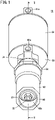
FIG. 1 is an external view of an angle seat valve in which a shaft sealing structure according to a first embodiment of the present invention is adopted; -
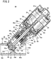
FIG. 2 is a cross-sectional view taken along line II-II of the angle seat valve shown inFIG. 1 ; -
FIG. 3 is an enlarged view of the shaft sealing structure in the angle seat valve shown inFIG. 2 ; -
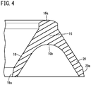
FIG. 4 is a cross-sectional view of a V-packing in the shaft sealing structure shown inFIG. 3 ; -
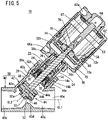
FIG. 5 is a view corresponding toFIG. 2 at a time when the angle seat valve shown inFIG. 1 is in a predetermined operational state; -
FIG. 6 is a view corresponding toFIG. 3 and showing a shaft sealing structure according to a second embodiment of the present invention; -
FIG. 7 is a cross-sectional view of a U-packing in the shaft sealing structure shown inFIG. 6 ; and -
FIG. 8 is a cross-sectional view of a shaft sealing structure according to a reference example. - In the following description, when terms related to upper and lower directions are used, such terms refer to directions on the drawing, and the upper directions including the meaning of "diagonally up" are simply referred to as "up (upper)," whereas the lower directions including the meaning of "diagonally low" are simply referred to as "low (lower)".
- A
shaft sealing structure 12 according to a first embodiment of the present invention will be described with reference toFIGS. 1 to 5 . InFIGS. 1 and2 , anangle seat valve 10 is shown in which theshaft sealing structure 12 is adopted. Theangle seat valve 10 is used, for example, in order to control flowing of a fluid such as a chemical solution for cleaning a beverage container, or steam for carrying out steam sterilization on medical equipment or the like (hereinafter, simply referred to as a "fluid"). Theangle seat valve 10 is particularly suitable for controlling a large flow rate. Theangle seat valve 10 includes a valve mechanism unit and a drive mechanism unit. The valve mechanism unit is equipped with avalve body 38 and a valve rod (rod) 32. The drive mechanism unit includes acylinder tube 56 and apiston 58. - The
valve body 38 includes a straight tubular shapedmain pipe portion 40 having afluid passage 40a in the interior thereof, and aninclined pipe portion 42 that diagonally intersects themain pipe portion 40. Theinclined pipe portion 42 is formed integrally with themain pipe portion 40. An axis CL2 of theinclined pipe portion 42 intersects an axis CL1 of themain pipe portion 40 at a predetermined angle (for example, 45 degrees). One end part of themain pipe portion 40 is equipped with aninlet port 40b, and another end part of themain pipe portion 40 is equipped with anoutlet port 40c. The interior of theinclined pipe portion 42 is connected to thefluid passage 40a of themain pipe portion 40. - A bottom wall of the
main pipe portion 40 includes a raisedportion 40d thereon that protrudes toward theinclined pipe portion 42. Thevalve body 38 includes anannular valve seat 40e, which extends from an inner wall of thevalve body 38 at a portion where themain pipe portion 40 and theinclined pipe portion 42 intersect each other at an obtuse angle, to the raisedportion 40d. Thevalve seat 40e constitutes an annular sealing surface disposed perpendicularly to the axis CL2 of theinclined pipe portion 42. - A bottomed
cylindrical holder 34 is attached to an upper part of theinclined pipe portion 42. Specifically, a large-diameter hole portion 42b having a female screw thread thereon is formed on an upper inner circumference of theinclined pipe portion 42 via astepped portion 42a. Alarge diameter part 34b is formed on a lower outer circumference of theholder 34 via a firststepped portion 34a (seeFIG. 3 ). Theholder 34 is fitted into the largediameter hole portion 42b of theinclined pipe portion 42 until reaching a position where thelarge diameter part 34b of theholder 34 abuts against thestepped portion 42a of theinclined pipe portion 42. Thereafter, a fixingcylindrical body 54 having a male screw thread thereon is inserted from an upper side of theinclined pipe portion 42 between theholder 34 and theinclined pipe portion 42. Then, the fixingcylindrical body 54 is screwed-engaged with theinclined pipe portion 42, and a distal end of the fixingcylindrical body 54 abuts against the first steppedportion 34a of theholder 34, whereby theholder 34 is fixed to theinclined pipe portion 42. Asealing material 36a, which is placed in contact with a wall surface of the largediameter hole portion 42b of theinclined pipe portion 42, is mounted on thelarge diameter part 34b of theholder 34. - An upper part of the
holder 34 extends upwardly from theinclined pipe portion 42, and a later-describedrod cover 66 is attached to an end part thereof. Afirst guide bush 24 and asecond guide bush 26 are attached to an inner circumference of theholder 34. Thefirst guide bush 24 and thesecond guide bush 26 guide thevalve rod 32 so as to be capable of moving in an axial direction. Apressing plate 28 is attached to a lower end of theholder 34. Ascraper 30 and a plurality of V-packings 14a to 14c are mounted between thepressing plate 28 and thefirst guide bush 24. Anauxiliary packing 22 is mounted between thefirst guide bush 24 and thesecond guide bush 26. A description will be given later concerning the details of theshaft sealing structure 12. - A
valve element 44 which is capable of abutting against thevalve seat 40e is connected to a lower end part of thevalve rod 32. Specifically, thevalve element 44 includes an upwardly opening bottomedhole portion 44a and a pair ofpin holes 44b. Thehole portion 44a extends along the axis CL2 of the valve element 44 (in common with the axis of the inclined pipe portion 42). Each of thepin holes 44b extends in a direction perpendicular to the axis CL2 of thevalve element 44, and opens on a wall surface of thehole portion 44a and a side surface of thevalve element 44. On the other hand, the lower end part of thevalve rod 32 includes apin hole 32a. Thepin hole 32a extends in a direction perpendicular to the axis CL2 of thevalve rod 32, and penetrates in a lateral direction through thevalve rod 32. By the lower end part of thevalve rod 32 being inserted into thehole portion 44a of thevalve element 44, and a connectingpin 48 being press-fitted into the pair ofpin holes 44b of thevalve element 44 and thepin hole 32a of thevalve rod 32, thevalve element 44 is fixed to thevalve rod 32. - The
valve element 44 is arranged inside theinclined pipe portion 42. When thevalve element 44 is moved to a lowermost end together with thevalve rod 32, aseal member 46 which is mounted on thevalve element 44 is placed in contact with thevalve seat 40e, and communication between theinlet port 40b and theoutlet port 40c is interrupted. The direction in which thevalve element 44 moves is inclined at a predetermined angle with respect to the direction in which the fluid flows from theinlet port 40b toward theoutlet port 40c. Moreover, it should be noted that the members indicated by thereference numerals seal member 46 to thevalve element 44. - The
valve rod 32 is inserted into thefirst guide bush 24 and thesecond guide bush 26, and extends upwardly from theholder 34. An upper end part of thevalve rod 32 is reduced in diameter, and is formed with asmall diameter part 32b having a male screw thread formed on a distal end thereof. A reinforcingplate 74, thepiston 58, and awasher 76 are inserted over thesmall diameter part 32b of thevalve rod 32, and a connectingrod 78 is screw-engaged with thesmall diameter part 32b from an outer side thereof, whereby thepiston 58 is attached to the upper end part of thevalve rod 32. - The
piston 58 is arranged inside thecylindrical cylinder tube 56. The upper end side of thecylinder tube 56 is closed by ahead cover 62 and acap 64. The lower end side of thecylinder tube 56 is closed by therod cover 66. Apressure chamber 70 into which air pressure can be introduced exists between thepiston 58 and therod cover 66. Supplying and discharging of air to and from thepressure chamber 70 is carried out via a supply and dischargeport 66a of therod cover 66. Moreover, thereference numeral 67a indicates a port for discharging air or the like within achamber 67 that exists between thepiston 58 and thehead cover 62. - A pair of
springs piston 58 downward are arranged between thepiston 58 and thehead cover 62. A piston packing 60 in sliding contact with thecylinder tube 56 is mounted on an outer circumference of thepiston 58. Further, a sealingmaterial 36b, which abuts against therod cover 66, and a sealingmaterial 36c, which is in sliding contact with thevalve rod 32, are mounted on theholder 34. Due to such sealing materials, thepressure chamber 70 is maintained in an airtight state from the exterior, and thepressure chamber 70 is maintained in an airtight state from an internal space of theholder 34. - When air is introduced into the
pressure chamber 70, thepiston 58 is driven upward in opposition to a biasing force of thesprings valve rod 32 and thevalve element 44 are moved upward. On the other hand, when the air in thepressure chamber 70 is discharged, thepiston 58 is driven downward by the biasing force of thesprings valve rod 32 and thevalve element 44 are moved downward. By adjusting the pressure of the air introduced into thepressure chamber 70, the position of thepiston 58 can be changed, and in accordance therewith, the degree at which thevalve element 44 is opened can be adjusted. - The V-
packings 14a to 14c are made of a fluorine resin, and are superior in chemical resistance and steam resistance. As shown inFIG. 4 , each of the V-packings 14a to 14c, which are V-shaped in cross section, includes a thick-walledtop portion 16, a thin-walled innerside skirt portion 18 extending diagonally inward from thetop portion 16, and a thin-walled outerside skirt portion 20 extending diagonally outward from thetop portion 16. Thetop portion 16 includes an annularconvex portion 16a that protrudes to a side opposite to the innerside skirt portion 18 and the outerside skirt portion 20. The plurality of V-packings 14a to 14c are arranged in such a manner that the respectivetop portions 16 thereof are positioned away from thevalve element 44, and the V-packings 14a to 14c are stacked in a direction of the axis CL2 of the valve rod 32 (in common with the axis of the inclined pipe portion 42). - The
top portions 16 of adjacent ones of the V-packings 14a to 14c abut against each other by theconvex portion 16a of one of the adjacenttop portions 16 abutting against arear surface 16b of the other of the adjacenttop portions 16. On the other hand, the innerside skirt portions 18 and the outerside skirt portions 20 of the adjacent ones of the V-packings 14a to 14c face each other with gaps therebetween, and do not interfere with each other. The innerside skirt portions 18 of the V-packings 14a to 14c slidably contact an outer surface of thevalve rod 32 at distal end innercircumferential portions 18a thereof. Further, the outerside skirt portions 20 of the V-packings 14a to 14c abut against an inner surface of theholder 34 at distal end outercircumferential portions 20a thereof. - According to the present embodiment, although a total of three V-
packings 14a to 14c are provided including a lower V-packing 14a, a middle V-packing 14b, and an upper V-packing 14c, the number of the V-packings is not necessarily limited to this feature. - The
auxiliary packing 22 is made of a rubber material such as FKM, and is superior in sealing performance. Theauxiliary packing 22, which is U-shaped in cross-section, includes anannular plate portion 22a, an inner sidecylindrical portion 22b that extends from an inner circumferential portion of theannular plate portion 22a, and an outer sidecylindrical portion 22c that extends from an outer circumferential portion of theannular plate portion 22a. The inner sidecylindrical portion 22b of theauxiliary packing 22 slidably contacts the outer surface of thevalve rod 32 on the inner circumference thereof. The outer sidecylindrical portion 22c of theauxiliary packing 22 abuts against the inner surface of theholder 34 on the outer circumference thereof. - The
first guide bush 24, which is made of a resin such as PPS, is caught and positioned by a second steppedportion 34c provided on the inner circumference of theholder 34. Thefirst guide bush 24 is equipped with a recessedportion 24a in which the upper V-packing 14c is accommodated, and abuts against theconvex portion 16a of the upper V-packing 14c on the bottom surface of the recessedportion 24a. Further, thefirst guide bush 24 is equipped with a protrudingportion 24b which enters between the inner sidecylindrical portion 22b and the outer sidecylindrical portion 22c of theauxiliary packing 22. - The
second guide bush 26, which is made of a resin such as PPS, is caught and positioned by a third steppedportion 34d provided on the inner circumference of theholder 34. A lower end surface of thesecond guide bush 26 abuts against theannular plate portion 22a of theauxiliary packing 22. Thescraper 30 for removing foreign material, is made of a resin such as PEEK, and is positioned by thepressing plate 28. A top portion of thescraper 30 abuts against therear surface 16b of thetop portion 16 of the lower V-packing 14a. The plurality of V-packings 14a to 14c are sandwiched between thescraper 30 and thefirst guide bush 24, and the adjacent ones of thetop portions 16 are pressed against each other. - The
angle seat valve 10, which includes theshaft sealing structure 12 in which the plurality of V-packings 14a to 14c and theauxiliary packing 22 are included, is configured in the manner described above. Next, a description will be given concerning actions and operations of theangle seat valve 10. - As shown in
FIG. 2 , a state in which theseal member 46 of thevalve element 44 is placed in contact with thevalve seat 40e is defined as an initial state. In the initial state, air is not introduced into thepressure chamber 70, and thepiston 58 is positioned at the lowermost end due to the biasing force of thesprings inlet port 40b of thevalve body 38, the fluid pressure acts on a lower end surface of thevalve element 44. However, since the biasing force of thesprings valve element 44 upward, thevalve element 44 does not move. - In this state, a non-illustrated switching valve is operated, and air is supplied from the supply and discharge
port 66a to thepressure chamber 70. Upon doing so, a force that presses thepiston 58 upward by the air pressure acting on thepiston 58 exceeds the biasing force of thesprings piston 58 moves upward. Then, thepiston 58 moves to a position where the force that presses thepiston 58 upward by the air pressure accumulated in thepressure chamber 70 and the force that presses thepiston 58 downward by the reaction force of the contractedsprings FIG. 5 ). Moreover, strictly speaking, as the force that presses thepiston 58 upward, there is included a force obtained by multiplying the pressure of the fluid acting on thevalve element 44 by the cross-sectional area of thevalve rod 32. - In this manner, the
valve element 44 separates away from thevalve seat 40e, and the fluid supplied from theinlet port 40b is discharged from theoutlet port 40c at a flow rate corresponding to the distance between thevalve element 44 and thevalve seat 40e separated from each other. Thereafter, the switching valve is operated, and the air in thepressure chamber 70 is discharged to the exterior from the supply and dischargeport 66a. Upon doing so, thepiston 58 moves to the lowermost end due to the biasing force of thesprings seal member 46 of thevalve element 44 is placed in contact with thevalve seat 40e. Consequently, communication between theinlet port 40b and theoutlet port 40c is interrupted, and discharging of the fluid from theoutlet port 40c is stopped. - The fluid supplied from the
inlet port 40b fills theinclined pipe portion 42 each time that thevalve element 44 separates away from thevalve seat 40e. By theshaft sealing structure 12 in which the plurality of V-packings 14a to 14c and theauxiliary packing 22 are included, the fluid inside theinclined pipe portion 42 is prevented from leaking out to the exterior. - More specifically, the lower V-packing 14a receives the pressure of the fluid inside the
inclined pipe portion 42, the thin-walled innerside skirt portion 18 is elastically deformed, and the pressure at which the distal end innercircumferential portion 18a abuts against the outer surface of thevalve rod 32 increases. Further, the thin-walled outerside skirt portion 20 is elastically deformed, and the pressure at which the distal end outercircumferential portion 20a abuts against the inner surface of theholder 34 increases. Consequently, the lower V-packing 14a exhibits a high sealing performance, and the fluid in theinclined pipe portion 42 is effectively suppressed from passing through the lower V-packing 14a. In the case that a slight amount of fluid passes through the lower V-packing 14a, theauxiliary packing 22 prevents the fluid from leaking to the exterior. - When the
angle seat valve 10 has been used over a certain period of time, wearing of the lower V-packing 14a progresses, whereby the lower V-packing 14a becomes incapable of exhibiting a sufficient sealing performance, and its role and functionality come to an end. When this happens, instead of the lower V-packing 14a, the middle V-packing 14b, which receives the pressure of the fluid inside theinclined pipe portion 42, becomes capable of exhibiting such a sealing performance. Furthermore, when theangle seat valve 10 has been used over a certain period of time, wearing of the middle V-packing 14b progresses. Then, instead of the middle V-packing 14b, the upper V-packing 14c becomes capable of exhibiting such a sealing performance. In this manner, the sealing action is sequentially handed over from the downwardly positioned V-packing to the upwardly positioned V-packing. It should be noted that wearing of the V-packings 14a to 14c progresses particularly at the distal end innercircumferential portions 18a of the innerside skirt portions 18 that repeatedly slide in contact with thereciprocating valve rod 32. - Since the inner
side skirt portions 18 and the outerside skirt portions 20 of the V-packings 14a to 14c are formed to be thin-walled, they are easily elastically deformed when subjected to the pressure of the fluid inside theinclined pipe portion 42, and are capable of exhibiting satisfactory sealing performance. Further, since the adjacent ones of the V-packings 14a to 14c abut against each other at thetop portions 16 which are formed to be thick-walled and have highly rigidity, the gaps between the innerside skirt portions 18 and the outerside skirt portions 20 of the adjacent ones of the V-packings 14a to 14c are reliably retained. In addition, since the innerside skirt portions 18 and the outerside skirt portions 20 of the adjacent ones of the V-packings 14a to 14c do not interfere with each other, wearing of the plurality of V-packings 14a to 14c does not progress simultaneously, and satisfactory sealing performance can be therefore maintained over a prolonged period of time. - The
shaft sealing structure 12 according to the present embodiment includes the plurality of V-packings 14a to 14c that are formed of the thick-walledtop portions 16, the thin-walled innerside skirt portions 18, and the thin-walled outerside skirt portions 20. In addition, since the adjacent ones of the innerside skirt portions 18 and the outerside skirt portions 20 do not interfere with each other, satisfactory sealing performance can be maintained over a prolonged period of time. - According to the present embodiment, although the V-
packings 14a to 14c are made of a fluorine resin, the V-packings may be made of a resin other than a fluorine resin, rubber, an elastomer or the like, as long as the material has a predetermined elasticity. Further, in the case that the V-packings 14a to 14c are made of a fluorine resin, the auxiliary packing 22 which is made of a rubber material is useful for enhancing the sealing performance. For example, in the case that the V-packings 14a to 14c are made of a rubber material, the auxiliary packing 22 need not necessarily be provided. Although in describing theshaft sealing structure 12 according to the present embodiment, an example in which theshaft sealing structure 12 is applied to an angle seat valve for fluids such as a chemical solution and steam, theshaft sealing structure 12 can be applied to various devices (valves) for fluids such as compressed air. - A
shaft sealing structure 80 according to a second embodiment of the present invention will be described with reference toFIGS. 6 and7 . Theshaft sealing structure 80 will be described as being applied to the sameangle seat valve 10 as in the first embodiment. Further, the same reference numerals designate the same or equivalent constituent elements as those of theshaft sealing structure 12 according to the first embodiment, and detailed description thereof is omitted. - The
shaft sealing structure 80 includes a plurality of U-packings 82a to 82c made of a fluorine resin. As shown inFIG. 7 , each of the U-packings 82a to 82c, which are U-shaped in cross section, includes a thick-walledtop portion 84, a thin-walled innerside skirt portion 86 extending inwardly and in an axial direction from thetop portion 84, and a thin-walled outerside skirt portion 88 extending outwardly and in the axial direction from thetop portion 84. Moreover, the "axial direction" referred to herein is a direction parallel to a central axis of the U-packings 82a to 82c which coincides with the axis CL2 of thevalve rod 32. - The plurality of U-packings 82a to 82c are arranged in such a manner that the respective
top portions 84 thereof are positioned away from thevalve element 44, and the U-packings 82a to 82c are stacked in a direction of the axis CL2 of thevalve rod 32. According to the present embodiment, as shown inFIG. 6 , although a total of three U-packings 82a to 82c are provided including a lower U-packing 82a, a middle U-packing 82b, and an upper U-packing 82c, the number of the U-packings is not necessarily limited to this feature. - The inner
side skirt portion 86 of each of the U-packings 82a to 82c is provided with a plurality of inwardly protrudingannular ribs 86a. The outerside skirt portion 88 of each of the U-packings 82a to 82c is provided with a plurality of outwardly protrudingannular ribs 88a. The innerside skirt portions 86 and the outerside skirt portions 88, which are formed to be thin-walled, are elastically deformed when subjected to the pressure of the fluid inside theinclined pipe portion 42. Then, the innerside skirt portions 86 slidably contact the outer surface of thevalve rod 32 at the distal ends of the plurality ofribs 86a. Further, the outerside skirt portions 88 abut against the inner surface of theholder 34 at the distal ends of the plurality ofribs 88a. Consequently, at the contact portions thereof, it is possible to secure a surface pressure and a contact area that are greater than or equal to a predetermined value, and satisfactory sealing performance can be exhibited. - Further, end surfaces 84a and
rear surfaces 84b of thetop portions 84 of the U-packings 82a to 82c are both flat surfaces. Thetop portions 84 of adjacent ones of the U-packings 82a to 82c abut against each other in a state in which theend surface 84a of one of the adjacenttop portions 84 abuts against therear surface 84b of the other of the adjacenttop portions 84, in other words, the two flat surfaces abut against each other. Consequently, the central axes of the plurality of stacked U-packings 82a to 82c are stably kept coinciding with each other. - Further, the length in the axial direction of the
top portions 84 of the U-packings 82a to 82c is longer than a distance from therear surfaces 84b of thetop portions 84 to the distal ends of the innerside skirt portions 86 or the distal ends of the outerside skirt portions 88. Stated otherwise, the thickness T of thetop portions 84 is greater than the depth D of the recesses formed by the innerside skirt portions 86 and the outerside skirt portions 88. Consequently, the innerside skirt portions 86 and the outerside skirt portions 88 of the adjacent ones of the U-packings 82a to 82c do not interfere with each other. - When the
angle seat valve 10 has been used over a certain period of time, wearing of the lower U-packing 82a progresses, whereby the lower U-packing 82a becomes incapable of exhibiting a sufficient sealing performance, and its role and functionality come to an end. When this happens, the middle U-packing 82b, which receives the pressure of the fluid inside theinclined pipe portion 42, becomes capable of exhibiting such a sealing performance. Furthermore, when theangle seat valve 10 has been used over a certain period of time, wearing of the middle U-packing 82b progresses. Then, the upper U-packing 82c becomes capable of exhibiting such a sealing performance. In this manner, the sealing action is sequentially handed over from the downwardly positioned U-packings to the upwardly positioned U-packings, and wearing of the plurality of U-packings 82a to 82c does not progress simultaneously. - The
shaft sealing structure 80 according to the present embodiment includes the plurality of U-packings 82a to 82c that are formed of the thick-walledtop portions 84, the thin-walled innerside skirt portions 86, and the thin-walled outerside skirt portions 88. In addition, since the adjacent ones of the innerside skirt portions 86 and the outerside skirt portions 88 do not interfere with each other, satisfactory sealing performance can be maintained over a prolonged period of time. - According to the present embodiment, although the U-packings 82a to 82c are made of a fluorine resin, the U-packings may be made of a resin other than a fluorine resin, rubber, an elastomer or the like, as long as the material has a predetermined elasticity.
- A
shaft sealing structure 90 in the form of a reference example is shown inFIG. 8 . Thisshaft sealing structure 90 differs from theshaft sealing structure 12 according to the first embodiment in that only one V-packing is provided therein. Moreover, the same reference numerals designate the same or equivalent constituent elements as those of theshaft sealing structure 12 according to the first embodiment. Hereinafter, a description will be given concerning theshaft sealing structure 90. - The
first guide bush 24 and thesecond guide bush 26 are attached to the inner circumference of theholder 34. Thefirst guide bush 24 and thesecond guide bush 26 guide thevalve rod 32 so as to be capable of moving in an axial direction. Thepressing plate 28 is attached to the lower end of theholder 34. Thescraper 30 and the single V-packing 14 are mounted between thepressing plate 28 and thefirst guide bush 24. A rubber seal packing 22 is mounted between thefirst guide bush 24 and thesecond guide bush 26. - The V-packing 14 is made of a fluorine resin such as PTFE or PFA, and is superior in chemical resistance, heat resistance, and steam resistance. The V-packing 14, which is V-shaped in cross section, includes the
top portion 16, the thin-walled innerside skirt portion 18 extending diagonally inward from thetop portion 16, and the thin-walled outerside skirt portion 20 extending diagonally outward from thetop portion 16. Thetop portion 16 includes the annularconvex portion 16a that protrudes to a side opposite to the innerside skirt portion 18 and the outerside skirt portion 20. The innerside skirt portion 18 of the V-packing 14 slidably contacts the outer surface of thevalve rod 32 at the distal end innercircumferential portion 18a thereof. The outerside skirt portion 20 of the V-packing 14 abuts against the inner surface of theholder 34 at the distal end outercircumferential portion 20a thereof. - The rubber seal packing 22 is made of a rubber material such as NBR, HNBR, EPDM, FKM, or silicone, and is superior in sealing performance. The rubber seal packing 22, which is U-shaped in cross-section, includes the
annular plate portion 22a, the inner sidecylindrical portion 22b that extends from the inner circumferential portion of theannular plate portion 22a, and the outer sidecylindrical portion 22c that extends from the outer circumferential portion of theannular plate portion 22a. The inner sidecylindrical portion 22b of the rubber seal packing 22 slidably contacts the outer surface of thevalve rod 32 on the inner circumference thereof. The outer sidecylindrical portion 22c of the rubber seal packing 22 abuts against the inner surface of theholder 34 on the outer circumference thereof. - The
first guide bush 24 is made of a super engineering plastic material having a high mechanical strength, a high sliding ability, a heat resistance, and a low wear rate. As specific examples of such a super engineering plastic material, there may be cited PPS, PVDF, PA, PC, PE, POM, PEI, PPO, PET, PTFE, PEEK, PAI, PI, and PBI. Thefirst guide bush 24 is caught by the second steppedportion 34c provided on the inner circumference of theholder 34. Thefirst guide bush 24 is equipped with the recessedportion 24a in which the V-packing 14 is accommodated, and abuts against theconvex portion 16a of the V-packing 14 on the bottom surface of the recessedportion 24a. Further, thefirst guide bush 24 is equipped with the protrudingportion 24b which enters between the inner sidecylindrical portion 22b and the outer sidecylindrical portion 22c of the rubber seal packing 22. - The
first guide bush 24 includes a plurality offirst grease reservoirs 24c that open on the bottom surface of the recessedportion 24a, and an annularsecond grease reservoir 24d that opens toward the rubber seal packing 22. The plurality offirst grease reservoirs 24c are uniformly arranged in the circumferential direction. The grease that is stored in the plurality offirst grease reservoirs 24c is supplied to the V-packing 14. The grease that is stored in thesecond grease reservoir 24d is supplied to the rubber seal packing 22. Since thefirst guide bush 24 is disposed above the V-packing 14, thefirst guide bush 24 is protected from the fluid by the V-packing 14, and the durability thereof is enhanced. - The
second guide bush 26 is made of a super engineering plastic material having a high mechanical strength, a high sliding ability, a heat resistance, and a low wear rate. Thesecond guide bush 26 is caught by the third steppedportion 34d provided on the inner circumference of theholder 34. The lower end surface of thesecond guide bush 26 abuts against theannular plate portion 22a of the rubber seal packing 22. Thesecond guide bush 26 includes agrease reservoir 26a on an inner circumferential surface thereof that faces thevalve rod 32. Since thevalve rod 32 is supported over a sufficient length by thefirst guide bush 24 and thesecond guide bush 26, the stability with which thevalve rod 32 is supported is improved. - The
scraper 30 is made of a super engineering plastic material having a heat resistance, a steam resistance, a chemical resistance, a high mechanical strength, a high sliding ability, and a low wear rate. Thescraper 30 prevents foreign material such as sludge within the fluid that adheres to thevalve rod 32 from entering the interior of theshaft sealing structure 90. Thescraper 30 is positioned by thepressing plate 28. An upper end part of thescraper 30 abuts against therear surface 16b of thetop portion 16 of the V-packing 14. - The V-packing 14 is arranged between the
first guide bush 24 and thescraper 30. Thetop portion 16 of the V-packing 14 is sandwiched between the bottom surface of the recessedportion 24a of thefirst guide bush 24 and the upper end part of thescraper 30. The innerside skirt portion 18 and the outerside skirt portion 20 of the V-packing 14 can be freely deformed inside a space formed between thefirst guide bush 24 and thescraper 30. Since the innerside skirt portion 18 and the outerside skirt portion 20 of the V-packing 14 are formed to be thin-walled, they are easily elastically deformed when subjected to the pressure of the fluid, and exhibit satisfactory sealing performance. - Since the
shaft sealing structure 90 includes only one V-packing 14, the durability of the seal is somewhat inferior to that of the aforementionedshaft sealing structure 12 in which the plurality of V-packings 14a to 14c are included. However, the configuration in which thefirst guide bush 24 and thescraper 30 are included is useful in a similar manner as the aforementionedshaft sealing structure 12, and such a configuration is practical in consideration of cost effectiveness.
Claims (10)
- A shaft sealing structure (12) arranged between a rod (32) configured to be driven within a predetermined fluid and move in an axial direction, and a holder (34) in which the rod is accommodated,
the shaft sealing structure comprising:a plurality of V-packings (14a to 14c) stacked in multiple stages, whereineach of the plurality of V-packings is formed of a top portion (16) formed to be thick-walled and having an annular shape, an inner side skirt portion (18) formed to be thin-walled and extending diagonally inward from the top portion, and an outer side skirt portion (20) formed to be thin-walled and extending diagonally outward from the top portion,the inner side skirt portion slidably contacts an outer surface of the rod at a distal end of the inner side skirt portion, and the outer side skirt portion abuts against an inner surface of the holder at a distal end of the outer side skirt portion, andin adjacent ones of the plurality of V-packings, the top portion of one of the adjacent V-packings and the top portion of another of the adjacent V-packings abut against each other, the inner side skirt portion of the one of the adjacent V-packings and the inner side skirt portion of the other of the adjacent V-packings do not interfere with each other, and the outer side skirt portion of the one of the adjacent V-packings and the outer side skirt portion of the other of the adjacent V-packings do not interfere with each other. - The shaft sealing structure according to claim 1, wherein the top portion includes a convex portion (16a) configured to protrude to a side opposite to the inner side skirt portion and the outer side skirt portion.
- A shaft sealing structure (80) arranged between a rod configured to be driven within a predetermined fluid and move in an axial direction, and a holder in which the rod is accommodated,
the shaft sealing structure comprising:a plurality of U-packings (82a to 82c) stacked in multiple stages, whereineach of the plurality of U-packings is formed of a top portion (84) formed to be thick-walled and having an annular shape, an inner side skirt portion (86) formed to be thin-walled and extending inwardly and in an axial direction from the top portion, and an outer side skirt portion (88) formed to be thin-walled and extending outwardly and in the axial direction from the top portion,the inner side skirt portion includes a rib (86a) configured to slidably contact an outer surface of the rod, and the outer side skirt portion includes a rib (88a) configured to abut against an inner surface of the holder, andin adjacent ones of the plurality of U-packings, the top portion of one of the adjacent U-packings and the top portion of another of the adjacent U-packings abut against each other, the inner side skirt portion of the one of the adjacent U-packings and the inner side skirt portion of the other of the adjacent U-packings do not interfere with each other, and the outer side skirt portion of the one of the adjacent U-packings and the outer side skirt portion of the other of the adjacent U-packings do not interfere with each other. - The shaft sealing structure according to claim 3, wherein an end surface (84a) and a rear surface (84b) of the top portion are formed as flat surfaces.
- The shaft sealing structure according to claim 4, wherein a thickness of the top portion is greater than a depth of a recessed portion formed by the inner side skirt portion and the outer side skirt portion.
- The shaft sealing structure according to claim 1 or 3, wherein the V-packings or the U-packings are made of a fluorine resin, and the shaft sealing structure comprises an auxiliary packing (22) made of rubber.
- The shaft sealing structure according to claim 6, wherein a first guide bush (24) and a second guide bush (26) each configured to guide the rod in a manner that the rod is movable in the axial direction are attached to the holder.
- The shaft sealing structure according to claim 7, wherein a scraper (30) is mounted between a pressing plate (28) attached to the holder and the first guide bush, and the plurality of V-packings or the plurality of U-packings are mounted between the pressing plate and the first guide bush.
- The shaft sealing structure according to claim 7, wherein the auxiliary packing is mounted between the first guide bush and the second guide bush.
- A valve adopting the shaft sealing structure according to claim 1 or 3.
Priority Applications (1)
| Application Number | Priority Date | Filing Date | Title |
|---|---|---|---|
| EP23219388.8A EP4321784A2 (en) | 2021-03-23 | 2022-03-21 | Shaft sealing structure |
Applications Claiming Priority (2)
| Application Number | Priority Date | Filing Date | Title |
|---|---|---|---|
| JP2021048030 | 2021-03-23 | ||
| JP2022002691A JP7403752B2 (en) | 2021-03-23 | 2022-01-12 | Shaft seal structure |
Related Child Applications (1)
| Application Number | Title | Priority Date | Filing Date |
|---|---|---|---|
| EP23219388.8A Division EP4321784A2 (en) | 2021-03-23 | 2022-03-21 | Shaft sealing structure |
Publications (1)
| Publication Number | Publication Date |
|---|---|
| EP4063698A1 true EP4063698A1 (en) | 2022-09-28 |
Family
ID=80928896
Family Applications (2)
| Application Number | Title | Priority Date | Filing Date |
|---|---|---|---|
| EP22163253.2A Pending EP4063698A1 (en) | 2021-03-23 | 2022-03-21 | Shaft sealing structure |
| EP23219388.8A Pending EP4321784A2 (en) | 2021-03-23 | 2022-03-21 | Shaft sealing structure |
Family Applications After (1)
| Application Number | Title | Priority Date | Filing Date |
|---|---|---|---|
| EP23219388.8A Pending EP4321784A2 (en) | 2021-03-23 | 2022-03-21 | Shaft sealing structure |
Country Status (6)
| Country | Link |
|---|---|
| US (2) | US20220307600A1 (en) |
| EP (2) | EP4063698A1 (en) |
| JP (1) | JP2024024640A (en) |
| KR (2) | KR20220132460A (en) |
| CN (2) | CN115111426A (en) |
| TW (1) | TW202246685A (en) |
Citations (8)
| Publication number | Priority date | Publication date | Assignee | Title |
|---|---|---|---|---|
| US1246089A (en) * | 1917-01-08 | 1917-11-13 | George Philip Greenoe | Packing. |
| US2442687A (en) * | 1945-07-13 | 1948-06-01 | Universal Packing & Gasket Com | Packing for stuffing boxes |
| US3790179A (en) * | 1972-01-10 | 1974-02-05 | Parker Hannifin Corp | Packing |
| EP0308390A1 (en) * | 1987-09-16 | 1989-03-22 | Fisher Controls International, Inc. | Valve stem packing containment for high pressure, high temperature |
| JPH0396468U (en) | 1990-01-23 | 1991-10-02 | ||
| US5056757A (en) * | 1990-10-12 | 1991-10-15 | Fisher Controls International, Inc. | Packing containment for live loaded fugitive emission seals |
| JPH0449282U (en) | 1990-09-03 | 1992-04-27 | ||
| US20120061922A1 (en) * | 2010-09-09 | 2012-03-15 | Coltec Industries, Inc. | Annular Sealing Device |
Family Cites Families (8)
| Publication number | Priority date | Publication date | Assignee | Title |
|---|---|---|---|---|
| US2521692A (en) * | 1946-11-07 | 1950-09-12 | William A Costello | Baffle packing |
| US2706655A (en) * | 1950-10-27 | 1955-04-19 | Clayton W Showalter | Packing for rods or shafts |
| US3833228A (en) * | 1973-07-19 | 1974-09-03 | Chenprene Inc | Stackable sealing mechanism |
| US4398731A (en) * | 1982-05-07 | 1983-08-16 | Hal W. Gorman | Y-Interlock packing seal |
| US4576385A (en) * | 1984-12-12 | 1986-03-18 | Fmc Corporation | Fluid packing assembly with alternating diverse seal ring elements |
| US6302402B1 (en) * | 1999-07-07 | 2001-10-16 | Air Products And Chemicals, Inc. | Compliant high temperature seals for dissimilar materials |
| AU2002218658A1 (en) * | 2000-10-18 | 2002-04-29 | Garlock Inc. | Packing set for a rotary shaft and method of making the same |
| US8205890B2 (en) * | 2008-07-08 | 2012-06-26 | Worldwide Oilfield Machine, Inc. | Resilient high pressure metal-to-metal seal and method |
-
2022
- 2022-03-21 EP EP22163253.2A patent/EP4063698A1/en active Pending
- 2022-03-21 US US17/655,592 patent/US20220307600A1/en active Pending
- 2022-03-21 EP EP23219388.8A patent/EP4321784A2/en active Pending
- 2022-03-22 KR KR1020220035406A patent/KR20220132460A/en unknown
- 2022-03-22 CN CN202210348003.9A patent/CN115111426A/en active Pending
- 2022-03-22 CN CN202311852426.5A patent/CN117570257A/en active Pending
- 2022-03-22 TW TW111110487A patent/TW202246685A/en unknown
-
2023
- 2023-11-22 JP JP2023197889A patent/JP2024024640A/en active Pending
- 2023-12-22 US US18/394,318 patent/US20240125389A1/en active Pending
- 2023-12-28 KR KR1020230194398A patent/KR20240005661A/en active Application Filing
Patent Citations (8)
| Publication number | Priority date | Publication date | Assignee | Title |
|---|---|---|---|---|
| US1246089A (en) * | 1917-01-08 | 1917-11-13 | George Philip Greenoe | Packing. |
| US2442687A (en) * | 1945-07-13 | 1948-06-01 | Universal Packing & Gasket Com | Packing for stuffing boxes |
| US3790179A (en) * | 1972-01-10 | 1974-02-05 | Parker Hannifin Corp | Packing |
| EP0308390A1 (en) * | 1987-09-16 | 1989-03-22 | Fisher Controls International, Inc. | Valve stem packing containment for high pressure, high temperature |
| JPH0396468U (en) | 1990-01-23 | 1991-10-02 | ||
| JPH0449282U (en) | 1990-09-03 | 1992-04-27 | ||
| US5056757A (en) * | 1990-10-12 | 1991-10-15 | Fisher Controls International, Inc. | Packing containment for live loaded fugitive emission seals |
| US20120061922A1 (en) * | 2010-09-09 | 2012-03-15 | Coltec Industries, Inc. | Annular Sealing Device |
Also Published As
| Publication number | Publication date |
|---|---|
| CN117570257A (en) | 2024-02-20 |
| TW202246685A (en) | 2022-12-01 |
| KR20240005661A (en) | 2024-01-12 |
| JP2024024640A (en) | 2024-02-22 |
| US20240125389A1 (en) | 2024-04-18 |
| US20220307600A1 (en) | 2022-09-29 |
| CN115111426A (en) | 2022-09-27 |
| KR20220132460A (en) | 2022-09-30 |
| EP4321784A2 (en) | 2024-02-14 |
Similar Documents
| Publication | Publication Date | Title |
|---|---|---|
| KR100486153B1 (en) | Compact valves with rolled diaphragm poppets | |
| JP6873991B2 (en) | Fluid control valve and fluid control valve manufacturing method | |
| US20060197049A1 (en) | Fluid operating valve | |
| US20130020519A1 (en) | Dual piston actuator and method of use | |
| US20050191195A1 (en) | Dual reciprocating bellows pump with interlock shaft means | |
| WO2014021124A1 (en) | Check valve | |
| CN111720580B (en) | Fluid control valve | |
| CN105485402A (en) | Small solenoid valve | |
| EP4063698A1 (en) | Shaft sealing structure | |
| JP2014191529A (en) | Pressure reduction valve | |
| KR102307310B1 (en) | Check valve and liquid supply device equipped with check valve | |
| JP7403752B2 (en) | Shaft seal structure | |
| US20070278749A1 (en) | U-packing and fluid pressure single acting cylinder | |
| US11280429B2 (en) | Valve and valve member for controlling fluid flow | |
| US20160091097A1 (en) | Pressure reducing valve | |
| WO2017141780A1 (en) | Diaphragm valve | |
| JP5559020B2 (en) | Bellows pump | |
| CN100381732C (en) | Extended stroke valve and diaphragm | |
| US11219918B2 (en) | Device and method for dispensing a flowable medium | |
| JP2023020681A (en) | actuator | |
| KR101227545B1 (en) | Accumulator | |
| KR20030002582A (en) | Metal sealing check valve | |
| JP2004225866A (en) | High pressure automatic valve |
Legal Events
| Date | Code | Title | Description |
|---|---|---|---|
| PUAI | Public reference made under article 153(3) epc to a published international application that has entered the european phase |
Free format text: ORIGINAL CODE: 0009012 |
|
| STAA | Information on the status of an ep patent application or granted ep patent |
Free format text: STATUS: THE APPLICATION HAS BEEN PUBLISHED |
|
| AK | Designated contracting states |
Kind code of ref document: A1 Designated state(s): AL AT BE BG CH CY CZ DE DK EE ES FI FR GB GR HR HU IE IS IT LI LT LU LV MC MK MT NL NO PL PT RO RS SE SI SK SM TR |
|
| STAA | Information on the status of an ep patent application or granted ep patent |
Free format text: STATUS: REQUEST FOR EXAMINATION WAS MADE |
|
| 17P | Request for examination filed |
Effective date: 20230324 |
|
| RBV | Designated contracting states (corrected) |
Designated state(s): AL AT BE BG CH CY CZ DE DK EE ES FI FR GB GR HR HU IE IS IT LI LT LU LV MC MK MT NL NO PL PT RO RS SE SI SK SM TR |
|
| STAA | Information on the status of an ep patent application or granted ep patent |
Free format text: STATUS: EXAMINATION IS IN PROGRESS |