EP4063678B1 - Engrenage planétaire pour une transmission d'un aéronef capable de vol stationnaire - Google Patents
Engrenage planétaire pour une transmission d'un aéronef capable de vol stationnaire Download PDFInfo
- Publication number
- EP4063678B1 EP4063678B1 EP21205733.5A EP21205733A EP4063678B1 EP 4063678 B1 EP4063678 B1 EP 4063678B1 EP 21205733 A EP21205733 A EP 21205733A EP 4063678 B1 EP4063678 B1 EP 4063678B1
- Authority
- EP
- European Patent Office
- Prior art keywords
- axis
- ring
- planetary gear
- rolling
- raceway
- Prior art date
- Legal status (The legal status is an assumption and is not a legal conclusion. Google has not performed a legal analysis and makes no representation as to the accuracy of the status listed.)
- Active
Links
- 230000005540 biological transmission Effects 0.000 title claims description 28
- 238000005096 rolling process Methods 0.000 claims description 97
- 239000012530 fluid Substances 0.000 claims description 14
- 230000001050 lubricating effect Effects 0.000 claims description 14
- 238000007789 sealing Methods 0.000 claims description 11
- 230000001154 acute effect Effects 0.000 claims description 4
- 230000033001 locomotion Effects 0.000 description 13
- 239000010687 lubricating oil Substances 0.000 description 8
- 238000005461 lubrication Methods 0.000 description 5
- 239000002184 metal Substances 0.000 description 4
- 230000009467 reduction Effects 0.000 description 4
- 229910000831 Steel Inorganic materials 0.000 description 2
- 230000004075 alteration Effects 0.000 description 2
- 230000005484 gravity Effects 0.000 description 2
- 230000009347 mechanical transmission Effects 0.000 description 2
- 239000010959 steel Substances 0.000 description 2
- 206010010904 Convulsion Diseases 0.000 description 1
- 229910010293 ceramic material Inorganic materials 0.000 description 1
- 125000004122 cyclic group Chemical group 0.000 description 1
- 230000003247 decreasing effect Effects 0.000 description 1
- 230000000694 effects Effects 0.000 description 1
- 238000000227 grinding Methods 0.000 description 1
- 238000003801 milling Methods 0.000 description 1
- 238000012986 modification Methods 0.000 description 1
- 230000004048 modification Effects 0.000 description 1
- 239000003921 oil Substances 0.000 description 1
- 230000010355 oscillation Effects 0.000 description 1
- 210000003456 pulmonary alveoli Anatomy 0.000 description 1
- 230000000717 retained effect Effects 0.000 description 1
Images


Classifications
-
- B—PERFORMING OPERATIONS; TRANSPORTING
- B64—AIRCRAFT; AVIATION; COSMONAUTICS
- B64C—AEROPLANES; HELICOPTERS
- B64C27/00—Rotorcraft; Rotors peculiar thereto
- B64C27/04—Helicopters
- B64C27/12—Rotor drives
-
- F—MECHANICAL ENGINEERING; LIGHTING; HEATING; WEAPONS; BLASTING
- F16—ENGINEERING ELEMENTS AND UNITS; GENERAL MEASURES FOR PRODUCING AND MAINTAINING EFFECTIVE FUNCTIONING OF MACHINES OR INSTALLATIONS; THERMAL INSULATION IN GENERAL
- F16C—SHAFTS; FLEXIBLE SHAFTS; ELEMENTS OR CRANKSHAFT MECHANISMS; ROTARY BODIES OTHER THAN GEARING ELEMENTS; BEARINGS
- F16C19/00—Bearings with rolling contact, for exclusively rotary movement
- F16C19/22—Bearings with rolling contact, for exclusively rotary movement with bearing rollers essentially of the same size in one or more circular rows, e.g. needle bearings
- F16C19/34—Bearings with rolling contact, for exclusively rotary movement with bearing rollers essentially of the same size in one or more circular rows, e.g. needle bearings for both radial and axial load
- F16C19/38—Bearings with rolling contact, for exclusively rotary movement with bearing rollers essentially of the same size in one or more circular rows, e.g. needle bearings for both radial and axial load with two or more rows of rollers
-
- F—MECHANICAL ENGINEERING; LIGHTING; HEATING; WEAPONS; BLASTING
- F16—ENGINEERING ELEMENTS AND UNITS; GENERAL MEASURES FOR PRODUCING AND MAINTAINING EFFECTIVE FUNCTIONING OF MACHINES OR INSTALLATIONS; THERMAL INSULATION IN GENERAL
- F16C—SHAFTS; FLEXIBLE SHAFTS; ELEMENTS OR CRANKSHAFT MECHANISMS; ROTARY BODIES OTHER THAN GEARING ELEMENTS; BEARINGS
- F16C23/00—Bearings for exclusively rotary movement adjustable for aligning or positioning
- F16C23/06—Ball or roller bearings
- F16C23/08—Ball or roller bearings self-adjusting
- F16C23/082—Ball or roller bearings self-adjusting by means of at least one substantially spherical surface
- F16C23/086—Ball or roller bearings self-adjusting by means of at least one substantially spherical surface forming a track for rolling elements
-
- F—MECHANICAL ENGINEERING; LIGHTING; HEATING; WEAPONS; BLASTING
- F16—ENGINEERING ELEMENTS AND UNITS; GENERAL MEASURES FOR PRODUCING AND MAINTAINING EFFECTIVE FUNCTIONING OF MACHINES OR INSTALLATIONS; THERMAL INSULATION IN GENERAL
- F16C—SHAFTS; FLEXIBLE SHAFTS; ELEMENTS OR CRANKSHAFT MECHANISMS; ROTARY BODIES OTHER THAN GEARING ELEMENTS; BEARINGS
- F16C33/00—Parts of bearings; Special methods for making bearings or parts thereof
- F16C33/30—Parts of ball or roller bearings
- F16C33/34—Rollers; Needles
- F16C33/36—Rollers; Needles with bearing-surfaces other than cylindrical, e.g. tapered; with grooves in the bearing surfaces
-
- F—MECHANICAL ENGINEERING; LIGHTING; HEATING; WEAPONS; BLASTING
- F16—ENGINEERING ELEMENTS AND UNITS; GENERAL MEASURES FOR PRODUCING AND MAINTAINING EFFECTIVE FUNCTIONING OF MACHINES OR INSTALLATIONS; THERMAL INSULATION IN GENERAL
- F16C—SHAFTS; FLEXIBLE SHAFTS; ELEMENTS OR CRANKSHAFT MECHANISMS; ROTARY BODIES OTHER THAN GEARING ELEMENTS; BEARINGS
- F16C33/00—Parts of bearings; Special methods for making bearings or parts thereof
- F16C33/30—Parts of ball or roller bearings
- F16C33/46—Cages for rollers or needles
- F16C33/4617—Massive or moulded cages having cage pockets surrounding the rollers, e.g. machined window cages
- F16C33/4623—Massive or moulded cages having cage pockets surrounding the rollers, e.g. machined window cages formed as one-piece cages, i.e. monoblock cages
-
- F—MECHANICAL ENGINEERING; LIGHTING; HEATING; WEAPONS; BLASTING
- F16—ENGINEERING ELEMENTS AND UNITS; GENERAL MEASURES FOR PRODUCING AND MAINTAINING EFFECTIVE FUNCTIONING OF MACHINES OR INSTALLATIONS; THERMAL INSULATION IN GENERAL
- F16C—SHAFTS; FLEXIBLE SHAFTS; ELEMENTS OR CRANKSHAFT MECHANISMS; ROTARY BODIES OTHER THAN GEARING ELEMENTS; BEARINGS
- F16C33/00—Parts of bearings; Special methods for making bearings or parts thereof
- F16C33/30—Parts of ball or roller bearings
- F16C33/46—Cages for rollers or needles
- F16C33/48—Cages for rollers or needles for multiple rows of rollers or needles
-
- F—MECHANICAL ENGINEERING; LIGHTING; HEATING; WEAPONS; BLASTING
- F16—ENGINEERING ELEMENTS AND UNITS; GENERAL MEASURES FOR PRODUCING AND MAINTAINING EFFECTIVE FUNCTIONING OF MACHINES OR INSTALLATIONS; THERMAL INSULATION IN GENERAL
- F16C—SHAFTS; FLEXIBLE SHAFTS; ELEMENTS OR CRANKSHAFT MECHANISMS; ROTARY BODIES OTHER THAN GEARING ELEMENTS; BEARINGS
- F16C33/00—Parts of bearings; Special methods for making bearings or parts thereof
- F16C33/30—Parts of ball or roller bearings
- F16C33/58—Raceways; Race rings
- F16C33/581—Raceways; Race rings integral with other parts, e.g. with housings or machine elements such as shafts or gear wheels
-
- F—MECHANICAL ENGINEERING; LIGHTING; HEATING; WEAPONS; BLASTING
- F16—ENGINEERING ELEMENTS AND UNITS; GENERAL MEASURES FOR PRODUCING AND MAINTAINING EFFECTIVE FUNCTIONING OF MACHINES OR INSTALLATIONS; THERMAL INSULATION IN GENERAL
- F16C—SHAFTS; FLEXIBLE SHAFTS; ELEMENTS OR CRANKSHAFT MECHANISMS; ROTARY BODIES OTHER THAN GEARING ELEMENTS; BEARINGS
- F16C33/00—Parts of bearings; Special methods for making bearings or parts thereof
- F16C33/30—Parts of ball or roller bearings
- F16C33/58—Raceways; Race rings
- F16C33/583—Details of specific parts of races
-
- F—MECHANICAL ENGINEERING; LIGHTING; HEATING; WEAPONS; BLASTING
- F16—ENGINEERING ELEMENTS AND UNITS; GENERAL MEASURES FOR PRODUCING AND MAINTAINING EFFECTIVE FUNCTIONING OF MACHINES OR INSTALLATIONS; THERMAL INSULATION IN GENERAL
- F16C—SHAFTS; FLEXIBLE SHAFTS; ELEMENTS OR CRANKSHAFT MECHANISMS; ROTARY BODIES OTHER THAN GEARING ELEMENTS; BEARINGS
- F16C33/00—Parts of bearings; Special methods for making bearings or parts thereof
- F16C33/30—Parts of ball or roller bearings
- F16C33/66—Special parts or details in view of lubrication
- F16C33/6637—Special parts or details in view of lubrication with liquid lubricant
- F16C33/6659—Details of supply of the liquid to the bearing, e.g. passages or nozzles
- F16C33/6677—Details of supply of the liquid to the bearing, e.g. passages or nozzles from radial inside, e.g. via a passage through the shaft and/or inner ring
-
- F—MECHANICAL ENGINEERING; LIGHTING; HEATING; WEAPONS; BLASTING
- F16—ENGINEERING ELEMENTS AND UNITS; GENERAL MEASURES FOR PRODUCING AND MAINTAINING EFFECTIVE FUNCTIONING OF MACHINES OR INSTALLATIONS; THERMAL INSULATION IN GENERAL
- F16C—SHAFTS; FLEXIBLE SHAFTS; ELEMENTS OR CRANKSHAFT MECHANISMS; ROTARY BODIES OTHER THAN GEARING ELEMENTS; BEARINGS
- F16C33/00—Parts of bearings; Special methods for making bearings or parts thereof
- F16C33/72—Sealings
- F16C33/76—Sealings of ball or roller bearings
- F16C33/78—Sealings of ball or roller bearings with a diaphragm, disc, or ring, with or without resilient members
- F16C33/7803—Sealings of ball or roller bearings with a diaphragm, disc, or ring, with or without resilient members suited for particular types of rolling bearings
- F16C33/7806—Sealings of ball or roller bearings with a diaphragm, disc, or ring, with or without resilient members suited for particular types of rolling bearings for spherical roller bearings
-
- F—MECHANICAL ENGINEERING; LIGHTING; HEATING; WEAPONS; BLASTING
- F16—ENGINEERING ELEMENTS AND UNITS; GENERAL MEASURES FOR PRODUCING AND MAINTAINING EFFECTIVE FUNCTIONING OF MACHINES OR INSTALLATIONS; THERMAL INSULATION IN GENERAL
- F16H—GEARING
- F16H57/00—General details of gearing
- F16H57/04—Features relating to lubrication or cooling or heating
- F16H57/042—Guidance of lubricant
- F16H57/0421—Guidance of lubricant on or within the casing, e.g. shields or baffles for collecting lubricant, tubes, pipes, grooves, channels or the like
- F16H57/0426—Means for guiding lubricant into an axial channel of a shaft
-
- F—MECHANICAL ENGINEERING; LIGHTING; HEATING; WEAPONS; BLASTING
- F16—ENGINEERING ELEMENTS AND UNITS; GENERAL MEASURES FOR PRODUCING AND MAINTAINING EFFECTIVE FUNCTIONING OF MACHINES OR INSTALLATIONS; THERMAL INSULATION IN GENERAL
- F16H—GEARING
- F16H57/00—General details of gearing
- F16H57/08—General details of gearing of gearings with members having orbital motion
- F16H57/082—Planet carriers
-
- F—MECHANICAL ENGINEERING; LIGHTING; HEATING; WEAPONS; BLASTING
- F16—ENGINEERING ELEMENTS AND UNITS; GENERAL MEASURES FOR PRODUCING AND MAINTAINING EFFECTIVE FUNCTIONING OF MACHINES OR INSTALLATIONS; THERMAL INSULATION IN GENERAL
- F16C—SHAFTS; FLEXIBLE SHAFTS; ELEMENTS OR CRANKSHAFT MECHANISMS; ROTARY BODIES OTHER THAN GEARING ELEMENTS; BEARINGS
- F16C2240/00—Specified values or numerical ranges of parameters; Relations between them
- F16C2240/30—Angles, e.g. inclinations
-
- F—MECHANICAL ENGINEERING; LIGHTING; HEATING; WEAPONS; BLASTING
- F16—ENGINEERING ELEMENTS AND UNITS; GENERAL MEASURES FOR PRODUCING AND MAINTAINING EFFECTIVE FUNCTIONING OF MACHINES OR INSTALLATIONS; THERMAL INSULATION IN GENERAL
- F16C—SHAFTS; FLEXIBLE SHAFTS; ELEMENTS OR CRANKSHAFT MECHANISMS; ROTARY BODIES OTHER THAN GEARING ELEMENTS; BEARINGS
- F16C2326/00—Articles relating to transporting
- F16C2326/43—Aeroplanes; Helicopters
-
- F—MECHANICAL ENGINEERING; LIGHTING; HEATING; WEAPONS; BLASTING
- F16—ENGINEERING ELEMENTS AND UNITS; GENERAL MEASURES FOR PRODUCING AND MAINTAINING EFFECTIVE FUNCTIONING OF MACHINES OR INSTALLATIONS; THERMAL INSULATION IN GENERAL
- F16C—SHAFTS; FLEXIBLE SHAFTS; ELEMENTS OR CRANKSHAFT MECHANISMS; ROTARY BODIES OTHER THAN GEARING ELEMENTS; BEARINGS
- F16C2361/00—Apparatus or articles in engineering in general
- F16C2361/61—Toothed gear systems, e.g. support of pinion shafts
-
- F—MECHANICAL ENGINEERING; LIGHTING; HEATING; WEAPONS; BLASTING
- F16—ENGINEERING ELEMENTS AND UNITS; GENERAL MEASURES FOR PRODUCING AND MAINTAINING EFFECTIVE FUNCTIONING OF MACHINES OR INSTALLATIONS; THERMAL INSULATION IN GENERAL
- F16C—SHAFTS; FLEXIBLE SHAFTS; ELEMENTS OR CRANKSHAFT MECHANISMS; ROTARY BODIES OTHER THAN GEARING ELEMENTS; BEARINGS
- F16C33/00—Parts of bearings; Special methods for making bearings or parts thereof
- F16C33/30—Parts of ball or roller bearings
- F16C33/303—Parts of ball or roller bearings of hybrid bearings, e.g. rolling bearings with steel races and ceramic rolling elements
-
- F—MECHANICAL ENGINEERING; LIGHTING; HEATING; WEAPONS; BLASTING
- F16—ENGINEERING ELEMENTS AND UNITS; GENERAL MEASURES FOR PRODUCING AND MAINTAINING EFFECTIVE FUNCTIONING OF MACHINES OR INSTALLATIONS; THERMAL INSULATION IN GENERAL
- F16H—GEARING
- F16H57/00—General details of gearing
- F16H57/08—General details of gearing of gearings with members having orbital motion
- F16H2057/085—Bearings for orbital gears
Definitions
- the present invention relates to a planetary gear for a transmission for an aircraft capable of hovering, such as a helicopter or convertiplane or heliplane.
- helicopters are generally provided with transmissions adapted to transmit the motion from one or more turbines to the rotors, main and/or tail, and/or from the turbine to a plurality of accessory devices, i.e., responsible, for example, to supply the energy necessary for the operation of on-board equipment.
- Helicopters generate the lift needed to sustenance by rotating the blades of the main rotor. As a result, helicopters can land/take off without the need for horizontal speed and using particularly small surfaces. Moreover, helicopters are able to hover and to fly at relatively low altitudes and speeds, making them particularly manoeuvrable and suitable for demanding manoeuvres such as rescuing people in the mountains or at sea.
- helicopters have inherent limitations in terms of maximum operational altitude, which is around 6096 m (20000 feet), and maximum operational speed, which cannot exceed 277,8 km/h (150 knots).
- convertiplanes of the known type essentially comprise:
- Each rotor comprises, in a known manner, a drive shaft rotatable around the relative third axis and a plurality of blades articulated on the drive shaft, in particular circumferentially distributed around the free end of the drive shaft that comes out from the respective nacelle.
- the convertiplanes are also able to selectively assume:
- the convertiplanes are able to take off and land like a helicopter, i.e. in a direction substantially perpendicular to the first longitudinal axis of the convertiplane, without the need for a runway.
- the convertiplanes are able to take off and land on rough terrain and without generating a noise level incompatible with an urban settlement.
- the convertiplanes are capable of hovering when arranged in the helicopter configuration.
- the convertiplanes can reach and maintain cruising speeds of approximately 463-555.6 km/h (250-300 knots) and flight altitudes of the order of 9144 m (30000 feet) when arranged in the airplane configuration.
- This cruising speed is well above the value of about 277.8 km/h (150 knots) that defines the maximum cruising speed of helicopters.
- the above altitude is well above that typical of helicopters and allows convertiplanes arranged in an airplane configuration to avoid the clouds and atmospheric disturbances characteristic of lower altitudes.
- the heliplanes such as, for example, the EUROCOPTER X-3 aircraft comprise, in addition to components commonly found in a known helicopter such as a main rotor with vertical axis, a pair of half-wings stretching cantilevered from respective parts of the fuselage of the heliplane along a fourth transverse axis substantially orthogonal to a fifth longitudinal axis of the aircraft and to the axis of rotation of the main rotor.
- each of the half-wings carries a respective pushing propeller which comprises, in a known manner, a drive shaft operable by a relative motor and a plurality of blades articulated on the drive shaft.
- each drive shaft is rotatable around a relative sixth axis substantially parallel to the longitudinal axis of the heliplane, i.e., a horizontal axis.
- the heliplane is therefore able, in the same way as the convertiplane, to take off and land in a vertical direction by means of the main rotor and to fly in forward flight by means of the propellers and the aforesaid half-wings.
- the main rotor rotates idle while thrust is generated by the propellers.
- these aircrafts comprise one or more mechanical transmissions adapted to transmit motion from one or more turbines to the rotors.
- Such mechanical transmissions generally employ one or more planetary gears within the reduction chain, which is adapted to transmit power with an adequate torque and number of revolutions to the actuation shaft of the main rotor.
- the aforesaid planetary gear essentially comprises:
- the planetary gears also comprise a satellite carrier, which is rotatable around the seventh axis and is connected to the satellites.
- the satellites are rotatable around the respective ninth axes relative to respective pins of the satellite carrier and describe a motion of revolution around the seventh axis integral with the satellite carrier.
- Relative rotation between satellites and the pin of the satellite carrier is allowed by respective rolling bearings.
- Each rolling bearing comprises, in turn:
- mechanical power enters the planetary gear via the sun and is transmitted to the satellite carrier.
- the satellite carrier also has a power take-off connected to the rotor shaft in order to transmit to the latter the correct drive torque with the correct angular speed.
- the satellite carrier necessarily has an asymmetrical shape with respect to a plane orthogonal to the seventh axis.
- the stiffness of the same is necessarily asymmetrical with respect to the aforesaid plane orthogonal to the seventh axis.
- the misalignment between the seventh axes and the fifth axis leads to alterations in the distribution of the local pressure in the contact segments between the satellites and the sun.
- the first raceway of the inner ring is concave, mates with a corresponding concave shape of the rolling bodies, and comprises a pair of shoulders cooperating axially with the rolling bodies.
- the second raceway of the outer ring is shaped as a spherical surface and cannot tilt around the respective seventh axis, as it is constrained by the meshing between respective satellite and crown.
- the rolling bodies are, therefore, guided in their position with respect to the seventh axis by the inclination of the inner ring with respect to the fifth axis.
- the aforesaid rolling bearings are known to be capable of transmitting considerable loads and allowing relevant angular inclinations between the rotationally fixed outer ring and the inner ring rotatable around with respect to the outer ring.
- the Applicant observed that the application of the aforesaid bearings to the planetary gearboxes of the transmission of an aircraft capable of hovering alters the kinematics of the rolling bodies. This is because in a reference system integral with the drive shaft of the rotor, the first inner ring is angularly fixed and the second outer ring is rotatable with respect to the inner ring.
- the second outer ring loses its capability to freely allow any inclination of the first inner ring without generating slidings on the rolling bodies.
- the rolling bodies of each bearing describe, in addition to the mere rolling motion on the first and second raceway, in a cyclic manner an alternating axial motion astride an equatorial plane of the second raceway.
- This axial movement is due to the deformation of the planetary carrier under conditions of torque transmission from the sun to the drive shaft.
- This axial movement causes sliding which results in loss of transmitted power, generation of heat and local pressure peaks, reductions in the capability of the planetary gear to operate correctly under conditions of reduced or no lubricating oil supply, with a clear reduction in the service life of the planetary gear.
- US-A-2020/0011411 describes a planetary gear provided, for each satellite, with a spherical support and a cylindrical roller bearing.
- the spherical support allows the oscillation of the cylindrical roller bearing, so as to compensate for any angular misalignment between the satellite and the relative pin of the planetary carrier and to allow its relative rotation.
- EP-B-2894359 , EP-B-2952760 and EP-B-2957781 describe the use of a swivelling ball joint for a flap edge control device for an aircraft wing.
- the joint comprises a radially inner ring defining a raceway shaped as a spherical surface, and concave, hourglass-shaped rolling bodies; these rolling bodies are intended to reduce and nearly eliminate friction internal to the joint. This resistant friction is particularly relevant in the case of joints subjected to heavy loads and quickly leads to wear of the internal surfaces subject to a sliding contact.
- WO-A1-2020/109879 discloses the features of the preamble of claim 1, a hover-capable aircraft comprising a drive unit, a rotor and a transmission interposed between the drive unit and the rotor; the transmission comprises a gear; the gear, in turn, comprises a main body rotatable about a first axis and a plurality of first teeth projecting in a cantilever fashion from the main body; the gear comprises a first pair of first rings axially opposite to each other and cooperating with the gear so as to exert a radial force on the gear.
- US-A-5310269 discloses a roller bearing constructed in accordance comprising inner and outer rings and rollers therebetween.
- the rings have no ribs, flanges or grooves but instead axial inner surfaces of the rings provide raceways, which are substantially convex and the axial outer surfaces of the rollers are substantially concave to match. These concave and convex surfaces contact one another over contact zones.
- Each roller has an external surface, which is asymmetrical relative to the center of the roller and the geometry is such that during use frictional moments develop at the contact zones between the rollers and the rings to generate a positive skew force on the rollers. This renders the bearing self-tracking.
- US-A1-2016290401 discloses a rolling bearing including: inner and outer members, rolling elements in a raceway space, flexible annular sealing members which close openings at both ends of the raceway space, and annular metal shield members.
- Each sealing member is formed in three-dimensional shape such that the sealing member in a natural state is convex inwardly between outer and inner circumferential edge portions and the inner circumferential edge portion is elastically in surface contact with the outer surface of the inner member when the sealing member is fitted to the outer member.
- Each metal shield member is fixed to the outer member in a state that the outer circumferential edge portion of each sealing member is sandwiched between the metal shield member and the outer member.
- Each metal shield member covers part of each sealing member without contacting the inner member.
- US-A1-2011/182539 discloses a bearing assembly including an inner race and an outer race that is radially spaced from the inner race for receiving roller elements therebetween.
- a collar is adjacent to and fixed relative to the inner race.
- a sealing member is fixed relative to the outer race. The sealing member slidably and sealingly engages the collar axially and radially to maintain a seal between the sealing member and the collar during a misalignment of the inner race relative to the outer race and a predetermined degree of misalignment of the inner race relative to the outer race.
- Aim of the present invention is to realize an aircraft, which allows to satisfy, in a simple and economic way, the above-mentioned requirement.
- the aforesaid aim is achieved by an aircraft capable of hovering as claimed in claim 1.
- number 1 denotes an aircraft capable of hovering, in the shown case a convertiplane.
- the convertiplane 1 essentially comprises:
- the fuselage 2 also comprises a nose 12 arranged at the front and a tail portion 13 that are opposite one another along the axis A.
- Each half-wing 3 comprises a free end and opposite to the fuselage 2.
- the ends of respective half-wings 3 are aligned along an axis E orthogonal to the axis A.
- each rotor 5 essentially comprises:
- the rotors 5 are tiltable around an axis C relative to the relative half-wings 3 and the relative nacelles 4.
- the axis C is transverse to the axis A and the axes B.
- the axis C is also parallel to the axis E.
- the convertiplane 1 can be selectively arranged:
- the convertiplane 1 further comprises, for each rotor 5, a main transmission 9 adapted to transmit motion from one or more turbines 10 (only schematically shown) to the drive shaft 11 (only schematically shown in Figure 1 ) of the relative rotor 5.
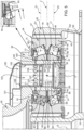
- the transmission 9 further comprises an end stage 20 essentially formed by a planetary gear 21 ( Figure 3 ), which transmits power to the drive shaft 11 of the rotor 5 with the correct torque and angular speed values.
- the planetary gear 21 is a gearbox.
- the planetary gear 21 essentially comprises:
- the crown 17 has a larger diameter than the sun 15.
- the axis B is also coincident with the axis D.
- the crown 17 surrounds the satellite carrier 30.
- the crown 17 is, moreover, carried by a fixed structure only partially shown in the attached Figures.
- the planetary gear 21 further comprises a satellite carrier 30 rotatable around the axis B, directly connected to the drive shaft 11 of the rotor 5, and connected to the satellites 19.
- each satellite 19 rotates around its axis I with respect to the satellite carrier 30 and describes a motion of revolution around the axis B integrally with the satellite carrier 30.
- the mechanical power enters the planetary gear 21 at the sun 15 and exits therefrom, in the direction of the drive shaft 11 of the rotor 5, at the satellite carrier 30, with the correct torque value and number of revolutions.
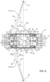
- the satellite carrier 30 comprises, in turn ( Figure 4 ):
- each bearing 40 is adapted to support a respective satellite 19 rotatably around a respective axis I on a respective pin 32.
- the bearing 40 comprises, in turn:
- the bodies 45, 46 are made of steel or ceramic material.
- the rolling bodies 45; 46 are arranged angularly equally spaced with respect to the axis I so as to form two respective crowns 47, 48 axially spaced apart between them.
- the raceway 42 has partially spherical conformation and the rolling bodies 45, 46 are concave and shaped as a conical hourglass.
- Each rolling body 45, 46 is in contact with the raceway 42 at a respective curved line L1, L3 that is open concave on the side of the rolling body 45, 46 ( Figures 5 and 6 ); the line L1, L2 comprising first axial ends 61, 63 opposite one another lying on a straight line R1, R3;
- the straight lines R1; R3 and the axis I define an acute angle ⁇ 1; ⁇ 2 ranging between 10 and 20 degrees, preferably equal to 14 degrees.
- the acute angles ⁇ 1, ⁇ 2; ⁇ 1, ⁇ 2 are equal to each other.
- the points S1, S2 of respective crowns 47, 48 are arranged on opposite axial parts of the bearing 40.
- Each rolling body 45; 46 comprises, in turn:
- each rolling body 45, 46 comprise a plurality of points included between the respective ends 61, 62; 63, 64 and extending at first decreasing and then increasing distances from the respective axis H, proceeding from the respective base 70 towards the respective base 71.
- each rolling body 45; 46 is orthogonal to the axis H and flat.
- each rolling body 45; 46 is shaped as a non-spherical cap generated by the revolution around the relative axis H of a circular segment having its centre on a point K eccentric with respect to the axis H.
- the median planes P1, P2 are equidistant from the lines L1, L2; L3, L4, contain the axis H and the bisectors S1, S2 of the relative rolling body 45, 46 and define a plane of symmetry of the rolling body 45; 46 transverse to the bases 70, 71.
- the ring 41 comprises:
- Each element 51 comprises, in turn:
- the ring 41 comprises, a pair of convex surfaces, axially consecutive between them and defining the raceway 42.
- raceway 42 extends at increasing distances from the axis I from a relative portion 55 of the element 51.
- the raceway 42 is axially interposed between portions 56.
- the raceway 42 extends axially between the portions 56 and at radial distances from the axis I greater than the distance of the portions 55 from the axis I.
- the maximum distance of the raceway 42 from the axis I is lower than the maximum distance of the portions 56 from the axis I.
- the raceway 42 extends symmetrically with respect to an axis J orthogonal to the axis I, in the shown case ( Figure 5 ).
- the raceway 42 has centre O lying on the axes I, J.
- the ring 43 comprises, at a position radially internal with respect to the axis I:
- the element 66 has annular conformation with trapezoidal section tapered towards the axis I, and performs the function of a cage guide exactly like the cage guides 65.
- the cage guides 65 are axially spaced from the bases 70 of the respective rolling bodies 45; 46.
- the shoulders 67 are flat and contact the bases 71 of the respective rolling bodies 45; 46 at respective points K.
- the ring 43 further comprises a pair of convex surfaces radially facing the raceway 42 of the ring 41 and defining respective raceways 44.
- the raceways 44 are axially interposed between relative cage guides 65 and the element 66, in the shown case.
- the ring 43 and the satellite 19 are made in one piece.
- the raceways 42, 44 contact the lateral surfaces 72 ( Figure 7 ) of the relative rolling bodies 45 (46) at the relative closed lines L1 (L2), L3 (L4).
- Each rolling body 45, 46 comprises a respective centre Q1, Q2 arranged on the axis H and equidistant parallel to the axis H from the intersection of the axis H with the respective bases 70, 71.
- the centres Q1, Q2 define respective planes Z1, Z2 parallel to each other and orthogonal to the axis I.
- the bearing 40 further comprises a cage 90 adapted to keep the rolling bodies 45, 46 of relative crowns 47, 48 separated around the axis I.
- the cage 90 is shaped as a ring with a rectangular section in a plane containing the axis I.
- the cage 90 comprises a plurality of through alveoli 91 having a conformation corresponding to that of the rolling bodies 45; 46.
- the alveoli 91 form two groups axially superimposed between them.
- the alveoli 91 of each group are angularly equally spaced between them around the axis I.
- each alveolus 91 is shaped to ensure some clearance with respect to the relative rolling body 45; 46.
- the cage 90 is made of steel and/or the alveoli 91 are made by milling.
- a second embodiment of the cage 90 is indicated with 90'.
- the cage 90' is similar to the cage 90 and is described below only insofar as it differs from it; similar or equal parts of the cages 90, 90' will be referred to by the same reference numbers.
- the cage 90' differs from the cage 90 in that it is shaped as a spherical segment with centre O.
- the cage 90' is, moreover, made in two pieces symmetrical with respect to the axis J.
- the cage 90' is guided only on the raceway 42.
- the cage guides 65 and the element 66 define respective guide surfaces for the cage 90 so as to keep the centre of gravity of the cage 90 as close to the axis I as possible.
- the bearing 40 defines a chamber 85 ( Figure 5 ) radially bounded by the ring 43 and by the ring 41 and within which the rolling bodies 45, 46 roll.
- the planetary gear 21 further comprises a lubrication system 120 of the rolling bodies 45, 46.
- the lubrication system 120 comprises:
- the rolling bearings 45, 46 are interposed along the respective axes I between the sleeve 121 and the environment 122.
- the conveying circuit 123 comprises, in turn, for each bearing 40:
- the seats 145 are provided for the turning and grinding tailstock.
- the openings 127 are angularly equally spaced between them around the axis I.
- the openings 127 are in this configuration axially spaced apart from the openings 128 and the openings 129.
- the holes 130, 140 (141, 142) are angularly equally spaced between them around the axis I.
- the holes 140 are axially spaced apart from the holes 141, which are axially spaced apart from the holes 142.
- the holes 140, 141, 142 lie in respective planes parallel to each other and orthogonal to the axis I of the respective pin 32.
- the bottom 124 is located, in the case in Figure 5 , axially interposed between the holes 140 and 141, 142.
- the bearing 40 further comprises a seal 91 radially interposed between the element 50 of the ring 41 adjacent to the sleeve 121 and the corresponding cage guide 65 of the ring 43.
- the seal 91 is adapted to retain the lubricating fluid in the chamber 85 ( Figure 5 ) .
- the seal 91 and the element 50 have respective end edges 93, 94 facing each other and shaped as portions of spherical surfaces concentric to the raceway 42.
- the element 125 further comprises:
- the openings 127 are axially spaced apart from the openings 128, 129.
- the holes 130, 131, 132 are axially spaced apart between them.
- the bottom 124 of the element 125 is arranged on the side of the axially opposite wall of the holes 132 with respect to the holes 130, 131.
- each bearing 40 further comprises a seal 92 axially opposite to the seal 91, radially interposed between the element 50 of the ring 41 adjacent to the environment 92 and the corresponding cage guide 65 of the ring 43.
- the seal 92 is adapted to retain the lubricating fluid in the chamber 85.
- the seal 92 and the element 50 adjacent to the environment 92 are shaped in the same manner as the seal 91 and the element 50 adjacent to the sleeve 121.
- the transmission 9 transmits motion from the turbines 10 to the drive shaft 11 of the relative rotor 5.
- the power enters the planetary gear 21 through the sun 15, which rotates around the axis D and exits through the satellite carrier 30 connected to the aforesaid drive shaft 11 of the rotor 5.
- the rotation of the sun 15 causes the rotation of the satellites 19 around their axes I and the revolution of the satellites 19 around the axis D.
- the satellites 19 rotate around the relative axes I with respect to the corresponding pins 32 thanks to the bearings 40.
- the rolling bodies 45, 46 allow the rotation of the satellites 19 with respect to the pins 32 around the relative axes I.
- the satellites 19 describe the motion of revolution around the axes B, D integrally with the satellite carrier 30.
- the rotation of the satellite carrier 30 transmits power with the appropriate number of revolutions to the drive shaft 11 of the rotor 5.
- the operation of the planetary gear 21 is described below limited to a single bearing 40, the relative satellite 19 and the relative pin 32.
- the shoulders 67 axially contact the bases 71 of the rolling bodies 45; 46 at respective points K.
- the torque transmitted by the sun 15 causes the deflection of the axis I of the pin 32 with respect to the axis D of the sun 15. This deflection causes the ring 41 to deflect, but does not affect the position of the rolling bodies 45, 46 due to the fact that the raceway 42 is shaped as a spherical surface of centre O.
- the rolling bodies 45, 46 further roll on the respective raceways 42, 44 substantially without sliding.
- the planes Z1, Z2 defined by the centres Q1, Q2 of the rolling bodies 45, 46 remain parallel and orthogonal to the axis I, during the transmission of torque from the sun 15 to the satellite carrier 30.
- the lubricating oil flows from the sleeve 121 into the element 125 through the opening 126.
- the lubricating oil crosses the openings 127, the holes 130 of the pin 32 and the holes 140 of the ring 41 until it reaches the chamber 85.
- the lubricating oil flows between the rolling bodies 45, 46 and lubricates the bearing 40.
- the lubricating oil is retained within the chamber 85 by the seal 91 and reaches the environment 122 via the opening 150.
- the lubricating oil flows from the element 125 to the chamber 85 also through the fluidic paths defined by the:
- the lubricating oil remains, moreover, trapped in the chamber 85 by the presence of the seals 91, 92.
- each rolling bearing 40 is concave, shaped as an hourglass, and are in contact with the raceway 42 (44) at the curved line L1, L2 (L3, L4).
- the straight lines R1, R2 (R3, R4) on which the axial ends 61, 62 (63, 64) of the lines L1, L2 (L3, L4) of each rolling body 45, 46 lie converge in a point S1 (S2) lying on the axis H of the rolling body 45, 46 and on the axis I.
- the bisector T1 (T2) of the angle ⁇ 1 ( ⁇ 2) between the straight lines R1, R2 (R3, R4) lies in the plane P1 (P2).
- any sliding of the rolling bodies 45, 46 on the raceways 42, 44 can be substantially reduced. This is because the rolling bodies 45, 46 and the raceways 42, 44 approximate Poinsot cones.
- the planes Z1, Z2 defined by the centres Q1, Q2 of the rolling bodies 45, 46 remain parallel and orthogonal to the axis I, during the transmission of torque from the sun 15 to the satellite carrier 30.
- the cage 90 of each bearing 40 is guided by the cage guides 65 and of the element 66 in its rotation around the relative axis I.
- each rolling body 45, 46 is shaped as a spherical cap generated by the revolution around the respective axis H of a circular segment having a respective centre at the point K in an eccentric position with respect to the aforesaid axis H.
- each rolling body 45, 46 contacts the shoulder 67 at the relative centre at point K.
- the lubrication system 120 ensures that the lubricating oil laps the rolling bodies 45, 46, substantially reducing any risk of seizure.
- the rolling bearing 40 may comprise a single crown 47, 48 of rolling bodies 45, 46.
- the crown 17 of the planetary gear 21 may be rotatable around the axis D with a different angular speed than that of the sun 15.
- the mechanical power could enter the planetary gear 21 at the satellite carrier 30 and exit it, at the sun 15 with the correct torque value and number of revolutions.
- the transmission 9 may comprise two or more planetary gears 21 in series or in parallel with each other.
- the transmission 9 may be at least partially integrated into one of the turbines 10.
- the transmission 9 and the planetary gear 21 could be used in a helicopter or in a heliplane or in an aircraft capable of remote-piloted hovering commonly referred to as a UAV.
Claims (12)
- Engrenage planétaire (21) pour une transmission (9) d'un aéronef (1) capable de vol stationnaire, comprenant :- un soleil (15) rotatif autour d'un premier axe (B) avec une première vitesse angulaire ;- une couronne (17) fixée angulairement par rapport audit premier axe (B) ou rotative autour dudit premier axe (B) avec une deuxième vitesse angulaire différente de ladite première vitesse angulaire ;- au moins deux satellites (19) s'engrenant chacun avec ladite couronne (17) et ledit soleil (15), qui sont rotatifs autour de dits deuxièmes axes (I) respectifs, qui sont pour leur part rotatifs autour dudit premier axe (B) ; et- un porte-satellites (30) rotatif autour dudit premier axe (B) et comprenant au moins deux premières goupilles (32) par rapport auxquelles lesdits satellites (19) sont rotatifs autour desdits deuxièmes axes (I) respectifs ; et- une pluralité de roulements à rouleaux (40) interposés chacun entre une goupille (32) respective et un satellite (19) respectif de sorte à permettre leur rotation relative autour du deuxième axe (I) respectif ;lesdits roulements (40) comprenant chacun pour leur part :- une première bague (41) solidaire angulairement de ladite goupille (32) et définissant un premier chemin de roulement (42) qui est au moins partiellement sphérique ;- une deuxième bague (43) solidaire angulairement dudit satellite (19) respectif et définissant un deuxième chemin de roulement (44) ; et- une pluralité de corps roulants (45 ; 46), interposés radialement entre ladite première et ladite deuxième bague (41, 43) et roulant, en cours d'utilisation, sur lesdits premier et deuxième chemins de roulement (42, 44) ;caractérisé en ce que :- lesdits corps roulants (45 ; 46) sont concaves et en forme de sablier conique ;chaque dit corps roulant (45 ; 46) étant en contact avec ledit premier chemin de roulement (42) au niveau d'une première ligne incurvée et convexe (L1 ; L3) sur le côté du corps roulant (45, 46) ; ladite première ligne (L1 ; L3) comprenant de premières extrémités axiales (61 ; 63) qui sont opposées l'une à l'autre et se trouvant sur une première ligne droite (Rl ; R3) ;chaque dit corps roulant (45 ; 46) étant en contact avec ledit deuxième chemin de roulement (44) au niveau d'une deuxième ligne incurvée et convexe (42 ; 44) sur le côté du corps roulant (45 ; 46) ; ladite deuxième ligne incurvée (42 ; 44) comprenant des deuxièmes extrémités axiales (62 ; 64) qui sont opposées l'une à l'autre et se trouvant sur une deuxième ligne droite (R2 ; R4) ;lesdites première et deuxième lignes droites (Rl, R3 ; R2, R4) étant inclinées entre elles et convergeant en un premier point (SI ; S2) se trouvant sur un troisième axe (H) dudit corps roulant (45 ; 46) et sur ledit deuxième axe (I) ;lesdites première et deuxième lignes droites (Rl, R3 ; R2, R4) définissant un premier angle (al ; a2), dont la bissectrice (Tl ; T2) se trouve sur ledit troisième axe (H) ;ledit engrenage planétaire (21) comprenant en outre :- un élément annulaire (121) pour collecter un fluide lubrifiant destiné à lubrifier lesdits corps roulants (45 ; 46) desdits roulements (45) d'au moins deux dits satellites (19) et agencé sur un premier côté par rapport audit roulement à rouleaux (40) ; et- des moyens d'acheminement dudit fluide lubrifiant (123) adaptés pour acheminer ledit fluide lubrifiant en contact avec lesdits corps roulants (45 ; 46) ; ladite première bague (41), ladite deuxième bague (43) et lesdits corps roulants (45 ; 46) de chaque dit roulement à rouleaux (40) définissant une chambre (85) qui peut être traversée par ledit fluide lubrifiant ;ladite chambre (85) étant reliée fluidiquement audit élément annulaire (121) ;ledit moyen d'acheminement (123) comprenant, pour chaque dit satellite (19), un élément de collecte (125) logé à l'intérieur de la goupille (32) relative et en communication fluidique avec ledit élément annulaire (121) et ladite chambre (85) ;ledit élément de collecte (125) comprenant une pluralité de premières ouvertures circonférentielles et traversantes (127) qui peuvent être traversées, en cours d'utilisation, par ledit fluide lubrifiant ;ladite goupille (32) comprenant une pluralité de premiers trous radiaux (130) agencés au niveau desdites premières ouvertures (127) dudit élément de collecte (125) et en communication fluidique avec celles-ci ;ladite première bague (41) comprenant une pluralité de deuxièmes trous radiaux (140) en communication fluidique avec ladite chambre (85) et avec lesdits premiers trous (130).
- Engrenage planétaire selon la revendication 1, caractérisé en ce que ledit deuxième axe (I) et ladite première ligne droite (R1 ; R3) définissent un deuxième angle aigu (βl ; β2) allant de 10 à 20 degrés, de préférence égal à 14 degrés.
- Engrenage planétaire selon la revendication 1 ou 2, caractérisé en ce que ledit roulement à rouleaux (40) comprend une première et une deuxième couronne (47, 48) formées respectivement par lesdits premier et deuxième corps tournants (45 ; 46) qui sont espacés angulairement autour dudit deuxième axe (I) respectif ;lesdites couronnes (47, 48) étant étagées axialement par rapport audit deuxième axe (I) ;lesdits premiers points (S1 ; S2) étant agencés sur des côtés respectifs dudit roulement à rouleaux (40) qui sont axialement opposés l'un à l'autre.
- Engrenage planétaire selon la revendication 3, caractérisé en ce que ladite deuxième bague (43) de chaque roulement à rouleaux (40) comprend :- un premier et un deuxième élément (65, 66) adaptés pour guider une cage (90) pour l'écartement desdits corps roulants (45 ; 46) ; et- un épaulement (66, 67) interposé axialement entre lesdits premier et deuxième éléments (65) et adapté pour coopérer axialement avec des extrémités axiales (71) qui sont opposées auxdits premier et deuxième éléments (65, 66) des premier et deuxième corps roulants (45 ; 46) respectifs des première et deuxième couronnes (47, 48) respectives.
- Engrenage planétaire selon la revendication 4, caractérisé en ce que lesdites extrémités axiales (71) de chaque dit corps roulant (45 ; 46) entrent en contact avec ledit épaulement (66, 67) en un au moins un deuxième point (K) respectif qui est excentrique par rapport audit troisième axe (H) respectif ; et/ou
caractérisé en ce que lesdites extrémités axiales (71) sont sous la forme de capuchons asphériques générés par la révolution autour dudit troisième axe (H) d'un segment circulaire ayant son centre sur ledit deuxième point (K) respectif qui est excentrique par rapport audit troisième axe (H) respectif. - Engrenage planétaire selon la revendication 5, caractérisé en ce que ledit épaulement (66, 67) de chaque dite deuxième bague (43) présente une conformation en anneau avec une section trapézoïdale effilée vers ladite première bague (41).
- Engrenage planétaire selon l'une quelconque des revendications 3 à 6, caractérisé en ce que lesdits premier et deuxième corps roulants (45 ; 46) de chaque dit roulement à rouleaux (40) comprennent des quatrièmes axes (J) respectifs ; chacun desdits premier et deuxième corps roulants comprenant un premier et un deuxième centre (QI, Q2) respectifs se trouvant sur ledit quatrième axe (J) respectif et équidistants desdites première et deuxième extrémités axiales (70, 71) le long dudit quatrième axe (J) relatif ;
lesdits premier et deuxième centres (QI, Q2) définissant respectivement un deuxième et un troisième plan (Zl, Z2) qui sont agencés, en cours d'utilisation, de manière parallèle l'un à l'autre et de manière orthogonale audit deuxième axe (I) du satellite (19) relatif. - Engrenage planétaire selon l'une quelconque des revendications 4 à 7, caractérisé en ce que ladite cage (90) est agencée en butée contre lesdits premier et deuxième élément de guidage de cage (65, 66) et l'épaulement (67) dudit roulement à rouleaux (40) relatif.
- Engrenage planétaire selon la revendication 8, caractérisé en ce que ladite première bague (41) comprend :- une paire de premiers éléments d'extrémité axiaux (51) ; et- un deuxième élément (50) interposé axialement entre lesdits premiers éléments (50) et définissant ledit premier chemin de roulement (42) ;lesdits deuxièmes trous (140) étant définis par au moins un desdits éléments d'extrémité axiaux (50) de ladite première bague (41).
- Engrenage planétaire selon la revendication 9, caractérisé en ce qu'il comprend un premier élément d'étanchéité (91) adapté pour isoler de manière étanche aux fluides ladite chambre (85), fixé à ladite deuxième bague (43) et faisant face audit au moins un desdits premiers éléments d'extrémité axiaux (51) de ladite première bague (41).
- Engrenage planétaire selon l'une quelconque des revendications 7 à 10, caractérisé en ce que :ledit élément de collecte (125) comprend une pluralité de deuxièmes ouvertures circonférentielles et traversantes (128, 129) qui peuvent être traversées, en cours d'utilisation, par ledit fluide lubrifiant ; lesdites deuxièmes ouvertures (128, 129) étant étagées axialement sur lesdites premières ouvertures (127) ;ladite goupille (32) comprenant une pluralité de troisièmes trous radiaux traversants (131, 132) agencés au niveau desdites deuxièmes ouvertures (128, 129) dudit élément de collecte (125) et en communication fluidique avec celles-ci ; lesdits premier et troisième trous (130 ; 131, 132) étant étagés axialement entre eux ;ledit premier chemin de roulement (42) de ladite première bague (41) comprenant une pluralité de quatrièmes trous radiaux et traversants (141, 142) en communication fluidique avec ladite chambre (85) et avec lesdits troisièmes trous (131, 132) ;ledit engrenage planétaire (21), comprenant en outre un deuxième élément d'étanchéité (92) adapté pour isoler de manière étanche aux fluides ladite chambre (85), fixé à ladite deuxième bague (43) et faisant face à l'autre desdits éléments d'extrémité axiaux (50) de ladite première bague (41).
- Aéronef (1) capable de vol stationnaire, comprenant :- un organe moteur (10) ;- au moins un rotor (5) relié opérationnellement audit organe moteur (10) ;- au moins un arbre d'entraînement (11, 4) rotatif autour dudit premier axe (B) et adapté pour entraîner ledit rotor (5) ;au moins une transmission (9) interposée entre ledit organe moteur (10) et ledit rotor (5) ; et- un engrenage planétaire (21) selon l'une quelconque des revendications précédentes ;ledit aéronef (1) étant un avion convertible ou un hélicoptère ou un héliplane ;ledit avion convertible comprenant, à son tour, une paire desdits éléments moteurs (10), une paire desdits rotors (5) et une paire desdites transmissions (9) chacune interposée entre un organe moteur (10) respectif et un rotor (5) respectif.
Priority Applications (1)
| Application Number | Priority Date | Filing Date | Title |
|---|---|---|---|
| EP21205733.5A EP4063678B1 (fr) | 2021-03-24 | 2021-03-24 | Engrenage planétaire pour une transmission d'un aéronef capable de vol stationnaire |
Applications Claiming Priority (2)
| Application Number | Priority Date | Filing Date | Title |
|---|---|---|---|
| EP21164529.6A EP4063267B1 (fr) | 2021-03-24 | 2021-03-24 | Engrenage planétaire pour une transmission destinée à un aéronef capable de voler en stationnaire |
| EP21205733.5A EP4063678B1 (fr) | 2021-03-24 | 2021-03-24 | Engrenage planétaire pour une transmission d'un aéronef capable de vol stationnaire |
Related Parent Applications (2)
| Application Number | Title | Priority Date | Filing Date |
|---|---|---|---|
| EP21164529.6A Division EP4063267B1 (fr) | 2021-03-24 | 2021-03-24 | Engrenage planétaire pour une transmission destinée à un aéronef capable de voler en stationnaire |
| EP21164529.6A Division-Into EP4063267B1 (fr) | 2021-03-24 | 2021-03-24 | Engrenage planétaire pour une transmission destinée à un aéronef capable de voler en stationnaire |
Publications (2)
| Publication Number | Publication Date |
|---|---|
| EP4063678A1 EP4063678A1 (fr) | 2022-09-28 |
| EP4063678B1 true EP4063678B1 (fr) | 2023-06-28 |
Family
ID=75977565
Family Applications (3)
| Application Number | Title | Priority Date | Filing Date |
|---|---|---|---|
| EP21205731.9A Active EP4063694B1 (fr) | 2021-03-24 | 2021-03-24 | Engrenage planétaire pour une transmission d'un aéronef capable de vol stationnaire |
| EP21164529.6A Active EP4063267B1 (fr) | 2021-03-24 | 2021-03-24 | Engrenage planétaire pour une transmission destinée à un aéronef capable de voler en stationnaire |
| EP21205733.5A Active EP4063678B1 (fr) | 2021-03-24 | 2021-03-24 | Engrenage planétaire pour une transmission d'un aéronef capable de vol stationnaire |
Family Applications Before (2)
| Application Number | Title | Priority Date | Filing Date |
|---|---|---|---|
| EP21205731.9A Active EP4063694B1 (fr) | 2021-03-24 | 2021-03-24 | Engrenage planétaire pour une transmission d'un aéronef capable de vol stationnaire |
| EP21164529.6A Active EP4063267B1 (fr) | 2021-03-24 | 2021-03-24 | Engrenage planétaire pour une transmission destinée à un aéronef capable de voler en stationnaire |
Country Status (4)
| Country | Link |
|---|---|
| EP (3) | EP4063694B1 (fr) |
| KR (1) | KR20230167378A (fr) |
| CN (1) | CN117083224A (fr) |
| WO (1) | WO2022200853A1 (fr) |
Family Cites Families (12)
| Publication number | Priority date | Publication date | Assignee | Title |
|---|---|---|---|---|
| GB8922563D0 (en) | 1989-10-06 | 1989-11-22 | Rhp Bearings Ltd | Improvements in roller bearings |
| US7471022B2 (en) | 2006-09-22 | 2008-12-30 | Sortore Christopher K | Magnetic bearing |
| US8061903B2 (en) | 2010-01-28 | 2011-11-22 | Rexnord Industries, Llc | Bearing assembly with extended maintenance interval |
| US10077808B2 (en) | 2013-12-18 | 2018-09-18 | Roller Bearing Company Of America, Inc. | Roller profile for hourglass roller bearings in aircraft |
| US9890814B2 (en) | 2014-06-03 | 2018-02-13 | Roller Bearing Company Of America, Inc. | Cage for hourglass roller bearings |
| EP2957781B1 (fr) | 2014-06-03 | 2019-09-25 | Roller Bearing Company of America, Inc. | Support d'un volet à l'arrière de l'aile avec un roulement à rotule sur rouleaux concaves à deux rangées |
| EP3064802A1 (fr) | 2015-03-04 | 2016-09-07 | AGUSTAWESTLAND S.p.A. | Unité de transmission de rotor pour un aéronef capable de vol stationnaire |
| JP6282609B2 (ja) | 2015-03-31 | 2018-02-21 | ミネベアミツミ株式会社 | 転がり軸受 |
| JP6431235B1 (ja) | 2017-06-09 | 2018-11-28 | 株式会社オリジナルボックス | 口金 |
| US11060605B2 (en) | 2018-07-09 | 2021-07-13 | Textron Innovations Inc. | Spherical mounted cylindrical roller bearing system |
| EP3660355B1 (fr) | 2018-11-28 | 2020-12-30 | LEONARDO S.p.A. | Aéronef apte à effectuer un vol stationnaire |
| FR3100223A1 (fr) * | 2019-08-30 | 2021-03-05 | Airbus Helicopters | Boite de transmission de puissance, giravion équipé d’une telle boite de transmission et méthode de variation associée |
-
2021
- 2021-03-24 EP EP21205731.9A patent/EP4063694B1/fr active Active
- 2021-03-24 EP EP21164529.6A patent/EP4063267B1/fr active Active
- 2021-03-24 EP EP21205733.5A patent/EP4063678B1/fr active Active
- 2021-12-20 CN CN202180096269.2A patent/CN117083224A/zh active Pending
- 2021-12-20 KR KR1020237036288A patent/KR20230167378A/ko unknown
- 2021-12-20 WO PCT/IB2021/062033 patent/WO2022200853A1/fr active Application Filing
Also Published As
| Publication number | Publication date |
|---|---|
| EP4063267A1 (fr) | 2022-09-28 |
| EP4063694A1 (fr) | 2022-09-28 |
| EP4063694B1 (fr) | 2023-07-05 |
| EP4063267B1 (fr) | 2024-01-10 |
| KR20230167378A (ko) | 2023-12-08 |
| EP4063678A1 (fr) | 2022-09-28 |
| CN117083224A (zh) | 2023-11-17 |
| WO2022200853A1 (fr) | 2022-09-29 |
Similar Documents
| Publication | Publication Date | Title |
|---|---|---|
| EP3129282B1 (fr) | Systeme de propulsion pour train d'atterrissage d'aeronef | |
| US7607607B2 (en) | De-rotation system suitable for use with a shaft fairing system | |
| EP2711292B1 (fr) | Lubrification de boîte de vitesses | |
| EP2238027B1 (fr) | Joint homocinétique avec différentiel de combinaison de couple | |
| US7871034B2 (en) | Rotor hub systems and methods | |
| US20110299974A1 (en) | Lubricating and cooling epicyclic stepdown gearing | |
| US11370537B2 (en) | Integral flexured carriers for aircraft planetary gear systems | |
| US20220389967A1 (en) | Lubrication system | |
| US11420760B2 (en) | Sealed coaxial input and output shafts | |
| EP3990346B1 (fr) | Rotor anticouple pour hélicoptère | |
| CN113167373B (zh) | 具有悬停能力的飞行器 | |
| EP4063678B1 (fr) | Engrenage planétaire pour une transmission d'un aéronef capable de vol stationnaire | |
| EP3089908B1 (fr) | Appareil du type rotor | |
| US6830215B2 (en) | Pivoting transmission unit with a device to take up play along the pivot axis | |
| KR20210128381A (ko) | 항공기 | |
| EP4056469A1 (fr) | Un aéronef capable de faire du vol stationnaire | |
| US11161606B2 (en) | Flexured standpipes for aircraft propulsion assemblies | |
| US20200018320A1 (en) | Variable pitch fan for a gas turbine engine | |
| US20230373646A1 (en) | Installation of Gear Assemblies in Aircraft Gearboxes | |
| CN108825645A (zh) | 一种滚动轴承系统 | |
| US11493121B2 (en) | Gear systems having bearing flexure mounted thrust bearings |
Legal Events
| Date | Code | Title | Description |
|---|---|---|---|
| PUAI | Public reference made under article 153(3) epc to a published international application that has entered the european phase |
Free format text: ORIGINAL CODE: 0009012 |
|
| STAA | Information on the status of an ep patent application or granted ep patent |
Free format text: STATUS: REQUEST FOR EXAMINATION WAS MADE |
|
| 17P | Request for examination filed |
Effective date: 20220223 |
|
| AC | Divisional application: reference to earlier application |
Ref document number: 4063267 Country of ref document: EP Kind code of ref document: P |
|
| AK | Designated contracting states |
Kind code of ref document: A1 Designated state(s): AL AT BE BG CH CY CZ DE DK EE ES FI FR GB GR HR HU IE IS IT LI LT LU LV MC MK MT NL NO PL PT RO RS SE SI SK SM TR |
|
| RIC1 | Information provided on ipc code assigned before grant |
Ipc: F16H 57/08 20060101ALI20221123BHEP Ipc: F16H 57/04 20100101ALI20221123BHEP Ipc: B64C 27/12 20060101ALI20221123BHEP Ipc: F16C 33/78 20060101ALI20221123BHEP Ipc: F16C 33/58 20060101ALI20221123BHEP Ipc: F16C 33/48 20060101ALI20221123BHEP Ipc: F16C 33/46 20060101ALI20221123BHEP Ipc: F16C 33/30 20060101ALI20221123BHEP Ipc: F16C 33/66 20060101ALI20221123BHEP Ipc: F16C 23/08 20060101ALI20221123BHEP Ipc: F16C 33/36 20060101ALI20221123BHEP Ipc: F16C 19/38 20060101AFI20221123BHEP |
|
| GRAP | Despatch of communication of intention to grant a patent |
Free format text: ORIGINAL CODE: EPIDOSNIGR1 |
|
| STAA | Information on the status of an ep patent application or granted ep patent |
Free format text: STATUS: GRANT OF PATENT IS INTENDED |
|
| INTG | Intention to grant announced |
Effective date: 20230125 |
|
| GRAS | Grant fee paid |
Free format text: ORIGINAL CODE: EPIDOSNIGR3 |
|
| GRAA | (expected) grant |
Free format text: ORIGINAL CODE: 0009210 |
|
| STAA | Information on the status of an ep patent application or granted ep patent |
Free format text: STATUS: THE PATENT HAS BEEN GRANTED |
|
| AC | Divisional application: reference to earlier application |
Ref document number: 4063267 Country of ref document: EP Kind code of ref document: P |
|
| AK | Designated contracting states |
Kind code of ref document: B1 Designated state(s): AL AT BE BG CH CY CZ DE DK EE ES FI FR GB GR HR HU IE IS IT LI LT LU LV MC MK MT NL NO PL PT RO RS SE SI SK SM TR |
|
| REG | Reference to a national code |
Ref country code: CH Ref legal event code: EP |
|
| REG | Reference to a national code |
Ref country code: AT Ref legal event code: REF Ref document number: 1582921 Country of ref document: AT Kind code of ref document: T Effective date: 20230715 |
|
| REG | Reference to a national code |
Ref country code: IE Ref legal event code: FG4D |
|
| REG | Reference to a national code |
Ref country code: DE Ref legal event code: R096 Ref document number: 602021003146 Country of ref document: DE |
|
| REG | Reference to a national code |
Ref country code: LT Ref legal event code: MG9D |
|
| PG25 | Lapsed in a contracting state [announced via postgrant information from national office to epo] |
Ref country code: SE Free format text: LAPSE BECAUSE OF FAILURE TO SUBMIT A TRANSLATION OF THE DESCRIPTION OR TO PAY THE FEE WITHIN THE PRESCRIBED TIME-LIMIT Effective date: 20230628 Ref country code: NO Free format text: LAPSE BECAUSE OF FAILURE TO SUBMIT A TRANSLATION OF THE DESCRIPTION OR TO PAY THE FEE WITHIN THE PRESCRIBED TIME-LIMIT Effective date: 20230928 |
|
| REG | Reference to a national code |
Ref country code: NL Ref legal event code: MP Effective date: 20230628 |
|
| P01 | Opt-out of the competence of the unified patent court (upc) registered |
Effective date: 20231005 |
|
| REG | Reference to a national code |
Ref country code: AT Ref legal event code: MK05 Ref document number: 1582921 Country of ref document: AT Kind code of ref document: T Effective date: 20230628 |
|
| PG25 | Lapsed in a contracting state [announced via postgrant information from national office to epo] |
Ref country code: RS Free format text: LAPSE BECAUSE OF FAILURE TO SUBMIT A TRANSLATION OF THE DESCRIPTION OR TO PAY THE FEE WITHIN THE PRESCRIBED TIME-LIMIT Effective date: 20230628 Ref country code: NL Free format text: LAPSE BECAUSE OF FAILURE TO SUBMIT A TRANSLATION OF THE DESCRIPTION OR TO PAY THE FEE WITHIN THE PRESCRIBED TIME-LIMIT Effective date: 20230628 Ref country code: LV Free format text: LAPSE BECAUSE OF FAILURE TO SUBMIT A TRANSLATION OF THE DESCRIPTION OR TO PAY THE FEE WITHIN THE PRESCRIBED TIME-LIMIT Effective date: 20230628 Ref country code: LT Free format text: LAPSE BECAUSE OF FAILURE TO SUBMIT A TRANSLATION OF THE DESCRIPTION OR TO PAY THE FEE WITHIN THE PRESCRIBED TIME-LIMIT Effective date: 20230628 Ref country code: HR Free format text: LAPSE BECAUSE OF FAILURE TO SUBMIT A TRANSLATION OF THE DESCRIPTION OR TO PAY THE FEE WITHIN THE PRESCRIBED TIME-LIMIT Effective date: 20230628 Ref country code: GR Free format text: LAPSE BECAUSE OF FAILURE TO SUBMIT A TRANSLATION OF THE DESCRIPTION OR TO PAY THE FEE WITHIN THE PRESCRIBED TIME-LIMIT Effective date: 20230929 |
|
| PG25 | Lapsed in a contracting state [announced via postgrant information from national office to epo] |
Ref country code: FI Free format text: LAPSE BECAUSE OF FAILURE TO SUBMIT A TRANSLATION OF THE DESCRIPTION OR TO PAY THE FEE WITHIN THE PRESCRIBED TIME-LIMIT Effective date: 20230628 |
|
| PG25 | Lapsed in a contracting state [announced via postgrant information from national office to epo] |
Ref country code: SK Free format text: LAPSE BECAUSE OF FAILURE TO SUBMIT A TRANSLATION OF THE DESCRIPTION OR TO PAY THE FEE WITHIN THE PRESCRIBED TIME-LIMIT Effective date: 20230628 |
|
| PG25 | Lapsed in a contracting state [announced via postgrant information from national office to epo] |
Ref country code: ES Free format text: LAPSE BECAUSE OF FAILURE TO SUBMIT A TRANSLATION OF THE DESCRIPTION OR TO PAY THE FEE WITHIN THE PRESCRIBED TIME-LIMIT Effective date: 20230628 |
|
| PG25 | Lapsed in a contracting state [announced via postgrant information from national office to epo] |
Ref country code: IS Free format text: LAPSE BECAUSE OF FAILURE TO SUBMIT A TRANSLATION OF THE DESCRIPTION OR TO PAY THE FEE WITHIN THE PRESCRIBED TIME-LIMIT Effective date: 20231028 |
|
| PG25 | Lapsed in a contracting state [announced via postgrant information from national office to epo] |
Ref country code: SM Free format text: LAPSE BECAUSE OF FAILURE TO SUBMIT A TRANSLATION OF THE DESCRIPTION OR TO PAY THE FEE WITHIN THE PRESCRIBED TIME-LIMIT Effective date: 20230628 Ref country code: SK Free format text: LAPSE BECAUSE OF FAILURE TO SUBMIT A TRANSLATION OF THE DESCRIPTION OR TO PAY THE FEE WITHIN THE PRESCRIBED TIME-LIMIT Effective date: 20230628 Ref country code: RO Free format text: LAPSE BECAUSE OF FAILURE TO SUBMIT A TRANSLATION OF THE DESCRIPTION OR TO PAY THE FEE WITHIN THE PRESCRIBED TIME-LIMIT Effective date: 20230628 Ref country code: PT Free format text: LAPSE BECAUSE OF FAILURE TO SUBMIT A TRANSLATION OF THE DESCRIPTION OR TO PAY THE FEE WITHIN THE PRESCRIBED TIME-LIMIT Effective date: 20231030 Ref country code: IS Free format text: LAPSE BECAUSE OF FAILURE TO SUBMIT A TRANSLATION OF THE DESCRIPTION OR TO PAY THE FEE WITHIN THE PRESCRIBED TIME-LIMIT Effective date: 20231028 Ref country code: ES Free format text: LAPSE BECAUSE OF FAILURE TO SUBMIT A TRANSLATION OF THE DESCRIPTION OR TO PAY THE FEE WITHIN THE PRESCRIBED TIME-LIMIT Effective date: 20230628 Ref country code: EE Free format text: LAPSE BECAUSE OF FAILURE TO SUBMIT A TRANSLATION OF THE DESCRIPTION OR TO PAY THE FEE WITHIN THE PRESCRIBED TIME-LIMIT Effective date: 20230628 Ref country code: CZ Free format text: LAPSE BECAUSE OF FAILURE TO SUBMIT A TRANSLATION OF THE DESCRIPTION OR TO PAY THE FEE WITHIN THE PRESCRIBED TIME-LIMIT Effective date: 20230628 Ref country code: AT Free format text: LAPSE BECAUSE OF FAILURE TO SUBMIT A TRANSLATION OF THE DESCRIPTION OR TO PAY THE FEE WITHIN THE PRESCRIBED TIME-LIMIT Effective date: 20230628 |
|
| PG25 | Lapsed in a contracting state [announced via postgrant information from national office to epo] |
Ref country code: PL Free format text: LAPSE BECAUSE OF FAILURE TO SUBMIT A TRANSLATION OF THE DESCRIPTION OR TO PAY THE FEE WITHIN THE PRESCRIBED TIME-LIMIT Effective date: 20230628 |