EP4063633B1 - Fuel supply system with combined metering and shutoff valve - Google Patents
Fuel supply system with combined metering and shutoff valve Download PDFInfo
- Publication number
- EP4063633B1 EP4063633B1 EP22163308.4A EP22163308A EP4063633B1 EP 4063633 B1 EP4063633 B1 EP 4063633B1 EP 22163308 A EP22163308 A EP 22163308A EP 4063633 B1 EP4063633 B1 EP 4063633B1
- Authority
- EP
- European Patent Office
- Prior art keywords
- metering valve
- valve
- spool
- fuel
- gas turbine
- Prior art date
- Legal status (The legal status is an assumption and is not a legal conclusion. Google has not performed a legal analysis and makes no representation as to the accuracy of the status listed.)
- Active
Links
Images


Classifications
-
- F—MECHANICAL ENGINEERING; LIGHTING; HEATING; WEAPONS; BLASTING
- F02—COMBUSTION ENGINES; HOT-GAS OR COMBUSTION-PRODUCT ENGINE PLANTS
- F02C—GAS-TURBINE PLANTS; AIR INTAKES FOR JET-PROPULSION PLANTS; CONTROLLING FUEL SUPPLY IN AIR-BREATHING JET-PROPULSION PLANTS
- F02C7/00—Features, components parts, details or accessories, not provided for in, or of interest apart form groups F02C1/00 - F02C6/00; Air intakes for jet-propulsion plants
- F02C7/22—Fuel supply systems
- F02C7/232—Fuel valves; Draining valves or systems
-
- F—MECHANICAL ENGINEERING; LIGHTING; HEATING; WEAPONS; BLASTING
- F02—COMBUSTION ENGINES; HOT-GAS OR COMBUSTION-PRODUCT ENGINE PLANTS
- F02C—GAS-TURBINE PLANTS; AIR INTAKES FOR JET-PROPULSION PLANTS; CONTROLLING FUEL SUPPLY IN AIR-BREATHING JET-PROPULSION PLANTS
- F02C7/00—Features, components parts, details or accessories, not provided for in, or of interest apart form groups F02C1/00 - F02C6/00; Air intakes for jet-propulsion plants
- F02C7/22—Fuel supply systems
- F02C7/222—Fuel flow conduits, e.g. manifolds
-
- F—MECHANICAL ENGINEERING; LIGHTING; HEATING; WEAPONS; BLASTING
- F02—COMBUSTION ENGINES; HOT-GAS OR COMBUSTION-PRODUCT ENGINE PLANTS
- F02C—GAS-TURBINE PLANTS; AIR INTAKES FOR JET-PROPULSION PLANTS; CONTROLLING FUEL SUPPLY IN AIR-BREATHING JET-PROPULSION PLANTS
- F02C9/00—Controlling gas-turbine plants; Controlling fuel supply in air- breathing jet-propulsion plants
- F02C9/26—Control of fuel supply
- F02C9/263—Control of fuel supply by means of fuel metering valves
-
- F—MECHANICAL ENGINEERING; LIGHTING; HEATING; WEAPONS; BLASTING
- F05—INDEXING SCHEMES RELATING TO ENGINES OR PUMPS IN VARIOUS SUBCLASSES OF CLASSES F01-F04
- F05D—INDEXING SCHEME FOR ASPECTS RELATING TO NON-POSITIVE-DISPLACEMENT MACHINES OR ENGINES, GAS-TURBINES OR JET-PROPULSION PLANTS
- F05D2240/00—Components
- F05D2240/55—Seals
-
- F—MECHANICAL ENGINEERING; LIGHTING; HEATING; WEAPONS; BLASTING
- F05—INDEXING SCHEMES RELATING TO ENGINES OR PUMPS IN VARIOUS SUBCLASSES OF CLASSES F01-F04
- F05D—INDEXING SCHEME FOR ASPECTS RELATING TO NON-POSITIVE-DISPLACEMENT MACHINES OR ENGINES, GAS-TURBINES OR JET-PROPULSION PLANTS
- F05D2260/00—Function
- F05D2260/60—Fluid transfer
-
- F—MECHANICAL ENGINEERING; LIGHTING; HEATING; WEAPONS; BLASTING
- F05—INDEXING SCHEMES RELATING TO ENGINES OR PUMPS IN VARIOUS SUBCLASSES OF CLASSES F01-F04
- F05D—INDEXING SCHEME FOR ASPECTS RELATING TO NON-POSITIVE-DISPLACEMENT MACHINES OR ENGINES, GAS-TURBINES OR JET-PROPULSION PLANTS
- F05D2270/00—Control
- F05D2270/30—Control parameters, e.g. input parameters
- F05D2270/301—Pressure
- F05D2270/3015—Pressure differential pressure
-
- F—MECHANICAL ENGINEERING; LIGHTING; HEATING; WEAPONS; BLASTING
- F05—INDEXING SCHEMES RELATING TO ENGINES OR PUMPS IN VARIOUS SUBCLASSES OF CLASSES F01-F04
- F05D—INDEXING SCHEME FOR ASPECTS RELATING TO NON-POSITIVE-DISPLACEMENT MACHINES OR ENGINES, GAS-TURBINES OR JET-PROPULSION PLANTS
- F05D2270/00—Control
- F05D2270/50—Control logic embodiments
- F05D2270/56—Control logic embodiments by hydraulic means, e.g. hydraulic valves within a hydraulic circuit
-
- F—MECHANICAL ENGINEERING; LIGHTING; HEATING; WEAPONS; BLASTING
- F05—INDEXING SCHEMES RELATING TO ENGINES OR PUMPS IN VARIOUS SUBCLASSES OF CLASSES F01-F04
- F05D—INDEXING SCHEME FOR ASPECTS RELATING TO NON-POSITIVE-DISPLACEMENT MACHINES OR ENGINES, GAS-TURBINES OR JET-PROPULSION PLANTS
- F05D2270/00—Control
- F05D2270/60—Control system actuates means
- F05D2270/62—Electrical actuators
Definitions
- This application relates to valving for use in a fuel supply system for a gas turbine engine.
- Gas turbine engines are known, and typically include a fan delivering air into a compressor where it is compressed and delivered into a combustor.
- the compressed air is mixed with fuel in the combustor and ignited. Products of this combustion pass downstream over turbine rotors, driving them to rotate.
- the turbine rotors drive fan and compressor rotors.
- a fuel supply system for supplying fuel to the combustor must deliver an accurate volume of fuel, and at a desired pressure.
- fuel supply systems including a fuel tank with a pump delivering fuel through a metering valve.
- the metering valve is controlled by an engine control to provide a desired volume of fuel to the combustor dependent on the needs of the engine.
- EP 1 557 546 B1 describes a fuel supply system.
- EP 1 715 161 B1 describes a fuel system.
- US 7,413,141 B 1 describes a gas turbine engine fuel control system.
- a fuel supply system includes a metering valve to be connected to a fuel pump.
- the metering valve includes a metering valve spool which is movable to control a volume of fuel passing through the metering valve.
- the metering valve has an extension chamber and a retraction chamber on opposed sides of a land on the spool.
- the extension and retraction chambers communicate with a servo valve to communicate a pressure fluid and a dump connection to one of the extension and retraction chambers to extend or retract the metering valve spool.
- a forward valve spool face is on an axially forward side of the metering valve spool.
- the line to connect the metering valve to the pump has a connection through a metering valve housing which extends into a metering valve inlet chamber, providing a force against the forward face of the metering valve spool.
- a seal is provided such that the forward face of the metering valve spool may seal against the seal in the metering valve housing to block flow into the metering valve inlet chamber.
- a line extends through the valve spool housing from the chamber to a pressure regulating valve.
- the pressure regulating valve is downstream of the metering valve and has a pressure regulative valve spool having opposed faces.
- a line downstream of the pressure regulating valve is to be connected to a combustor.
- a control controls a position of the metering valve spool, and selectively moves the metering valve spool to control a volume of fuel delivered from the chamber to the pressure regulating valve.
- the control is programmed to selectively move the metering valve spool to a position where the forward face of the metering valve spool seals on the seal in the metering valve housing to block flow from the centrifugal pump from reaching the pressure regulating valve, and also from reaching the tap.
- Prior art fuel supply system 20 as illustrated in Figure 1 includes a fuel tank 22 delivering fuel to a centrifugal pump 24.
- the pump 24 supplies fuel to a metering valve 26.
- Metering valve 26 has a spool 36 with its position controlled by an electrohydraulic servo valve 28.
- Valve 28 selectively supplies a high pressure fluid 30 and a low pressure fluid 32 to opposed sides of the spool 36.
- the low pressure fluid 32 is connected to a sump, and the high pressure fluid 30 is connected to a pump such as a hydraulic pump.
- a line 40 communicates one of the lines 30 and 32 to a chamber 38 on one side of the spool 36, and the other line 42 to the opposed side 44 of the spool 36.
- a position transducer 45 communicates a position of the spool 36 to a control 90.
- the control 90 may be a full authority digital electronic controller for an associated gas turbine engine, and is programmed to control the valve 28 to achieve a desired fuel flow dependent on the needs of the engine. Alternatively, a stand alone control may be used.
- a chamber 48 is formed in an outer peripheral surface of the spool 36 and selectively communicates a line 47 downstream of the pump 24 to a chamber 50, and a line 52 heading to a pressure regulating valve 54.
- the line 52 passes into a chamber 53 in a housing, and then into a line 57 heading downstream of the pressure regulating valve 54.
- a spool 56 in pressure regulating valve 54 receives a tap 58 from chamber 48 of the metering valve spool 36 which is equal to the pressure downstream of the pump 24.
- the pressure regulating spool 56 is moved to selectively achieve a desired pressure difference between the pressure on line 52 downstream of the metering valve 26 and the pressure on line 58 upstream of the spool valve 26.
- shutoff valve 64 Downstream of the spool 54 the fuel reaches a line 57 and heads to a shutoff valve 64.
- Shutoff valve 64 has a spool 66 biased by a spring 70, and the pressure 68 which is at a low pressure relative to the pressure on line 62.
- chamber 48 When the metering valve closes (moves upwardly in the Figure 1 position) chamber 48 provides two functions. First, it closes off a connection to chamber 50, which reduces the flow sent to the pressure regulating valve. It also connects to line 68 which closes the shutoff valve to prevent leakage from the metering valve and pressure regulating valve from reaching the combustor. If the shutoff valve 66 does not block flow downstream, flow will pass into a line 72 heading to a combustor 74 of a gas turbine engine.
- a disclosed fuel supply system 100 is illustrated in Figure 2 .
- a fuel tank 101 delivers fuel to a centrifugal pump 102.
- the fuel reaches a metering valve 104, which controls the volume of fluid delivered downstream to a pressure regulating valve 106.
- Pressure regulating valve 106 achieves a desired pressure at a line 108 leading to combustor 110 for a gas turbine engine, similar to the Prior Art valve 54.
- the metering valve 104 under this disclosure also provides the function of a shut off valve, as will be explained.
- a spool 112 is movable within a housing 122 in the metering valve 104.
- the spool 112 has a piston head 115 with a forward face 114 that may seal against a seal 116 in the housing 122.
- a line 118 downstream of the pump 102 communicates fuel into a metering valve inlet chamber 124 forward of the face 114, and then into a valve chamber 126 where it is delivered into a line 128 approaching the pressure regulating valve 106.
- the pressure regulating valve 106 there is a surface 130 in a housing, which may be housing 122, or may be a distinct housing.
- a pressure regulating spool 134 has a forward face 132 that can approach the surface 130 dependent on a pressure difference between the lines 128 and a tap 121.
- Tap 121 provides a connection from metering valve inlet chamber 124 to a chamber 138 on an opposed side of the spool valve 134 from that seen by face 132.
- a spring 136 assists in biasing the spool 134 in a downward position, against the pressure from the line 140.
- a control 152 which may be a full authority digital electronic controller (“FADEC”) or may be a standalone controller is programmed to calculate a desired fuel flow to the combustor 110 based upon standard factors as is known in the art, and dependent on the operational conditions of the gas turbine engine associated with the combustor 110.
- FADEC full authority digital electronic controller
- the control 152 controls an electrohydraulic servo valve 148, which is similar to that shown in Figure 1 , to selectively connect a high pressure line 151 and sump line 153 to a line 150 and 152 to an extension chamber 142 and a retraction chamber 144 on opposed sides of a land 170 on the spool 112.
- a spring 146 acts in conjunction to the pressure in extension chamber 142 to bias the spool 112 to the right as shown in Figure 2 .
- a transducer 149 communicates a position of the spool 112 to the control 152.
- control 152 is programmed to move the spool 112 to a position to achieve a desired volume of fuel flow to the combustor 110 dependent on the operational conditions of the gas turbine engine.
- control 152 is programmed to move the spool valve 112 to the position shown in Figure 3 .
- face 114 seals on seal 116 to block flow downstream of the centrifugal pump 102 from reaching line 128, and also blocking flow of the fuel from reaching tap 121, and line 140.
- the piston head 115 on the metering valve spool 112 has a first diameter and land 170 has a second diameter, larger than the first diameter.
- the piston head 115 is received within a housing portion 117 extending to a forward end.
- the housing portion 117 guides the forward face 114 of the metering valve spool 112 to seat on the seal 116.
- a housing portion 301 (which may be the same, or separate from housing portion 117) includes an o-ring seal 300 to seat on the metering valve spool outer peripheral surface 302. This provides a fluid tight seal between chambers 144 and 126. At shut down this assists in the complete shut off of flow downstream of metering valve 104.
- a fuel supply valving system 100 under this disclosure includes a metering valve 104 to be connected to a fuel pump 102, including a metering valve spool 112 which is movable to control a volume of fuel passing through the metering valve.
- the metering valve has an extension 142 and a retraction chamber 144 on opposed sides of land 170 on the metering valve spool.
- the extension and retraction chambers communicate with a servo valve 148 to communicate a pressure fluid and a dump connection to one of the extension and retraction chambers to extend or retract the metering valve spool.
- the metering valve spool 112 has a valve spool face 114 on a forward side of the valve spool.
- a line 118 to connect the metering valve to the pump has a connection through a metering valve housing which extends into a metering valve inlet chamber 124 providing a force against the forward face of the valve spool.
- a seal 116 is provided such that the forward face of the metering valve spool may seal against the seal to block flow into the chamber.
- a line 128 extends through the metering valve housing from the chamber to a pressure regulating valve.
- the pressure regulating 5 valve is downstream of the metering valve and has a pressure regulating spool 134 having opposed faces.
- the pressure regulating spool 134 has a face that sees that a pressure downstream of the metering valve, and an opposed face of the pressure regulating spool sees a pressure from a tap 121 from the metering valve inlet chamber on an opposed side.
- a line downstream of the pressure regulating valve is to be connected to a combustor 110.
- a control 152 is programmed to control a position of the metering valve spool.
- the control selectively moves the metering valve spool to control a volume of fuel delivered from the chamber 124 to the pressure regulating valve 106.
- the control is programmed to move the metering valve spool to a position where the forward face 114 of the valve spool seals on the seal 116 to block flow from the pump from reaching the line leading to the pressure regulating valve 106 and also from reaching the tap.
Landscapes
- Engineering & Computer Science (AREA)
- Chemical & Material Sciences (AREA)
- Combustion & Propulsion (AREA)
- Mechanical Engineering (AREA)
- General Engineering & Computer Science (AREA)
- Feeding And Controlling Fuel (AREA)
Description
- This application relates to valving for use in a fuel supply system for a gas turbine engine.
- Gas turbine engines are known, and typically include a fan delivering air into a compressor where it is compressed and delivered into a combustor. The compressed air is mixed with fuel in the combustor and ignited. Products of this combustion pass downstream over turbine rotors, driving them to rotate. The turbine rotors drive fan and compressor rotors. As known, a fuel supply system for supplying fuel to the combustor must deliver an accurate volume of fuel, and at a desired pressure. Thus, it is known to have fuel supply systems including a fuel tank with a pump delivering fuel through a metering valve. The metering valve is controlled by an engine control to provide a desired volume of fuel to the combustor dependent on the needs of the engine. Downstream of the metering valve the fuel passes through an in-line pressure regulating valve which maintains a desired fuel pressure drop across the metering valve window. Downstream of the pressure regulating valve there is a shutoff valve which selectively shuts off the supply of fuel downstream of the pressure regulating valve, and before it reaches the combustor in the gas turbine engine.
EP 1 557 546 B1 describes a fuel supply system.EP 1 715 161 B1 describes a fuel system.US 7,413,141 B 1 describes a gas turbine engine fuel control system. - A fuel supply system includes a metering valve to be connected to a fuel pump. The metering valve includes a metering valve spool which is movable to control a volume of fuel passing through the metering valve. The metering valve has an extension chamber and a retraction chamber on opposed sides of a land on the spool. The extension and retraction chambers communicate with a servo valve to communicate a pressure fluid and a dump connection to one of the extension and retraction chambers to extend or retract the metering valve spool. A forward valve spool face is on an axially forward side of the metering valve spool. The line to connect the metering valve to the pump has a connection through a metering valve housing which extends into a metering valve inlet chamber, providing a force against the forward face of the metering valve spool. A seal is provided such that the forward face of the metering valve spool may seal against the seal in the metering valve housing to block flow into the metering valve inlet chamber. A line extends through the valve spool housing from the chamber to a pressure regulating valve. The pressure regulating valve is downstream of the metering valve and has a pressure regulative valve spool having opposed faces. One of the opposed faces sees a pressure downstream of the metering valve, and an opposed valve face of the pressure regulating valve spool sees a pressure from a tap from the metering valve inlet chamber. A line downstream of the pressure regulating valve is to be connected to a combustor. A control controls a position of the metering valve spool, and selectively moves the metering valve spool to control a volume of fuel delivered from the chamber to the pressure regulating valve. The control is programmed to selectively move the metering valve spool to a position where the forward face of the metering valve spool seals on the seal in the metering valve housing to block flow from the centrifugal pump from reaching the pressure regulating valve, and also from reaching the tap.
- These and other features may be best understood from the following drawings and specification, the following is a brief description.
-
-
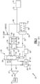
Figure 1 shows a known fuel supply system. -
Figure 2 shows a fuel supply system for a gas turbine engine in a first metering position. -
Figure 3 shows the fuel supply system ofFigure 2 in a shutoff position. - Prior art fuel supply system 20 as illustrated in
Figure 1 includes afuel tank 22 delivering fuel to acentrifugal pump 24. Thepump 24 supplies fuel to ametering valve 26.Metering valve 26 has aspool 36 with its position controlled by anelectrohydraulic servo valve 28. Valve 28 selectively supplies ahigh pressure fluid 30 and alow pressure fluid 32 to opposed sides of thespool 36. Thelow pressure fluid 32 is connected to a sump, and thehigh pressure fluid 30 is connected to a pump such as a hydraulic pump. - A
line 40 communicates one of thelines chamber 38 on one side of thespool 36, and theother line 42 to the opposed side 44 of thespool 36. A position transducer 45 communicates a position of thespool 36 to acontrol 90. - The
control 90 may be a full authority digital electronic controller for an associated gas turbine engine, and is programmed to control thevalve 28 to achieve a desired fuel flow dependent on the needs of the engine. Alternatively, a stand alone control may be used. - A
chamber 48 is formed in an outer peripheral surface of thespool 36 and selectively communicates aline 47 downstream of thepump 24 to achamber 50, and aline 52 heading to apressure regulating valve 54. Theline 52 passes into achamber 53 in a housing, and then into aline 57 heading downstream of thepressure regulating valve 54. Aspool 56 inpressure regulating valve 54 receives atap 58 fromchamber 48 of themetering valve spool 36 which is equal to the pressure downstream of thepump 24. - Thus, the
pressure regulating spool 56 is moved to selectively achieve a desired pressure difference between the pressure online 52 downstream of themetering valve 26 and the pressure online 58 upstream of thespool valve 26. - Downstream of the
spool 54 the fuel reaches aline 57 and heads to a shutoff valve 64. Shutoff valve 64 has aspool 66 biased by aspring 70, and thepressure 68 which is at a low pressure relative to the pressure online 62. - When the metering valve closes (moves upwardly in the
Figure 1 position)chamber 48 provides two functions. First, it closes off a connection tochamber 50, which reduces the flow sent to the pressure regulating valve. It also connects toline 68 which closes the shutoff valve to prevent leakage from the metering valve and pressure regulating valve from reaching the combustor. If theshutoff valve 66 does not block flow downstream, flow will pass into aline 72 heading to acombustor 74 of a gas turbine engine. - A disclosed
fuel supply system 100 is illustrated inFigure 2 . Afuel tank 101 delivers fuel to acentrifugal pump 102. The fuel reaches ametering valve 104, which controls the volume of fluid delivered downstream to apressure regulating valve 106.Pressure regulating valve 106 achieves a desired pressure at aline 108 leading tocombustor 110 for a gas turbine engine, similar to the Prior Artvalve 54. Themetering valve 104 under this disclosure also provides the function of a shut off valve, as will be explained. - A
spool 112 is movable within ahousing 122 in themetering valve 104. Thespool 112 has apiston head 115 with aforward face 114 that may seal against aseal 116 in thehousing 122. - A
line 118 downstream of thepump 102 communicates fuel into a meteringvalve inlet chamber 124 forward of theface 114, and then into avalve chamber 126 where it is delivered into aline 128 approaching thepressure regulating valve 106. There is a pressure drop across themetering valve 104 betweenline 118 andline 128. In thepressure regulating valve 106 there is asurface 130 in a housing, which may be housing 122, or may be a distinct housing. Apressure regulating spool 134 has aforward face 132 that can approach thesurface 130 dependent on a pressure difference between thelines 128 and atap 121.Tap 121 provides a connection from meteringvalve inlet chamber 124 to achamber 138 on an opposed side of thespool valve 134 from that seen byface 132. Aspring 136 assists in biasing thespool 134 in a downward position, against the pressure from theline 140. - A
control 152, which may be a full authority digital electronic controller ("FADEC") or may be a standalone controller is programmed to calculate a desired fuel flow to thecombustor 110 based upon standard factors as is known in the art, and dependent on the operational conditions of the gas turbine engine associated with thecombustor 110. - The
control 152 controls anelectrohydraulic servo valve 148, which is similar to that shown inFigure 1 , to selectively connect ahigh pressure line 151 andsump line 153 to aline extension chamber 142 and aretraction chamber 144 on opposed sides of aland 170 on thespool 112. - A
spring 146 acts in conjunction to the pressure inextension chamber 142 to bias thespool 112 to the right as shown inFigure 2 . Atransducer 149 communicates a position of thespool 112 to thecontrol 152. - Thus, during operation of the gas turbine engine associated with the
combustor 110, thecontrol 152 is programmed to move thespool 112 to a position to achieve a desired volume of fuel flow to thecombustor 110 dependent on the operational conditions of the gas turbine engine. - If it is desirable to stop the flow to the
combustor 110, then thecontrol 152 is programmed to move thespool valve 112 to the position shown inFigure 3 . In the position shown inFigure 3 , face 114 seals onseal 116 to block flow downstream of thecentrifugal pump 102 from reachingline 128, and also blocking flow of the fuel from reachingtap 121, andline 140. - The
piston head 115 on themetering valve spool 112 has a first diameter andland 170 has a second diameter, larger than the first diameter. - The
piston head 115 is received within ahousing portion 117 extending to a forward end. Thehousing portion 117 guides theforward face 114 of themetering valve spool 112 to seat on theseal 116. - A housing portion 301 (which may be the same, or separate from housing portion 117) includes an o-
ring seal 300 to seat on the metering valve spool outerperipheral surface 302. This provides a fluid tight seal betweenchambers metering valve 104. - As such, the
system 100 illustrated inFigures 2 and3 eliminates the requirement of the shutoff valve as has been utilized in the prior art as shown inFigure 1 . - A fuel
supply valving system 100 under this disclosure includes ametering valve 104 to be connected to afuel pump 102, including ametering valve spool 112 which is movable to control a volume of fuel passing through the metering valve. The metering valve has anextension 142 and aretraction chamber 144 on opposed sides ofland 170 on the metering valve spool. The extension and retraction chambers communicate with aservo valve 148 to communicate a pressure fluid and a dump connection to one of the extension and retraction chambers to extend or retract the metering valve spool. - The
metering valve spool 112 has avalve spool face 114 on a forward side of the valve spool. Aline 118 to connect the metering valve to the pump has a connection through a metering valve housing which extends into a meteringvalve inlet chamber 124 providing a force against the forward face of the valve spool. Aseal 116 is provided such that the forward face of the metering valve spool may seal against the seal to block flow into the chamber. Aline 128 extends through the metering valve housing from the chamber to a pressure regulating valve. The pressure regulating 5 valve is downstream of the metering valve and has apressure regulating spool 134 having opposed faces. - The
pressure regulating spool 134 has a face that sees that a pressure downstream of the metering valve, and an opposed face of the pressure regulating spool sees a pressure from atap 121 from the metering valve inlet chamber on an opposed side. A line downstream of the pressure regulating valve is to be connected to acombustor 110. - A
control 152 is programmed to control a position of the metering valve spool. The control selectively moves the metering valve spool to control a volume of fuel delivered from thechamber 124 to thepressure regulating valve 106. The control is programmed to move the metering valve spool to a position where theforward face 114 of the valve spool seals on theseal 116 to block flow from the pump from reaching the line leading to thepressure regulating valve 106 and also from reaching the tap. - Although a specific embodiment has been disclosed, a worker of ordinary skill in this art would recognize that certain modifications could come within the scope of this disclosure. For these reasons, the following claims should be studied to determine the true scope and content of this disclosure.
Claims (10)
- A gas turbine engine comprising:
a fuel tank and a fuel supply system including a fuel pump, the fuel system selectively providing fuel to a combustor in the gas turbine engine, the fuel supply system further including:a metering valve (104) connected to the fuel pump, the metering valve (104) includes a metering valve spool which is movable to control a volume of fuel passing through the metering valve (104);the metering valve (104) has an extension chamber and a retraction chamber on opposed sides of a land on the metering valve spool (112), and the extension chamber and the retraction chamber communicating with a servo valve (148) to communicate a high pressure fluid and a low pressure connection to one of the extension chamber and the retraction chamber to extend or retract the metering valve spool (112);a forward valve spool face on a forward side of the metering valve spool (112), and a pump line (118) connects the metering valve (104) to the pump through a metering valve housing (117),the pump line extends into a metering valve inlet chamber (124) providing a force against the forward valve spool face;a seal (116) is in said metering valve housing such that the forward face of the metering valve spool (112) may seal against the seal (116) in the metering valve housing to block flow into the metering valve inlet chamber;a fuel line extends through the metering valve housing from the metering valve inlet chamber to a pressure regulating valve (106), the pressure regulating valve is downstream of the metering valve (104) and has a pressure regulative spool having opposed faces with one of the opposed faces seeing a pressure from the fuel line downstream of the metering valve (104), and an opposed valve face of the pressure regulating spool seeing a pressure from the metering valve inlet chamber from a tap (121), and a line downstream of the pressure regulating valve to be connected to a combustor; anda controller is programmed for controlling a position of the metering valve spool (112), the controller selectively controls the servo valve to move the metering valve spool (112) to control a volume of fuel delivered from the chamber to the pressure regulating valve, and further being programmed to move the metering valve spool (112) to a position where the forward valve spool face seals on the seal (116) in the metering valve housing to block pump flow reaching the pressure regulating valve, and also reaching the tap. - The gas turbine engine as set forth in claim 1, wherein the controller controlling the servo valve to selectively connect one of the high pressure fluid and low pressure connection to the one of the extension chamber and the retraction chamber.
- The gas turbine engine as set forth in claim 2, wherein a first spring biases the metering valve spool towards the seal (116), and the first spring being opposed by a fluid in the retraction chamber.
- The gas turbine engine as set forth in claim 3, wherein a second spring biases the pressure regulating valve in a direction opposed to a pressure force provided by the tap.
- The gas turbine engine as set forth in claim 4, wherein a transducer provides a metering valve position to the control.
- The gas turbine engine as set forth in claim 5, wherein a piston head on the metering valve spool (112) has a first diameter, and the land has a second diameter, the second diameter being larger than the first diameter.
- The gas turbine engine as set forth in claim 6, wherein the piston head received within a housing portion that extends to a forward end where the forward valve spool face is guided in the housing portion to seat on the seal (116).
- The gas turbine engine as set forth in any of claims 1 to 7, wherein a piston head on the metering valve spool (112) has a first diameter, and the land has a second diameter, the second diameter being larger than the first diameter.
- The gas turbine engine as set forth in claim 8, wherein the piston head received within a housing portion extending to a forward end where the forward valve spool face is guided in the housing portion to seat on the seal (116).
- The gas turbine engine as set forth in any of claims 1 to 9, wherein a housing portion receive an o-ring to seat on an outer peripheral surface of said piston head.
Applications Claiming Priority (1)
| Application Number | Priority Date | Filing Date | Title |
|---|---|---|---|
| US17/213,685 US11421600B1 (en) | 2021-03-26 | 2021-03-26 | Fuel supply system with combined metering and shutoff valve |
Publications (2)
| Publication Number | Publication Date |
|---|---|
| EP4063633A1 EP4063633A1 (en) | 2022-09-28 |
| EP4063633B1 true EP4063633B1 (en) | 2024-08-28 |
Family
ID=80928988
Family Applications (1)
| Application Number | Title | Priority Date | Filing Date |
|---|---|---|---|
| EP22163308.4A Active EP4063633B1 (en) | 2021-03-26 | 2022-03-21 | Fuel supply system with combined metering and shutoff valve |
Country Status (2)
| Country | Link |
|---|---|
| US (1) | US11421600B1 (en) |
| EP (1) | EP4063633B1 (en) |
Families Citing this family (10)
| Publication number | Priority date | Publication date | Assignee | Title |
|---|---|---|---|---|
| US12454915B2 (en) | 2022-08-26 | 2025-10-28 | Hamilton Sundstrand Corporation | Force modification of passive valve spools for control of nozzles |
| US12286931B2 (en) | 2022-08-26 | 2025-04-29 | Collins Engine Nozzles, Inc. | Variable restriction of a fuel circuit of a fuel nozzle |
| US11970977B2 (en) * | 2022-08-26 | 2024-04-30 | Hamilton Sundstrand Corporation | Variable restriction of a secondary circuit of a fuel injector |
| US12270343B2 (en) | 2022-08-26 | 2025-04-08 | Collins Engine Nozzles, Inc. | Proportional restriction of fuel nozzle with an auxiliary circuit |
| US12313004B2 (en) | 2022-08-26 | 2025-05-27 | Collins Engine Nozzles, Inc. | Proportional force modification of passive spool for control of secondary nozzle circuits |
| US11913381B1 (en) | 2022-08-26 | 2024-02-27 | Hamilton Sundstrand Corporation | Force modification of passive spool for control of secondary nozzle circuits |
| US12305581B2 (en) | 2022-08-26 | 2025-05-20 | Collins Engine Nozzles, Inc. | Proportional restriction of a secondary circuit of a fuel injector |
| US11970976B2 (en) * | 2022-08-26 | 2024-04-30 | Hamilton Sundstrand Corporation | Variable restriction of fuel nozzle with an auxiliary circuit |
| US11913382B1 (en) | 2022-08-26 | 2024-02-27 | Hamilton Sundstrand Corporation | Variable restriction of a fuel circuit of a fuel nozzle |
| CN116734173B (en) * | 2023-06-15 | 2025-11-11 | 苏州亨利通信材料有限公司 | Multi-component material conveying control valve group and conveying method |
Family Cites Families (18)
| Publication number | Priority date | Publication date | Assignee | Title |
|---|---|---|---|---|
| GB630325A (en) | 1945-11-24 | 1949-10-11 | British Thomson Houston Co Ltd | Improved combined shut-off and metering valve |
| US2485349A (en) | 1945-11-24 | 1949-10-18 | Gen Electric | Combined shutoff and metering valve |
| GB644324A (en) | 1946-07-10 | 1950-10-11 | British Thomson Houston Co Ltd | Improvements in and relating to combined shut-off and metering valves |
| US2510617A (en) | 1946-07-10 | 1950-06-06 | Gen Electric | Combined shutoff and metering valve |
| GB8910701D0 (en) * | 1989-05-10 | 2006-09-20 | Lucas Ind Plc | Gas turbine engine fuel control system and regulating valves therefore |
| US5118075A (en) | 1991-02-12 | 1992-06-02 | Allied-Signal Inc. | Seal arrangement for a metering valve |
| US6250894B1 (en) * | 1999-04-07 | 2001-06-26 | United Technologies Corporation | Load sharing valve and system for operating centrifugal pumps in parallel |
| US6619027B1 (en) * | 2000-10-13 | 2003-09-16 | General Electric Company | Gas turbine having rotor overspeed and overboost protection |
| US7007452B1 (en) * | 2003-06-13 | 2006-03-07 | Woodward Governor Company | Fuel system for a gas turbine engine |
| US7273068B2 (en) | 2004-01-14 | 2007-09-25 | Honeywell International, Inc. | Electric driven, integrated metering and shutoff valve for fluid flow control |
| GB0401207D0 (en) * | 2004-01-21 | 2004-02-25 | Goodrich Control Sys Ltd | Fuel supply system |
| GB0508126D0 (en) * | 2005-04-22 | 2005-06-01 | Goodrich Control Sys Ltd | Fuel system |
| US8104258B1 (en) | 2007-05-24 | 2012-01-31 | Jansen's Aircraft Systems Controls, Inc. | Fuel control system with metering purge valve for dual fuel turbine |
| US7966994B2 (en) * | 2008-08-12 | 2011-06-28 | Woodcard, Inc. | System for metering a fuel supply |
| GB0922349D0 (en) * | 2009-12-22 | 2010-02-03 | Rolls Royce Goodrich Engine Co | Fuel Control System |
| US10968832B2 (en) * | 2016-11-17 | 2021-04-06 | Honeywell International Inc. | Combined overspeed and fuel stream selector systems |
| US20200131994A1 (en) * | 2018-10-25 | 2020-04-30 | Hamilton Sundstrand Corporation | Method for modifying valve assembly |
| US20200378315A1 (en) * | 2019-05-31 | 2020-12-03 | Hamilton Sundstrand Corporation | Fuel system with integrated thrust control malfunction protection and method |
-
2021
- 2021-03-26 US US17/213,685 patent/US11421600B1/en active Active
-
2022
- 2022-03-21 EP EP22163308.4A patent/EP4063633B1/en active Active
Also Published As
| Publication number | Publication date |
|---|---|
| US11421600B1 (en) | 2022-08-23 |
| EP4063633A1 (en) | 2022-09-28 |
Similar Documents
| Publication | Publication Date | Title |
|---|---|---|
| EP4063633B1 (en) | Fuel supply system with combined metering and shutoff valve | |
| US7836676B2 (en) | Fuel metering valve back-up position control system | |
| US5448882A (en) | Fuel metering system | |
| EP2390484B1 (en) | Fuel pumping system for a gas turbine engine | |
| US6981359B2 (en) | Centrifugal pump fuel system and method for gas turbine engine | |
| EP2417383B1 (en) | Flow sensing shutoff valve | |
| US7527481B2 (en) | Ejector pump for a fuel system for a gas turbine engine | |
| US5086617A (en) | Gas turbine engine fuel control system, and metering valve | |
| EP1344917B1 (en) | Control of a fuel supply system | |
| EP2672090A2 (en) | Fuel metering valve fail-fixed and back-up control system | |
| US10830444B2 (en) | Combustion staging system | |
| EP2175119B1 (en) | Combined metering valve and pressure regulating valve | |
| GB2320063A (en) | Fuel staging system for gas turbine engine | |
| EP2025933B1 (en) | Dual mode compensation for variable displacement pump metering system | |
| EP4273387B1 (en) | Fuel system with minimum pressure valve for aircraft | |
| EP4413243B1 (en) | Constant flow regulator | |
| EP4271914B1 (en) | Fuel system with multi-step pressurizing valve system | |
| US20260002503A1 (en) | Fluid metering pressure regulating system | |
| US20070000253A1 (en) | Variable jet mixer for improving the performance of a fixed displacement fuel pump | |
| EP4269769A1 (en) | Rapid fuel shutdown system with latching |
Legal Events
| Date | Code | Title | Description |
|---|---|---|---|
| PUAI | Public reference made under article 153(3) epc to a published international application that has entered the european phase |
Free format text: ORIGINAL CODE: 0009012 |
|
| STAA | Information on the status of an ep patent application or granted ep patent |
Free format text: STATUS: THE APPLICATION HAS BEEN PUBLISHED |
|
| AK | Designated contracting states |
Kind code of ref document: A1 Designated state(s): AL AT BE BG CH CY CZ DE DK EE ES FI FR GB GR HR HU IE IS IT LI LT LU LV MC MK MT NL NO PL PT RO RS SE SI SK SM TR |
|
| STAA | Information on the status of an ep patent application or granted ep patent |
Free format text: STATUS: REQUEST FOR EXAMINATION WAS MADE |
|
| 17P | Request for examination filed |
Effective date: 20230328 |
|
| RBV | Designated contracting states (corrected) |
Designated state(s): AL AT BE BG CH CY CZ DE DK EE ES FI FR GB GR HR HU IE IS IT LI LT LU LV MC MK MT NL NO PL PT RO RS SE SI SK SM TR |
|
| GRAP | Despatch of communication of intention to grant a patent |
Free format text: ORIGINAL CODE: EPIDOSNIGR1 |
|
| STAA | Information on the status of an ep patent application or granted ep patent |
Free format text: STATUS: GRANT OF PATENT IS INTENDED |
|
| RIC1 | Information provided on ipc code assigned before grant |
Ipc: F02C 9/26 20060101ALI20240320BHEP Ipc: F02C 7/232 20060101AFI20240320BHEP |
|
| INTG | Intention to grant announced |
Effective date: 20240409 |
|
| GRAS | Grant fee paid |
Free format text: ORIGINAL CODE: EPIDOSNIGR3 |
|
| GRAA | (expected) grant |
Free format text: ORIGINAL CODE: 0009210 |
|
| STAA | Information on the status of an ep patent application or granted ep patent |
Free format text: STATUS: THE PATENT HAS BEEN GRANTED |
|
| AK | Designated contracting states |
Kind code of ref document: B1 Designated state(s): AL AT BE BG CH CY CZ DE DK EE ES FI FR GB GR HR HU IE IS IT LI LT LU LV MC MK MT NL NO PL PT RO RS SE SI SK SM TR |
|
| REG | Reference to a national code |
Ref country code: CH Ref legal event code: EP |
|
| REG | Reference to a national code |
Ref country code: DE Ref legal event code: R096 Ref document number: 602022005572 Country of ref document: DE |
|
| REG | Reference to a national code |
Ref country code: IE Ref legal event code: FG4D |
|
| REG | Reference to a national code |
Ref country code: LT Ref legal event code: MG9D |
|
| PG25 | Lapsed in a contracting state [announced via postgrant information from national office to epo] |
Ref country code: NO Free format text: LAPSE BECAUSE OF FAILURE TO SUBMIT A TRANSLATION OF THE DESCRIPTION OR TO PAY THE FEE WITHIN THE PRESCRIBED TIME-LIMIT Effective date: 20241128 |
|
| REG | Reference to a national code |
Ref country code: AT Ref legal event code: MK05 Ref document number: 1718166 Country of ref document: AT Kind code of ref document: T Effective date: 20240828 |
|
| PG25 | Lapsed in a contracting state [announced via postgrant information from national office to epo] |
Ref country code: FI Free format text: LAPSE BECAUSE OF FAILURE TO SUBMIT A TRANSLATION OF THE DESCRIPTION OR TO PAY THE FEE WITHIN THE PRESCRIBED TIME-LIMIT Effective date: 20240828 Ref country code: NL Free format text: LAPSE BECAUSE OF FAILURE TO SUBMIT A TRANSLATION OF THE DESCRIPTION OR TO PAY THE FEE WITHIN THE PRESCRIBED TIME-LIMIT Effective date: 20240828 Ref country code: PL Free format text: LAPSE BECAUSE OF FAILURE TO SUBMIT A TRANSLATION OF THE DESCRIPTION OR TO PAY THE FEE WITHIN THE PRESCRIBED TIME-LIMIT Effective date: 20240828 Ref country code: PT Free format text: LAPSE BECAUSE OF FAILURE TO SUBMIT A TRANSLATION OF THE DESCRIPTION OR TO PAY THE FEE WITHIN THE PRESCRIBED TIME-LIMIT Effective date: 20241230 Ref country code: GR Free format text: LAPSE BECAUSE OF FAILURE TO SUBMIT A TRANSLATION OF THE DESCRIPTION OR TO PAY THE FEE WITHIN THE PRESCRIBED TIME-LIMIT Effective date: 20241129 |
|
| PG25 | Lapsed in a contracting state [announced via postgrant information from national office to epo] |
Ref country code: BG Free format text: LAPSE BECAUSE OF FAILURE TO SUBMIT A TRANSLATION OF THE DESCRIPTION OR TO PAY THE FEE WITHIN THE PRESCRIBED TIME-LIMIT Effective date: 20240828 |
|
| PG25 | Lapsed in a contracting state [announced via postgrant information from national office to epo] |
Ref country code: LV Free format text: LAPSE BECAUSE OF FAILURE TO SUBMIT A TRANSLATION OF THE DESCRIPTION OR TO PAY THE FEE WITHIN THE PRESCRIBED TIME-LIMIT Effective date: 20240828 |
|
| REG | Reference to a national code |
Ref country code: NL Ref legal event code: MP Effective date: 20240828 |
|
| PG25 | Lapsed in a contracting state [announced via postgrant information from national office to epo] |
Ref country code: AT Free format text: LAPSE BECAUSE OF FAILURE TO SUBMIT A TRANSLATION OF THE DESCRIPTION OR TO PAY THE FEE WITHIN THE PRESCRIBED TIME-LIMIT Effective date: 20240828 Ref country code: IS Free format text: LAPSE BECAUSE OF FAILURE TO SUBMIT A TRANSLATION OF THE DESCRIPTION OR TO PAY THE FEE WITHIN THE PRESCRIBED TIME-LIMIT Effective date: 20241228 |
|
| PG25 | Lapsed in a contracting state [announced via postgrant information from national office to epo] |
Ref country code: HR Free format text: LAPSE BECAUSE OF FAILURE TO SUBMIT A TRANSLATION OF THE DESCRIPTION OR TO PAY THE FEE WITHIN THE PRESCRIBED TIME-LIMIT Effective date: 20240828 |
|
| PG25 | Lapsed in a contracting state [announced via postgrant information from national office to epo] |
Ref country code: RS Free format text: LAPSE BECAUSE OF FAILURE TO SUBMIT A TRANSLATION OF THE DESCRIPTION OR TO PAY THE FEE WITHIN THE PRESCRIBED TIME-LIMIT Effective date: 20241128 Ref country code: ES Free format text: LAPSE BECAUSE OF FAILURE TO SUBMIT A TRANSLATION OF THE DESCRIPTION OR TO PAY THE FEE WITHIN THE PRESCRIBED TIME-LIMIT Effective date: 20240828 |
|
| PG25 | Lapsed in a contracting state [announced via postgrant information from national office to epo] |
Ref country code: RS Free format text: LAPSE BECAUSE OF FAILURE TO SUBMIT A TRANSLATION OF THE DESCRIPTION OR TO PAY THE FEE WITHIN THE PRESCRIBED TIME-LIMIT Effective date: 20241128 Ref country code: PT Free format text: LAPSE BECAUSE OF FAILURE TO SUBMIT A TRANSLATION OF THE DESCRIPTION OR TO PAY THE FEE WITHIN THE PRESCRIBED TIME-LIMIT Effective date: 20241230 Ref country code: PL Free format text: LAPSE BECAUSE OF FAILURE TO SUBMIT A TRANSLATION OF THE DESCRIPTION OR TO PAY THE FEE WITHIN THE PRESCRIBED TIME-LIMIT Effective date: 20240828 Ref country code: NO Free format text: LAPSE BECAUSE OF FAILURE TO SUBMIT A TRANSLATION OF THE DESCRIPTION OR TO PAY THE FEE WITHIN THE PRESCRIBED TIME-LIMIT Effective date: 20241128 Ref country code: NL Free format text: LAPSE BECAUSE OF FAILURE TO SUBMIT A TRANSLATION OF THE DESCRIPTION OR TO PAY THE FEE WITHIN THE PRESCRIBED TIME-LIMIT Effective date: 20240828 Ref country code: LV Free format text: LAPSE BECAUSE OF FAILURE TO SUBMIT A TRANSLATION OF THE DESCRIPTION OR TO PAY THE FEE WITHIN THE PRESCRIBED TIME-LIMIT Effective date: 20240828 Ref country code: IS Free format text: LAPSE BECAUSE OF FAILURE TO SUBMIT A TRANSLATION OF THE DESCRIPTION OR TO PAY THE FEE WITHIN THE PRESCRIBED TIME-LIMIT Effective date: 20241228 Ref country code: HR Free format text: LAPSE BECAUSE OF FAILURE TO SUBMIT A TRANSLATION OF THE DESCRIPTION OR TO PAY THE FEE WITHIN THE PRESCRIBED TIME-LIMIT Effective date: 20240828 Ref country code: GR Free format text: LAPSE BECAUSE OF FAILURE TO SUBMIT A TRANSLATION OF THE DESCRIPTION OR TO PAY THE FEE WITHIN THE PRESCRIBED TIME-LIMIT Effective date: 20241129 Ref country code: FI Free format text: LAPSE BECAUSE OF FAILURE TO SUBMIT A TRANSLATION OF THE DESCRIPTION OR TO PAY THE FEE WITHIN THE PRESCRIBED TIME-LIMIT Effective date: 20240828 Ref country code: ES Free format text: LAPSE BECAUSE OF FAILURE TO SUBMIT A TRANSLATION OF THE DESCRIPTION OR TO PAY THE FEE WITHIN THE PRESCRIBED TIME-LIMIT Effective date: 20240828 Ref country code: BG Free format text: LAPSE BECAUSE OF FAILURE TO SUBMIT A TRANSLATION OF THE DESCRIPTION OR TO PAY THE FEE WITHIN THE PRESCRIBED TIME-LIMIT Effective date: 20240828 Ref country code: AT Free format text: LAPSE BECAUSE OF FAILURE TO SUBMIT A TRANSLATION OF THE DESCRIPTION OR TO PAY THE FEE WITHIN THE PRESCRIBED TIME-LIMIT Effective date: 20240828 |
|
| PG25 | Lapsed in a contracting state [announced via postgrant information from national office to epo] |
Ref country code: RO Free format text: LAPSE BECAUSE OF FAILURE TO SUBMIT A TRANSLATION OF THE DESCRIPTION OR TO PAY THE FEE WITHIN THE PRESCRIBED TIME-LIMIT Effective date: 20240828 Ref country code: DK Free format text: LAPSE BECAUSE OF FAILURE TO SUBMIT A TRANSLATION OF THE DESCRIPTION OR TO PAY THE FEE WITHIN THE PRESCRIBED TIME-LIMIT Effective date: 20240828 Ref country code: SM Free format text: LAPSE BECAUSE OF FAILURE TO SUBMIT A TRANSLATION OF THE DESCRIPTION OR TO PAY THE FEE WITHIN THE PRESCRIBED TIME-LIMIT Effective date: 20240828 |
|
| PG25 | Lapsed in a contracting state [announced via postgrant information from national office to epo] |
Ref country code: EE Free format text: LAPSE BECAUSE OF FAILURE TO SUBMIT A TRANSLATION OF THE DESCRIPTION OR TO PAY THE FEE WITHIN THE PRESCRIBED TIME-LIMIT Effective date: 20240828 |
|
| PG25 | Lapsed in a contracting state [announced via postgrant information from national office to epo] |
Ref country code: CZ Free format text: LAPSE BECAUSE OF FAILURE TO SUBMIT A TRANSLATION OF THE DESCRIPTION OR TO PAY THE FEE WITHIN THE PRESCRIBED TIME-LIMIT Effective date: 20240828 |
|
| PG25 | Lapsed in a contracting state [announced via postgrant information from national office to epo] |
Ref country code: IT Free format text: LAPSE BECAUSE OF FAILURE TO SUBMIT A TRANSLATION OF THE DESCRIPTION OR TO PAY THE FEE WITHIN THE PRESCRIBED TIME-LIMIT Effective date: 20240828 Ref country code: SK Free format text: LAPSE BECAUSE OF FAILURE TO SUBMIT A TRANSLATION OF THE DESCRIPTION OR TO PAY THE FEE WITHIN THE PRESCRIBED TIME-LIMIT Effective date: 20240828 |
|
| REG | Reference to a national code |
Ref country code: DE Ref legal event code: R097 Ref document number: 602022005572 Country of ref document: DE |
|
| PLBE | No opposition filed within time limit |
Free format text: ORIGINAL CODE: 0009261 |
|
| STAA | Information on the status of an ep patent application or granted ep patent |
Free format text: STATUS: NO OPPOSITION FILED WITHIN TIME LIMIT |
|
| 26N | No opposition filed |
Effective date: 20250530 |
|
| PG25 | Lapsed in a contracting state [announced via postgrant information from national office to epo] |
Ref country code: SE Free format text: LAPSE BECAUSE OF FAILURE TO SUBMIT A TRANSLATION OF THE DESCRIPTION OR TO PAY THE FEE WITHIN THE PRESCRIBED TIME-LIMIT Effective date: 20240828 |
|
| PG25 | Lapsed in a contracting state [announced via postgrant information from national office to epo] |
Ref country code: MC Free format text: LAPSE BECAUSE OF FAILURE TO SUBMIT A TRANSLATION OF THE DESCRIPTION OR TO PAY THE FEE WITHIN THE PRESCRIBED TIME-LIMIT Effective date: 20240828 |
|
| REG | Reference to a national code |
Ref country code: CH Ref legal event code: H13 Free format text: ST27 STATUS EVENT CODE: U-0-0-H10-H13 (AS PROVIDED BY THE NATIONAL OFFICE) Effective date: 20251023 |
|
| PG25 | Lapsed in a contracting state [announced via postgrant information from national office to epo] |
Ref country code: LU Free format text: LAPSE BECAUSE OF NON-PAYMENT OF DUE FEES Effective date: 20250321 |
|
| REG | Reference to a national code |
Ref country code: BE Ref legal event code: MM Effective date: 20250331 |
|
| PG25 | Lapsed in a contracting state [announced via postgrant information from national office to epo] |
Ref country code: BE Free format text: LAPSE BECAUSE OF NON-PAYMENT OF DUE FEES Effective date: 20250331 |
|
| PG25 | Lapsed in a contracting state [announced via postgrant information from national office to epo] |
Ref country code: CH Free format text: LAPSE BECAUSE OF NON-PAYMENT OF DUE FEES Effective date: 20250331 |
|
| PG25 | Lapsed in a contracting state [announced via postgrant information from national office to epo] |
Ref country code: IE Free format text: LAPSE BECAUSE OF NON-PAYMENT OF DUE FEES Effective date: 20250321 |
|
| PGFP | Annual fee paid to national office [announced via postgrant information from national office to epo] |
Ref country code: GB Payment date: 20260220 Year of fee payment: 5 |
|
| PGFP | Annual fee paid to national office [announced via postgrant information from national office to epo] |
Ref country code: DE Payment date: 20260219 Year of fee payment: 5 |
|
| PGFP | Annual fee paid to national office [announced via postgrant information from national office to epo] |
Ref country code: FR Payment date: 20260219 Year of fee payment: 5 |