EP4063620B1 - Thermal protection for a gas turbine engine probe - Google Patents
Thermal protection for a gas turbine engine probe Download PDFInfo
- Publication number
- EP4063620B1 EP4063620B1 EP22163938.8A EP22163938A EP4063620B1 EP 4063620 B1 EP4063620 B1 EP 4063620B1 EP 22163938 A EP22163938 A EP 22163938A EP 4063620 B1 EP4063620 B1 EP 4063620B1
- Authority
- EP
- European Patent Office
- Prior art keywords
- probe
- gas turbine
- turbine engine
- heat shield
- boss
- Prior art date
- Legal status (The legal status is an assumption and is not a legal conclusion. Google has not performed a legal analysis and makes no representation as to the accuracy of the status listed.)
- Active
Links
Images

Classifications
-
- F—MECHANICAL ENGINEERING; LIGHTING; HEATING; WEAPONS; BLASTING
- F01—MACHINES OR ENGINES IN GENERAL; ENGINE PLANTS IN GENERAL; STEAM ENGINES
- F01D—NON-POSITIVE DISPLACEMENT MACHINES OR ENGINES, e.g. STEAM TURBINES
- F01D17/00—Regulating or controlling by varying flow
- F01D17/02—Arrangement of sensing elements
-
- F—MECHANICAL ENGINEERING; LIGHTING; HEATING; WEAPONS; BLASTING
- F01—MACHINES OR ENGINES IN GENERAL; ENGINE PLANTS IN GENERAL; STEAM ENGINES
- F01D—NON-POSITIVE DISPLACEMENT MACHINES OR ENGINES, e.g. STEAM TURBINES
- F01D25/00—Component parts, details, or accessories, not provided for in, or of interest apart from, other groups
- F01D25/08—Cooling; Heating; Heat-insulation
- F01D25/14—Casings modified therefor
- F01D25/145—Thermally insulated casings
-
- F—MECHANICAL ENGINEERING; LIGHTING; HEATING; WEAPONS; BLASTING
- F01—MACHINES OR ENGINES IN GENERAL; ENGINE PLANTS IN GENERAL; STEAM ENGINES
- F01D—NON-POSITIVE DISPLACEMENT MACHINES OR ENGINES, e.g. STEAM TURBINES
- F01D21/00—Shutting-down of machines or engines, e.g. in emergency; Regulating, controlling, or safety means not otherwise provided for
- F01D21/003—Arrangements for testing or measuring
-
- F—MECHANICAL ENGINEERING; LIGHTING; HEATING; WEAPONS; BLASTING
- F01—MACHINES OR ENGINES IN GENERAL; ENGINE PLANTS IN GENERAL; STEAM ENGINES
- F01D—NON-POSITIVE DISPLACEMENT MACHINES OR ENGINES, e.g. STEAM TURBINES
- F01D25/00—Component parts, details, or accessories, not provided for in, or of interest apart from, other groups
- F01D25/08—Cooling; Heating; Heat-insulation
- F01D25/14—Casings modified therefor
-
- F—MECHANICAL ENGINEERING; LIGHTING; HEATING; WEAPONS; BLASTING
- F02—COMBUSTION ENGINES; HOT-GAS OR COMBUSTION-PRODUCT ENGINE PLANTS
- F02C—GAS-TURBINE PLANTS; AIR INTAKES FOR JET-PROPULSION PLANTS; CONTROLLING FUEL SUPPLY IN AIR-BREATHING JET-PROPULSION PLANTS
- F02C7/00—Features, components parts, details or accessories, not provided for in, or of interest apart form groups F02C1/00 - F02C6/00; Air intakes for jet-propulsion plants
- F02C7/24—Heat or noise insulation
-
- F—MECHANICAL ENGINEERING; LIGHTING; HEATING; WEAPONS; BLASTING
- F01—MACHINES OR ENGINES IN GENERAL; ENGINE PLANTS IN GENERAL; STEAM ENGINES
- F01D—NON-POSITIVE DISPLACEMENT MACHINES OR ENGINES, e.g. STEAM TURBINES
- F01D25/00—Component parts, details, or accessories, not provided for in, or of interest apart from, other groups
- F01D25/30—Exhaust heads, chambers, or the like
-
- F—MECHANICAL ENGINEERING; LIGHTING; HEATING; WEAPONS; BLASTING
- F05—INDEXING SCHEMES RELATING TO ENGINES OR PUMPS IN VARIOUS SUBCLASSES OF CLASSES F01-F04
- F05D—INDEXING SCHEME FOR ASPECTS RELATING TO NON-POSITIVE-DISPLACEMENT MACHINES OR ENGINES, GAS-TURBINES OR JET-PROPULSION PLANTS
- F05D2220/00—Application
- F05D2220/30—Application in turbines
- F05D2220/32—Application in turbines in gas turbines
- F05D2220/329—Application in turbines in gas turbines in helicopters
-
- F—MECHANICAL ENGINEERING; LIGHTING; HEATING; WEAPONS; BLASTING
- F05—INDEXING SCHEMES RELATING TO ENGINES OR PUMPS IN VARIOUS SUBCLASSES OF CLASSES F01-F04
- F05D—INDEXING SCHEME FOR ASPECTS RELATING TO NON-POSITIVE-DISPLACEMENT MACHINES OR ENGINES, GAS-TURBINES OR JET-PROPULSION PLANTS
- F05D2250/00—Geometry
- F05D2250/70—Shape
- F05D2250/75—Shape given by its similarity to a letter, e.g. T-shaped
-
- F—MECHANICAL ENGINEERING; LIGHTING; HEATING; WEAPONS; BLASTING
- F05—INDEXING SCHEMES RELATING TO ENGINES OR PUMPS IN VARIOUS SUBCLASSES OF CLASSES F01-F04
- F05D—INDEXING SCHEME FOR ASPECTS RELATING TO NON-POSITIVE-DISPLACEMENT MACHINES OR ENGINES, GAS-TURBINES OR JET-PROPULSION PLANTS
- F05D2260/00—Function
- F05D2260/20—Heat transfer, e.g. cooling
- F05D2260/231—Preventing heat transfer
-
- F—MECHANICAL ENGINEERING; LIGHTING; HEATING; WEAPONS; BLASTING
- F05—INDEXING SCHEMES RELATING TO ENGINES OR PUMPS IN VARIOUS SUBCLASSES OF CLASSES F01-F04
- F05D—INDEXING SCHEME FOR ASPECTS RELATING TO NON-POSITIVE-DISPLACEMENT MACHINES OR ENGINES, GAS-TURBINES OR JET-PROPULSION PLANTS
- F05D2260/00—Function
- F05D2260/80—Diagnostics
-
- F—MECHANICAL ENGINEERING; LIGHTING; HEATING; WEAPONS; BLASTING
- F05—INDEXING SCHEMES RELATING TO ENGINES OR PUMPS IN VARIOUS SUBCLASSES OF CLASSES F01-F04
- F05D—INDEXING SCHEME FOR ASPECTS RELATING TO NON-POSITIVE-DISPLACEMENT MACHINES OR ENGINES, GAS-TURBINES OR JET-PROPULSION PLANTS
- F05D2270/00—Control
- F05D2270/80—Devices generating input signals, e.g. transducers, sensors, cameras or strain gauges
Definitions
- the engine 10 has a cold section C that is under a "relatively" cold ambient temperature.
- the cold section C includes the air inlet 11 and the compressor 12.
- the engine 10 also has a hot section H, which in use, is subject to high temperatures.
- the hot section H includes the combustor 13, the turbine 14 and the exhaust case 15.
- the temperatures inside the turbine 14 are typically in excess of 1000 degree C.
- the continuous flow of gas to which a turbine 14 is exposed can be at a temperature up to 1700 degree C.
- the engine 10 is equipped with a plurality of probes (sensors) for measuring various operating parameters, such as torque, speed, distance, temperature, pressure etc. Some of these probes are disposed in the hot section H of the engine 10. Accordingly, these probes need to be able to cope with the high temperatures prevailing in the hot section H of the engine 10. It may thus be necessary to thermally shield the probes in order to maintain the temperature of the probes within acceptable limits.
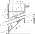
- Figs. 1 and 2 illustrate an example of such a thermally shielded probe. More particularly, Figs. 1 and 2 illustrate a probe 22 projecting through the exhaust duct and the LP turbine housing 24 to a location where a tip of the probe 22 is positioned adjacent to the LP turbine shaft for measuring an operating parameter (e.g. speed and/or torque) of the LP turbine 14a.
- an operating parameter e.g. speed and/or torque
- the exemplary probe 22 extends through a probe boss 32 mounted in a receiving hole defined at the top dead center of the exhaust duct 30 between the two diverging outlet conduit portions 30b, 30c thereof.
- the term "boss" is herein intended to generally refer to a mounting feature on a work piece. For instance, it can take the form of a protruding feature used to locate one component (e.g. a probe) within a pocket or hole of another component (e.g. the exhaust duct).
- the probe boss 32 may be provided in the form of a casting including a sleeve 32a and an outer flange 32b welded or otherwise suitably secured to the exhaust duct 30.
- the sleeve 32a has a slanted tubular portion that projects inwardly into the exhaust duct 30 in a "dead" air cavity 34 ( Fig. 2 ) radially between the LP turbine housing 24 the exhaust duct 30.
- the slanted tubular portion is aligned with an associated probe boss 36 provided on the turbine housing 24.
- the probes bosses 32, 36 provide a passage for the probe 22 through the exhaust case 15 and the turbine housing 24.
- the probe 22 extends through the registering probe bosses 32, 36 and into the LP turbine housing 24 next to the LP turbine shaft.
- the tip portion of the probe 22 is thermally shielded by the oil contained in the LP turbine housing 24.
- a probe heat shield is provided in the cavity 34 to protect the upper portion of the probe 22 from heat radiations emanating from the exhaust duct 30.
- the probe heat shield may be configured to create a heat shielding volume of air or air gap around the turbine probe 22 along a full radial extent of the cavity 34 between the exhaust duct 30 and the LP turbine housing 24 while allowing for the assembly of the exhaust duct 30 over the LP turbine housing 24 as shown in Fig. 5 .
- the protective enclosure formed by the thermal blanket 40a on the LP turbine housing 24 only radially extends along a portion of the cavity 34. Indeed, the radially outer end of the thermal blanket 40a through which the probe 22 extends is spaced radially inwardly from the inner end of the probe boss 32 (also herein referred to as the second probe boss) on the exhaust duct 30 so as to permit axial assembly of the exhaust duct 30 over the LP turbine housing 24.
- the portion of the probe 22 projecting radially outwardly from the turbine housing thermal blanket 40a is thermally shielded by the second mating portion 42 of the heat shield, that is the portion of the heat shield projecting radially inwardly from the exhaust duct 30.
- first and second mating portions 40, 42 of the probe heat shield cooperate to surround the probe 22 radially across a full extent of the cavity 34.
- the first and second mating portions 40, 42 of the heat shield have a radial overlap to account for thermal growth differential between the LP turbine housing 24 and the exhaust duct 30. Accordingly, in operation, the first and second mating portions 40, 42 of the probe heat shield can move relative to one another as a result of different thermal expansions between the exhaust duct 30 and the LP turbine housing 24 and yet still ensure the integrity of the insulation compartment they jointly form around the probe 22 in the cavity 34.
- the radial overlap is selected so that no radial gap is created between the first and second mating portions 40, 42 of the probe heat shield during engine operations.
- the second mating portion 42 of the heat shield comprises a thermal blanket 44 having a construction similar to that of the thermal blanket 40a used on the LP turbine housing 24 but structurally backed or reinforced by a support bracket 46 mounted to a radially inner surface 30a of the exhaust duct 30.
- the support bracket 46 can be made of sheet metal and is suitably attached to the exhaust duct 30, such as by welding, brazing or riveting.
- the thermal blanket 44 can be detachably mounted inside the support bracket 46 by any suitable means. According to the illustrated embodiment, fasteners, such as bolts 48 ( Fig. 4 ), are used to detachably attach the thermal blanket 44 to its support bracket 46.
Landscapes
- Engineering & Computer Science (AREA)
- Mechanical Engineering (AREA)
- General Engineering & Computer Science (AREA)
- Chemical & Material Sciences (AREA)
- Combustion & Propulsion (AREA)
- Supercharger (AREA)
- Exhaust Silencers (AREA)
Description
- The application relates generally to gas turbine engines and, more particularly, to a thermal protection for a probe disposed in an exhaust arrangement of a gas turbine engine.
- A gas turbine engine includes sections at low temperatures, namely cold section modules, and sections at high temperatures, namely hot section modules. The cold section modules include for example the compressor, while the hot section modules include for example, the combustor and the turbine. While some mechanical components may sustain the high temperatures prevailing in the hot section modules, probes may not sustain these high temperatures, and their functioning could be altered by the hot ambient gases present in hot section modules.
-
US 2015/198091 discloses an electric probe assembly, a gas turbine engine having the same and a method of cooling the same. - According to an aspect of the present invention, there is provided a gas turbine engine exhaust arrangement comprising: a probe, a turbine housing extending around a central axis and having a first probe boss; an exhaust case surrounding the turbine housing and having a second probe boss aligned with the first probe boss, the probe extending through the first and second probe bosses, a cavity radially between the turbine housing and the exhaust case; and a probe heat shield having first and second mating portions axially slidably fitted one over the other along the central axis and around the probe in the cavity, the first mating portion provided on a radially outer surface of the turbine housing, the second mating portion projecting radially inwardly from the exhaust case into the cavity.
- According to another aspect of the present invention, there is provided a gas turbine engine in accordance with
claim 11. - Features of embodiments are recited in the dependent claims.
- Reference is now made to the accompanying figures in which:
-
Fig. 1 is a schematic longitudinal/axial cross-section view of a boosted reverse flow gas turbine engine having a thermally shielded turbine probe; -
Fig. 2 is an enlarged axial cross-section view illustrating a probe heat shield assembly formed around a turbine probe in an air cavity between an exhaust case and a power turbine housing of the engine shown inFig. 1 ; -
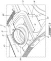
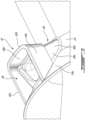
Fig. 3 is an enlarged isometric view of a portion of the exhaust case partly broken away to reveal a portion of the probe heat shield assembly including a U-shaped support
bracket mounted to a radially inner surface of the exhaust case and lined with a thermal blanket for
axial engagement over a mating heat shield portion on an outer surface of the power turbine housing; and -
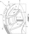
Fig. 4 is a front isometric view of the exhaust case illustrating the support bracket and the thermal blanket around exhaust probe boss; -
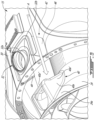
Fig. 5 is an isometric view illustrating a sequence of the assembly of the exhaust case over the power turbine housing, the U-shaped portion of the heat shield on the exhaust case aligned with the mating portion on the power turbine housing for axial engagement thereover; and -
Fig. 6 is a top isometric view illustrating the engagement of the exhaust case portion of the probe heat shield over the mating portion on the power turbine housing, the exhaust case being omitted for clarity. -
Fig. 1 illustrates agas turbine engine 10 of a type preferably provided for use in subsonic flight, generally comprising in serial flow communication anair inlet 11, acompressor 12 for pressurizing the air from theair inlet 11, acombustor 13 in which the compressed air is mixed with fuel and ignited for generating an annular stream of hot combustion gases, aturbine 14 for extracting energy from the combustion gases, and anexhaust case 15 through which the combustion gases exit theengine 10. Theturbine 14 includes a low pressure (LP) orpower turbine 14a drivingly connected to an input end of a fully enclosedreduction gearbox RGB 16. TheRGB 16 has an output end drivingly connected to anoutput shaft 18 configured to drive a rotatable load (not shown). The rotatable load can, for instance, take the form of a propeller or a rotor, such as a helicopter main rotor. Thegas turbine engine 10 has anengine centerline 17. According to the illustrated embodiment, the compressor and the turbine rotors are mounted in-line for rotation about theengine centerline 17. - The
gas turbine engine 10 has an axially extending central core which defines anannular gaspath 20 through which gases flow, as depicted by flow arrows inFig. 1 . The exemplary embodiment shown inFig. 1 is a "reverse-flow" engine because gases flow through thegaspath 20 from theair inlet 11 at a rear portion thereof, to theexhaust case 15 at a front portion thereof. According to one aspect, theengine 10 can have an engine architecture corresponding to that of the engine described in applicant'sUS Patent No. 10,393,027 issued on August 27, 2019 - As shown in
Fig. 1 , according to some embodiments, theexhaust case 15 comprises an asymmetric dualport exhaust duct 30 for exhausting combustion gases received from the last stage of theLP turbine 14a on opposed sides of theengine 10. The dualport exhaust duct 30 is qualified as "asymmetric" because the two exhaust ports thereof are not coaxial to the engine centerline 17 (i.e. the exhaust flow discharged from the exhaust duct is not axial, it is rather discharged in a direction that diverges from the engine centerline 17). According to at least some embodiments, the dualport exhaust duct 30 has a generally "Y-shaped" annular body including an annular central inlet conduit portion extending axially around theengine centerline 17 for receiving the annular flow of combustions gases discharged from the last stage ofLP turbine 14a, and first and second divergingoutlet conduit portions 30b, 30c branching off laterally from the central inlet conduit portion. According to some embodiments, the first and secondoutlet conduit portions 30b, 30c are identical. - Referring jointly to
Figs. 1 and5 , it can be seen that theturbine 14 comprises a power orLP turbine housing 24 mounted to and extending axially from theRGB 16 centrally into the hollow center of theannular exhaust duct 30. TheLP turbine housing 24 is configured to receive a bearing (not shown) for supporting the LP turbine rotor(s). As can be appreciated fromFig. 5 , during assembly, theexhaust duct 30 is axially slid in position over theLP turbine housing 24. Once theexhaust duct 30 has been properly positioned over theLP turbine housing 24, the two are detachably secured to the RGB such as by bolting at a front flange interface. - Referring back to
Fig. 1 , it can be seen that theengine 10 has a cold section C that is under a "relatively" cold ambient temperature. The cold section C includes theair inlet 11 and thecompressor 12. Theengine 10 also has a hot section H, which in use, is subject to high temperatures. The hot section H includes thecombustor 13, theturbine 14 and theexhaust case 15. For instance, the temperatures inside theturbine 14 are typically in excess of 1000 degree C. In use, the continuous flow of gas to which aturbine 14 is exposed can be at a temperature up to 1700 degree C. - The
engine 10 is equipped with a plurality of probes (sensors) for measuring various operating parameters, such as torque, speed, distance, temperature, pressure etc. Some of these probes are disposed in the hot section H of theengine 10. Accordingly, these probes need to be able to cope with the high temperatures prevailing in the hot section H of theengine 10. It may thus be necessary to thermally shield the probes in order to maintain the temperature of the probes within acceptable limits.Figs. 1 and2 illustrate an example of such a thermally shielded probe. More particularly,Figs. 1 and2 illustrate aprobe 22 projecting through the exhaust duct and theLP turbine housing 24 to a location where a tip of theprobe 22 is positioned adjacent to the LP turbine shaft for measuring an operating parameter (e.g. speed and/or torque) of theLP turbine 14a. - The
exemplary probe 22 extends through aprobe boss 32 mounted in a receiving hole defined at the top dead center of theexhaust duct 30 between the two divergingoutlet conduit portions 30b, 30c thereof. The term "boss" is herein intended to generally refer to a mounting feature on a work piece. For instance, it can take the form of a protruding feature used to locate one component (e.g. a probe) within a pocket or hole of another component (e.g. the exhaust duct). As exemplified inFigs. 2-4 , theprobe boss 32 may be provided in the form of a casting including asleeve 32a and anouter flange 32b welded or otherwise suitably secured to theexhaust duct 30. According to some embodiments, thesleeve 32a has a slanted tubular portion that projects inwardly into theexhaust duct 30 in a "dead" air cavity 34 (Fig. 2 ) radially between the LP turbine housing 24 theexhaust duct 30. The slanted tubular portion is aligned with an associatedprobe boss 36 provided on theturbine housing 24. The probes bosses 32, 36 provide a passage for theprobe 22 through theexhaust case 15 and the turbine housing 24. As shown inFig. 2 , theprobe 22 extends through the registeringprobe bosses probe 22 is thermally shielded by the oil contained in theLP turbine housing 24. However, the upper portion of theprobe 22 in thecavity 34 radially between theexhaust duct 30 and theturbine housing 24 does not benefit from the heat shielding action of the oil in theturbine housing 24. Accordingly, a probe heat shield is provided in thecavity 34 to protect the upper portion of theprobe 22 from heat radiations emanating from theexhaust duct 30. As will be seen herein after, the probe heat shield may be configured to create a heat shielding volume of air or air gap around theturbine probe 22 along a full radial extent of thecavity 34 between theexhaust duct 30 and theLP turbine housing 24 while allowing for the assembly of theexhaust duct 30 over theLP turbine housing 24 as shown inFig. 5 . - According to some embodiments, the probe heat shield includes a
first mating portion 40 pre-assembled on theturbine housing 24 and asecond mating portion 42 pre-assembled on theexhaust duct 30. As will be seen hereafter, the first andsecond mating portions probe 22. It will also be seen that the first andsecond mating portions cavity 40 between theexhaust duct 30 and the LP turbine housing 24. - As shown in
Figs. 2 ,5 and6 , thefirst mating portion 40 of the heat shield can include athermal blanket 40a mounted to a radially outer surface theLP turbine housing 24 around the LP turbine housing probe boss 36 (also herein referred to as the first probe boss). Thethermal blanket 40a can include a thermal insulation core (e.g. high temperature insulation fiber/wool materials) encapsulated in a metallic skin (e.g. sheet metal or metallic foil). As can be appreciated fromFigs. 2 and5 , thethermal blanket 40a on thepower turbine housing 24 can be mounted to theLP turbine housing 24 so as to form a protective enclosure around a first portion of the length theprobe 22 projecting radially outwardly from the LPturbine probe boss 36. However, as shown inFig. 2 , the protective enclosure formed by thethermal blanket 40a on theLP turbine housing 24 only radially extends along a portion of thecavity 34. Indeed, the radially outer end of thethermal blanket 40a through which theprobe 22 extends is spaced radially inwardly from the inner end of the probe boss 32 (also herein referred to as the second probe boss) on theexhaust duct 30 so as to permit axial assembly of theexhaust duct 30 over theLP turbine housing 24. The portion of theprobe 22 projecting radially outwardly from the turbine housingthermal blanket 40a is thermally shielded by thesecond mating portion 42 of the heat shield, that is the portion of the heat shield projecting radially inwardly from theexhaust duct 30. - As best shown in
Figs. 2-5 , thesecond mating portion 42 of the heat shield is configured to be axially engaged over thethermal blanket 40a on theturbine housing 24 and to extend radially outwardly therefrom to close the radial gap between the inner end of theprobe boss 32 and the radially outer end of thethermal blanket 40a on theturbine housing 24. The first andsecond mating portions probe 22 along all the radial height of thecavity 34 from theturbine housing 24 to theexhaust duct 30. In this way, the portion of the length of theprobe 22 extending through thecavity 34 can be fully capped with thermally insulating material while allowing for a blind assembly of the heatshield mating portions exhaust duct 30 and theturbine housing 24. That is the first andsecond mating portions probe 22 radially across a full extent of thecavity 34. As be appreciated fromFigs. 2 ,3 and6 , the first andsecond mating portions LP turbine housing 24 and theexhaust duct 30. Accordingly, in operation, the first andsecond mating portions exhaust duct 30 and theLP turbine housing 24 and yet still ensure the integrity of the insulation compartment they jointly form around theprobe 22 in thecavity 34. The radial overlap is selected so that no radial gap is created between the first andsecond mating portions - As best shown in
Figs. 3 and4 , thesecond mating portion 42 of the heat shield on theexhaust duct 30 has a generally U-shaped body including a pair ofside arms 42a extending axially from an axially facingbridge portion 42b to an axially open end facing themating portion 40 of the LP turbine housing 24 (the U-shaped body is opens towards theRGB 16 in the embodiment illustrated inFig 1 ). The radially inner end portion of theprobe boss 32 is received between theside arms 42a. It can be appreciated fromFigs. 2 and4 , that the U-shaped body extends radially inwardly beyond the inner end of the probe boss 32 (i.e. thesecond mating portion 42 of the heat shield projects deeper into thecavity 34 than the probe boss 32) for engagement over thefirst mating portion 40 of the heat shield. Theside arms 42a of thesecond mating portion 42 also project axially forward of the inner end of theprobe boss 32 and are configured for uniform axial abutment against thecorresponding slope surface 24a (Figs. 2 ,5 and6 ) on the RGB side of theLP turbine housing 24. The side-arms 42a are spaced so that the inner surface thereof fit in a sealing fashion over the correspondingsides 40a' (Figs. 5 and6 ) of thethermal blanket 40a on theLP turbine housing 24. The axial extent of theside arms 42a is selected so that thebridge portion 42b of the U-shape body abuts axially firmly against the corresponding axially facingsurface 40a" of the LP turbine housingthermal blanket 40a when the distal end surfaces of theside arms 42a axially abut against thefront slope surface 24a of theLP turbine housing 24. The U-shape body of thesecond mating portion 42 of the heat shield is sized and shaped to provide a tight fit engagement of thesecond mating portion 42 over thefirst mating portion 40 of the heat shield and, thus, provides a proper sealing interface between the first andsecond mating portions Fig. 5 , the heat shield is assembled by angularly aligning the first andsecond mating portions exhaust duct 30 over theLP turbine housing 24 as depicted by arrow A. The angular alignment of themating portions second mating portions LP turbine housing 24 andexhaust duct 30, respectively. Dead center visual indicators (not shown) can be provided on theexhaust duct 30 and theLP turbine housing 24 to further facilitate alignment. - According to some embodiments, the
second mating portion 42 of the heat shield comprises athermal blanket 44 having a construction similar to that of thethermal blanket 40a used on theLP turbine housing 24 but structurally backed or reinforced by asupport bracket 46 mounted to a radiallyinner surface 30a of theexhaust duct 30. Thesupport bracket 46 can be made of sheet metal and is suitably attached to theexhaust duct 30, such as by welding, brazing or riveting. Thethermal blanket 44 can be detachably mounted inside thesupport bracket 46 by any suitable means. According to the illustrated embodiment, fasteners, such as bolts 48 (Fig. 4 ), are used to detachably attach thethermal blanket 44 to itssupport bracket 46. Still according to the illustrated embodiment, both thesupport bracket 46 and thethermal blanket 44 have a U-shape configuration and cooperate to form the U-shaped body of thesecond mating portion 42 of the probe heat shield. Indeed, it can be appreciated fromFigs. 3 and4 that thesupport bracket 46 has a U-shape body with an inner surface lined with a corresponding U-shapedthermal blanket 44. As shown inFig. 4 , thethermal blanket 44 projects axially and radially beyond the outlines of theU-shape backing bracket 46 to provide a suitable interface with thethermal blanket 40a of thefirst mating portion 40 of the probe heat shield. It is thethermal blanket 44 that engages thethermal blanket 40a on theLP turbine housing 24. While the exemplifiedsupport bracket 46 shown in the drawings is near to being coextensive to thethermal blanket 44, it is understood that the size of the bracket could be reduced as long as it still provide sufficient backing surface for thethermal blanket 44 to retain its shape for proper engagement with themating portion 40 of the probe heat shield on theLP turbine housing 24. - It can be appreciated that at least some of the embodiments allow to create a heat shield around a
turbine probe 22 at assembly in a blind area for the assembler. According to one aspect, a protective volume of air is created around theprobe 22 by axial engagement of the heatshield mating portions turbine housing 24 and theexhaust duct 30. In this way, the protective volume of air can be automatically created by the assembly of theexhaust duct 30 over theturbine housing 24. The protective volume of air circumscribed by themating portions exhaust case 15. For instance, the volume of air around theprobe 22 can be in fluid communication with an air gap between the engine outer case and a surrounding nacelle (not shown). The volume of air around theprobe 22 can be fluidly connected to this external cooler volume of air via theprobe boss 32 on theexhaust case 15. - The above description is meant to be exemplary only, and one skilled in the art will recognize that changes may be made to the embodiments described without departing from the scope of the invention disclosed. For instance, while the probe installation has been described in the context of a turboprop/turboshaft engine architecture, it is understood that it could be applied to other engines, including turbofan and auxiliary power unit (APU) engines. Also, while the exemplified probe is installed on the power turbine housing, it is understood that it could be installed on other structures of the hot section of the gas turbine engine. Also, it is understood that the present disclosure is not limited to speed or torque probes. Other modifications which fall within the scope of the present invention as defined by the appended claims will be apparent to those skilled in the art, in light of a review of this disclosure.
Claims (11)
- A gas turbine engine exhaust arrangement comprising:a probe (22);a turbine housing (24) extending around a central axis (17) and having a first probe boss (36);an exhaust case (15) surrounding the turbine housing (24) and having a second probe boss (32) aligned with the first probe boss (36), the probe (22) extending through the first probe boss (36) and the second probe boss (32); anda cavity (34) radially between the turbine housing (24) and the exhaust case (15), characterised in that the gas turbine exhaust arrangement further comprises:
a probe heat shield having a first and a second mating portion (40, 42) axially slidably fitted one over the other along the central axis (17) and around the probe (22) in the cavity (34), the first mating portion (40) provided on a radially outer surface of the turbine housing (24), the second mating portion (42) projecting radially inwardly from the exhaust case (15) into the cavity (34). - The gas turbine engine exhaust arrangement according to claim 1, wherein the second mating portion (42) of the probe heat shield has a U-shaped body having a pair of axially extending arms (42a), the first mating portion (40) of the probe heat shield axially received between the axially extending arms (42a) of the U-shaped body.
- The gas turbine engine exhaust arrangement according to claim 2, wherein the second probe boss (32) projects radially inwardly from the exhaust case (15) into the cavity (34), and the U-shaped body surrounds the second probe boss (32) in the cavity (34).
- The gas turbine engine exhaust arrangement according to claim 2 or 3, wherein the U-shaped body projects radially inwardly into the cavity (34) to a location beyond an inner end of the second probe boss (32) to define a radial overlap with the first mating portion (40) of the probe heat shield on the turbine housing (24).
- The gas turbine engine exhaust arrangement according to any of claims 2 to 4, wherein the U-shaped body comprises a thermal blanket (44) structurally backed with a support bracket (46) mounted to a radially inner surface (30a) of the exhaust case (15).
- The gas turbine engine exhaust arrangement according to claim 5, wherein the thermal blanket (44) is removably mounted inside the support bracket (46).
- The gas turbine engine exhaust arrangement according to claim 5 or 6, wherein the support bracket (46) extends over a major portion of a surface area of the thermal blanket (44).
- The gas turbine engine exhaust arrangement according to any preceding claim, wherein the first and second mating portions (40, 42) of the heat shield define an air volume around the probe (22), the air volume in fluid communication with a source of air outside the exhaust case (15).
- The gas turbine engine exhaust arrangement according to any preceding claim, wherein the exhaust case (15) comprises an asymmetric dual exhaust duct (30) having first and second outlet portions (30b, 30c) diverging from the central axis (17) for discharging combustion gases, and wherein the second probe boss (32) is disposed between the first and second outlet portions (30b, 30c).
- The gas turbine engine exhaust arrangement according to claim 9, wherein the second probe boss (32) and the second mating portion (42) of the probe heat shield are located at a top dead center of the asymmetric dual exhaust duct (30).
- A gas turbine engine (10) comprising:a compressor (12) mounted for rotation about an axis (17);a turbine (14) drivingly connected to the compressor (12); anda gas turbine engine exhaust arrangement as defined in any preceding claim.
Applications Claiming Priority (1)
| Application Number | Priority Date | Filing Date | Title |
|---|---|---|---|
| US17/209,631 US11428122B1 (en) | 2021-03-23 | 2021-03-23 | Thermal protection for a gas turbine engine probe |
Publications (2)
| Publication Number | Publication Date |
|---|---|
| EP4063620A1 EP4063620A1 (en) | 2022-09-28 |
| EP4063620B1 true EP4063620B1 (en) | 2024-07-03 |
Family
ID=80930370
Family Applications (1)
| Application Number | Title | Priority Date | Filing Date |
|---|---|---|---|
| EP22163938.8A Active EP4063620B1 (en) | 2021-03-23 | 2022-03-23 | Thermal protection for a gas turbine engine probe |
Country Status (4)
| Country | Link |
|---|---|
| US (1) | US11428122B1 (en) |
| EP (1) | EP4063620B1 (en) |
| CA (1) | CA3152904A1 (en) |
| PL (1) | PL4063620T3 (en) |
Family Cites Families (17)
| Publication number | Priority date | Publication date | Assignee | Title |
|---|---|---|---|---|
| US4597675A (en) * | 1983-04-04 | 1986-07-01 | The Garrett Corporation | Mean temperature sensor |
| US5404760A (en) * | 1993-10-27 | 1995-04-11 | Westinghouse Electric Corporation | Blade path thermocouple and exhaust gas extraction probe for combustion turbines |
| US6037581A (en) * | 1996-01-15 | 2000-03-14 | Siemens Aktiengesellschaft | Device for recording a change in position at a turbine configuration |
| US7654093B2 (en) * | 2005-09-26 | 2010-02-02 | Pratt & Whitney Canada Corp. | Method of adjusting a triggering clearance and a trigger |
| US7913661B2 (en) | 2007-10-17 | 2011-03-29 | Honda Motor Co., Ltd. | Protective system for a crank angle sensor |
| US8997558B2 (en) * | 2011-03-29 | 2015-04-07 | General Electric Company | Combustor probe for gas turbine |
| US9631517B2 (en) * | 2012-12-29 | 2017-04-25 | United Technologies Corporation | Multi-piece fairing for monolithic turbine exhaust case |
| US9551281B2 (en) * | 2014-01-15 | 2017-01-24 | Pratt & Whitney Canada Corp. | Electric probe assembly, gas turbine engine having same and method of cooling same |
| US9605953B2 (en) * | 2014-10-30 | 2017-03-28 | Hamilton Sundstrand Corporation | Linkage assembly for sensor assembly and method of detecting angular position of a target through multiple structures |
| US9880059B2 (en) * | 2015-06-08 | 2018-01-30 | Siemens Energy, Inc. | Gas turbine exhaust diffuser mounted blade path thermocouple probe |
| US9897009B2 (en) | 2016-02-08 | 2018-02-20 | United Technologies Corporation | Flexible thermal blanket |
| US10883424B2 (en) | 2016-07-19 | 2021-01-05 | Pratt & Whitney Canada Corp. | Multi-spool gas turbine engine architecture |
| US10808624B2 (en) * | 2017-02-09 | 2020-10-20 | Pratt & Whitney Canada Corp. | Turbine rotor with low over-speed requirements |
| US11454128B2 (en) * | 2018-08-06 | 2022-09-27 | General Electric Company | Fairing assembly |
| US10794795B2 (en) * | 2018-09-14 | 2020-10-06 | Raytheon Technologies Corporation | Low profile embedded non-intrusive stress measurement system probe |
| US10816507B2 (en) * | 2019-03-20 | 2020-10-27 | Raytheon Technologies Corporation | Apparatus and method and system for inspecting a component of a gas turbine engine |
| US10876426B2 (en) * | 2019-04-09 | 2020-12-29 | Pratt & Whitney Canada Corp. | Removable turbine gaspath sensor |
-
2021
- 2021-03-23 US US17/209,631 patent/US11428122B1/en active Active
-
2022
- 2022-03-17 CA CA3152904A patent/CA3152904A1/en active Pending
- 2022-03-23 PL PL22163938.8T patent/PL4063620T3/en unknown
- 2022-03-23 EP EP22163938.8A patent/EP4063620B1/en active Active
Also Published As
| Publication number | Publication date |
|---|---|
| EP4063620A1 (en) | 2022-09-28 |
| US11428122B1 (en) | 2022-08-30 |
| PL4063620T3 (en) | 2024-11-18 |
| CA3152904A1 (en) | 2022-09-23 |
Similar Documents
| Publication | Publication Date | Title |
|---|---|---|
| EP4067625B1 (en) | Gas turbine engine including a probe | |
| US11781448B1 (en) | Shroud pin for gas turbine engine shroud | |
| EP3066318B1 (en) | Inner diffuser case for a gas turbine engine | |
| EP0578461A1 (en) | Turbine nozzle support arrangement | |
| EP2938857B1 (en) | Heat shield for cooling a strut | |
| EP2927595B1 (en) | Grommet assembly and method of design | |
| EP3640541B1 (en) | Slot cooled combustor | |
| EP2551458A2 (en) | Blade Cooling and Sealing System | |
| EP4299880A1 (en) | Probe heat shielding | |
| EP4047191B1 (en) | Instrumented turbine exhaust duct | |
| CA3145036A1 (en) | Torque probe cooling for gas turbine engine using external air | |
| EP2971683B1 (en) | Gas turbine engine heat exchanger manifold | |
| EP4063620B1 (en) | Thermal protection for a gas turbine engine probe | |
| US11506080B2 (en) | Gas turbine engine probe cooling | |
| EP3708782B1 (en) | Boas and methods of making a boas having fatigue resistant cooling inlets | |
| EP3971401B1 (en) | Aircraft propulsion system nozzle with internal flow passage | |
| US12044169B2 (en) | Sump arrangement for a gas turbine engine | |
| US11149692B2 (en) | Deflection mitigation structure for combustion system |
Legal Events
| Date | Code | Title | Description |
|---|---|---|---|
| PUAI | Public reference made under article 153(3) epc to a published international application that has entered the european phase |
Free format text: ORIGINAL CODE: 0009012 |
|
| STAA | Information on the status of an ep patent application or granted ep patent |
Free format text: STATUS: THE APPLICATION HAS BEEN PUBLISHED |
|
| AK | Designated contracting states |
Kind code of ref document: A1 Designated state(s): AL AT BE BG CH CY CZ DE DK EE ES FI FR GB GR HR HU IE IS IT LI LT LU LV MC MK MT NL NO PL PT RO RS SE SI SK SM TR |
|
| STAA | Information on the status of an ep patent application or granted ep patent |
Free format text: STATUS: REQUEST FOR EXAMINATION WAS MADE |
|
| 17P | Request for examination filed |
Effective date: 20230327 |
|
| RBV | Designated contracting states (corrected) |
Designated state(s): AL AT BE BG CH CY CZ DE DK EE ES FI FR GB GR HR HU IE IS IT LI LT LU LV MC MK MT NL NO PL PT RO RS SE SI SK SM TR |
|
| RIC1 | Information provided on ipc code assigned before grant |
Ipc: F01D 17/02 20060101AFI20231214BHEP |
|
| GRAP | Despatch of communication of intention to grant a patent |
Free format text: ORIGINAL CODE: EPIDOSNIGR1 |
|
| STAA | Information on the status of an ep patent application or granted ep patent |
Free format text: STATUS: GRANT OF PATENT IS INTENDED |
|
| INTG | Intention to grant announced |
Effective date: 20240125 |
|
| GRAS | Grant fee paid |
Free format text: ORIGINAL CODE: EPIDOSNIGR3 |
|
| GRAA | (expected) grant |
Free format text: ORIGINAL CODE: 0009210 |
|
| STAA | Information on the status of an ep patent application or granted ep patent |
Free format text: STATUS: THE PATENT HAS BEEN GRANTED |
|
| AK | Designated contracting states |
Kind code of ref document: B1 Designated state(s): AL AT BE BG CH CY CZ DE DK EE ES FI FR GB GR HR HU IE IS IT LI LT LU LV MC MK MT NL NO PL PT RO RS SE SI SK SM TR |
|
| REG | Reference to a national code |
Ref country code: CH Ref legal event code: EP |
|
| REG | Reference to a national code |
Ref country code: DE Ref legal event code: R096 Ref document number: 602022004223 Country of ref document: DE |
|
| REG | Reference to a national code |
Ref country code: LT Ref legal event code: MG9D |
|
| REG | Reference to a national code |
Ref country code: NL Ref legal event code: MP Effective date: 20240703 |
|
| PG25 | Lapsed in a contracting state [announced via postgrant information from national office to epo] |
Ref country code: PT Free format text: LAPSE BECAUSE OF FAILURE TO SUBMIT A TRANSLATION OF THE DESCRIPTION OR TO PAY THE FEE WITHIN THE PRESCRIBED TIME-LIMIT Effective date: 20241104 |
|
| REG | Reference to a national code |
Ref country code: AT Ref legal event code: MK05 Ref document number: 1700014 Country of ref document: AT Kind code of ref document: T Effective date: 20240703 |
|
| PG25 | Lapsed in a contracting state [announced via postgrant information from national office to epo] |
Ref country code: NL Free format text: LAPSE BECAUSE OF FAILURE TO SUBMIT A TRANSLATION OF THE DESCRIPTION OR TO PAY THE FEE WITHIN THE PRESCRIBED TIME-LIMIT Effective date: 20240703 |
|
| PG25 | Lapsed in a contracting state [announced via postgrant information from national office to epo] |
Ref country code: PT Free format text: LAPSE BECAUSE OF FAILURE TO SUBMIT A TRANSLATION OF THE DESCRIPTION OR TO PAY THE FEE WITHIN THE PRESCRIBED TIME-LIMIT Effective date: 20241104 Ref country code: NL Free format text: LAPSE BECAUSE OF FAILURE TO SUBMIT A TRANSLATION OF THE DESCRIPTION OR TO PAY THE FEE WITHIN THE PRESCRIBED TIME-LIMIT Effective date: 20240703 |
|
| PG25 | Lapsed in a contracting state [announced via postgrant information from national office to epo] |
Ref country code: NO Free format text: LAPSE BECAUSE OF FAILURE TO SUBMIT A TRANSLATION OF THE DESCRIPTION OR TO PAY THE FEE WITHIN THE PRESCRIBED TIME-LIMIT Effective date: 20241003 |
|
| PG25 | Lapsed in a contracting state [announced via postgrant information from national office to epo] |
Ref country code: FI Free format text: LAPSE BECAUSE OF FAILURE TO SUBMIT A TRANSLATION OF THE DESCRIPTION OR TO PAY THE FEE WITHIN THE PRESCRIBED TIME-LIMIT Effective date: 20240703 Ref country code: GR Free format text: LAPSE BECAUSE OF FAILURE TO SUBMIT A TRANSLATION OF THE DESCRIPTION OR TO PAY THE FEE WITHIN THE PRESCRIBED TIME-LIMIT Effective date: 20241004 |
|
| PG25 | Lapsed in a contracting state [announced via postgrant information from national office to epo] |
Ref country code: BG Free format text: LAPSE BECAUSE OF FAILURE TO SUBMIT A TRANSLATION OF THE DESCRIPTION OR TO PAY THE FEE WITHIN THE PRESCRIBED TIME-LIMIT Effective date: 20240703 |
|
| PG25 | Lapsed in a contracting state [announced via postgrant information from national office to epo] |
Ref country code: LV Free format text: LAPSE BECAUSE OF FAILURE TO SUBMIT A TRANSLATION OF THE DESCRIPTION OR TO PAY THE FEE WITHIN THE PRESCRIBED TIME-LIMIT Effective date: 20240703 |
|
| PG25 | Lapsed in a contracting state [announced via postgrant information from national office to epo] |
Ref country code: AT Free format text: LAPSE BECAUSE OF FAILURE TO SUBMIT A TRANSLATION OF THE DESCRIPTION OR TO PAY THE FEE WITHIN THE PRESCRIBED TIME-LIMIT Effective date: 20240703 Ref country code: IS Free format text: LAPSE BECAUSE OF FAILURE TO SUBMIT A TRANSLATION OF THE DESCRIPTION OR TO PAY THE FEE WITHIN THE PRESCRIBED TIME-LIMIT Effective date: 20241103 |
|
| PG25 | Lapsed in a contracting state [announced via postgrant information from national office to epo] |
Ref country code: HR Free format text: LAPSE BECAUSE OF FAILURE TO SUBMIT A TRANSLATION OF THE DESCRIPTION OR TO PAY THE FEE WITHIN THE PRESCRIBED TIME-LIMIT Effective date: 20240703 |
|
| PG25 | Lapsed in a contracting state [announced via postgrant information from national office to epo] |
Ref country code: RS Free format text: LAPSE BECAUSE OF FAILURE TO SUBMIT A TRANSLATION OF THE DESCRIPTION OR TO PAY THE FEE WITHIN THE PRESCRIBED TIME-LIMIT Effective date: 20241003 Ref country code: ES Free format text: LAPSE BECAUSE OF FAILURE TO SUBMIT A TRANSLATION OF THE DESCRIPTION OR TO PAY THE FEE WITHIN THE PRESCRIBED TIME-LIMIT Effective date: 20240703 |
|
| PG25 | Lapsed in a contracting state [announced via postgrant information from national office to epo] |
Ref country code: RS Free format text: LAPSE BECAUSE OF FAILURE TO SUBMIT A TRANSLATION OF THE DESCRIPTION OR TO PAY THE FEE WITHIN THE PRESCRIBED TIME-LIMIT Effective date: 20241003 Ref country code: NO Free format text: LAPSE BECAUSE OF FAILURE TO SUBMIT A TRANSLATION OF THE DESCRIPTION OR TO PAY THE FEE WITHIN THE PRESCRIBED TIME-LIMIT Effective date: 20241003 Ref country code: LV Free format text: LAPSE BECAUSE OF FAILURE TO SUBMIT A TRANSLATION OF THE DESCRIPTION OR TO PAY THE FEE WITHIN THE PRESCRIBED TIME-LIMIT Effective date: 20240703 Ref country code: IS Free format text: LAPSE BECAUSE OF FAILURE TO SUBMIT A TRANSLATION OF THE DESCRIPTION OR TO PAY THE FEE WITHIN THE PRESCRIBED TIME-LIMIT Effective date: 20241103 Ref country code: HR Free format text: LAPSE BECAUSE OF FAILURE TO SUBMIT A TRANSLATION OF THE DESCRIPTION OR TO PAY THE FEE WITHIN THE PRESCRIBED TIME-LIMIT Effective date: 20240703 Ref country code: GR Free format text: LAPSE BECAUSE OF FAILURE TO SUBMIT A TRANSLATION OF THE DESCRIPTION OR TO PAY THE FEE WITHIN THE PRESCRIBED TIME-LIMIT Effective date: 20241004 Ref country code: FI Free format text: LAPSE BECAUSE OF FAILURE TO SUBMIT A TRANSLATION OF THE DESCRIPTION OR TO PAY THE FEE WITHIN THE PRESCRIBED TIME-LIMIT Effective date: 20240703 Ref country code: ES Free format text: LAPSE BECAUSE OF FAILURE TO SUBMIT A TRANSLATION OF THE DESCRIPTION OR TO PAY THE FEE WITHIN THE PRESCRIBED TIME-LIMIT Effective date: 20240703 Ref country code: BG Free format text: LAPSE BECAUSE OF FAILURE TO SUBMIT A TRANSLATION OF THE DESCRIPTION OR TO PAY THE FEE WITHIN THE PRESCRIBED TIME-LIMIT Effective date: 20240703 Ref country code: AT Free format text: LAPSE BECAUSE OF FAILURE TO SUBMIT A TRANSLATION OF THE DESCRIPTION OR TO PAY THE FEE WITHIN THE PRESCRIBED TIME-LIMIT Effective date: 20240703 |
|
| REG | Reference to a national code |
Ref country code: DE Ref legal event code: R097 Ref document number: 602022004223 Country of ref document: DE |
|
| PG25 | Lapsed in a contracting state [announced via postgrant information from national office to epo] |
Ref country code: RO Free format text: LAPSE BECAUSE OF FAILURE TO SUBMIT A TRANSLATION OF THE DESCRIPTION OR TO PAY THE FEE WITHIN THE PRESCRIBED TIME-LIMIT Effective date: 20240703 Ref country code: SM Free format text: LAPSE BECAUSE OF FAILURE TO SUBMIT A TRANSLATION OF THE DESCRIPTION OR TO PAY THE FEE WITHIN THE PRESCRIBED TIME-LIMIT Effective date: 20240703 Ref country code: DK Free format text: LAPSE BECAUSE OF FAILURE TO SUBMIT A TRANSLATION OF THE DESCRIPTION OR TO PAY THE FEE WITHIN THE PRESCRIBED TIME-LIMIT Effective date: 20240703 |
|
| PG25 | Lapsed in a contracting state [announced via postgrant information from national office to epo] |
Ref country code: EE Free format text: LAPSE BECAUSE OF FAILURE TO SUBMIT A TRANSLATION OF THE DESCRIPTION OR TO PAY THE FEE WITHIN THE PRESCRIBED TIME-LIMIT Effective date: 20240703 |
|
| PG25 | Lapsed in a contracting state [announced via postgrant information from national office to epo] |
Ref country code: SK Free format text: LAPSE BECAUSE OF FAILURE TO SUBMIT A TRANSLATION OF THE DESCRIPTION OR TO PAY THE FEE WITHIN THE PRESCRIBED TIME-LIMIT Effective date: 20240703 Ref country code: IT Free format text: LAPSE BECAUSE OF FAILURE TO SUBMIT A TRANSLATION OF THE DESCRIPTION OR TO PAY THE FEE WITHIN THE PRESCRIBED TIME-LIMIT Effective date: 20240703 |
|
| PLBE | No opposition filed within time limit |
Free format text: ORIGINAL CODE: 0009261 |
|
| STAA | Information on the status of an ep patent application or granted ep patent |
Free format text: STATUS: NO OPPOSITION FILED WITHIN TIME LIMIT |
|
| 26N | No opposition filed |
Effective date: 20250404 |
|
| PG25 | Lapsed in a contracting state [announced via postgrant information from national office to epo] |
Ref country code: SE Free format text: LAPSE BECAUSE OF FAILURE TO SUBMIT A TRANSLATION OF THE DESCRIPTION OR TO PAY THE FEE WITHIN THE PRESCRIBED TIME-LIMIT Effective date: 20240703 |
|
| PG25 | Lapsed in a contracting state [announced via postgrant information from national office to epo] |
Ref country code: MC Free format text: LAPSE BECAUSE OF FAILURE TO SUBMIT A TRANSLATION OF THE DESCRIPTION OR TO PAY THE FEE WITHIN THE PRESCRIBED TIME-LIMIT Effective date: 20240703 |
|
| REG | Reference to a national code |
Ref country code: CH Ref legal event code: H13 Free format text: ST27 STATUS EVENT CODE: U-0-0-H10-H13 (AS PROVIDED BY THE NATIONAL OFFICE) Effective date: 20251024 |
|
| PG25 | Lapsed in a contracting state [announced via postgrant information from national office to epo] |
Ref country code: LU Free format text: LAPSE BECAUSE OF NON-PAYMENT OF DUE FEES Effective date: 20250323 |
|
| REG | Reference to a national code |
Ref country code: BE Ref legal event code: MM Effective date: 20250331 |
|
| PG25 | Lapsed in a contracting state [announced via postgrant information from national office to epo] |
Ref country code: BE Free format text: LAPSE BECAUSE OF NON-PAYMENT OF DUE FEES Effective date: 20250331 |
|
| PG25 | Lapsed in a contracting state [announced via postgrant information from national office to epo] |
Ref country code: CH Free format text: LAPSE BECAUSE OF NON-PAYMENT OF DUE FEES Effective date: 20250331 |
|
| PG25 | Lapsed in a contracting state [announced via postgrant information from national office to epo] |
Ref country code: IE Free format text: LAPSE BECAUSE OF NON-PAYMENT OF DUE FEES Effective date: 20250323 |
|
| PGFP | Annual fee paid to national office [announced via postgrant information from national office to epo] |
Ref country code: GB Payment date: 20260219 Year of fee payment: 5 |
|
| PGFP | Annual fee paid to national office [announced via postgrant information from national office to epo] |
Ref country code: DE Payment date: 20260219 Year of fee payment: 5 |
|
| PGFP | Annual fee paid to national office [announced via postgrant information from national office to epo] |
Ref country code: FR Payment date: 20260219 Year of fee payment: 5 |
|
| PGFP | Annual fee paid to national office [announced via postgrant information from national office to epo] |
Ref country code: CZ Payment date: 20260302 Year of fee payment: 5 |
|
| PGFP | Annual fee paid to national office [announced via postgrant information from national office to epo] |
Ref country code: PL Payment date: 20260302 Year of fee payment: 5 |