EP4063298A1 - Stacker crane - Google Patents
Stacker crane Download PDFInfo
- Publication number
- EP4063298A1 EP4063298A1 EP20890702.2A EP20890702A EP4063298A1 EP 4063298 A1 EP4063298 A1 EP 4063298A1 EP 20890702 A EP20890702 A EP 20890702A EP 4063298 A1 EP4063298 A1 EP 4063298A1
- Authority
- EP
- European Patent Office
- Prior art keywords
- column
- fixing
- inner member
- column member
- hole
- Prior art date
- Legal status (The legal status is an assumption and is not a legal conclusion. Google has not performed a legal analysis and makes no representation as to the accuracy of the status listed.)
- Pending
Links
Images




Classifications
-
- B—PERFORMING OPERATIONS; TRANSPORTING
- B65—CONVEYING; PACKING; STORING; HANDLING THIN OR FILAMENTARY MATERIAL
- B65G—TRANSPORT OR STORAGE DEVICES, e.g. CONVEYORS FOR LOADING OR TIPPING, SHOP CONVEYOR SYSTEMS OR PNEUMATIC TUBE CONVEYORS
- B65G1/00—Storing articles, individually or in orderly arrangement, in warehouses or magazines
- B65G1/02—Storage devices
- B65G1/04—Storage devices mechanical
-
- B—PERFORMING OPERATIONS; TRANSPORTING
- B66—HOISTING; LIFTING; HAULING
- B66F—HOISTING, LIFTING, HAULING OR PUSHING, NOT OTHERWISE PROVIDED FOR, e.g. DEVICES WHICH APPLY A LIFTING OR PUSHING FORCE DIRECTLY TO THE SURFACE OF A LOAD
- B66F9/00—Devices for lifting or lowering bulky or heavy goods for loading or unloading purposes
- B66F9/06—Devices for lifting or lowering bulky or heavy goods for loading or unloading purposes movable, with their loads, on wheels or the like, e.g. fork-lift trucks
- B66F9/075—Constructional features or details
- B66F9/08—Masts; Guides; Chains
-
- B—PERFORMING OPERATIONS; TRANSPORTING
- B65—CONVEYING; PACKING; STORING; HANDLING THIN OR FILAMENTARY MATERIAL
- B65G—TRANSPORT OR STORAGE DEVICES, e.g. CONVEYORS FOR LOADING OR TIPPING, SHOP CONVEYOR SYSTEMS OR PNEUMATIC TUBE CONVEYORS
- B65G1/00—Storing articles, individually or in orderly arrangement, in warehouses or magazines
- B65G1/02—Storage devices
- B65G1/04—Storage devices mechanical
- B65G1/0407—Storage devices mechanical using stacker cranes
-
- B—PERFORMING OPERATIONS; TRANSPORTING
- B66—HOISTING; LIFTING; HAULING
- B66F—HOISTING, LIFTING, HAULING OR PUSHING, NOT OTHERWISE PROVIDED FOR, e.g. DEVICES WHICH APPLY A LIFTING OR PUSHING FORCE DIRECTLY TO THE SURFACE OF A LOAD
- B66F9/00—Devices for lifting or lowering bulky or heavy goods for loading or unloading purposes
- B66F9/06—Devices for lifting or lowering bulky or heavy goods for loading or unloading purposes movable, with their loads, on wheels or the like, e.g. fork-lift trucks
- B66F9/07—Floor-to-roof stacking devices, e.g. "stacker cranes", "retrievers"
-
- B—PERFORMING OPERATIONS; TRANSPORTING
- B66—HOISTING; LIFTING; HAULING
- B66F—HOISTING, LIFTING, HAULING OR PUSHING, NOT OTHERWISE PROVIDED FOR, e.g. DEVICES WHICH APPLY A LIFTING OR PUSHING FORCE DIRECTLY TO THE SURFACE OF A LOAD
- B66F9/00—Devices for lifting or lowering bulky or heavy goods for loading or unloading purposes
- B66F9/06—Devices for lifting or lowering bulky or heavy goods for loading or unloading purposes movable, with their loads, on wheels or the like, e.g. fork-lift trucks
- B66F9/075—Constructional features or details
- B66F9/07504—Accessories, e.g. for towing, charging, locking
-
- B—PERFORMING OPERATIONS; TRANSPORTING
- B66—HOISTING; LIFTING; HAULING
- B66F—HOISTING, LIFTING, HAULING OR PUSHING, NOT OTHERWISE PROVIDED FOR, e.g. DEVICES WHICH APPLY A LIFTING OR PUSHING FORCE DIRECTLY TO THE SURFACE OF A LOAD
- B66F9/00—Devices for lifting or lowering bulky or heavy goods for loading or unloading purposes
- B66F9/06—Devices for lifting or lowering bulky or heavy goods for loading or unloading purposes movable, with their loads, on wheels or the like, e.g. fork-lift trucks
- B66F9/075—Constructional features or details
- B66F9/0755—Position control; Position detectors
-
- B—PERFORMING OPERATIONS; TRANSPORTING
- B66—HOISTING; LIFTING; HAULING
- B66F—HOISTING, LIFTING, HAULING OR PUSHING, NOT OTHERWISE PROVIDED FOR, e.g. DEVICES WHICH APPLY A LIFTING OR PUSHING FORCE DIRECTLY TO THE SURFACE OF A LOAD
- B66F9/00—Devices for lifting or lowering bulky or heavy goods for loading or unloading purposes
- B66F9/06—Devices for lifting or lowering bulky or heavy goods for loading or unloading purposes movable, with their loads, on wheels or the like, e.g. fork-lift trucks
- B66F9/075—Constructional features or details
- B66F9/12—Platforms; Forks; Other load supporting or gripping members
-
- H—ELECTRICITY
- H10—SEMICONDUCTOR DEVICES; ELECTRIC SOLID-STATE DEVICES NOT OTHERWISE PROVIDED FOR
- H10P—GENERIC PROCESSES OR APPARATUS FOR THE MANUFACTURE OR TREATMENT OF DEVICES COVERED BY CLASS H10
- H10P72/00—Handling or holding of wafers, substrates or devices during manufacture or treatment thereof
- H10P72/30—Handling or holding of wafers, substrates or devices during manufacture or treatment thereof for conveying, e.g. between different workstations
- H10P72/32—Handling or holding of wafers, substrates or devices during manufacture or treatment thereof for conveying, e.g. between different workstations between different workstations
- H10P72/3218—Conveying cassettes, containers or carriers
-
- H—ELECTRICITY
- H10—SEMICONDUCTOR DEVICES; ELECTRIC SOLID-STATE DEVICES NOT OTHERWISE PROVIDED FOR
- H10P—GENERIC PROCESSES OR APPARATUS FOR THE MANUFACTURE OR TREATMENT OF DEVICES COVERED BY CLASS H10
- H10P72/00—Handling or holding of wafers, substrates or devices during manufacture or treatment thereof
- H10P72/30—Handling or holding of wafers, substrates or devices during manufacture or treatment thereof for conveying, e.g. between different workstations
- H10P72/34—Handling or holding of wafers, substrates or devices during manufacture or treatment thereof for conveying, e.g. between different workstations the wafers being stored in a carrier, involving loading and unloading
- H10P72/3404—Storage means
Definitions
- An aspect of the present invention relates to stacker crane.
- Patent Literature 1 shows a stacker crane including a mast comprising a plurality of column members coupled with each other in a height direction and a elevating platform moving up and down along the mast.
- the plurality of column members are included in the mast. After a locational relation between the plurality of column members is adjusted and the column members are coupled, for example, at a factory, the coupled column members are decoupled and delivered to and recoupled at an installation site. The plurality of column members are recoupled so as to replicate the adjusted locational relation. However, time and effort for the replicate of the locational relation may be required.
- An aspect of the present invention provides a stacker crane capable of replicating easily an adjusted locational relation when the plurality of column members are coupled at an installation site.
- a stacker crane comprises a mast that includes a plurality of column members coupled with each other in a height direction and an elevating platform moving up and down along the mast.
- the stacker crane comprises a coupling structure to couple a first column member and a second column member adjacent to each other of the plurality of column members.
- the coupling structure includes an outer member attached over the first column member and the second column member, a first inner member arranged between the first column member and the outer member, a second inner member arranged between a second column member and the outer member, a first fixing member to fix the outer member with the first inner member to the first column member, a second fixing member to fix the outer member with the second inner member to the second column member, a third fixing member to fix the first inner member to the first column member, and a fourth fixing member to fix the second inner member to the second column member.
- the outer member and the first inner member are provided with a first positioning unit to specify a locational relation between the outer member and the first inner member
- the outer member and the second inner member are provided with a second positioning unit to specify a locational relation between the outer member and the second inner member.
- the first fixing member and the second fixing member are removed in order to release the coupled members, so that the outer member can be removed from the first inner member and the second inner member and at the same time the first inner member and the second inner member can remain fixed to the first column member and the second column member, respectively.
- the first fixing member and the second fixing member are reinstalled and the outer member is fixed to the first inner member and the second inner member, so that the first column member and the second column member can be recoupled.
- the first and the second positioning units specify the locational relations between the outer member and the first inner member and between the outer member and the second inner member, so that the first column member and the second column member are coupled in accordance with the locational relation adjusted at the factory. Therefore, when a plurality of the column members are coupled at an installation site, the adjusted locational relation can be easily replicated.
- the first positioning unit may include a first hole formed on one of the outer member and the first inner member and a first pin formed at one of the outer member and the first inner member and fitted into the first hole
- the second positioning unit may include a second hole formed on one of the outer member and the second inner member and a second pin formed at one of the outer member and the second inner member and fitted into the second hole.
- a plurality of the first holes and a plurality of the first pins are formed and a plurality of the second holes and a plurality of the second pins are formed.
- Any of the plurality of the first holes and any of the second holes may be long holes.
- the coupling structure may include a shim plate intervened at least any of between the first inner member and the first column member and between the second inner member and the second column member.
- the first inner member does not need to be removed and once being fixed to the second column member, the second inner member does not need to be removed, so that the shim plate intervened therebetween does not need to be removed once being fixed. Therefore, when the plurality of column members are coupled at an installation site, the shim plate does not need to be managed and the adjusted locational relation can be replicated more easily.
- the coupling structure may be provided on at least any of a side wall and a back wall of the first column member and the second column member. With this configuration, the first column member and the second column member can be coupled accurately.
- the coupling structure provided on the side wall of the first column member and the second column member further includes a front member coupled with the outer member and fixed to a front wall of the first column member and the second column member.
- An aspect of the present invention can provide a stacker crane capable of replicating easily an adjusted locational relation when a plurality of the column members are coupled at an installation site.
- Words 'up' and 'down' correspond to an upper direction and a lower direction of a vertical direction, respectively.
- a stocked 1 functions as a storage to store a container (transported article) 90 such as FOUP (Front Opening Unified Pod) storing articles such as semiconductor wafers or glass substrates.
- the stocker 1 is provided, for example, at a clean room.
- the stocker 1 includes mainly a stocker body 3, a rack 4, a stacker crane 7, and a controller 80.
- the stocker body 3 defines an inner space A of the stocker 1 and is formed with a plurality of partitions.
- the rack 4 stores the container 90 and are generally provided in one or two rows (two rows in the embodiment). Each of the rack 4 extends in X direction (width direction) and two adjacent racks 4, 4 are arranged in parallel or substantially parallel so as to face each other. Each of the rack 4 has a plurality of shelves 50 where the container 90 is placed and stored. The shelves 50 are arranged along X direction and Z direction (a vertical direction).
- the stacker crane 7 is a mechanism to load/unload the container 90 to/from each of the shelves 50 and to transfer between a loading port(not illustrated)and an unloading port (not illustrated) and each of the shelves 50 or between shelves 50.
- the stacker crane 7 is disposed in the area between two of the rack 4, 4 facing each other.
- the stacker crane 7 is capable of traveling on a rail (not illustrated) disposed in a floor along an extending direction (X direction) of the rack 4 to move along the rack 4 in X direction.
- the stacker crane 7 includes a travel unit 71, an elevator 74, a rotation unit 75, and a hand 79.
- the travel unit 71 is capable of traveling along a rail in X direction by a travel driver such as a motor.
- the elevator 74 includes a mast 100 and an elevating platform 73.
- the mast 100 is provided at the travel unit 71 and extends in Z direction.
- the elevating platform 73 is capable of moving up and down along the mast 100 by an elevation driver such as a motor.
- the rotation unit 75 rotates the hand 79 mounted on the rotation unit 75 around an axis along Z direction.
- the hand 79 places the container 90.
- the hand 79 is provided at the elevating platform 73.
- the hand 79 advance and retreat (advance outward from the elevating platform 73 and retreat on the elevating platform 73 in a plan view) to transfer the container 90 by use of a transfer device (not illustrated).
- Configurations, mechanisms, and locations of the travel unit 71, the elevator 74, the rotation unit 75, and the hand 79 are not specifically limited. Any known mechanisms or devices are adoptable for the travel unit 71, the elevator 74, the rotation unit 75, and the hand 79.
- the controller 80 controls components or parts of the stacker crane 7.
- the controller 80 is located, e.g. in the stocker body 3.
- the controller 80 includes CPU (Central Processing Unit), RAM (Random Access Memory) , and ROM ( Read Only Memory) .
- the controller 80 is capable of performing control operations in cooperation between hardware such as CPU, RAM, and ROM, and software such as program.
- the mast 100 of the stacker crane 7 will be now described as follows.
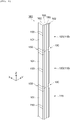
- the mast 100 is comprised of a plurality of column members 110 coupled in Z direction (a height direction).
- the column members 110 are elongate in Z direction and arranged adjacently in Z direction so as to face each other.
- the stacker crane 7 includes a plurality of coupling structures 150 to couple a pair of the column members 110 adjacent to each other in Z direction.
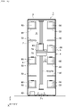
- each of the column members 110 includes a pair of side walls 101 extending in X direction seen from Z direction and facing each other in Y direction.
- Each of front walls 102 are provided at front side (one side of X direction) of each of the pair of side walls 101 so as to bend from each of the pair of side walls 101 to inner side in Y direction and connect with each of the pair of side walls 101.
- the pair of front wall 102 extend in Y direction seen from Z direction.
- a back wall 103 is provided backward from a center of the pair of side walls 101 in X direction between the pair of side walls 101.
- the back wall 103 extends in Y direction seen from Z direction.
- a rear side middle wall 104 is provided so as to divide a back side space defined by the side walls 101 and the back wall 103 at a center of the back wall 103 in Y direction.
- the rear middle wall 104 extends in X direction seen from Z direction.
- a cover 105 extending in Y direction is provided at an end of an inner side of each of the pair of front walls 102 in Y direction.
- a front space FA is defined by the side wall 101, the front wall 102, and the cover 105.
- a rail 106 for the elevating platform 73 ( FIG. 1 ) and a rail 107 for a balance weight (not illustrated) to balance with the evaluating platform 73 are arranged so as to extend in Z direction.
- the rail 106 is provided on a front surface 103a of the back wall 103.
- the rail 107 is provided on an inner surface 101a of any one of the side walls 101.
- an optional one of the plurality of column members 110 is referred to as an upper column member (first column member) 120 and another optional one of the plurality of column members 110, which is adjacent to a bottom side of the upper column member 120, is referred to as a lower column member (second column member) 130.
- Each of the coupling structures 150 is provided at each of an outer surfaces 101b of the pair of side walls 101 in the upper column member 120 and the lower column member 130. As shown in at least any of FIG. 3 to FIG. 8 , each of the coupling structures 150 has a double plate structure of outer side and inner side. Each of the coupling structures 150 includes an outer member 151, a first inner member 152, a second inner member 153, a first fixing member 154, a second fixing member 155, a third fixing member 156, and a forth fixing member 157.
- the outer member 151 is a rectangular member attached across the upper column member 120 and the lower column member 130.
- the outer member 151 is made of, e.g. an aluminum which is a metal generally having a high flatness.
- the outer member 151 abuts the first inner member 152 and the second inner member 153.
- the outer member 151 include first fixing holes 151a in which the first fixing members 154 are inserted, second fixing holes 151b in which the second fixing members 155 are inserted, through holes 151c to avoid an interference between the third members 156 fixing the first inner member 152 and the fourth fixing members 157 fixing the second inner member 153, a pair of first holes 151d into which a pair of first pins P1 (to be described later) of the first inner member 152 fit, a pair of second holes 151e into which a pair of second pins P2 (to be described later) of the second inner member 153 fit, and tapped holes 151f provided around the first holes 151d and the second holes 151e.
- the first fixing hole 151a is provided, e.g. in a grid shape on an upper part of the outer member 151.
- the second fixing hole 151b is provided, e.g. in a grid shape on a lower part of the outer member 151.
- the through hole 151c is a space to expose a head of the third fixing member 156 fixing the first inner member 152 and a head of the fourth fixing member 157 fixing the second inner member 153.
- the through hole 151c is formed between the first fixing holes 151a adjacent to each other in Z direction in the outer member 151 and between the second fixing holes 151b adjacent to each other in Z direction therein.
- the first hole 151d is formed in cross-sectional shape corresponding to the first pin P1 of the first inner member 152 at a position corresponding to the first pin P1.
- the first pin P1 is pressed into the first hole 151d, and tightened to fit into the first hole 151d.
- the first hole 151d is formed in each space among three of the through holes 151c located at the upper part of the outer member 151.
- One of a pair of the first holes 151d is a perfectly circular hole.
- the other of the pair of the first holes 151d is a long hole so that a direction in which the pair of the first holes 151d are lined up becomes a longitudinal direction.
- the second holes 151e is formed in cross-sectional shape corresponding to the second pin P2 of the second inner member 153 at a position corresponding to the second pin P2.
- the second hole 151e is a circular hole.
- the second pin P2 is pressed into the second hole 151e, and tightened to fit into the second hole 151e.
- the second hole 151e is formed in each space among three of the through holes 151c located at the lower part of the outer member 151.
- One of the pair of a second holes 151e is a perfectly circular hole.
- the other of the pair of a second holes 151e is a long hole so that a direction in which a pair of the second holes 151e are lined up becomes a longitudinal direction.
- the tapped hole 151f is provided around each of the first hole 151d and the second hole 151e.
- the tapped holes 151f is a screw hole used to pull out the first pins P1 from the first holes 151d and to pull out the second pins P2 from the second holes 151e.
- the coupling structure 150 provided at the side wall 101 further includes a front member 158.
- the front member 158 is a rectangular member attached over the upper column member 120 and the lower column member 130.
- the front member 158 abuts a front wall 102 of the upper column member 120 and the lower column member 130.
- the front member 158 is made of, e.g. aluminum.
- the front member 158 is coupled with the outer member 151 at an inner side of a front end of the outer member 151 with a screw 159 so as to be perpendicular to the outer member 151.
- the front member 158 is fixed to the front wall 102 with a bolt 162.
- the fixation (tightening) of the member 158 to the front wall 102 is enabled by use of a vertical groove MZ formed on the upper column member 120 and the lower column member 130.
- the first inner member 152 is a rectangular member arranged between the upper column member 120 and the outer member 151.
- the first inner member 152 is made of, e.g. a stainless steel which is a low-cost metal with a high stiffness.
- the first inner member 152 abuts the side wall 101 of a lower end of the upper column member 120.
- the first inner member 152 includes a first fixing hole 152a in which the first fixing member 154 is inserted, a third fixing hole 152b in which the third fixing member 156 is inserted, and a pair of the first pins P1 fitting into the first holes 151d of the outer member 151.
- the first fixing hole 152a is provided at a position capable of communicating with the first fixing hole 151a of the outer member 151 at an edge of the first inner member 152.
- the third fixing hole 152b is provided at a position capable of arranging within a through hole 151c of the outer member 151 on the first inner member 152.
- the third fixing hole 152b is provided between the first fixing holes 152a adjacent in Z direction on the first inner member 152.
- the first pin P1 is erected in a cross-sectional shape corresponding to the first hole 151d at a position corresponding to the first hole 151d of the outer member 151 on the first inner member 152.
- the first pin P1 is in a cylindrical shape.
- the first pin P1 is formed between the adjacent third fixing holes 152b on the first inner member 152.
- the first pin P1 is pressed into the first hole 151d, and tightened to fit into the first hole 151d.
- the first pin P1 protrudes longer than the thickness of the outer member 151.
- the first pin P1 is fixed to the first inner member 152, for example, by being welded.
- a method to fix the first pin P1 is not limited to the weld. The other methods can be used for the fixation of the first pin P1.
- the second inner member 153 is a rectangular member arranged between the lower column member 130 and the outer member 151.
- the second inner member 153 is made of, e.g. a stainless steel which is a low-cost metal with a high stiffness.
- the second inner member 153 abuts the side wall 101 of an upper end of the lower column member 130.
- the second inner member 153 includes a second fixing hole 153a in which the second fixing member 155 is inserted, a fourth fixing hole 153b in which the fourth fixing member 157 is inserted, and a pair of the second pins P2 fitting into the second holes 151e of the outer member 151.
- the second fixing hole 153a is provided at a position capable of communicating with the second fixing hole 151b of the outer member 151 at an edge of the second inner member 153.
- the fourth fixing hole 153b is provided at a position capable of arranging within a through hole 151c of the outer member 151 on the second inner member 153.
- the fourth fixing hole 153b is provided between the second fixing holes 153a adjacent in Z direction on the second inner member 153.
- the second pin P2 is erected in a cross-sectional shape corresponding to the second hole 151e at a position corresponding to the second hole 151e of the outer member 151 on the first inner member 152.
- the second pin P2 is formed in a cylindrical shape.
- the second pin P2 is formed between the adjacent fourth fixing holes 153b on the second inner member 153.
- the second pin P2 is pressed into the second hole 151e, and tightened to fit into the second hole 151e.
- the second pin P2 protrudes longer than the thickness of the outer member 151.
- the second pin P2 is fixed to the second inner member 153, for example, by being welded.
- a method to fix the second pin P2 is not limited to the weld. The other methods can be used for the fixation of the second pin P2.
- the first fixing member 154 fixes the outer member 151 along with the first inner member 152 to the upper column member 120.
- a co-fastening bolt is used as the first fixing member 154.
- the first fixing members 154 are inserted into the first fixing holes 151a, 152a.
- the fixation (tightening) of the first fixing member 154 to the upper column member 120 is enabled to by use of the vertical groove MZ formed on the upper column member 120.
- the second fixing member 155 fixes the outer member 151 along with the second inner member 153 to the lower column members 130.
- a co-fastening bolt is used as the second fixing member 155.
- the second fixing member 155 is inserted into the second fixing hole 151b, 153a.
- the fixation (tightening) of the second fixing member 155 to the lower column member 130 is enable by use of the vertical groove MZ formed on the lower column member 130.
- the third fixing member 156 fixes the first inner member 152 to the upper column member 120.
- a special screw titanium requiring a dedicated tool is used for the fixation and release as the third fixing member 156.
- the third fixing member 156 is inserted into the third fixing hole 152b.
- the fixation (tightening) of the third fixing member 156 to the upper column member 120 is enabled by use of the vertical groove MZ formed on the upper column member 120.
- the fourth fixing member 157 fixes the second inner member 153 to the lower column member 130.
- a special screw (tamperproof screw) requiring a dedicated tool is used for fixation and release as the fourth fixing member 157.
- the fourth fixing member 157 is inserted into the fourth fixing holes 153b.
- the fixation (tightening) of the fourth fixing member 157 to the lower column member 130 is enabled by use of the vertical groove MZ formed on the lower column member 130.
- the heads of the third fixing member 156 and the fourth fixing member 157 expose within the through hole 151c of the outer member 151.
- the first pin P1 of the first inner member 152 and the first hole 151d of the outer member 151 includes a first positioning unit to specify a locational relation between the outer member 151 and the first inner member 152.
- the second pin P2 of the second inner member 153 and the second hole 151e of the outer member 151 includes a second positioning unit to specify a locational relation between the outer member 151 and the second inner member 153.
- the stacker crane 7 further includes an intermediate wall coupling plate 160 as a coupler to couple between the upper column member 120 and the lower column member 130.
- the intermediate wall coupling plate 160 is a rectangular member attached over the upper column member 120 and the lower column member 130.
- the intermediate wall coupling plate 160 abuts the rear intermediate wall 104 of each of the upper column member 120 and the lower column member 130.
- the intermediate wall coupling plate 160 is made of, e.g. an aluminum.
- the intermediate wall coupling plate 160 is fixed to the rear intermediate wall 104 of each of the upper column member 120 and the lower column member 130 with a bolt 163.
- the fixation (tightening) of the intermediate wall coupling plate 160 to the rear intermediate wall 104 is enabled by use of the vertical groove MZ formed on the rear intermediate wall 104.
- the coupling structure 150 includes a shim plate 170 intervened between the first inner member 152 and the upper column member 120 and between the second inner member 153 and the lower column member 130.
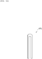
- the shim plate is a U-shaped plate seen from its width direction.
- the shim plate 170 is arranged such that one or more third fixing members 156 or one or more fourth fixing members 157 are located inside the U-shaped plate (such that the third fixing member 156 or the fourth fixing member is surrounded by the U-shaped plate) seen from its width direction.
- the shim plate 170 with an appropriate thickness is selected for use from a plurality of the sim plates with various thickness or the number of the shim plates to be used is selected.
- the shim plate 170 adjusts so that a surface of the first inner member 152 and a surface of the second inner member 153 can be located on a same and vertical plane.
- the coupling structure 150 is also provided at a back surface 103b of the back wall 103 of each of the upper column member 120 and the lower column member 130.
- the back surface 103b is divided into one side and the other side in Y direction by the rear immediate wall 104.
- the coupling structure 150 provided at the back wall 103 is provided at each of the one side and the other side.
- the coupling structure 150 provided at the back wall 103 is configured similarly to the coupling structure 150 provided at the side wall 101 except for a point that the front member 158 is not provided.
- the pair of the first pins P1 are fitted into and overlapped with the pair of the first holes 151d of the outer member 151.
- the pair of the second pin P2 of the second inner member 153 are fitted with and overlapped with the pair of the second holes 151e of the outer member 151. Therefore, a sub-assembly of the coupling structure 150 with the outer member 151, the first inner member 152, and the second inner member 153 assembled is obtained
- the outer member 151 and the first inner member 152 in the sub-assembly are tightened jointly and fixed to the upper column member 120 with the first fixing members 154.
- the outer member 151 and the second inner member 153 in the sub-assembly is tightened jointly and fixed to the lower column member 130 with the second fixing members 155.
- Only the first inner member 152 in the sub-assembly is fixed to the upper column member 120 with the third fixing members 156.
- Only the second inner member 153 in the sub-assembly is fixed to the lower column member 130 with the fourth fixing members 157. Therefore, the upper column member 120 and the lower column member 130 are coupled by the coupling structure 150.
- the shim plate 170 is intervened between the first inner member 152 and the upper column member 120 and the second inner member 153 and the lower column member 130 to adjust a locational relation between the upper column member 120 and the lower column member 130.
- the intermediate wall coupling plate 160 is fixed to the rear intermediate wall 104 of each of the upper column member 120 and the lower column member 130, so that the upper column member 120 and the lower column member 130 are coupled.
- the first fixing members 154 and the second fixing members 155 are removed.
- the outer member 151 is removed from the first inner member 152 and the second inner member 153 while the first inner member 152 and the second inner member 153 are fixed to the upper column member 120 and the lower column member 130.
- the intermediate wall coupling plate 160 is removed from the upper column member 120 and the lower column member 130.
- the upper column member 120 and the lower column member 130 are decoupled.
- the upper column member 120 and the lower column member 130 remaining decoupled are delivered and transferred to an installation site (also referred to as 'field' or 'installation field').
- the outer member 151 may remain fixed to the lower column member 130.
- the intermediate wall coupling plate 160 may remain fixed to the lower column member 130.
- the outer member 151 and the intermediate wall coupling plate 160 can function as a guide to abut the upper column member 120 and the lower column member 130 on each other when recoupling (to be described later).
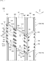
- the outer member 151 may be offset upward and temporarily fixed to the upper column member 120 as illustrated. Specifically, after the outer member 151 is removed from the first inner member 152 and the second inner body 153, the outer member 151 is moved upward to approximately a half of a vertical width thereof. The first fixing member 154 is inserted into the second fixing hole 151b and then the outer member 151 may be fixed to the upper column member 120 along with the first inner member 152, thus enabling to improve a handling ability of the coupling structure 150.
- the upper column member 120 and the lower column member 130 are recoupled. Specifically, the standing upper column member 120 is moved horizontally from a front side of the standing lower column member 130 close to each other and the upper column member 120 and the lower column member 130 are arranged to abut on each other in Z direction.
- the pair of first pins P1 of the first inner member 152 is fitted and overlapped with the pair of first holes 151d of the outer member 151 and the pair of second pins P2 of the second inner member 153 is fitted and overlapped with the pair of second holes 151e of the outer member 151.
- the outer member 151 and the first inner member 152 are tightened together and fixed to the upper column member 120 with the first fixing member 154, and the outer member 151 and the second inner member 153 are tightened together and fixed to the lower column member 130 with the second fixing member 155.
- the intermediate wall coupling plate 160 is fixed to the rear intermediate wall 104 of each of the upper column member 120 and the lower column member 130. As a result, the upper column member 120 and the lower column member 130 are recoupled and the installation of the mast 100 is completed.
- the coupling structure 150 For example, at a factory, in the stacker crane 7, after the locational relation is adjusted and the upper column member 120 and the lower column member 130 are coupled with each other by the coupling structure 150. In releasing this coupled members, the first fixing member 154 and the second fixing member 155 are removed, so that the outer member 151 can be removed from the first inner member 152 and the second inner member 153 and the first inner member 152 and the second inner member 153 can remain fixed to the upper column member 120 and the lower column member 130, respectively. At an installation site, the first fixing member 154 and the second fixing member 155 are reinstalled and the outer member 151 is fixed to the first inner member 152 and the second inner member 153, so that the upper column member 120 and the lower column member 130 can be recoupled.
- the first and the second positioning units (the first hole 151d, the second hole 151e, the first pin P1, and the second pin P2) specify the locational relations between the outer member 151 and the first inner member 152 and between the outer member 151 and the second inner member 153, so that the upper column member 120 and the lower column member 130 are coupled so as to replicate the locational relation adjusted at the factory. Therefore, the adjusted locational relation can be replicated without any special processing. When a plurality of the column members 110 are coupled at an installation site, the adjusted locational relation can be easily replicated, which enables to improve the quality and to reduce the working time.
- the first hole 151d and the first pin P1 are provided as the first positioning unit, and the second hole 151e and the second pin P2 are provided as the second positioning unit.
- the first pin P1 is fitted into the first hole 151d, so that the locational relation between the outer member 151 and the first inner member 152 can be specified.
- the second pin P2 is fitted into the second hole 151e, so that the locational relation between the outer member 151 and the second inner member 153 can be specified.
- a plurality of the first holes 151d and a plurality of the first pins P1 are formed and a plurality of the second holes 151e and a plurality of the second pins P2 are formed.
- Any of the plurality of the first holes 151d and any of the plurality of the second pins P2 are long holes.
- the coupling structure 150 has the shim plate 170 intervened between the first inner member 152 the upper column member 120 and between the second inner member 153 and the lower column member 130.
- the first inner member 152 does not need to be removed when being fixed once to the upper column member 120
- the second inner member 153 does not need to be removed when being fixed once to the lower column member 130, so that the shim plate 170 intervened therebetween does not need to be removed when being fixed once.
- the shim plate 170 does not need to be managed and the adjusted locational relation can be replicated more easily.
- the coupling structure 150 may be provided at the side wall 101 and the back wall 103 of the upper column member 120 and the lower column member 130.
- the upper column member 120 and the lower column member 130 can be coupled accurately.
- a surface requiring higher accurate coupling e.g. the inner surface 101a of the side wall 101 and the front surface 103a of the back wall 103 can be coupled with a sufficiently high accuracy.
- the coupling structure 150 provided at the side wall 101 of the upper column member 120 and the lower column member 130 further includes the front member 158 coupled with the outer member 151 and fixed by the front walls 102 of the upper column member 120 and the lower column member 130.
- any deformation of the mast 100 e.g. distortion such as expansion of space between the pair of front walls 102 can be prevented effectively.
- a rectangular reinforcement plate 190 (see FIG. 2 ) is abutted and fixed (tightened) at a position between the coupling structures 150 provided at an upper end and a lower end of outer surface of the side wall 101 of one column member 110.
- This kind of reinforcement plate 190 does not need to be provided in some cases.
- the coupling structure 150 may be applied to a stacker crane with a configuration different from the configurations of the above stacker crane 7.
- the container such as FOUP is described as an example of an article to be transported, however, a reticle pod to store a reticle may be used.
- a card board or a returnable box or the like may be used as an article to be transported.
- shape or material of each component of the coupling structure 150 is not especially limited and any shapes and materials may be used.
- the number of the column member 110 included in the mast 100 is not limited and may be two or more.
- the number of the coupling structure 150 is not limited and may be one or more.
- the first fixing member 154, the second fixing member 155, the third fixing member 156, and the fourth fixing member 157 are not limited.
- other general tightening tools may be used.
- one or more coupling structures 150 may be provided only at any of the side wall 101 and the back wall 103 of the upper column member 120 and the lower column member 130.
- the intermediate wall coupling plate 160 (see FIG. 3 ) does not need to be provided.
- the front member 158 (see FIG. 3 ) does not need to be provided.
- the shim plate 170 (see FIG. 10 ) may be provided at least one of between the first inner member 152 and the upper column member 120 and between the second inner member 153 and the lower column member 130. Alternatively, in the above preferred embodiment, the shim plate 170 does not need to be provided.
Landscapes
- Engineering & Computer Science (AREA)
- Transportation (AREA)
- Structural Engineering (AREA)
- Mechanical Engineering (AREA)
- Civil Engineering (AREA)
- Life Sciences & Earth Sciences (AREA)
- Geology (AREA)
- Warehouses Or Storage Devices (AREA)
- Radiation-Therapy Devices (AREA)
Abstract
Description
- An aspect of the present invention relates to stacker crane.
- For example, Patent Literature 1 shows a stacker crane including a mast comprising a plurality of column members coupled with each other in a height direction and a elevating platform moving up and down along the mast.
-
Japanese Patent No. 4826941 - In the stacker crane as described above, the plurality of column members are included in the mast. After a locational relation between the plurality of column members is adjusted and the column members are coupled, for example, at a factory, the coupled column members are decoupled and delivered to and recoupled at an installation site. The plurality of column members are recoupled so as to replicate the adjusted locational relation. However, time and effort for the replicate of the locational relation may be required.
- An aspect of the present invention provides a stacker crane capable of replicating easily an adjusted locational relation when the plurality of column members are coupled at an installation site.
- A stacker crane according to an aspect of the present invention comprises a mast that includes a plurality of column members coupled with each other in a height direction and an elevating platform moving up and down along the mast. The stacker crane comprises a coupling structure to couple a first column member and a second column member adjacent to each other of the plurality of column members. The coupling structure includes an outer member attached over the first column member and the second column member, a first inner member arranged between the first column member and the outer member, a second inner member arranged between a second column member and the outer member, a first fixing member to fix the outer member with the first inner member to the first column member, a second fixing member to fix the outer member with the second inner member to the second column member, a third fixing member to fix the first inner member to the first column member, and a fourth fixing member to fix the second inner member to the second column member. The outer member and the first inner member are provided with a first positioning unit to specify a locational relation between the outer member and the first inner member, and the outer member and the second inner member are provided with a second positioning unit to specify a locational relation between the outer member and the second inner member.
- For example, at a factory, in the
stacker crane 7, after a locational relation is adjusted and the first column member and the second column member are coupled with the coupling structure, the first fixing member and the second fixing member are removed in order to release the coupled members, so that the outer member can be removed from the first inner member and the second inner member and at the same time the first inner member and the second inner member can remain fixed to the first column member and the second column member, respectively. At an installation site, the first fixing member and the second fixing member are reinstalled and the outer member is fixed to the first inner member and the second inner member, so that the first column member and the second column member can be recoupled. The first and the second positioning units specify the locational relations between the outer member and the first inner member and between the outer member and the second inner member, so that the first column member and the second column member are coupled in accordance with the locational relation adjusted at the factory. Therefore, when a plurality of the column members are coupled at an installation site, the adjusted locational relation can be easily replicated. - In the stacker crane according to an aspect of the present invention, the first positioning unit may include a first hole formed on one of the outer member and the first inner member and a first pin formed at one of the outer member and the first inner member and fitted into the first hole, and the second positioning unit may include a second hole formed on one of the outer member and the second inner member and a second pin formed at one of the outer member and the second inner member and fitted into the second hole. With this configuration, the first pin is fitted with the first hole, so that the locational relation between the outer member and the first inner member can be specified. The second pin is fitted with the second hole, so that the locational relation between the outer member and the second inner member can be specified.
- In the stacker crane according to an aspect of the present invention, a plurality of the first holes and a plurality of the first pins are formed and a plurality of the second holes and a plurality of the second pins are formed. Any of the plurality of the first holes and any of the second holes may be long holes. With this configuration, the first pin can be easily fitted with the first hole and the second pin can be easily fitted with the second hole.
- In the stacker crane according to an aspect of the present invention, the coupling structure may include a shim plate intervened at least any of between the first inner member and the first column member and between the second inner member and the second column member. Once being fixed to the first column member, the first inner member does not need to be removed and once being fixed to the second column member, the second inner member does not need to be removed, so that the shim plate intervened therebetween does not need to be removed once being fixed. Therefore, when the plurality of column members are coupled at an installation site, the shim plate does not need to be managed and the adjusted locational relation can be replicated more easily.
- In the stacker crane according to an aspect of the present invention, the coupling structure may be provided on at least any of a side wall and a back wall of the first column member and the second column member. With this configuration, the first column member and the second column member can be coupled accurately.
- In the stacker crane according to an aspect of the present invention, the coupling structure provided on the side wall of the first column member and the second column member further includes a front member coupled with the outer member and fixed to a front wall of the first column member and the second column member. With this configuration, any deformation of the mast can be prevented effectively.
- An aspect of the present invention can provide a stacker crane capable of replicating easily an adjusted locational relation when a plurality of the column members are coupled at an installation site.
-
-
FIG. 1 is a sectional view showing a stocker including a stacker crane according to an embodiment. -
FIG. 2 is a perspective view showing a mast. -
FIG. 3 is a flat sectional view showing a mast. -
FIG. 4 is a perspective view showing a coupleing structure. -
FIG. 5 is a view showing an outer member of the coupling member seen from a width direction. -
FIG. 6 is a view showing a front side member of the coupling structure seen from the width direction. -
FIG. 7(a) is a view of a first inner member of the coupling struction seen from a width direction.FIG. 7(b) is a view of a second inner member of the coupling structure seen from the width direction. -
FIG. 8 is an exploded perspective view showing the coupling structure. -
FIG. 9 is a view showing an intermediate wall coupling plate seen from the width direction. -
FIG. 10 is a view of a shim plate seen from the width direction. -
FIG. 11 is a perspective view for explaining an example of mast installation. - Hereinafter, with reference to the drawings, an embodiment will be now described. In the description of the drawings, the same elements will be denoted by the same reference signs, without redundant description. Words 'up' and 'down' correspond to an upper direction and a lower direction of a vertical direction, respectively.
- a stocker including the stacker crane according to an embodiment will be now described. As shown in
FIG. 1 , a stocked 1 functions as a storage to store a container (transported article) 90 such as FOUP (Front Opening Unified Pod) storing articles such as semiconductor wafers or glass substrates. The stocker 1 is provided, for example, at a clean room. The stocker 1 includes mainly astocker body 3, arack 4, astacker crane 7, and acontroller 80. - The
stocker body 3 defines an inner space A of the stocker 1 and is formed with a plurality of partitions. Therack 4 stores thecontainer 90 and are generally provided in one or two rows (two rows in the embodiment). Each of therack 4 extends in X direction (width direction) and twoadjacent racks rack 4 has a plurality ofshelves 50 where thecontainer 90 is placed and stored. Theshelves 50 are arranged along X direction and Z direction (a vertical direction). - The
stacker crane 7 is a mechanism to load/unload thecontainer 90 to/from each of theshelves 50 and to transfer between a loading port(not illustrated)and an unloading port (not illustrated) and each of theshelves 50 or betweenshelves 50. Thestacker crane 7 is disposed in the area between two of therack stacker crane 7 is capable of traveling on a rail (not illustrated) disposed in a floor along an extending direction (X direction) of therack 4 to move along therack 4 in X direction. - the
stacker crane 7 includes atravel unit 71, anelevator 74, arotation unit 75, and ahand 79. Thetravel unit 71 is capable of traveling along a rail in X direction by a travel driver such as a motor. Theelevator 74 includes amast 100 and an elevatingplatform 73. Themast 100 is provided at thetravel unit 71 and extends in Z direction. The elevatingplatform 73 is capable of moving up and down along themast 100 by an elevation driver such as a motor. Therotation unit 75 rotates thehand 79 mounted on therotation unit 75 around an axis along Z direction. - The
hand 79 places thecontainer 90. Thehand 79 is provided at the elevatingplatform 73. Thehand 79 advance and retreat (advance outward from the elevatingplatform 73 and retreat on the elevatingplatform 73 in a plan view) to transfer thecontainer 90 by use of a transfer device (not illustrated). Configurations, mechanisms, and locations of thetravel unit 71, theelevator 74, therotation unit 75, and thehand 79 are not specifically limited. Any known mechanisms or devices are adoptable for thetravel unit 71, theelevator 74, therotation unit 75, and thehand 79. - The
controller 80 controls components or parts of thestacker crane 7. Thecontroller 80 is located, e.g. in thestocker body 3. Thecontroller 80 includes CPU (Central Processing Unit), RAM (Random Access Memory) , and ROM ( Read Only Memory) . Thecontroller 80 is capable of performing control operations in cooperation between hardware such as CPU, RAM, and ROM, and software such as program. - The
mast 100 of thestacker crane 7 will be now described as follows. - As shown in
FIG. 2 , themast 100 is comprised of a plurality ofcolumn members 110 coupled in Z direction (a height direction). Thecolumn members 110 are elongate in Z direction and arranged adjacently in Z direction so as to face each other. Thestacker crane 7 includes a plurality ofcoupling structures 150 to couple a pair of thecolumn members 110 adjacent to each other in Z direction. - As shown in
FIG, 3 , each of thecolumn members 110 includes a pair ofside walls 101 extending in X direction seen from Z direction and facing each other in Y direction. Each offront walls 102 are provided at front side (one side of X direction) of each of the pair ofside walls 101 so as to bend from each of the pair ofside walls 101 to inner side in Y direction and connect with each of the pair ofside walls 101. The pair offront wall 102 extend in Y direction seen from Z direction. Aback wall 103 is provided backward from a center of the pair ofside walls 101 in X direction between the pair ofside walls 101. Theback wall 103 extends in Y direction seen from Z direction. A rear sidemiddle wall 104 is provided so as to divide a back side space defined by theside walls 101 and theback wall 103 at a center of theback wall 103 in Y direction. The rearmiddle wall 104 extends in X direction seen from Z direction. - A
cover 105 extending in Y direction is provided at an end of an inner side of each of the pair offront walls 102 in Y direction. A front space FA is defined by theside wall 101, thefront wall 102, and thecover 105. Arail 106 for the elevating platform 73 (FIG. 1 ) and arail 107 for a balance weight (not illustrated) to balance with the evaluatingplatform 73 are arranged so as to extend in Z direction. Therail 106 is provided on a front surface 103a of theback wall 103. Therail 107 is provided on aninner surface 101a of any one of theside walls 101. Hereinafter, an optional one of the plurality ofcolumn members 110 is referred to as an upper column member (first column member) 120 and another optional one of the plurality ofcolumn members 110, which is adjacent to a bottom side of theupper column member 120, is referred to as a lower column member (second column member) 130. - Next, a structure to couple between the
upper column member 120 and thelower column member 130 with each other will be now described as follows. - Each of the
coupling structures 150 is provided at each of anouter surfaces 101b of the pair ofside walls 101 in theupper column member 120 and thelower column member 130. As shown in at least any ofFIG. 3 to FIG. 8 , each of thecoupling structures 150 has a double plate structure of outer side and inner side. Each of thecoupling structures 150 includes anouter member 151, a firstinner member 152, a secondinner member 153, a first fixingmember 154, asecond fixing member 155, athird fixing member 156, and a forth fixingmember 157. - As shown in
FIG. 3 ,FIG. 4 ,FIG. 5 , andFIG. 8 , theouter member 151 is a rectangular member attached across theupper column member 120 and thelower column member 130. Theouter member 151 is made of, e.g. an aluminum which is a metal generally having a high flatness. Theouter member 151 abuts the firstinner member 152 and the secondinner member 153. Theouter member 151 include first fixingholes 151a in which the first fixingmembers 154 are inserted, second fixing holes 151b in which thesecond fixing members 155 are inserted, throughholes 151c to avoid an interference between thethird members 156 fixing the firstinner member 152 and the fourth fixingmembers 157 fixing the secondinner member 153, a pair offirst holes 151d into which a pair of first pins P1 (to be described later) of the firstinner member 152 fit, a pair ofsecond holes 151e into which a pair of second pins P2 (to be described later) of the secondinner member 153 fit, and tappedholes 151f provided around thefirst holes 151d and thesecond holes 151e. - The
first fixing hole 151a is provided, e.g. in a grid shape on an upper part of theouter member 151. Thesecond fixing hole 151b is provided, e.g. in a grid shape on a lower part of theouter member 151. The throughhole 151c is a space to expose a head of the third fixingmember 156 fixing the firstinner member 152 and a head of the fourth fixingmember 157 fixing the secondinner member 153. The throughhole 151c is formed between the first fixingholes 151a adjacent to each other in Z direction in theouter member 151 and between the second fixing holes 151b adjacent to each other in Z direction therein. - The
first hole 151d is formed in cross-sectional shape corresponding to the first pin P1 of the firstinner member 152 at a position corresponding to the first pin P1. The first pin P1 is pressed into thefirst hole 151d, and tightened to fit into thefirst hole 151d. Thefirst hole 151d is formed in each space among three of the throughholes 151c located at the upper part of theouter member 151. One of a pair of thefirst holes 151d is a perfectly circular hole. The other of the pair of thefirst holes 151d is a long hole so that a direction in which the pair of thefirst holes 151d are lined up becomes a longitudinal direction. - The
second holes 151e is formed in cross-sectional shape corresponding to the second pin P2 of the secondinner member 153 at a position corresponding to the second pin P2. Thesecond hole 151e is a circular hole. The second pin P2 is pressed into thesecond hole 151e, and tightened to fit into thesecond hole 151e. Thesecond hole 151e is formed in each space among three of the throughholes 151c located at the lower part of theouter member 151. One of the pair of asecond holes 151e is a perfectly circular hole. The other of the pair of asecond holes 151e is a long hole so that a direction in which a pair of thesecond holes 151e are lined up becomes a longitudinal direction. - The tapped
hole 151f is provided around each of thefirst hole 151d and thesecond hole 151e. The tappedholes 151f is a screw hole used to pull out the first pins P1 from thefirst holes 151d and to pull out the second pins P2 from thesecond holes 151e. - As shown in
FIG. 3 ,FIG.4 ,FIG.6 , andFIG. 8 , thecoupling structure 150 provided at theside wall 101 further includes afront member 158. Thefront member 158 is a rectangular member attached over theupper column member 120 and thelower column member 130. Thefront member 158 abuts afront wall 102 of theupper column member 120 and thelower column member 130. Thefront member 158 is made of, e.g. aluminum. Thefront member 158 is coupled with theouter member 151 at an inner side of a front end of theouter member 151 with ascrew 159 so as to be perpendicular to theouter member 151. Thefront member 158 is fixed to thefront wall 102 with abolt 162. The fixation (tightening) of themember 158 to thefront wall 102 is enabled by use of a vertical groove MZ formed on theupper column member 120 and thelower column member 130. - As shown in
FIG. 3 ,FIG.4 ,FIG. 7(a) , andFIG. 8 , the firstinner member 152 is a rectangular member arranged between theupper column member 120 and theouter member 151. The firstinner member 152 is made of, e.g. a stainless steel which is a low-cost metal with a high stiffness. The firstinner member 152 abuts theside wall 101 of a lower end of theupper column member 120. The firstinner member 152 includes afirst fixing hole 152a in which the first fixingmember 154 is inserted, athird fixing hole 152b in which the third fixingmember 156 is inserted, and a pair of the first pins P1 fitting into thefirst holes 151d of theouter member 151. - The
first fixing hole 152a is provided at a position capable of communicating with thefirst fixing hole 151a of theouter member 151 at an edge of the firstinner member 152. Thethird fixing hole 152b is provided at a position capable of arranging within a throughhole 151c of theouter member 151 on the firstinner member 152. Thethird fixing hole 152b is provided between the first fixingholes 152a adjacent in Z direction on the firstinner member 152. - The first pin P1 is erected in a cross-sectional shape corresponding to the
first hole 151d at a position corresponding to thefirst hole 151d of theouter member 151 on the firstinner member 152. The first pin P1 is in a cylindrical shape. The first pin P1 is formed between the adjacent third fixingholes 152b on the firstinner member 152. The first pin P1 is pressed into thefirst hole 151d, and tightened to fit into thefirst hole 151d. The first pin P1 protrudes longer than the thickness of theouter member 151. The first pin P1 is fixed to the firstinner member 152, for example, by being welded. A method to fix the first pin P1 is not limited to the weld. The other methods can be used for the fixation of the first pin P1. - As shown in
FIG. 3 ,FIG.4 ,FIG. 7(b) , andFIG. 8 , the secondinner member 153 is a rectangular member arranged between thelower column member 130 and theouter member 151. The secondinner member 153 is made of, e.g. a stainless steel which is a low-cost metal with a high stiffness. The secondinner member 153 abuts theside wall 101 of an upper end of thelower column member 130. The secondinner member 153 includes asecond fixing hole 153a in which the second fixingmember 155 is inserted, afourth fixing hole 153b in which the fourth fixingmember 157 is inserted, and a pair of the second pins P2 fitting into thesecond holes 151e of theouter member 151. - The
second fixing hole 153a is provided at a position capable of communicating with thesecond fixing hole 151b of theouter member 151 at an edge of the secondinner member 153. Thefourth fixing hole 153b is provided at a position capable of arranging within a throughhole 151c of theouter member 151 on the secondinner member 153. Thefourth fixing hole 153b is provided between thesecond fixing holes 153a adjacent in Z direction on the secondinner member 153. - The second pin P2 is erected in a cross-sectional shape corresponding to the
second hole 151e at a position corresponding to thesecond hole 151e of theouter member 151 on the firstinner member 152. The second pin P2 is formed in a cylindrical shape. The second pin P2 is formed between the adjacent fourth fixingholes 153b on the secondinner member 153. The second pin P2 is pressed into thesecond hole 151e, and tightened to fit into thesecond hole 151e. The second pin P2 protrudes longer than the thickness of theouter member 151. The second pin P2 is fixed to the secondinner member 153, for example, by being welded. A method to fix the second pin P2 is not limited to the weld. The other methods can be used for the fixation of the second pin P2. - As shown in
FIG. 4 andFIG. 8 , the first fixingmember 154 fixes theouter member 151 along with the firstinner member 152 to theupper column member 120. For example, a co-fastening bolt is used as the first fixingmember 154. Thefirst fixing members 154 are inserted into the first fixingholes member 154 to theupper column member 120 is enabled to by use of the vertical groove MZ formed on theupper column member 120. - The
second fixing member 155 fixes theouter member 151 along with the secondinner member 153 to thelower column members 130. For example, a co-fastening bolt is used as the second fixingmember 155. Thesecond fixing member 155 is inserted into thesecond fixing hole member 155 to thelower column member 130 is enable by use of the vertical groove MZ formed on thelower column member 130. - The
third fixing member 156 fixes the firstinner member 152 to theupper column member 120. For example, a special screw (tamperproof screw) requiring a dedicated tool is used for the fixation and release as the third fixingmember 156. Thethird fixing member 156 is inserted into thethird fixing hole 152b. The fixation (tightening) of the third fixingmember 156 to theupper column member 120 is enabled by use of the vertical groove MZ formed on theupper column member 120. Thefourth fixing member 157 fixes the secondinner member 153 to thelower column member 130. For example, a special screw (tamperproof screw) requiring a dedicated tool is used for fixation and release as the fourth fixingmember 157. Thefourth fixing member 157 is inserted into the fourth fixingholes 153b. The fixation (tightening) of the fourth fixingmember 157 to thelower column member 130 is enabled by use of the vertical groove MZ formed on thelower column member 130. The heads of the third fixingmember 156 and the fourth fixingmember 157 expose within the throughhole 151c of theouter member 151. - In the above-described
coupling structure 150, the first pin P1 of the firstinner member 152 and thefirst hole 151d of theouter member 151 includes a first positioning unit to specify a locational relation between theouter member 151 and the firstinner member 152. The second pin P2 of the secondinner member 153 and thesecond hole 151e of theouter member 151 includes a second positioning unit to specify a locational relation between theouter member 151 and the secondinner member 153. - As shown in
FIG. 3 andFIG. 9 , thestacker crane 7 further includes an intermediatewall coupling plate 160 as a coupler to couple between theupper column member 120 and thelower column member 130. The intermediatewall coupling plate 160 is a rectangular member attached over theupper column member 120 and thelower column member 130. The intermediatewall coupling plate 160 abuts the rearintermediate wall 104 of each of theupper column member 120 and thelower column member 130. The intermediatewall coupling plate 160 is made of, e.g. an aluminum. The intermediatewall coupling plate 160 is fixed to the rearintermediate wall 104 of each of theupper column member 120 and thelower column member 130 with abolt 163. The fixation (tightening) of the intermediatewall coupling plate 160 to the rearintermediate wall 104 is enabled by use of the vertical groove MZ formed on the rearintermediate wall 104. - As shown in
FIG. 10 , thecoupling structure 150 includes ashim plate 170 intervened between the firstinner member 152 and theupper column member 120 and between the secondinner member 153 and thelower column member 130. The shim plate is a U-shaped plate seen from its width direction. Theshim plate 170 is arranged such that one or more third fixingmembers 156 or one or more fourth fixingmembers 157 are located inside the U-shaped plate (such that the third fixingmember 156 or the fourth fixing member is surrounded by the U-shaped plate) seen from its width direction. Theshim plate 170 with an appropriate thickness is selected for use from a plurality of the sim plates with various thickness or the number of the shim plates to be used is selected. Theshim plate 170 adjusts so that a surface of the firstinner member 152 and a surface of the secondinner member 153 can be located on a same and vertical plane. - Returning to
FIG. 3 , in thestacker crane 7, thecoupling structure 150 is also provided at a back surface 103b of theback wall 103 of each of theupper column member 120 and thelower column member 130. The back surface 103b is divided into one side and the other side in Y direction by the rearimmediate wall 104. Thecoupling structure 150 provided at theback wall 103 is provided at each of the one side and the other side. Thecoupling structure 150 provided at theback wall 103 is configured similarly to thecoupling structure 150 provided at theside wall 101 except for a point that thefront member 158 is not provided. - Hereinafter, an example of a case that the
mast 100 is installed at an installation site will be now described. - For example, at a production site such as a factory, the pair of the first pins P1 are fitted into and overlapped with the pair of the
first holes 151d of theouter member 151. At the same time, the pair of the second pin P2 of the secondinner member 153 are fitted with and overlapped with the pair of thesecond holes 151e of theouter member 151. Therefore, a sub-assembly of thecoupling structure 150 with theouter member 151, the firstinner member 152, and the secondinner member 153 assembled is obtained - The
outer member 151 and the firstinner member 152 in the sub-assembly are tightened jointly and fixed to theupper column member 120 with the first fixingmembers 154. Theouter member 151 and the secondinner member 153 in the sub-assembly is tightened jointly and fixed to thelower column member 130 with thesecond fixing members 155. Only the firstinner member 152 in the sub-assembly is fixed to theupper column member 120 with thethird fixing members 156. Only the secondinner member 153 in the sub-assembly is fixed to thelower column member 130 with the fourth fixingmembers 157. Therefore, theupper column member 120 and thelower column member 130 are coupled by thecoupling structure 150. - As needed, the
shim plate 170 is intervened between the firstinner member 152 and theupper column member 120 and the secondinner member 153 and thelower column member 130 to adjust a locational relation between theupper column member 120 and thelower column member 130. The intermediatewall coupling plate 160 is fixed to the rearintermediate wall 104 of each of theupper column member 120 and thelower column member 130, so that theupper column member 120 and thelower column member 130 are coupled. - Next, the first fixing
members 154 and thesecond fixing members 155 are removed. Using the tappedhole 151f of theouter member 151, theouter member 151 is removed from the firstinner member 152 and the secondinner member 153 while the firstinner member 152 and the secondinner member 153 are fixed to theupper column member 120 and thelower column member 130. The intermediatewall coupling plate 160 is removed from theupper column member 120 and thelower column member 130. As a result, theupper column member 120 and thelower column member 130 are decoupled. Theupper column member 120 and thelower column member 130 remaining decoupled are delivered and transferred to an installation site (also referred to as 'field' or 'installation field'). - At this step, for example, shown in
FIG. 11 , in thecoupling structure 150 provided at theback wall 103, theouter member 151 may remain fixed to thelower column member 130. In addition, the intermediatewall coupling plate 160 may remain fixed to thelower column member 130. As a result, theouter member 151 and the intermediatewall coupling plate 160 can function as a guide to abut theupper column member 120 and thelower column member 130 on each other when recoupling (to be described later). - In the
coupling structure 150 provided at theside wall 101, after being once removed, theouter member 151 may be offset upward and temporarily fixed to theupper column member 120 as illustrated. Specifically, after theouter member 151 is removed from the firstinner member 152 and the secondinner body 153, theouter member 151 is moved upward to approximately a half of a vertical width thereof. Thefirst fixing member 154 is inserted into thesecond fixing hole 151b and then theouter member 151 may be fixed to theupper column member 120 along with the firstinner member 152, thus enabling to improve a handling ability of thecoupling structure 150. - Then, at the installation site, the
upper column member 120 and thelower column member 130 are recoupled. Specifically, the standingupper column member 120 is moved horizontally from a front side of the standinglower column member 130 close to each other and theupper column member 120 and thelower column member 130 are arranged to abut on each other in Z direction. The pair of first pins P1 of the firstinner member 152 is fitted and overlapped with the pair offirst holes 151d of theouter member 151 and the pair of second pins P2 of the secondinner member 153 is fitted and overlapped with the pair ofsecond holes 151e of theouter member 151. Theouter member 151 and the firstinner member 152 are tightened together and fixed to theupper column member 120 with the first fixingmember 154, and theouter member 151 and the secondinner member 153 are tightened together and fixed to thelower column member 130 with the second fixingmember 155. The intermediatewall coupling plate 160 is fixed to the rearintermediate wall 104 of each of theupper column member 120 and thelower column member 130. As a result, theupper column member 120 and thelower column member 130 are recoupled and the installation of themast 100 is completed. - For example, at a factory, in the
stacker crane 7, after the locational relation is adjusted and theupper column member 120 and thelower column member 130 are coupled with each other by thecoupling structure 150. In releasing this coupled members, the first fixingmember 154 and the second fixingmember 155 are removed, so that theouter member 151 can be removed from the firstinner member 152 and the secondinner member 153 and the firstinner member 152 and the secondinner member 153 can remain fixed to theupper column member 120 and thelower column member 130, respectively. At an installation site, the first fixingmember 154 and the second fixingmember 155 are reinstalled and theouter member 151 is fixed to the firstinner member 152 and the secondinner member 153, so that theupper column member 120 and thelower column member 130 can be recoupled. The first and the second positioning units (thefirst hole 151d, thesecond hole 151e, the first pin P1, and the second pin P2) specify the locational relations between theouter member 151 and the firstinner member 152 and between theouter member 151 and the secondinner member 153, so that theupper column member 120 and thelower column member 130 are coupled so as to replicate the locational relation adjusted at the factory. Therefore, the adjusted locational relation can be replicated without any special processing. When a plurality of thecolumn members 110 are coupled at an installation site, the adjusted locational relation can be easily replicated, which enables to improve the quality and to reduce the working time. - In the
stacker crane 7, thefirst hole 151d and the first pin P1 are provided as the first positioning unit, and thesecond hole 151e and the second pin P2 are provided as the second positioning unit. The first pin P1 is fitted into thefirst hole 151d, so that the locational relation between theouter member 151 and the firstinner member 152 can be specified. The second pin P2 is fitted into thesecond hole 151e, so that the locational relation between theouter member 151 and the secondinner member 153 can be specified. - In the
stacker crane 7, a plurality of thefirst holes 151d and a plurality of the first pins P1 are formed and a plurality of thesecond holes 151e and a plurality of the second pins P2 are formed. Any of the plurality of thefirst holes 151d and any of the plurality of the second pins P2 are long holes. With this configuration, the first pin P1 can be easily fitted into thefirst hole 151d, and the second pin P2 can be easily fitted into thesecond hole 151e. - In the
stacker crane 7, thecoupling structure 150 has theshim plate 170 intervened between the firstinner member 152 theupper column member 120 and between the secondinner member 153 and thelower column member 130. The firstinner member 152 does not need to be removed when being fixed once to theupper column member 120, and similarly, the secondinner member 153 does not need to be removed when being fixed once to thelower column member 130, so that theshim plate 170 intervened therebetween does not need to be removed when being fixed once. Thus, when the plurality ofcolumn members 110 are coupled at an installation site, theshim plate 170 does not need to be managed and the adjusted locational relation can be replicated more easily. - In the
stacker crane 7, thecoupling structure 150 may be provided at theside wall 101 and theback wall 103 of theupper column member 120 and thelower column member 130. With this configuration, theupper column member 120 and thelower column member 130 can be coupled accurately. Especially, a surface requiring higher accurate coupling (e.g. theinner surface 101a of theside wall 101 and the front surface 103a of the back wall 103) can be coupled with a sufficiently high accuracy. - In the
stacker crane 7, thecoupling structure 150 provided at theside wall 101 of theupper column member 120 and thelower column member 130 further includes thefront member 158 coupled with theouter member 151 and fixed by thefront walls 102 of theupper column member 120 and thelower column member 130. With this configuration, any deformation of the mast 100 (e.g. distortion such as expansion of space between the pair of front walls 102) can be prevented effectively. - In the
stacker crane 7, in order to improve stiffness of the mast 100(in order to prevent deformation), a rectangular reinforcement plate 190 (seeFIG. 2 ) is abutted and fixed (tightened) at a position between thecoupling structures 150 provided at an upper end and a lower end of outer surface of theside wall 101 of onecolumn member 110. This kind ofreinforcement plate 190 does not need to be provided in some cases. - The preferred embodiment was described as above, however, an aspect of the present invention is not limited to the above preferred embodiment and various changes can be made without departing from the scope of the invention.
- For example, in the above embodiment, the
coupling structure 150 may be applied to a stacker crane with a configuration different from the configurations of theabove stacker crane 7. In the above embodiment, the container such as FOUP is described as an example of an article to be transported, however, a reticle pod to store a reticle may be used. A card board or a returnable box or the like may be used as an article to be transported. In the above embodiment, shape or material of each component of thecoupling structure 150 is not especially limited and any shapes and materials may be used. - In the above preferred embodiment, the number of the
column member 110 included in themast 100 is not limited and may be two or more. In the above preferred embodiment, the number of thecoupling structure 150 is not limited and may be one or more. In the above preferred embodiment, the first fixingmember 154, the second fixingmember 155, the third fixingmember 156, and the fourth fixingmember 157 are not limited. For example, other general tightening tools may be used. - In the above preferred embodiment, one or
more coupling structures 150 may be provided only at any of theside wall 101 and theback wall 103 of theupper column member 120 and thelower column member 130. In the above preferred embodiment, the intermediate wall coupling plate 160 (seeFIG. 3 ) does not need to be provided. In the above preferred embodiment, the front member 158 (seeFIG. 3 ) does not need to be provided. In the above preferred embodiment, the shim plate 170 (seeFIG. 10 ) may be provided at least one of between the firstinner member 152 and theupper column member 120 and between the secondinner member 153 and thelower column member 130. Alternatively, in the above preferred embodiment, theshim plate 170 does not need to be provided. -
- 7: Stacker crane
- 73: Elevating platform
- 100: Mast
- 101: Side wall
- 103: Back wall
- 110: Column member
- 120: Upper column member (column member, first column member)
- 130: Lower column member (column member, second column member)
- 150: Coupling structure
- 151: Outer member
- 151d: First hole (first positioning unit)
- 151e: Second hole (second positioning unit)
- 152: First inner member
- 153: Second inner member
- 154: First fixing member
- 155: Second fixing member
- 156: Third fixing member
- 157: Fourth fixing member
- 158: Front member
- 170: Shim plate
- P1: First pin (first positioning unit)
- P2: Second pin (second positioning unit)
Claims (6)
- A stacker crane comprising a mast that includes a plurality of column members coupled with each other in a height direction and an elevating platform moving up and down along the mast,the stacker crane, comprising a coupling structure to couple a first column member and a second column member adjacent to each other of the plurality of column members,wherein the coupling structure includes:an outer member attached over the first column member and the second column member;a first inner member arranged between the first column member and the outer member;a second inner member arranged between the second column member and the outer member;a first fixing member to fix the outer member to the first column member along with the first inner member;a second fixing member to fix the outer member to the second column member along with the second inner member;a third fixing member to fix the first inner member to the first column member; anda fourth fixing member to fix the second inner member to the second column member,the outer member and the first inner member are provided with a first positioning unit to specify a locational relation between the outer member and the first inner member, andthe outer member and the second inner member are provided with a second positioning unit to specify a locational relation between the outer member and the second inner member.
- The stacker crane according to claim 1,wherein the first positioning unit includes a first hole formed on one of the outer member and the first inner member and a first pin formed at one of the outer member and the first inner member and fitted into the first hole, andthe second positioning unit includes a second hole formed on one of the outer member and the second inner member and a second pin formed at one of the outer member and the second inner member and fitted into the second hole.
- the stacker crane according to claim 2,wherein a plurality of the first holes and a plurality of the first pins are formed,a plurality of the second holes and a plurality of the second pins are formed, andany of the plurality of the first holes and any of the plurality of the second holes are long holes.
- The stacker crane according to any of claims 1 to 3,
wherein the coupling structure includes a shim plate intervened at least any of between the first inner member and the first column member and between the second inner member and the second column member. - The stacker crane according to any of claims 1 to 4,
wherein the coupling structure is provided on at least any of a side wall and a back wall of the first column member and the second column member. - The stacker crane according to claim 5,
wherein the coupling structure provided on the side wall of the first column member and the second column member further includes a front member coupled with the outer member and fixed to a front wall of the first column member and the second column member.
Applications Claiming Priority (2)
| Application Number | Priority Date | Filing Date | Title |
|---|---|---|---|
| JP2019211508A JP2022188782A (en) | 2019-11-22 | 2019-11-22 | stacker crane |
| PCT/JP2020/036048 WO2021100313A1 (en) | 2019-11-22 | 2020-09-24 | Stacker crane |
Publications (2)
| Publication Number | Publication Date |
|---|---|
| EP4063298A1 true EP4063298A1 (en) | 2022-09-28 |
| EP4063298A4 EP4063298A4 (en) | 2023-12-13 |
Family
ID=75981184
Family Applications (1)
| Application Number | Title | Priority Date | Filing Date |
|---|---|---|---|
| EP20890702.2A Pending EP4063298A4 (en) | 2019-11-22 | 2020-09-24 | STACKING CRANE |
Country Status (7)
| Country | Link |
|---|---|
| US (1) | US12103836B2 (en) |
| EP (1) | EP4063298A4 (en) |
| JP (1) | JP2022188782A (en) |
| CN (1) | CN114630803B (en) |
| IL (1) | IL292862B2 (en) |
| TW (1) | TWI828949B (en) |
| WO (1) | WO2021100313A1 (en) |
Families Citing this family (4)
| Publication number | Priority date | Publication date | Assignee | Title |
|---|---|---|---|---|
| DE102020202438A1 (en) * | 2020-02-26 | 2021-08-26 | Mias Maschinenbau, Industrieanlagen & Service Gmbh | MAST ARRANGEMENT FOR A SHELVING UNIT |
| AT525824B1 (en) * | 2022-01-15 | 2024-01-15 | Vectron Logistics Gmbh | Mast for a stacker crane |
| JP7845239B2 (en) * | 2023-03-15 | 2026-04-14 | 株式会社ダイフク | Manufacturing method of mast structure |
| JP7845334B2 (en) * | 2023-11-02 | 2026-04-14 | 株式会社ダイフク | Stacker crane |
Family Cites Families (28)
| Publication number | Priority date | Publication date | Assignee | Title |
|---|---|---|---|---|
| JPS4826941B1 (en) | 1969-02-06 | 1973-08-17 | ||
| JP2555846B2 (en) * | 1992-09-24 | 1996-11-20 | 村田機械株式会社 | Automatic warehouse stacker crane |
| JPH06213216A (en) * | 1993-01-14 | 1994-08-02 | Daifuku Co Ltd | Taking-in/out device |
| JPH06247510A (en) * | 1993-02-25 | 1994-09-06 | Daifuku Co Ltd | Upper guide rail of take-in and-out device for automatic warehouse |
| JP2658834B2 (en) * | 1993-10-18 | 1997-09-30 | 村田機械株式会社 | mast |
| JPH07223707A (en) * | 1994-02-09 | 1995-08-22 | Murata Mach Ltd | Stacker crane of automated warehouse |
| JPH08225111A (en) * | 1995-02-23 | 1996-09-03 | Murata Mach Ltd | Stacker crane |
| JP3488550B2 (en) * | 1995-09-20 | 2004-01-19 | 東芝エレベータ株式会社 | Elevator guide rail connection device |
| JP3663696B2 (en) * | 1995-10-30 | 2005-06-22 | 株式会社豊田自動織機 | Mast connection structure |
| DE19704019A1 (en) | 1996-02-08 | 1997-12-18 | Frank Zurheide | Support element used for steel structure |
| JP3397147B2 (en) * | 1998-10-26 | 2003-04-14 | 株式会社豊田自動織機 | Stacker crane and mast for stacker crane |
| JP2002128210A (en) * | 2000-10-24 | 2002-05-09 | Nippon Yusoki Co Ltd | Stacker crane |
| JP3835377B2 (en) * | 2001-11-28 | 2006-10-18 | 村田機械株式会社 | Stacker crane |
| JP2005314077A (en) * | 2004-04-30 | 2005-11-10 | Ishikawajima Harima Heavy Ind Co Ltd | Stacker crane |
| DE102005007226B4 (en) | 2005-02-15 | 2007-03-29 | Siemens Ag | Connection of two rectangular pipe sections of a pipe, in particular a column of a stacker crane |
| JP4826941B2 (en) | 2005-08-22 | 2011-11-30 | ムラテックオートメーション株式会社 | Stacker crane |
| JP4754397B2 (en) | 2006-04-24 | 2011-08-24 | 新日本製鐵株式会社 | H-shaped steel joint structure and joining method |
| WO2012060146A1 (en) * | 2010-11-04 | 2012-05-10 | ムラテックオートメーション株式会社 | Stacker crane and method of loading and unloading goods |
| JP5459558B2 (en) * | 2010-12-24 | 2014-04-02 | 株式会社ダイフク | Stacker crane |
| JPWO2013161037A1 (en) * | 2012-04-26 | 2015-12-21 | 三菱電機株式会社 | Elevator apparatus and guide rail assembly method thereof |
| JP5686121B2 (en) * | 2012-07-26 | 2015-03-18 | 村田機械株式会社 | Stacker crane |
| US9802758B2 (en) * | 2013-02-20 | 2017-10-31 | Murata Machinery, Ltd. | Stacker crane and method for operating same |
| US9809433B2 (en) * | 2013-05-16 | 2017-11-07 | Murata Machinery, Ltd. | Stacker crane |
| TWI509167B (en) * | 2013-12-10 | 2015-11-21 | China Steel Corp | Energy dissipation joint assembly and the use of its seismic structure |
| JP6693356B2 (en) * | 2016-09-09 | 2020-05-13 | 株式会社ダイフク | Article carrier |
| CN106966331A (en) * | 2017-05-31 | 2017-07-21 | 邵旦彪 | A kind of double column stakcer cranes of laneway type |
| JP2019182630A (en) * | 2018-04-13 | 2019-10-24 | 村田機械株式会社 | Stacker crane |
| CN212799509U (en) * | 2020-08-07 | 2021-03-26 | 上海同锐工业自动化设备有限公司 | A fixing device for a stacker drive mechanism |
-
2019
- 2019-11-22 JP JP2019211508A patent/JP2022188782A/en active Pending
-
2020
- 2020-09-24 IL IL292862A patent/IL292862B2/en unknown
- 2020-09-24 EP EP20890702.2A patent/EP4063298A4/en active Pending
- 2020-09-24 US US17/776,621 patent/US12103836B2/en active Active
- 2020-09-24 CN CN202080076397.6A patent/CN114630803B/en active Active
- 2020-09-24 WO PCT/JP2020/036048 patent/WO2021100313A1/en not_active Ceased
- 2020-11-12 TW TW109139423A patent/TWI828949B/en active
Also Published As
| Publication number | Publication date |
|---|---|
| IL292862A (en) | 2022-07-01 |
| IL292862B2 (en) | 2026-03-01 |
| US12103836B2 (en) | 2024-10-01 |
| WO2021100313A1 (en) | 2021-05-27 |
| TWI828949B (en) | 2024-01-11 |
| TW202126570A (en) | 2021-07-16 |
| US20220402737A1 (en) | 2022-12-22 |
| JP2022188782A (en) | 2022-12-22 |
| EP4063298A4 (en) | 2023-12-13 |
| CN114630803A (en) | 2022-06-14 |
| CN114630803B (en) | 2023-05-16 |
| IL292862B1 (en) | 2025-11-01 |
Similar Documents
| Publication | Publication Date | Title |
|---|---|---|
| US12103836B2 (en) | Stacker crane | |
| EP3749595A1 (en) | Modular structure for an automated storage and retrieval system | |
| KR102414045B1 (en) | Storage rack | |
| US10522378B2 (en) | Storage rack | |
| KR20170082465A (en) | Article storage rack and article storage facility including same | |
| CN101293327A (en) | Pallet transfer system | |
| KR102146580B1 (en) | Module Structure for Piping Alignment and Method of Module Structure construction for Piping Alignment | |
| JP2009184687A (en) | Work transfer tray | |
| KR102326021B1 (en) | Apparatus for transferring doors | |
| CN212423809U (en) | Fixing device of electronic equipment | |
| KR200322749Y1 (en) | Pallet for loading plate materials | |
| CN101253100A (en) | Pillars for pallets | |
| US12159801B2 (en) | Storage device | |
| CN219258470U (en) | Chassis of bin robot and bin robot | |
| CN223878734U (en) | An adjustable positioning device | |
| WO2026105489A1 (en) | Stocker | |
| US20260077965A1 (en) | Storage device and storage unit | |
| US20050042065A1 (en) | Substrate transfer device with cassettes | |
| JP7243679B2 (en) | Goods storage shelf | |
| CN216002704U (en) | A transport device for door panels | |
| KR20200029799A (en) | Fabrication and Installation Method for Cell Guide Structures of Container Carrier | |
| JP4407587B2 (en) | Single wafer transfer tray | |
| KR100837725B1 (en) | Movable Support Device for Inventory Delivery System | |
| WO2018066208A1 (en) | Storage shelf | |
| KR100965526B1 (en) | Sheet conveying tray |
Legal Events
| Date | Code | Title | Description |
|---|---|---|---|
| STAA | Information on the status of an ep patent application or granted ep patent |
Free format text: STATUS: THE INTERNATIONAL PUBLICATION HAS BEEN MADE |
|
| PUAI | Public reference made under article 153(3) epc to a published international application that has entered the european phase |
Free format text: ORIGINAL CODE: 0009012 |
|
| STAA | Information on the status of an ep patent application or granted ep patent |
Free format text: STATUS: REQUEST FOR EXAMINATION WAS MADE |
|
| 17P | Request for examination filed |
Effective date: 20220621 |
|
| AK | Designated contracting states |
Kind code of ref document: A1 Designated state(s): AL AT BE BG CH CY CZ DE DK EE ES FI FR GB GR HR HU IE IS IT LI LT LU LV MC MK MT NL NO PL PT RO RS SE SI SK SM TR |
|
| DAV | Request for validation of the european patent (deleted) | ||
| DAX | Request for extension of the european patent (deleted) | ||
| A4 | Supplementary search report drawn up and despatched |
Effective date: 20231113 |
|
| RIC1 | Information provided on ipc code assigned before grant |
Ipc: H01L 21/677 20060101ALI20231107BHEP Ipc: B66F 9/07 20060101ALI20231107BHEP Ipc: B65G 1/04 20060101AFI20231107BHEP |
|
| REG | Reference to a national code |
Ref country code: DE Ref legal event code: R079 Free format text: PREVIOUS MAIN CLASS: B65G0001040000 Ipc: H10P0072300000 |
|
| GRAP | Despatch of communication of intention to grant a patent |
Free format text: ORIGINAL CODE: EPIDOSNIGR1 |
|
| STAA | Information on the status of an ep patent application or granted ep patent |
Free format text: STATUS: GRANT OF PATENT IS INTENDED |
|
| RIC1 | Information provided on ipc code assigned before grant |
Ipc: H10P 72/30 20260101AFI20260325BHEP Ipc: B66F 9/07 20060101ALI20260325BHEP Ipc: B65G 1/04 20060101ALI20260325BHEP |