EP4063168A1 - Relay diagnosis device, relay diagnosis method, battery system, and electric vehicle - Google Patents
Relay diagnosis device, relay diagnosis method, battery system, and electric vehicle Download PDFInfo
- Publication number
- EP4063168A1 EP4063168A1 EP21822358.4A EP21822358A EP4063168A1 EP 4063168 A1 EP4063168 A1 EP 4063168A1 EP 21822358 A EP21822358 A EP 21822358A EP 4063168 A1 EP4063168 A1 EP 4063168A1
- Authority
- EP
- European Patent Office
- Prior art keywords
- relay
- detection value
- diagnosis
- detector
- control unit
- Prior art date
- Legal status (The legal status is an assumption and is not a legal conclusion. Google has not performed a legal analysis and makes no representation as to the accuracy of the status listed.)
- Pending
Links
Images


Classifications
-
- B—PERFORMING OPERATIONS; TRANSPORTING
- B60—VEHICLES IN GENERAL
- B60L—PROPULSION OF ELECTRICALLY-PROPELLED VEHICLES; SUPPLYING ELECTRIC POWER FOR AUXILIARY EQUIPMENT OF ELECTRICALLY-PROPELLED VEHICLES; ELECTRODYNAMIC BRAKE SYSTEMS FOR VEHICLES IN GENERAL; MAGNETIC SUSPENSION OR LEVITATION FOR VEHICLES; MONITORING OPERATING VARIABLES OF ELECTRICALLY-PROPELLED VEHICLES; ELECTRIC SAFETY DEVICES FOR ELECTRICALLY-PROPELLED VEHICLES
- B60L3/00—Electric devices on electrically-propelled vehicles for safety purposes; Monitoring operating variables, e.g. speed, deceleration or energy consumption
- B60L3/04—Cutting off the power supply under fault conditions
-
- B—PERFORMING OPERATIONS; TRANSPORTING
- B60—VEHICLES IN GENERAL
- B60L—PROPULSION OF ELECTRICALLY-PROPELLED VEHICLES; SUPPLYING ELECTRIC POWER FOR AUXILIARY EQUIPMENT OF ELECTRICALLY-PROPELLED VEHICLES; ELECTRODYNAMIC BRAKE SYSTEMS FOR VEHICLES IN GENERAL; MAGNETIC SUSPENSION OR LEVITATION FOR VEHICLES; MONITORING OPERATING VARIABLES OF ELECTRICALLY-PROPELLED VEHICLES; ELECTRIC SAFETY DEVICES FOR ELECTRICALLY-PROPELLED VEHICLES
- B60L3/00—Electric devices on electrically-propelled vehicles for safety purposes; Monitoring operating variables, e.g. speed, deceleration or energy consumption
- B60L3/0023—Detecting, eliminating, remedying or compensating for drive train abnormalities, e.g. failures within the drive train
- B60L3/0061—Detecting, eliminating, remedying or compensating for drive train abnormalities, e.g. failures within the drive train relating to electrical machines
-
- G—PHYSICS
- G01—MEASURING; TESTING
- G01R—MEASURING ELECTRIC VARIABLES; MEASURING MAGNETIC VARIABLES
- G01R31/00—Arrangements for testing electric properties; Arrangements for locating electric faults; Arrangements for electrical testing characterised by what is being tested not provided for elsewhere
- G01R31/327—Testing of circuit interrupters, switches or circuit-breakers
-
- B—PERFORMING OPERATIONS; TRANSPORTING
- B60—VEHICLES IN GENERAL
- B60L—PROPULSION OF ELECTRICALLY-PROPELLED VEHICLES; SUPPLYING ELECTRIC POWER FOR AUXILIARY EQUIPMENT OF ELECTRICALLY-PROPELLED VEHICLES; ELECTRODYNAMIC BRAKE SYSTEMS FOR VEHICLES IN GENERAL; MAGNETIC SUSPENSION OR LEVITATION FOR VEHICLES; MONITORING OPERATING VARIABLES OF ELECTRICALLY-PROPELLED VEHICLES; ELECTRIC SAFETY DEVICES FOR ELECTRICALLY-PROPELLED VEHICLES
- B60L3/00—Electric devices on electrically-propelled vehicles for safety purposes; Monitoring operating variables, e.g. speed, deceleration or energy consumption
- B60L3/0023—Detecting, eliminating, remedying or compensating for drive train abnormalities, e.g. failures within the drive train
- B60L3/0046—Detecting, eliminating, remedying or compensating for drive train abnormalities, e.g. failures within the drive train relating to electric energy storage systems, e.g. batteries or capacitors
-
- B—PERFORMING OPERATIONS; TRANSPORTING
- B60—VEHICLES IN GENERAL
- B60L—PROPULSION OF ELECTRICALLY-PROPELLED VEHICLES; SUPPLYING ELECTRIC POWER FOR AUXILIARY EQUIPMENT OF ELECTRICALLY-PROPELLED VEHICLES; ELECTRODYNAMIC BRAKE SYSTEMS FOR VEHICLES IN GENERAL; MAGNETIC SUSPENSION OR LEVITATION FOR VEHICLES; MONITORING OPERATING VARIABLES OF ELECTRICALLY-PROPELLED VEHICLES; ELECTRIC SAFETY DEVICES FOR ELECTRICALLY-PROPELLED VEHICLES
- B60L58/00—Methods or circuit arrangements for monitoring or controlling batteries or fuel cells, specially adapted for electric vehicles
- B60L58/10—Methods or circuit arrangements for monitoring or controlling batteries or fuel cells, specially adapted for electric vehicles for monitoring or controlling batteries
- B60L58/18—Methods or circuit arrangements for monitoring or controlling batteries or fuel cells, specially adapted for electric vehicles for monitoring or controlling batteries of two or more battery modules
- B60L58/19—Switching between serial connection and parallel connection of battery modules
-
- B—PERFORMING OPERATIONS; TRANSPORTING
- B60—VEHICLES IN GENERAL
- B60L—PROPULSION OF ELECTRICALLY-PROPELLED VEHICLES; SUPPLYING ELECTRIC POWER FOR AUXILIARY EQUIPMENT OF ELECTRICALLY-PROPELLED VEHICLES; ELECTRODYNAMIC BRAKE SYSTEMS FOR VEHICLES IN GENERAL; MAGNETIC SUSPENSION OR LEVITATION FOR VEHICLES; MONITORING OPERATING VARIABLES OF ELECTRICALLY-PROPELLED VEHICLES; ELECTRIC SAFETY DEVICES FOR ELECTRICALLY-PROPELLED VEHICLES
- B60L58/00—Methods or circuit arrangements for monitoring or controlling batteries or fuel cells, specially adapted for electric vehicles
- B60L58/10—Methods or circuit arrangements for monitoring or controlling batteries or fuel cells, specially adapted for electric vehicles for monitoring or controlling batteries
- B60L58/18—Methods or circuit arrangements for monitoring or controlling batteries or fuel cells, specially adapted for electric vehicles for monitoring or controlling batteries of two or more battery modules
- B60L58/21—Methods or circuit arrangements for monitoring or controlling batteries or fuel cells, specially adapted for electric vehicles for monitoring or controlling batteries of two or more battery modules having the same nominal voltage
-
- G—PHYSICS
- G01—MEASURING; TESTING
- G01R—MEASURING ELECTRIC VARIABLES; MEASURING MAGNETIC VARIABLES
- G01R1/00—Details of instruments or arrangements of the types included in groups G01R5/00 - G01R13/00 and G01R31/00
- G01R1/20—Modifications of basic electric elements for use in electric measuring instruments; Structural combinations of such elements with such instruments
- G01R1/203—Resistors used for electric measuring, e.g. decade resistors standards, resistors for comparators, series resistors, shunts
-
- G—PHYSICS
- G01—MEASURING; TESTING
- G01R—MEASURING ELECTRIC VARIABLES; MEASURING MAGNETIC VARIABLES
- G01R1/00—Details of instruments or arrangements of the types included in groups G01R5/00 - G01R13/00 and G01R31/00
- G01R1/20—Modifications of basic electric elements for use in electric measuring instruments; Structural combinations of such elements with such instruments
- G01R1/206—Switches for connection of measuring instruments or electric motors to measuring loads
-
- G—PHYSICS
- G01—MEASURING; TESTING
- G01R—MEASURING ELECTRIC VARIABLES; MEASURING MAGNETIC VARIABLES
- G01R31/00—Arrangements for testing electric properties; Arrangements for locating electric faults; Arrangements for electrical testing characterised by what is being tested not provided for elsewhere
- G01R31/327—Testing of circuit interrupters, switches or circuit-breakers
- G01R31/3277—Testing of circuit interrupters, switches or circuit-breakers of low voltage devices, e.g. domestic or industrial devices, such as motor protections, relays, rotation switches
- G01R31/3278—Testing of circuit interrupters, switches or circuit-breakers of low voltage devices, e.g. domestic or industrial devices, such as motor protections, relays, rotation switches of relays, solenoids or reed switches
-
- G—PHYSICS
- G01—MEASURING; TESTING
- G01R—MEASURING ELECTRIC VARIABLES; MEASURING MAGNETIC VARIABLES
- G01R31/00—Arrangements for testing electric properties; Arrangements for locating electric faults; Arrangements for electrical testing characterised by what is being tested not provided for elsewhere
- G01R31/36—Arrangements for testing, measuring or monitoring the electrical condition of accumulators or electric batteries, e.g. capacity or state of charge [SoC]
- G01R31/382—Arrangements for monitoring battery or accumulator variables, e.g. SoC
- G01R31/3842—Arrangements for monitoring battery or accumulator variables, e.g. SoC combining voltage and current measurements
-
- B—PERFORMING OPERATIONS; TRANSPORTING
- B60—VEHICLES IN GENERAL
- B60L—PROPULSION OF ELECTRICALLY-PROPELLED VEHICLES; SUPPLYING ELECTRIC POWER FOR AUXILIARY EQUIPMENT OF ELECTRICALLY-PROPELLED VEHICLES; ELECTRODYNAMIC BRAKE SYSTEMS FOR VEHICLES IN GENERAL; MAGNETIC SUSPENSION OR LEVITATION FOR VEHICLES; MONITORING OPERATING VARIABLES OF ELECTRICALLY-PROPELLED VEHICLES; ELECTRIC SAFETY DEVICES FOR ELECTRICALLY-PROPELLED VEHICLES
- B60L2240/00—Control parameters of input or output; Target parameters
- B60L2240/40—Drive Train control parameters
- B60L2240/52—Drive Train control parameters related to converters
- B60L2240/529—Current
-
- B—PERFORMING OPERATIONS; TRANSPORTING
- B60—VEHICLES IN GENERAL
- B60L—PROPULSION OF ELECTRICALLY-PROPELLED VEHICLES; SUPPLYING ELECTRIC POWER FOR AUXILIARY EQUIPMENT OF ELECTRICALLY-PROPELLED VEHICLES; ELECTRODYNAMIC BRAKE SYSTEMS FOR VEHICLES IN GENERAL; MAGNETIC SUSPENSION OR LEVITATION FOR VEHICLES; MONITORING OPERATING VARIABLES OF ELECTRICALLY-PROPELLED VEHICLES; ELECTRIC SAFETY DEVICES FOR ELECTRICALLY-PROPELLED VEHICLES
- B60L2240/00—Control parameters of input or output; Target parameters
- B60L2240/40—Drive Train control parameters
- B60L2240/54—Drive Train control parameters related to batteries
- B60L2240/547—Voltage
-
- B—PERFORMING OPERATIONS; TRANSPORTING
- B60—VEHICLES IN GENERAL
- B60L—PROPULSION OF ELECTRICALLY-PROPELLED VEHICLES; SUPPLYING ELECTRIC POWER FOR AUXILIARY EQUIPMENT OF ELECTRICALLY-PROPELLED VEHICLES; ELECTRODYNAMIC BRAKE SYSTEMS FOR VEHICLES IN GENERAL; MAGNETIC SUSPENSION OR LEVITATION FOR VEHICLES; MONITORING OPERATING VARIABLES OF ELECTRICALLY-PROPELLED VEHICLES; ELECTRIC SAFETY DEVICES FOR ELECTRICALLY-PROPELLED VEHICLES
- B60L2240/00—Control parameters of input or output; Target parameters
- B60L2240/40—Drive Train control parameters
- B60L2240/54—Drive Train control parameters related to batteries
- B60L2240/549—Current
-
- B—PERFORMING OPERATIONS; TRANSPORTING
- B60—VEHICLES IN GENERAL
- B60Y—INDEXING SCHEME RELATING TO ASPECTS CROSS-CUTTING VEHICLE TECHNOLOGY
- B60Y2200/00—Type of vehicle
- B60Y2200/90—Vehicles comprising electric prime movers
- B60Y2200/91—Electric vehicles
-
- B—PERFORMING OPERATIONS; TRANSPORTING
- B60—VEHICLES IN GENERAL
- B60Y—INDEXING SCHEME RELATING TO ASPECTS CROSS-CUTTING VEHICLE TECHNOLOGY
- B60Y2306/00—Other features of vehicle sub-units
- B60Y2306/15—Failure diagnostics
-
- Y—GENERAL TAGGING OF NEW TECHNOLOGICAL DEVELOPMENTS; GENERAL TAGGING OF CROSS-SECTIONAL TECHNOLOGIES SPANNING OVER SEVERAL SECTIONS OF THE IPC; TECHNICAL SUBJECTS COVERED BY FORMER USPC CROSS-REFERENCE ART COLLECTIONS [XRACs] AND DIGESTS
- Y02—TECHNOLOGIES OR APPLICATIONS FOR MITIGATION OR ADAPTATION AGAINST CLIMATE CHANGE
- Y02T—CLIMATE CHANGE MITIGATION TECHNOLOGIES RELATED TO TRANSPORTATION
- Y02T10/00—Road transport of goods or passengers
- Y02T10/60—Other road transportation technologies with climate change mitigation effect
- Y02T10/70—Energy storage systems for electromobility, e.g. batteries
Definitions
- the present disclosure relates to fault diagnosis technology for a relay assembly provided in each of a plurality of battery packs connected in parallel.
- a battery system mounted in an electric vehicle may include a parallel pack assembly including a plurality of battery packs connected in parallel to meet the demand for high capacity such as long distance driving.
- a fault of the relay may be detected based on voltage at the load side contact of the relay provided in the battery pack.
- the load side contacts of a plurality of relays provided in each of the plurality of battery packs are connected in common to one another. Accordingly, it is possible to identify that at least one of the plurality of relays has a fault based on voltages at the load side contacts, but it is impossible to accurately identify which relay has the fault.
- the present disclosure is designed to solve the above-described problem, and therefore the present disclosure is directed to providing a relay diagnosis apparatus, a relay diagnosis method, a battery system and an electric vehicle for individually diagnosing a fault of a plurality of relays provided in a plurality of battery packs of a parallel pack assembly.
- a relay diagnosis apparatus is for a parallel pack assembly including a first battery pack having a first battery module and a first positive relay connected in series and a second battery pack having a second battery module and a second positive relay connected in series.
- the relay diagnosis apparatus includes a diagnosis unit including a diagnosis switch and a diagnosis resistor connected in series between a first pack terminal and a second pack terminal of the parallel pack assembly, a first detector configured to detect a first module current which is an electric current flowing the first battery module, a second detector configured to detect a second module current which is an electric current flowing through the second battery module, and a control unit operably coupled to the first positive relay, the second positive relay, the diagnosis switch, the first detector and the second detector.
- the control unit is configured to collect a first detection value from the first detector and a second detection value from the second detector in a first diagnosis period during which the first positive relay and the second positive relay are in an open operational state and the diagnosis switch is in a closed operational state.
- the control unit is configured to determine whether the first positive relay has a stuck-closed fault based on the first detection value and a first threshold.
- the control unit is configured to determine whether the second positive relay has the stuck-closed fault based on the second detection value and the first threshold.
- the control unit may be configured to determine that the first positive relay has the stuck-closed fault in response to the first detection value being larger than the first threshold.
- the control unit may be configured to determine that the second positive relay has the stuck-closed fault in response to the second detection value being larger than the first threshold.
- the relay diagnosis apparatus may further include a third detector configured to detect a first module voltage which is a voltage across the first battery module, and a fourth detector configured to detect a second module voltage which is a voltage across the second battery module.
- the control unit may be configured to collect a third detection value from the third detector and a fourth detection value from the fourth detector in the first diagnosis period.
- the control unit may be configured to collect a fifth detection value from the third detector and a sixth detection value from the fourth detector in a second diagnosis period during which the first positive relay and the second positive relay are in the open operational state and the diagnosis switch is in the open operational state.
- the control unit may be configured to determine whether the first positive relay has the stuck-closed fault based on the first detection value, the third detection value, the fifth detection value, the first threshold and the second threshold.
- the control unit may be configured to determine whether the second positive relay has the stuck-closed fault based on the second detection value, the fourth detection value, the sixth detection value, the first threshold and the second threshold.
- the control unit may be configured to determine that the first positive relay has the stuck-closed fault in response to the first detection value being larger than the first threshold and a difference between the third detection value and the fifth detection value is larger than the second threshold.
- the control unit may be configured to determine that the second positive relay has the stuck-closed fault in response to the second detection value being larger than the first threshold and a difference between the fourth detection value and the sixth detection value is larger than the second threshold.
- a battery system includes the relay diagnosis apparatus.
- An electric vehicle includes the battery system.
- a relay diagnosis method is provided to be executable by the relay diagnosis apparatus.
- the relay diagnosis method includes collecting, by the control unit, the first detection value from the first detector and the second detection value from the second detector in the first diagnosis period during which the first positive relay and the second positive relay are in the open operational state and the diagnosis switch is in the closed operational state, determining, by the control unit, whether the first positive relay has the stuck-closed fault based on the first detection value and the first threshold, and determining, by the control unit, whether the second positive relay has the stuck-closed fault based on the second detection value and the first threshold.
- control unit refers to a processing unit of at least one function or operation, and may be implemented by hardware or software alone or in combination.
- FIG. 1 is a diagram exemplarily showing a configuration of a power system according to the present disclosure
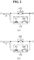
- FIG. 2 is a diagram exemplarily showing a configuration of a first detector and a second detector of FIG. 1
- FIG. 3 is a diagram exemplarily showing a configuration of a third detector and a fourth detector of FIG. 1 .
- the power system 1 may be, for example, an energy storage system and an electric vehicle.
- the power system 1 includes a battery system 10, an inverter 2 and an electrical load 3.
- the electrical load 3, may be, for example, an electric motor.
- the battery system 10 includes a parallel pack assembly 20 and a relay diagnosis apparatus 100.
- the battery system 10 may further include a main relay assembly MR.
- the parallel pack assembly 20 refers to a pack group including a parallel circuit of at least two battery packs, i.e., a first battery pack 21 and a second battery pack 22, connected in parallel.
- the main relay assembly MR may be connected between a pair of pack terminals P1, P2 provided in the parallel pack assembly 20 and a pair of power terminals provided in the inverter 2.
- the main relay assembly MR includes a first main relay MR1.
- the two contacts of the first main relay MR1 are connected to the first pack terminal P1 and one of the pair of power terminals, respectively.
- the main relay assembly MR may further include a second main relay MR2.
- the two contacts of the second main relay MR2 are connected to the second pack terminal P2 and the other of the pair of power terminals, respectively.
- the inverter 2 converts direct current (DC) power supplied from the parallel pack assembly 20 to alternating current (AC) power and supplies it to the electrical load 3.
- DC direct current
- AC alternating current
- the first battery pack 21 includes a first battery module 31 and a first relay assembly 41.
- the first battery module 31 includes a plurality of battery cells electrically connected in series and/or in parallel.
- the first relay assembly 41 is connected in series to the first battery module 31.
- the first relay assembly 41 includes a first positive relay 41A.
- the two contacts of the first positive relay 41A are connected to a positive electrode terminal of the first battery module 31 and the first pack terminal P1, respectively.
- the first relay assembly 41 may further include a first negative relay 41B.
- the two contacts of the first negative relay 41B are connected to a negative electrode terminal of the first battery module 31 and the second pack terminal P2, respectively.
- the second battery pack 22 includes a second battery module 32 and a second relay assembly 42.
- the second battery module 32 includes a plurality of battery cells electrically connected in series and/or in parallel.
- the second relay assembly 42 is connected in series to the second battery module 32.
- the second relay assembly 42 includes a second positive relay 42A.
- the two contacts of the second positive relay 42A are connected to a positive electrode terminal of the second battery module 32 and the first pack terminal P1, respectively.
- the second relay assembly 42 may further include a second negative relay 42B.
- the two contacts of the second negative relay 42B are connected to a negative electrode terminal of the second battery module 32 and the second pack terminal P2, respectively.
- Each battery cell of the first battery module 31 and the second battery module 32 is not limited to a particular type, and includes any type of battery that can be charged and discharged repeatedly, such as, for example, a lithium ion cell.
- the relay diagnosis apparatus 100 includes a first detector 110, a second detector 120, a diagnosis unit 150 and a control unit 160.
- the relay diagnosis apparatus 100 may further include at least one of a third detector 130, a fourth detector 140 or an interface unit 170.
- the diagnosis unit 150 is connected between the first pack terminal P1 and the second pack terminal P2.
- the diagnosis unit 150 includes a diagnosis switch SWD and a diagnosis resistor RD connected in series.
- the diagnosis switch SWD may include a well-known switching device such as, for example, a Field Effect Transistor (FET).
- FET Field Effect Transistor
- the first detector 110 is configured to detect a first module current I1 which is an electric current flowing through the first battery module 31.
- the first detector 110 may be installed on a negative electrode side line of the first battery module 31.
- the first detector 110 generates a detection signal S1 indicating the first module current I1.
- the second detector 120 is configured to detect a second module current I2 which is an electric current flowing through the second battery module 32.
- the second detector 120 may be installed on a negative electrode side line of the second battery module 32.
- the second detector 120 generates a detection signal S1 indicating the second module current 12.
- the first detector 110 may be connected in parallel to the first negative relay 41B.
- the first detector 110 may include a first resistor R1 and a first switch SW1.
- a series circuit of the first resistor R1 and the first switch SW1 may be connected in parallel to the first negative relay 41B.
- the first switch SW1 may be removed from the first detector 110.
- the first resistor R1 may be connected in series between the negative electrode terminal of the first battery module 31 and the second pack terminal P2.
- the second detector 120 may be connected in parallel to the second negative relay 42B.
- the second detector 120 may include a second resistor R2 and a second switch SW2.
- a series circuit of the second resistor R2 and the second switch SW2 may be connected in parallel to the second negative relay 42B.
- the second switch SW2 may be removed from the second detector 120.
- the second resistor R2 may be connected in series between the negative electrode terminal of the second battery module 32 and the second pack terminal P2.
- the third detector 130 is configured to detect a first module voltage V1 which is a voltage across the first battery module 31.
- the third detector 130 generates a detection signal S3 indicating the first module voltage V1.
- the third detector 130 may include a third switch SW3, a third resistor R3 and a fourth resistor R4.
- a series circuit of the third switch SW3, the third resistor R3 and the fourth resistor R4 may be connected in parallel to the first battery module 31.
- the control unit 160 may control the third switch SW3 into a closed operational state to generate a detection signal S3 indicating the first module voltage V1.
- the control unit 160 may determine the first module voltage V1 from a voltage across the third resistor R3 or the fourth resistor R4.
- the closed operational state refers to an On-state in which a flow of electric current is allowed.
- the fourth detector 140 is configured to detect a second module voltage V2 which is a voltage across the second battery module 32.
- the fourth detector 140 generates a detection signal S4 indicating the second module voltage V2.
- the fourth detector 140 may include a fourth switch SW4, a fifth resistor R5 and a sixth resistor R6.
- a series circuit of the fourth switch SW4, the fifth resistor R5 and the sixth resistor R6 may be connected in parallel to the second battery module 32.
- the control unit 160 may control the fourth switch SW4 into the closed operational state to generate a detection signal S4 indicating the second module voltage V2.
- the control unit 160 may determine the second module voltage V2 from a voltage across the fifth resistor R5 or the sixth resistor R6.
- the interface unit 170 is configured to support wired or wireless communication between the control unit 160 and a high level controller 4 (for example, an Electronic Control Unit (ECU)).
- the high level controller 4 is provided to manage the entire operation of the power system 1.
- the communication protocol is not limited to a particular type, and the wired communication may be, for example, controller area network (CAN) communication, and the wireless communication may be, for example, Zigbee or Bluetooth communication.
- the interface unit 170 may include an output device such as a display and a speaker to provide information corresponding to a message from the control unit 160 in a recognizable format.
- the control unit 160 is operably coupled to the first positive relay 41A, the second positive relay 42A, the diagnosis switch SWD, the first detector 110 and the second detector 120.
- the operably coupled refers to direct/indirect connection to enable signal transmission and reception in one or two directions.
- the control unit 160 may be further operably coupled to the third detector 130, the fourth detector 140 and the interface unit 170.
- the control unit 160 may be further operably coupled to the first main relay MR1, the second main relay MR2, the first negative relay 41B and the second negative relay 42B. That is, the control unit 160 may receive the detection signal from each detector included in the relay diagnosis apparatus 100, and control the on/off of each relay and each switch.
- the control unit 160 may be referred to as a 'control circuit', and may be implemented, in hardware, using at least one of application specific integrated circuits (ASICs), digital signal processors (DSPs), digital signal processing devices (DSPDs), programmable logic devices (PLDs), field programmable gate arrays (FPGAs), microprocessors or electrical units for performing other functions.
- ASICs application specific integrated circuits
- DSPs digital signal processors
- DSPDs digital signal processing devices
- PLDs programmable logic devices
- FPGAs field programmable gate arrays
- the control unit 160 may include a memory embedded therein.
- the memory may store programs and data necessary to perform methods as described below.
- the memory may include, for example, at least one type of storage medium of flash memory type, hard disk type, Solid State Disk (SSD) type, Silicon Disk Drive (SDD) type, multimedia card micro type, random access memory (RAM), static random access memory (SRAM), read-only memory (ROM), electrically erasable programmable read-only memory (EEPROM) or programmable read-only memory (PROM).
- the control unit 160 may control the main relay assembly MR into an open operational state in response to a command from the high level controller 4 mounted in the power system 1.
- the open operational state refers to an Off-state in which a flow of electric current is interrupted.
- the on/off of the main relay assembly MR may be controlled by the power system 1.
- the control unit 160 may perform one of a first diagnosis process and a second diagnosis process as described below for detecting a fault of at least one of the first positive relay 41A or the second positive relay 42A while the main relay assembly MR is being controlled into the open operational state.
- the first diagnosis process is a process for diagnosing a stuck-closed fault of each of the first positive relay 41A and the second positive relay 42A using the first detector 110 and the second detector 120.
- the stuck-closed fault is a fault that the switching from the closed operational state to the open operational state is impossible, for example, due to contact fusion, and when a signal commanding the open operational state is inputted to the corresponding relay, the closed operational state is maintained.
- the stuck-closed fault may be referred to as a 'short circuit fault'.
- the first diagnosis process may be used when the relay diagnosis apparatus 100 does not include the third detector 130 and the fourth detector 140.
- the control unit 160 may control the first positive relay 41A and the second positive relay 42A into the open operational state and the diagnosis switch SWD into the closed operational state during a first diagnosis period in response to a relay diagnosis command from the high level controller 4.
- the first diagnosis period may have a predetermined length of time.
- the control unit 160 may control the first switch SW1 and the second switch SW2 into the closed operational state during the first diagnosis period.
- the control unit 160 may control the first negative relay 41B into the open operational state during the first diagnosis period.
- the control unit 160 may control the second negative relay 42B into the open operational state during the first diagnosis period.
- the first positive relay 41A When the first positive relay 41A has the stuck-closed fault, a closed circuit is formed by the first battery module 31, the first positive relay 41A, the diagnosis switch SWD, the diagnosis resistor RD and the first detector 110 during the first diagnosis period. Accordingly, the first module current I1 that is larger than 0 A (ampere) flows through the first detector 110.
- the second positive relay 42A When the second positive relay 42A has the stuck-closed fault, a closed circuit is formed by the second battery module 32, the second positive relay 42A, the diagnosis switch SWD, the diagnosis resistor RD and the second detector 120 during the first diagnosis period. Accordingly, the second module current I2 that is larger than 0A flows through the second detector 120.
- the control unit 160 collects (determines) a first detection value from the first detector 110 and a second detection value from the second detector 120 based on the detection signal S1 and the detection signal S2 within the first diagnosis period.
- the first detection value may be proportional to the magnitude of the first module current I1.
- the first detection value may indicate a voltage across the first resistor R1 in the first diagnosis period.
- the second detection value may be proportional to the magnitude of the second module current 12.
- the second detection value may indicate a voltage across the second resistor R2 in the first diagnosis period.
- the control unit 160 may determine whether the first positive relay 41A has the stuck-closed fault based on the first detection value and a first threshold. The control unit 160 may determine whether the second positive relay 42A has the stuck-closed fault based on the second detection value and the first threshold.
- the first threshold is a predetermined value used to determine whether each of the first battery module 31 and the second battery module 32 is completely electrically separated from the diagnosis unit 150 during the first diagnosis period. That is, the first threshold is used to detect whether the first module current I1 and the second module current I2 are interrupted by the first positive relay 41A and the second positive relay 42A, respectively.
- the first threshold may be set to 0 V.
- the first threshold may be set to a predetermined value (for example, 0.01 V) that is larger than 0 V considering the voltage resolution of the control unit 160 and/or measurement noise.
- the first detection value larger than the first threshold indicates that the first module current I1 is flowing while the first positive relay 41A is being controlled into the open operational state. Accordingly, when the first detection value is larger than the first threshold, the control unit 160 determines that the first positive relay 41A has the stuck-closed fault.
- the second detection value larger than the first threshold indicates that the second module current I2 is flowing while the second positive relay 42A is being controlled into the open operational state. Accordingly, when the second detection value is larger than the first threshold, the control unit 160 determines that the second positive relay 42A has the stuck-closed fault.
- the second diagnosis process is a process for diagnosing the stuck-closed fault of each of the first positive relay 41A and the second positive relay 42A using the first detector 110, the second detector 120, the third detector 130 and the fourth detector 140.
- the second diagnosis process may be used when the relay diagnosis apparatus 100 further includes the third detector 130 and the fourth detector 140.
- the first diagnosis process may be performed instead of the second diagnosis process.
- the control unit 160 may control the first switch SW1, the second switch SW2, the third switch SW3 and the fourth switch SW4 into the closed operational state during the first diagnosis period.
- the control unit 160 determines the first detection value from the first detector 110, the second detection value from the second detector 120, a third detection value from the third detector 130 and a fourth detection value from the fourth detector 140 based on the detection signal S1, the detection signal S2, the detection signal S3 and the detection signal S4 within the first diagnosis period.
- the third detection value may indicate the first module voltage V1 of the first battery module 31 in the first diagnosis period.
- the fourth detection value may indicate the second module voltage V2 of the second battery module 32 in the first diagnosis period.
- the control unit 160 may control the first positive relay 41A and the second positive relay 42A into the open operational state and the diagnosis switch SWD into the open operational state during a second diagnosis period.
- the second diagnosis period may be a period having a predetermined length of time before the starting time of the first diagnosis period or after the ending time of the first diagnosis period.
- the control unit 160 may control the third switch SW3 and the fourth switch SW4 into the closed operational state during the second diagnosis period.
- the diagnosis switch SWD is kept in the open operational state. Accordingly, even if the first positive relay 41A has the stuck-closed fault, the first module current I1 will be interrupted, and even if the second positive relay 42A has the stuck-closed fault, the second module current I2 will be interrupted.
- the control unit 160 determines a fifth detection value from the third detector 130 and a sixth detection value from the fourth detector 140 based on the detection signal S3 and the detection signal S4 within the second diagnosis period.
- the fifth detection value may indicate the first module voltage V1 of the first battery module 31 in the second diagnosis period.
- the sixth detection value may indicate the second module voltage V2 of the second battery module 32 in the second diagnosis period.
- the fifth detection value and the sixth detection value may indicate an open circuit voltage (OCV) of the first battery module 31 and an OCV of the second battery module 32, respectively.
- control unit 160 may control the first negative relay 41B into the open operational state and the first switch SW1 into the closed operational state during the second diagnosis period.
- control unit 160 may control the second negative relay 42B into the open operational state and the second switch SW2 into the closed operational state during the second diagnosis period.
- the control unit 160 determines whether the first positive relay 41A has the stuck-closed fault based on the first detection value, the first threshold, the third detection value, the fifth detection value and a second threshold.
- the second threshold is a predetermined value used to further determine whether each of the first battery module 31 and the second battery module 32 is completely electrically separated from the diagnosis unit 150 during the first diagnosis period based on a voltage drop associated with the internal resistance of the battery.
- the voltage drop is an instantaneous change in the voltage across the battery by the magnitude corresponding to the multiplication of the current of the battery and the internal resistance of the battery according to the Ohm's law.
- the first positive relay 41A When the first positive relay 41A is normally controlled into the open operational state, irrespective of whether the diagnosis switch SWD is in the closed operational state or the open operational state, the first module current I1 is interrupted (for example, maintained at 0 A). That is, when the first positive relay 41A is normally controlled into the open operational state, a voltage drop of the first battery module 31 by the first module current I1 does not occur in case that the operational state of the diagnosis switch SWD changes.
- the first module current I1 is not interrupted. Accordingly, the first module voltage V1 of the first battery module 31 instantaneously changes in response to the switching of the diagnosis switch SWD from the open operational state to the closed operational state or from the closed operational state to the open operational state.
- the second positive relay 42A When the second positive relay 42A is normally controlled into the open operational state, irrespective of whether the diagnosis switch SWD is in the closed operational state or the open operational state, the second module current I2 is interrupted. That is, when the second positive relay 42A is normally controlled into the open operational state, a voltage drop of the second battery module 32 by the second module current I2 does not occur in case that the operational state of the diagnosis switch SWD changes.
- the second positive relay 42A has the stuck-closed fault
- the second module current I2 is not interrupted. Accordingly, the second module voltage V2 of the second battery module 32 instantaneously changes in response to the switching of the diagnosis switch SWD from the open operational state to the closed operational state or from the closed operational state to the open operational state.
- a difference between the third detection value and the fifth detection value that is larger than the second threshold indicates that the first module current I1 cannot be interrupted by the first positive relay 41A. Accordingly, when the first detection value is larger than the first threshold and a difference between the third detection value and the fifth detection value is larger than the second threshold, the control unit 160 determines that the first positive relay 41A has the stuck-closed fault.
- a difference between the fourth detection value and the sixth detection value that is larger than the second threshold indicates that the second module current I2 cannot be interrupted by the second positive relay 42A. Accordingly, when the second detection value is larger than the first threshold and a difference between the fourth detection value and the sixth detection value is larger than the second threshold, the control unit 160 determines that the second positive relay 42A has the stuck-closed fault.
- the control unit 160 may transmit a diagnosis message indicating whether each of the first positive relay 41A and the second positive relay 42A has the stuck-closed fault to the high level controller 4 through the interface unit 170.
- the diagnosis message indicates that at least one of the first positive relay 41A or the second positive relay 42A has the stuck-closed fault
- the high level controller 4 may transmit a closed prohibition command for the main relay assembly MR to the control unit 160.
- FIG. 4 is a flowchart exemplarily showing a relay diagnosis method according to a first embodiment. The method of FIG. 4 corresponds to the first diagnosis process.
- step S410 the control unit 160 controls the first positive relay 41A and the second positive relay 42A into the open operational state.
- the control unit 160 may control the first negative relay 41B into the open operational state.
- the control unit 160 may control the second negative relay 42B into the open operational state.
- step S420 the control unit 160 controls the diagnosis switch SWD into the closed operational state.
- step S430 the control unit 160 collects the first detection value from the first detector 110 and the second detection value from the second detector 120.
- step S440 the control unit 160 determines whether the first detection value is larger than the first threshold. When a value of the step S440 is "Yes”, step S452 is performed. When the value of the step S440 is "No”, step S454 is performed.
- step S452 the control unit 160 sets a first value indicating that the first positive relay 41A has the stuck-closed fault into a first flag.
- step S454 the control unit 160 sets a second value indicating that the first positive relay 41A does not have the stuck-closed fault into the first flag.
- step S460 the control unit 160 determines whether the second detection value is larger than the first threshold. When a value of the step S460 is "Yes”, step S472 is performed. When the value of the step S460 is "No”, step S474 is performed.
- step S472 the control unit 160 sets a third value indicating that the second positive relay 42A has the stuck-closed fault into a second flag.
- the third value may be equal to the first value.
- step S474 the control unit 160 sets a fourth value indicating that the second positive relay 42A does not have the stuck-closed fault into the second flag.
- the fourth value may be equal to the second value.
- step S480 the control unit 160 outputs a diagnosis message including the first flag and the second flag.
- the diagnosis message may be received by the interface unit 170.
- the interface unit 170 may output information corresponding to the diagnosis message to the user in response to the diagnosis message.
- the interface unit may transmit the diagnosis message to the high level controller 4.
- FIG. 5 is a flowchart exemplarily showing a relay diagnosis method according to a second embodiment. The method of FIG. 5 corresponds to the second diagnosis process.
- step S510 the control unit 160 controls the first positive relay 41A and the second positive relay 42A into the open operational state.
- the control unit 160 may control the first negative relay 41B into the open operational state.
- the control unit 160 may control the second negative relay 42B into the open operational state.
- step S520 the control unit 160 controls the diagnosis switch SWD into the closed operational state.
- step S522 the control unit 160 collects the first detection value from the first detector 110, the second detection value from the second detector 120, the third detection value from the third detector 130 and the fourth detection value from the fourth detector.
- step S530 the control unit 160 controls the diagnosis switch SWD into the open operational state.
- step S532 the control unit 160 collects the fifth detection value from the third detector 130 and the sixth detection value from the fourth detector 140.
- step S540 the control unit 160 determines whether the first detection value is larger than the first threshold and a difference between the third detection value and the fifth detection value is larger than the second threshold.
- step S552 is performed.
- step S554 is performed.
- step S552 the control unit 160 sets the first value indicating that the first positive relay 41A has the stuck-closed fault into the first flag.
- step S554 the control unit 160 sets the second value indicating that the first positive relay 41A does not have the stuck-closed fault into the first flag.
- step S560 the control unit 160 determines whether the second detection value is larger than the first threshold and a difference between the fourth detection value and the sixth detection value is larger than the second threshold.
- step S572 is performed.
- step S574 is performed.
- step S572 the control unit 160 sets the third value indicating that the second positive relay 42A has the stuck-closed fault into the second flag.
- the third value may be equal to the first value.
- step S574 the control unit 160 sets the fourth value indicating that the second positive relay 42A does not have the stuck-closed fault into the second flag.
- the fourth value may be equal to the second value.
- step S580 the control unit 160 outputs a diagnosis message including the first flag and the second flag.
- the diagnosis message may be received by the interface unit 170.
- the interface unit 170 may output information corresponding to the diagnosis message to the user in response to the diagnosis message.
- the interface unit may transmit the diagnosis message to the high level controller 4.
- FIGS. 4 and 5 describe that the first positive relay 41A is diagnosed earlier than the second positive relay 42A, the present disclosure is not limited thereto.
- the second positive relay 42A may be diagnosed earlier than the first positive relay 41A, or the first positive relay 41A and the second positive relay 42A may be diagnosed at the same time.
Landscapes
- Engineering & Computer Science (AREA)
- Power Engineering (AREA)
- Life Sciences & Earth Sciences (AREA)
- Sustainable Development (AREA)
- Sustainable Energy (AREA)
- Transportation (AREA)
- Mechanical Engineering (AREA)
- General Physics & Mathematics (AREA)
- Physics & Mathematics (AREA)
- Electric Propulsion And Braking For Vehicles (AREA)
- Testing Of Short-Circuits, Discontinuities, Leakage, Or Incorrect Line Connections (AREA)
- Protection Of Static Devices (AREA)
- Charge And Discharge Circuits For Batteries Or The Like (AREA)
- Secondary Cells (AREA)
Abstract
Description
- The present disclosure relates to fault diagnosis technology for a relay assembly provided in each of a plurality of battery packs connected in parallel.
- The present application claims the benefit of
Korea patent Application No. 10-2020-0069206 filed on June 8, 2020 - Recently, there has been a rapid increase in the demand for portable electronic products such as laptop computers, video cameras and mobile phones, and with the extensive development of electric vehicles, accumulators for energy storage, robots and satellites, many studies are being made on high performance batteries that can be charged and discharged repeatedly.
- Currently, commercially available batteries include nickel-cadmium batteries, nickel-hydrogen batteries, nickel-zinc batteries, lithium batteries and the like, and among them, lithium batteries have little or no memory effect, and thus they are gaining more attention than nickel-based batteries for their advantages that recharging can be done whenever it is convenient, the self-discharge rate is very low and the energy density is high.
- A battery system mounted in an electric vehicle may include a parallel pack assembly including a plurality of battery packs connected in parallel to meet the demand for high capacity such as long distance driving.
- It is necessary to diagnose a fault of a relay responsible for connection and separation of each battery pack and an electrical load.
- When the battery system includes only one battery pack, a fault of the relay may be detected based on voltage at the load side contact of the relay provided in the battery pack.
- However, in the parallel pack assembly, the load side contacts of a plurality of relays provided in each of the plurality of battery packs are connected in common to one another. Accordingly, it is possible to identify that at least one of the plurality of relays has a fault based on voltages at the load side contacts, but it is impossible to accurately identify which relay has the fault.
- The present disclosure is designed to solve the above-described problem, and therefore the present disclosure is directed to providing a relay diagnosis apparatus, a relay diagnosis method, a battery system and an electric vehicle for individually diagnosing a fault of a plurality of relays provided in a plurality of battery packs of a parallel pack assembly.
- These and other objects and advantages of the present disclosure may be understood by the following description and will be apparent from the embodiments of the present disclosure. In addition, it will be readily understood that the objects and advantages of the present disclosure may be realized by the means set forth in the appended claims and a combination thereof.
- A relay diagnosis apparatus according to an aspect of the present disclosure is for a parallel pack assembly including a first battery pack having a first battery module and a first positive relay connected in series and a second battery pack having a second battery module and a second positive relay connected in series. The relay diagnosis apparatus includes a diagnosis unit including a diagnosis switch and a diagnosis resistor connected in series between a first pack terminal and a second pack terminal of the parallel pack assembly, a first detector configured to detect a first module current which is an electric current flowing the first battery module, a second detector configured to detect a second module current which is an electric current flowing through the second battery module, and a control unit operably coupled to the first positive relay, the second positive relay, the diagnosis switch, the first detector and the second detector. The control unit is configured to collect a first detection value from the first detector and a second detection value from the second detector in a first diagnosis period during which the first positive relay and the second positive relay are in an open operational state and the diagnosis switch is in a closed operational state. The control unit is configured to determine whether the first positive relay has a stuck-closed fault based on the first detection value and a first threshold. The control unit is configured to determine whether the second positive relay has the stuck-closed fault based on the second detection value and the first threshold.
- The control unit may be configured to determine that the first positive relay has the stuck-closed fault in response to the first detection value being larger than the first threshold.
- The control unit may be configured to determine that the second positive relay has the stuck-closed fault in response to the second detection value being larger than the first threshold.
- The relay diagnosis apparatus may further include a third detector configured to detect a first module voltage which is a voltage across the first battery module, and a fourth detector configured to detect a second module voltage which is a voltage across the second battery module.
- The control unit may be configured to collect a third detection value from the third detector and a fourth detection value from the fourth detector in the first diagnosis period. The control unit may be configured to collect a fifth detection value from the third detector and a sixth detection value from the fourth detector in a second diagnosis period during which the first positive relay and the second positive relay are in the open operational state and the diagnosis switch is in the open operational state. The control unit may be configured to determine whether the first positive relay has the stuck-closed fault based on the first detection value, the third detection value, the fifth detection value, the first threshold and the second threshold. The control unit may be configured to determine whether the second positive relay has the stuck-closed fault based on the second detection value, the fourth detection value, the sixth detection value, the first threshold and the second threshold.
- The control unit may be configured to determine that the first positive relay has the stuck-closed fault in response to the first detection value being larger than the first threshold and a difference between the third detection value and the fifth detection value is larger than the second threshold.
- The control unit may be configured to determine that the second positive relay has the stuck-closed fault in response to the second detection value being larger than the first threshold and a difference between the fourth detection value and the sixth detection value is larger than the second threshold.
- A battery system according to another aspect of the present disclosure includes the relay diagnosis apparatus.
- An electric vehicle according to still another aspect of the present disclosure includes the battery system.
- A relay diagnosis method according to yet another aspect of the present disclosure is provided to be executable by the relay diagnosis apparatus. The relay diagnosis method includes collecting, by the control unit, the first detection value from the first detector and the second detection value from the second detector in the first diagnosis period during which the first positive relay and the second positive relay are in the open operational state and the diagnosis switch is in the closed operational state, determining, by the control unit, whether the first positive relay has the stuck-closed fault based on the first detection value and the first threshold, and determining, by the control unit, whether the second positive relay has the stuck-closed fault based on the second detection value and the first threshold.
- According to at least one of the embodiments of the present disclosure, it is possible to individually diagnose a fault of the plurality of relays provided in the plurality of battery packs of the parallel pack assembly.
- The effects of the present disclosure are not limited to the effects mentioned above, and these and other effects will be clearly understood by those skilled in the art from the appended claims.
- The accompanying drawings illustrate a preferred embodiment of the present disclosure, and together with the detailed description of the present disclosure described below, serve to provide a further understanding of the technical aspects of the present disclosure, and thus the present disclosure should not be construed as being limited to the drawings.
-
FIG. 1 is a diagram exemplarily showing a configuration of a power system according to the present disclosure. -
FIG. 2 is a diagram exemplarily showing a configuration of a first detector and a second detector ofFIG. 1 . -
FIG. 3 is a diagram exemplarily showing a configuration of a third detector and a fourth detector ofFIG. 1 . -
FIG. 4 is a flowchart exemplarily showing a relay diagnosis method according to a first embodiment. -
FIG. 5 is a flowchart exemplarily showing a relay diagnosis method according to a second embodiment. - Hereinafter, the preferred embodiments of the present disclosure will be described in detail with reference to the accompanying drawings. Prior to the description, it should be understood that the terms or words used in the specification and the appended claims should not be construed as being limited to general and dictionary meanings, but rather interpreted based on the meanings and concepts corresponding to the technical aspects of the present disclosure on the basis of the principle that the inventor is allowed to define the terms appropriately for the best explanation.
- Therefore, the embodiments described herein and illustrations shown in the drawings are just a most preferred embodiment of the present disclosure, but not intended to fully describe the technical aspects of the present disclosure, so it should be understood that a variety of other equivalents and modifications could have been made thereto at the time that the application was filed.
- The terms including the ordinal number such as "first", "second" and the like, are used to distinguish one element from another among various elements, but not intended to limit the elements by the terms.
- Unless the context clearly indicates otherwise, it will be understood that the term "comprises" when used in this specification, specifies the presence of stated elements, but does not preclude the presence or addition of one or more other elements. Additionally, the term "control unit" as used herein refers to a processing unit of at least one function or operation, and may be implemented by hardware or software alone or in combination.
- In addition, throughout the specification, it will be further understood that when an element is referred to as being "connected to" another element, it can be directly connected to the other element or intervening elements may be present.
-
FIG. 1 is a diagram exemplarily showing a configuration of a power system according to the present disclosure,FIG. 2 is a diagram exemplarily showing a configuration of a first detector and a second detector ofFIG. 1 , andFIG. 3 is a diagram exemplarily showing a configuration of a third detector and a fourth detector ofFIG. 1 . - Referring to
FIG. 1 , thepower system 1 may be, for example, an energy storage system and an electric vehicle. Thepower system 1 includes abattery system 10, aninverter 2 and anelectrical load 3. Theelectrical load 3, may be, for example, an electric motor. - The
battery system 10 includes aparallel pack assembly 20 and arelay diagnosis apparatus 100. Thebattery system 10 may further include a main relay assembly MR. In the specification, theparallel pack assembly 20 refers to a pack group including a parallel circuit of at least two battery packs, i.e., afirst battery pack 21 and asecond battery pack 22, connected in parallel. - The main relay assembly MR may be connected between a pair of pack terminals P1, P2 provided in the
parallel pack assembly 20 and a pair of power terminals provided in theinverter 2. The main relay assembly MR includes a first main relay MR1. The two contacts of the first main relay MR1 are connected to the first pack terminal P1 and one of the pair of power terminals, respectively. The main relay assembly MR may further include a second main relay MR2. The two contacts of the second main relay MR2 are connected to the second pack terminal P2 and the other of the pair of power terminals, respectively. - The
inverter 2 converts direct current (DC) power supplied from theparallel pack assembly 20 to alternating current (AC) power and supplies it to theelectrical load 3. - The
first battery pack 21 includes afirst battery module 31 and afirst relay assembly 41. Thefirst battery module 31 includes a plurality of battery cells electrically connected in series and/or in parallel. - The
first relay assembly 41 is connected in series to thefirst battery module 31. Thefirst relay assembly 41 includes a firstpositive relay 41A. The two contacts of the firstpositive relay 41A are connected to a positive electrode terminal of thefirst battery module 31 and the first pack terminal P1, respectively. Thefirst relay assembly 41 may further include a firstnegative relay 41B. The two contacts of the firstnegative relay 41B are connected to a negative electrode terminal of thefirst battery module 31 and the second pack terminal P2, respectively. - The
second battery pack 22 includes asecond battery module 32 and asecond relay assembly 42. Thesecond battery module 32 includes a plurality of battery cells electrically connected in series and/or in parallel. - The
second relay assembly 42 is connected in series to thesecond battery module 32. Thesecond relay assembly 42 includes a secondpositive relay 42A. The two contacts of the secondpositive relay 42A are connected to a positive electrode terminal of thesecond battery module 32 and the first pack terminal P1, respectively. Thesecond relay assembly 42 may further include a secondnegative relay 42B. The two contacts of the secondnegative relay 42B are connected to a negative electrode terminal of thesecond battery module 32 and the second pack terminal P2, respectively. - Each battery cell of the
first battery module 31 and thesecond battery module 32 is not limited to a particular type, and includes any type of battery that can be charged and discharged repeatedly, such as, for example, a lithium ion cell. - The
relay diagnosis apparatus 100 includes afirst detector 110, asecond detector 120, adiagnosis unit 150 and acontrol unit 160. Therelay diagnosis apparatus 100 may further include at least one of athird detector 130, afourth detector 140 or aninterface unit 170. - The
diagnosis unit 150 is connected between the first pack terminal P1 and the second pack terminal P2. Thediagnosis unit 150 includes a diagnosis switch SWD and a diagnosis resistor RD connected in series. The diagnosis switch SWD may include a well-known switching device such as, for example, a Field Effect Transistor (FET). When the main relay assembly MR is in an open operational state, thediagnosis unit 150 may serve to provide an electric current path between the first pack terminal P1 and the second pack terminal P2. - The
first detector 110 is configured to detect a first module current I1 which is an electric current flowing through thefirst battery module 31. Thefirst detector 110 may be installed on a negative electrode side line of thefirst battery module 31. Thefirst detector 110 generates a detection signal S1 indicating the first module current I1. - The
second detector 120 is configured to detect a second module current I2 which is an electric current flowing through thesecond battery module 32. Thesecond detector 120 may be installed on a negative electrode side line of thesecond battery module 32. Thesecond detector 120 generates a detection signal S1 indicating the second module current 12. - Referring to
FIG. 2 , when thefirst relay assembly 41 includes the firstnegative relay 41B, thefirst detector 110 may be connected in parallel to the firstnegative relay 41B. Thefirst detector 110 may include a first resistor R1 and a first switch SW1. A series circuit of the first resistor R1 and the first switch SW1 may be connected in parallel to the firstnegative relay 41B. When thefirst relay assembly 41 does not include the firstnegative relay 41B, the first switch SW1 may be removed from thefirst detector 110. In this case, the first resistor R1 may be connected in series between the negative electrode terminal of thefirst battery module 31 and the second pack terminal P2. - When the
second relay assembly 42 includes the secondnegative relay 42B, thesecond detector 120 may be connected in parallel to the secondnegative relay 42B. Thesecond detector 120 may include a second resistor R2 and a second switch SW2. A series circuit of the second resistor R2 and the second switch SW2 may be connected in parallel to the secondnegative relay 42B. When thesecond relay assembly 42 does not include the secondnegative relay 42B, the second switch SW2 may be removed from thesecond detector 120. In this case, the second resistor R2 may be connected in series between the negative electrode terminal of thesecond battery module 32 and the second pack terminal P2. - The
third detector 130 is configured to detect a first module voltage V1 which is a voltage across thefirst battery module 31. Thethird detector 130 generates a detection signal S3 indicating the first module voltage V1. Referring toFIG. 3 , thethird detector 130 may include a third switch SW3, a third resistor R3 and a fourth resistor R4. A series circuit of the third switch SW3, the third resistor R3 and the fourth resistor R4 may be connected in parallel to thefirst battery module 31. Thecontrol unit 160 may control the third switch SW3 into a closed operational state to generate a detection signal S3 indicating the first module voltage V1. When the third switch SW3 is controlled into the closed operational state, thecontrol unit 160 may determine the first module voltage V1 from a voltage across the third resistor R3 or the fourth resistor R4. The closed operational state refers to an On-state in which a flow of electric current is allowed. - The
fourth detector 140 is configured to detect a second module voltage V2 which is a voltage across thesecond battery module 32. Thefourth detector 140 generates a detection signal S4 indicating the second module voltage V2. Referring toFIG. 3 , thefourth detector 140 may include a fourth switch SW4, a fifth resistor R5 and a sixth resistor R6. A series circuit of the fourth switch SW4, the fifth resistor R5 and the sixth resistor R6 may be connected in parallel to thesecond battery module 32. Thecontrol unit 160 may control the fourth switch SW4 into the closed operational state to generate a detection signal S4 indicating the second module voltage V2. When the fourth switch SW4 is controlled into the closed operational state, thecontrol unit 160 may determine the second module voltage V2 from a voltage across the fifth resistor R5 or the sixth resistor R6. - The
interface unit 170 is configured to support wired or wireless communication between thecontrol unit 160 and a high level controller 4 (for example, an Electronic Control Unit (ECU)). The high level controller 4 is provided to manage the entire operation of thepower system 1. The communication protocol is not limited to a particular type, and the wired communication may be, for example, controller area network (CAN) communication, and the wireless communication may be, for example, Zigbee or Bluetooth communication. Theinterface unit 170 may include an output device such as a display and a speaker to provide information corresponding to a message from thecontrol unit 160 in a recognizable format. - The
control unit 160 is operably coupled to the firstpositive relay 41A, the secondpositive relay 42A, the diagnosis switch SWD, thefirst detector 110 and thesecond detector 120. The operably coupled refers to direct/indirect connection to enable signal transmission and reception in one or two directions. Thecontrol unit 160 may be further operably coupled to thethird detector 130, thefourth detector 140 and theinterface unit 170. Thecontrol unit 160 may be further operably coupled to the first main relay MR1, the second main relay MR2, the firstnegative relay 41B and the secondnegative relay 42B. That is, thecontrol unit 160 may receive the detection signal from each detector included in therelay diagnosis apparatus 100, and control the on/off of each relay and each switch. - The
control unit 160 may be referred to as a 'control circuit', and may be implemented, in hardware, using at least one of application specific integrated circuits (ASICs), digital signal processors (DSPs), digital signal processing devices (DSPDs), programmable logic devices (PLDs), field programmable gate arrays (FPGAs), microprocessors or electrical units for performing other functions. - The
control unit 160 may include a memory embedded therein. The memory may store programs and data necessary to perform methods as described below. The memory may include, for example, at least one type of storage medium of flash memory type, hard disk type, Solid State Disk (SSD) type, Silicon Disk Drive (SDD) type, multimedia card micro type, random access memory (RAM), static random access memory (SRAM), read-only memory (ROM), electrically erasable programmable read-only memory (EEPROM) or programmable read-only memory (PROM). - The
control unit 160 may control the main relay assembly MR into an open operational state in response to a command from the high level controller 4 mounted in thepower system 1. The open operational state refers to an Off-state in which a flow of electric current is interrupted. Of course, alternatively, the on/off of the main relay assembly MR may be controlled by thepower system 1. - The
control unit 160 may perform one of a first diagnosis process and a second diagnosis process as described below for detecting a fault of at least one of the firstpositive relay 41A or the secondpositive relay 42A while the main relay assembly MR is being controlled into the open operational state. - The first diagnosis process is a process for diagnosing a stuck-closed fault of each of the first
positive relay 41A and the secondpositive relay 42A using thefirst detector 110 and thesecond detector 120. The stuck-closed fault is a fault that the switching from the closed operational state to the open operational state is impossible, for example, due to contact fusion, and when a signal commanding the open operational state is inputted to the corresponding relay, the closed operational state is maintained. The stuck-closed fault may be referred to as a 'short circuit fault'. - The first diagnosis process may be used when the
relay diagnosis apparatus 100 does not include thethird detector 130 and thefourth detector 140. - The
control unit 160 may control the firstpositive relay 41A and the secondpositive relay 42A into the open operational state and the diagnosis switch SWD into the closed operational state during a first diagnosis period in response to a relay diagnosis command from the high level controller 4. The first diagnosis period may have a predetermined length of time. Thecontrol unit 160 may control the first switch SW1 and the second switch SW2 into the closed operational state during the first diagnosis period. - When the
first relay assembly 41 includes the firstnegative relay 41B, thecontrol unit 160 may control the firstnegative relay 41B into the open operational state during the first diagnosis period. When thesecond relay assembly 42 includes the secondnegative relay 42B, thecontrol unit 160 may control the secondnegative relay 42B into the open operational state during the first diagnosis period. - When the first
positive relay 41A has the stuck-closed fault, a closed circuit is formed by thefirst battery module 31, the firstpositive relay 41A, the diagnosis switch SWD, the diagnosis resistor RD and thefirst detector 110 during the first diagnosis period. Accordingly, the first module current I1 that is larger than 0 A (ampere) flows through thefirst detector 110. - When the second
positive relay 42A has the stuck-closed fault, a closed circuit is formed by thesecond battery module 32, the secondpositive relay 42A, the diagnosis switch SWD, the diagnosis resistor RD and thesecond detector 120 during the first diagnosis period. Accordingly, the second module current I2 that is larger than 0A flows through thesecond detector 120. - The
control unit 160 collects (determines) a first detection value from thefirst detector 110 and a second detection value from thesecond detector 120 based on the detection signal S1 and the detection signal S2 within the first diagnosis period. The first detection value may be proportional to the magnitude of the first module current I1. The first detection value may indicate a voltage across the first resistor R1 in the first diagnosis period. The second detection value may be proportional to the magnitude of the second module current 12. The second detection value may indicate a voltage across the second resistor R2 in the first diagnosis period. - The
control unit 160 may determine whether the firstpositive relay 41A has the stuck-closed fault based on the first detection value and a first threshold. Thecontrol unit 160 may determine whether the secondpositive relay 42A has the stuck-closed fault based on the second detection value and the first threshold. - The first threshold is a predetermined value used to determine whether each of the
first battery module 31 and thesecond battery module 32 is completely electrically separated from thediagnosis unit 150 during the first diagnosis period. That is, the first threshold is used to detect whether the first module current I1 and the second module current I2 are interrupted by the firstpositive relay 41A and the secondpositive relay 42A, respectively. - When the first
positive relay 41A is normally controlled into the open operational state, the first module current I1 is completely interrupted by the firstpositive relay 41A, and the voltage across the first resistor R1 will be 0 V. Additionally, when the secondpositive relay 42A is normally controlled into the open operational state, the second module current I2 is completely interrupted by the secondpositive relay 42A, and the voltage across the second resistor R2 will be 0 V. Accordingly, the first threshold may be set to 0 V. Alternatively, the first threshold may be set to a predetermined value (for example, 0.01 V) that is larger than 0 V considering the voltage resolution of thecontrol unit 160 and/or measurement noise. - The first detection value larger than the first threshold indicates that the first module current I1 is flowing while the first
positive relay 41A is being controlled into the open operational state. Accordingly, when the first detection value is larger than the first threshold, thecontrol unit 160 determines that the firstpositive relay 41A has the stuck-closed fault. - The second detection value larger than the first threshold indicates that the second module current I2 is flowing while the second
positive relay 42A is being controlled into the open operational state. Accordingly, when the second detection value is larger than the first threshold, thecontrol unit 160 determines that the secondpositive relay 42A has the stuck-closed fault. - The second diagnosis process is a process for diagnosing the stuck-closed fault of each of the first
positive relay 41A and the secondpositive relay 42A using thefirst detector 110, thesecond detector 120, thethird detector 130 and thefourth detector 140. The second diagnosis process may be used when therelay diagnosis apparatus 100 further includes thethird detector 130 and thefourth detector 140. Of course, when therelay diagnosis apparatus 100 includes thethird detector 130 and thefourth detector 140, the first diagnosis process may be performed instead of the second diagnosis process. - In describing the second diagnosis process, a repetitive description of the same terminology as the first diagnosis process is omitted herein. The
control unit 160 may control the first switch SW1, the second switch SW2, the third switch SW3 and the fourth switch SW4 into the closed operational state during the first diagnosis period. - The
control unit 160 determines the first detection value from thefirst detector 110, the second detection value from thesecond detector 120, a third detection value from thethird detector 130 and a fourth detection value from thefourth detector 140 based on the detection signal S1, the detection signal S2, the detection signal S3 and the detection signal S4 within the first diagnosis period. The third detection value may indicate the first module voltage V1 of thefirst battery module 31 in the first diagnosis period. The fourth detection value may indicate the second module voltage V2 of thesecond battery module 32 in the first diagnosis period. - The
control unit 160 may control the firstpositive relay 41A and the secondpositive relay 42A into the open operational state and the diagnosis switch SWD into the open operational state during a second diagnosis period. The second diagnosis period may be a period having a predetermined length of time before the starting time of the first diagnosis period or after the ending time of the first diagnosis period. - The
control unit 160 may control the third switch SW3 and the fourth switch SW4 into the closed operational state during the second diagnosis period. During the second diagnosis period, the diagnosis switch SWD is kept in the open operational state. Accordingly, even if the firstpositive relay 41A has the stuck-closed fault, the first module current I1 will be interrupted, and even if the secondpositive relay 42A has the stuck-closed fault, the second module current I2 will be interrupted. - The
control unit 160 determines a fifth detection value from thethird detector 130 and a sixth detection value from thefourth detector 140 based on the detection signal S3 and the detection signal S4 within the second diagnosis period. The fifth detection value may indicate the first module voltage V1 of thefirst battery module 31 in the second diagnosis period. The sixth detection value may indicate the second module voltage V2 of thesecond battery module 32 in the second diagnosis period. The fifth detection value and the sixth detection value may indicate an open circuit voltage (OCV) of thefirst battery module 31 and an OCV of thesecond battery module 32, respectively. - When the
first relay assembly 41 includes the firstnegative relay 41B, thecontrol unit 160 may control the firstnegative relay 41B into the open operational state and the first switch SW1 into the closed operational state during the second diagnosis period. - When the
second relay assembly 42 includes the secondnegative relay 42B, thecontrol unit 160 may control the secondnegative relay 42B into the open operational state and the second switch SW2 into the closed operational state during the second diagnosis period. - The
control unit 160 determines whether the firstpositive relay 41A has the stuck-closed fault based on the first detection value, the first threshold, the third detection value, the fifth detection value and a second threshold. - The second threshold is a predetermined value used to further determine whether each of the
first battery module 31 and thesecond battery module 32 is completely electrically separated from thediagnosis unit 150 during the first diagnosis period based on a voltage drop associated with the internal resistance of the battery. The voltage drop is an instantaneous change in the voltage across the battery by the magnitude corresponding to the multiplication of the current of the battery and the internal resistance of the battery according to the Ohm's law. - When the first
positive relay 41A is normally controlled into the open operational state, irrespective of whether the diagnosis switch SWD is in the closed operational state or the open operational state, the first module current I1 is interrupted (for example, maintained at 0 A). That is, when the firstpositive relay 41A is normally controlled into the open operational state, a voltage drop of thefirst battery module 31 by the first module current I1 does not occur in case that the operational state of the diagnosis switch SWD changes. - In contrast, when the first
positive relay 41A has the stuck-closed fault, the first module current I1 is not interrupted. Accordingly, the first module voltage V1 of thefirst battery module 31 instantaneously changes in response to the switching of the diagnosis switch SWD from the open operational state to the closed operational state or from the closed operational state to the open operational state. - When the second
positive relay 42A is normally controlled into the open operational state, irrespective of whether the diagnosis switch SWD is in the closed operational state or the open operational state, the second module current I2 is interrupted. That is, when the secondpositive relay 42A is normally controlled into the open operational state, a voltage drop of thesecond battery module 32 by the second module current I2 does not occur in case that the operational state of the diagnosis switch SWD changes. - In contrast, when the second
positive relay 42A has the stuck-closed fault, the second module current I2 is not interrupted. Accordingly, the second module voltage V2 of thesecond battery module 32 instantaneously changes in response to the switching of the diagnosis switch SWD from the open operational state to the closed operational state or from the closed operational state to the open operational state. - A difference between the third detection value and the fifth detection value that is larger than the second threshold indicates that the first module current I1 cannot be interrupted by the first
positive relay 41A. Accordingly, when the first detection value is larger than the first threshold and a difference between the third detection value and the fifth detection value is larger than the second threshold, thecontrol unit 160 determines that the firstpositive relay 41A has the stuck-closed fault. - A difference between the fourth detection value and the sixth detection value that is larger than the second threshold indicates that the second module current I2 cannot be interrupted by the second
positive relay 42A. Accordingly, when the second detection value is larger than the first threshold and a difference between the fourth detection value and the sixth detection value is larger than the second threshold, thecontrol unit 160 determines that the secondpositive relay 42A has the stuck-closed fault. - After the first diagnosis process or the second diagnosis process is completed, the
control unit 160 may transmit a diagnosis message indicating whether each of the firstpositive relay 41A and the secondpositive relay 42A has the stuck-closed fault to the high level controller 4 through theinterface unit 170. When the diagnosis message indicates that at least one of the firstpositive relay 41A or the secondpositive relay 42A has the stuck-closed fault, the high level controller 4 may transmit a closed prohibition command for the main relay assembly MR to thecontrol unit 160. -
FIG. 4 is a flowchart exemplarily showing a relay diagnosis method according to a first embodiment. The method ofFIG. 4 corresponds to the first diagnosis process. - Referring to
FIGS. 1 ,2 and4 , in step S410, thecontrol unit 160 controls the firstpositive relay 41A and the secondpositive relay 42A into the open operational state. When thefirst relay assembly 41 includes the firstnegative relay 41B, thecontrol unit 160 may control the firstnegative relay 41B into the open operational state. When thesecond relay assembly 42 includes the secondnegative relay 42B, thecontrol unit 160 may control the secondnegative relay 42B into the open operational state. - In step S420, the
control unit 160 controls the diagnosis switch SWD into the closed operational state. - In step S430, the
control unit 160 collects the first detection value from thefirst detector 110 and the second detection value from thesecond detector 120. - In step S440, the
control unit 160 determines whether the first detection value is larger than the first threshold. When a value of the step S440 is "Yes", step S452 is performed. When the value of the step S440 is "No", step S454 is performed. - In step S452, the
control unit 160 sets a first value indicating that the firstpositive relay 41A has the stuck-closed fault into a first flag. - In step S454, the
control unit 160 sets a second value indicating that the firstpositive relay 41A does not have the stuck-closed fault into the first flag. - In step S460, the
control unit 160 determines whether the second detection value is larger than the first threshold. When a value of the step S460 is "Yes", step S472 is performed. When the value of the step S460 is "No", step S474 is performed. - In step S472, the
control unit 160 sets a third value indicating that the secondpositive relay 42A has the stuck-closed fault into a second flag. The third value may be equal to the first value. - In step S474, the
control unit 160 sets a fourth value indicating that the secondpositive relay 42A does not have the stuck-closed fault into the second flag. The fourth value may be equal to the second value. - In step S480, the
control unit 160 outputs a diagnosis message including the first flag and the second flag. The diagnosis message may be received by theinterface unit 170. Theinterface unit 170 may output information corresponding to the diagnosis message to the user in response to the diagnosis message. The interface unit may transmit the diagnosis message to the high level controller 4. -
FIG. 5 is a flowchart exemplarily showing a relay diagnosis method according to a second embodiment. The method ofFIG. 5 corresponds to the second diagnosis process. - Referring to
FIGS. 1 ,2 ,3 and5 , in step S510, thecontrol unit 160 controls the firstpositive relay 41A and the secondpositive relay 42A into the open operational state. When thefirst relay assembly 41 includes the firstnegative relay 41B, thecontrol unit 160 may control the firstnegative relay 41B into the open operational state. When thesecond relay assembly 42 includes the secondnegative relay 42B, thecontrol unit 160 may control the secondnegative relay 42B into the open operational state. - In step S520, the
control unit 160 controls the diagnosis switch SWD into the closed operational state. - In step S522, the
control unit 160 collects the first detection value from thefirst detector 110, the second detection value from thesecond detector 120, the third detection value from thethird detector 130 and the fourth detection value from the fourth detector. - In step S530, the
control unit 160 controls the diagnosis switch SWD into the open operational state. - In step S532, the
control unit 160 collects the fifth detection value from thethird detector 130 and the sixth detection value from thefourth detector 140. - In step S540, the
control unit 160 determines whether the first detection value is larger than the first threshold and a difference between the third detection value and the fifth detection value is larger than the second threshold. When a value of the step S540 is "Yes", step S552 is performed. When the value of the step S540 is "No", step S554 is performed. - In step S552, the
control unit 160 sets the first value indicating that the firstpositive relay 41A has the stuck-closed fault into the first flag. - In step S554, the
control unit 160 sets the second value indicating that the firstpositive relay 41A does not have the stuck-closed fault into the first flag. - In step S560, the
control unit 160 determines whether the second detection value is larger than the first threshold and a difference between the fourth detection value and the sixth detection value is larger than the second threshold. When a value of the step S560 is "Yes", step S572 is performed. When the value of the step S560 is "No", step S574 is performed. - In step S572, the
control unit 160 sets the third value indicating that the secondpositive relay 42A has the stuck-closed fault into the second flag. The third value may be equal to the first value. - In step S574, the
control unit 160 sets the fourth value indicating that the secondpositive relay 42A does not have the stuck-closed fault into the second flag. The fourth value may be equal to the second value. - In step S580, the
control unit 160 outputs a diagnosis message including the first flag and the second flag. The diagnosis message may be received by theinterface unit 170. Theinterface unit 170 may output information corresponding to the diagnosis message to the user in response to the diagnosis message. The interface unit may transmit the diagnosis message to the high level controller 4. - Although
FIGS. 4 and5 describe that the firstpositive relay 41A is diagnosed earlier than the secondpositive relay 42A, the present disclosure is not limited thereto. For example, the secondpositive relay 42A may be diagnosed earlier than the firstpositive relay 41A, or the firstpositive relay 41A and the secondpositive relay 42A may be diagnosed at the same time. - The embodiments of the present disclosure described hereinabove are not implemented only through the apparatus and method, and may be implemented through programs that perform functions corresponding to the configurations of the embodiments of the present disclosure or recording media having the programs recorded thereon, and such implementation may be easily achieved by those skilled in the art from the disclosure of the embodiments previously described.
- While the present disclosure has been hereinabove described with regard to a limited number of embodiments and drawings, the present disclosure is not limited thereto and it is obvious to those skilled in the art that various modifications and changes may be made thereto within the technical aspects of the present disclosure and the equivalent scope of the appended claims.
- Additionally, as many substitutions, modifications and changes may be made to the present disclosure described hereinabove by those skilled in the art without departing from the technical aspects of the present disclosure, the present disclosure is not limited by the above-described embodiments and the accompanying drawings, and some or all of the embodiments may be selectively combined to allow various modifications.
Claims (10)
- A relay diagnosis apparatus for a parallel pack assembly including a first battery pack having a first battery module and a first positive relay connected in series and a second battery pack having a second battery module and a second positive relay connected in series, the relay diagnosis apparatus comprising:a diagnosis unit including a diagnosis switch and a diagnosis resistor connected in series between a first pack terminal and a second pack terminal of the parallel pack assembly;a first detector configured to detect a first module current which is an electric current flowing the first battery module;a second detector configured to detect a second module current which is an electric current flowing through the second battery module; anda control unit operably coupled to the first positive relay, the second positive relay, the diagnosis switch, the first detector and the second detector,wherein the control unwit is configured to:collect a first detection value from the first detector and a second detection value from the second detector in a first diagnosis period during which the first positive relay and the second positive relay are in an open operational state and the diagnosis switch is in a closed operational state,determine whether the first positive relay has a stuck-closed fault based on the first detection value and a first threshold, anddetermine whether the second positive relay has the stuck-closed fault based on the second detection value and the first threshold.
- The relay diagnosis apparatus according to claim 1, wherein the control unit is configured to determine that the first positive relay has the stuck-closed fault in response to the first detection value being larger than the first threshold.
- The relay diagnosis apparatus according to claim 1, wherein the control unit is configured to determine that the second positive relay has the stuck-closed fault in response to the second detection value being larger than the first threshold.
- The relay diagnosis apparatus according to claim 1, further comprising:a third detector configured to detect a first module voltage which is a voltage across the first battery module; anda fourth detector configured to detect a second module voltage which is a voltage across the second battery module.
- The relay diagnosis apparatus according to claim 4, wherein the control unit is configured to:collect a third detection value from the third detector and a fourth detection value from the fourth detector in the first diagnosis period,collect a fifth detection value from the third detector and a sixth detection value from the fourth detector in a second diagnosis period during which the first positive relay and the second positive relay are in the open operational state and the diagnosis switch is in the open operational state,determine whether the first positive relay has the stuck-closed fault based on the first detection value, the third detection value, the fifth detection value, the first threshold and the second threshold, anddetermine whether the second positive relay has the stuck-closed fault based on the second detection value, the fourth detection value, the sixth detection value, the first threshold and the second threshold.
- The relay diagnosis apparatus according to claim 5, wherein the control unit is configured to determine that the first positive relay has the stuck-closed fault in response to the first detection value being larger than the first threshold and a difference between the third detection value and the fifth detection value is larger than the second threshold.
- The relay diagnosis apparatus according to claim 5, wherein the control unit is configured to determine that the second positive relay has the stuck-closed fault in response to the second detection value being larger than the first threshold and a difference between the fourth detection value and the sixth detection value is larger than the second threshold.
- A battery system comprising the relay diagnosis apparatus according to any one of claims 1 to 7.
- An electric vehicle comprising the battery system according to claim 8.
- A relay diagnosis method executable by the relay diagnosis apparatus according to any one of claims 1 to 7, the relay diagnosis method comprising:collecting, by the control unit, the first detection value from the first detector and the second detection value from the second detector in the first diagnosis period during which the first positive relay and the second positive relay are in the open operational state and the diagnosis switch is in the closed operational state;determining, by the control unit, whether the first positive relay has the stuck-closed fault based on the first detection value and the first threshold; anddetermining, by the control unit, whether the second positive relay has the stuck-closed fault based on the second detection value and the first threshold.
Applications Claiming Priority (2)
| Application Number | Priority Date | Filing Date | Title |
|---|---|---|---|
| KR1020200069206A KR102729158B1 (en) | 2020-06-08 | 2020-06-08 | Relay diagnosis apparatus, relay diagnosis method, battery system, and electric vehicle |
| PCT/KR2021/006519 WO2021251653A1 (en) | 2020-06-08 | 2021-05-25 | Relay diagnosis device, relay diagnosis method, battery system, and electric vehicle |
Publications (2)
| Publication Number | Publication Date |
|---|---|
| EP4063168A1 true EP4063168A1 (en) | 2022-09-28 |
| EP4063168A4 EP4063168A4 (en) | 2023-07-19 |
Family
ID=78846278
Family Applications (1)
| Application Number | Title | Priority Date | Filing Date |
|---|---|---|---|
| EP21822358.4A Pending EP4063168A4 (en) | 2020-06-08 | 2021-05-25 | Relay diagnosis device, relay diagnosis method, battery system, and electric vehicle |
Country Status (6)
| Country | Link |
|---|---|
| US (1) | US12203987B2 (en) |
| EP (1) | EP4063168A4 (en) |
| JP (1) | JP7347770B2 (en) |
| KR (1) | KR102729158B1 (en) |
| CN (1) | CN114364997B (en) |
| WO (1) | WO2021251653A1 (en) |
Families Citing this family (19)
| Publication number | Priority date | Publication date | Assignee | Title |
|---|---|---|---|---|
| DE102019127733B4 (en) * | 2019-10-15 | 2021-06-02 | Leoni Bordnetz-Systeme Gmbh | System and method for the detection of non-switching semiconductor switches |
| KR20230106344A (en) * | 2022-01-06 | 2023-07-13 | 주식회사 엘지에너지솔루션 | Stucked diagnosis method and battery system using the same |
| KR20230135715A (en) * | 2022-03-16 | 2023-09-26 | 주식회사 엘지에너지솔루션 | Battery system capable of pack relay diagnosis and vehicle comprising the same |
| JP7392755B2 (en) * | 2022-03-24 | 2023-12-06 | いすゞ自動車株式会社 | Sticking diagnosis device and sticking diagnosis method |
| CN114987205B (en) * | 2022-05-17 | 2024-11-01 | 广东汇天航空航天科技有限公司 | Battery pack high-voltage relay circuit fault diagnosis method, system and vehicle |
| CN115372817B (en) * | 2022-10-26 | 2023-03-14 | 国网江西省电力有限公司电力科学研究院 | A building block relay automatic detection device and method |
| US20240329138A1 (en) * | 2023-03-27 | 2024-10-03 | Samsung Sdi Co., Ltd. | Battery pack and method of operating the same |
| JP2025002478A (en) * | 2023-06-22 | 2025-01-09 | 株式会社クボタ | Electric working machine and method for starting electric working machine |
| CN116819303B (en) * | 2023-06-28 | 2025-08-22 | 广东汇天航空航天科技有限公司 | High-voltage battery pack switch detection circuit, detection method, and electric vehicle |
| CN117434439B (en) * | 2023-12-20 | 2024-04-09 | 天津航空机电有限公司 | Circuit and method for collecting state of large-scale device with auxiliary contact |
| DE102024206474A1 (en) | 2024-07-09 | 2026-01-15 | Robert Bosch Gesellschaft mit beschränkter Haftung | Method for detecting a stuck switch |
| WO2026028449A1 (en) * | 2024-08-02 | 2026-02-05 | 日産自動車株式会社 | Sticking diagnosis method and sticking diagnosis device |
| WO2026028447A1 (en) * | 2024-08-02 | 2026-02-05 | 日産自動車株式会社 | Sticking diagnosis method and sticking diagnosis device |
| WO2026028446A1 (en) * | 2024-08-02 | 2026-02-05 | 日産自動車株式会社 | Sticking diagnosis method and sticking diagnosis device |
| CN118769990B (en) * | 2024-08-20 | 2025-09-02 | 安徽江淮汽车集团股份有限公司 | A control strategy for a dual-battery pack battery system |
| CN119037145B (en) * | 2024-09-02 | 2025-10-31 | 一汽解放汽车有限公司 | Main and negative relay control systems, methods, computer equipment, readable storage media and program products |
| WO2026063124A1 (en) * | 2024-09-19 | 2026-03-26 | パナソニックIpマネジメント株式会社 | Failure diagnosis device and electricity storage pack |
| KR20260050461A (en) * | 2024-10-08 | 2026-04-15 | 주식회사 엘지에너지솔루션 | Battery system capable of pack relay diagnosis and method of the same |
| CN119024158B (en) * | 2024-10-29 | 2025-02-28 | 宁德时代新能源科技股份有限公司 | Relay detection method, device, battery management system, medium and program product |
Family Cites Families (25)
| Publication number | Priority date | Publication date | Assignee | Title |
|---|---|---|---|---|
| JP3945630B2 (en) | 2002-01-10 | 2007-07-18 | パナソニック・イーブイ・エナジー株式会社 | Relay contact welding inspection method for battery power supply |
| WO2004088696A1 (en) * | 2003-03-31 | 2004-10-14 | Nec Lamilion Energy Ltd. | Relay contact welding detection method and apparatus |
| KR100839382B1 (en) * | 2006-10-16 | 2008-06-20 | 삼성에스디아이 주식회사 | Battery Management System and Its Driving Method |
| EP1936777B1 (en) * | 2006-12-18 | 2017-11-01 | Nissan Motor Ltd. | Abnormality Diagnostic Device |
| JP5391805B2 (en) * | 2009-04-22 | 2014-01-15 | トヨタ自動車株式会社 | Hybrid vehicle and abnormality determination method |
| JP5508180B2 (en) | 2010-08-02 | 2014-05-28 | 日立ビークルエナジー株式会社 | Power storage device, power storage device charge / discharge method, power storage device driving method, and vehicle |
| US9434261B2 (en) * | 2011-10-17 | 2016-09-06 | Robert Bosch Gmbh | Welded contactor checking systems and methods |
| KR101487577B1 (en) * | 2012-02-02 | 2015-01-29 | 주식회사 엘지화학 | Method and apparatus for detecting default of battery pack, and power relay assembly thereof |
| JP5945804B2 (en) * | 2012-03-29 | 2016-07-05 | パナソニックIpマネジメント株式会社 | Relay welding diagnostic device |
| KR101926195B1 (en) | 2012-07-09 | 2019-02-26 | 에스케이이노베이션 주식회사 | Relay welding management apparatus of the parallel battery system and method thereof |
| JP5652562B1 (en) * | 2013-09-19 | 2015-01-14 | 株式会社豊田自動織機 | MOSFET switch element abnormality diagnosis apparatus and method |
| JP6202985B2 (en) | 2013-10-25 | 2017-09-27 | 株式会社東芝 | Electric locomotive power converter |
| US9466448B2 (en) * | 2014-03-24 | 2016-10-11 | Ford Global Technologies, Llc | HV relay sticking control system and method |
| JP6697869B2 (en) * | 2015-12-02 | 2020-05-27 | 株式会社デンソーテン | State determination device and state determination method |
| KR102059076B1 (en) * | 2016-02-19 | 2020-02-11 | 주식회사 엘지화학 | Apparatus of Analyzing Malfunction of Switch component and Method Thereof |
| KR102044598B1 (en) | 2016-09-09 | 2019-11-13 | 주식회사 엘지화학 | Apparatus and method for detect malfunction of battery pack |
| KR102322753B1 (en) * | 2017-04-13 | 2021-11-05 | 에스케이이노베이션 주식회사 | System and method for diagnosing fault of relays for vehicle |
| CN107526041A (en) * | 2017-08-29 | 2017-12-29 | 宁德时代新能源科技股份有限公司 | Battery detection circuit and battery management system |
| KR102270233B1 (en) * | 2017-12-12 | 2021-06-25 | 주식회사 엘지에너지솔루션 | Method and apparatus for diagnosing fault of negative contactor of battery pack |
| KR102433848B1 (en) * | 2018-09-12 | 2022-08-17 | 주식회사 엘지에너지솔루션 | Apparatus and method for diagnosing switch |
| KR102260365B1 (en) | 2018-12-06 | 2021-06-03 | 한국생산기술연구원 | Manufacturing method for articles and articles manufactured by the method |
| EP3664251B1 (en) * | 2018-12-07 | 2021-03-03 | Yazaki Corporation | Power supply system |
| CN109765495B (en) * | 2019-01-15 | 2020-11-10 | 宁德时代新能源科技股份有限公司 | Insulation detection circuit and detection method, battery management system |
| JP6733783B2 (en) | 2019-06-26 | 2020-08-05 | 日産自動車株式会社 | Power supply device and diagnostic method for diagnosing abnormality of power supply device |
| CN210390789U (en) * | 2019-07-30 | 2020-04-24 | 比亚迪股份有限公司 | High-voltage distribution control system of vehicle and vehicle |
-
2020
- 2020-06-08 KR KR1020200069206A patent/KR102729158B1/en active Active
-
2021
- 2021-05-25 WO PCT/KR2021/006519 patent/WO2021251653A1/en not_active Ceased
- 2021-05-25 JP JP2022510868A patent/JP7347770B2/en active Active
- 2021-05-25 US US17/772,210 patent/US12203987B2/en active Active
- 2021-05-25 EP EP21822358.4A patent/EP4063168A4/en active Pending
- 2021-05-25 CN CN202180005206.1A patent/CN114364997B/en active Active
Also Published As
| Publication number | Publication date |
|---|---|
| CN114364997A (en) | 2022-04-15 |
| JP7347770B2 (en) | 2023-09-20 |
| JP2022545423A (en) | 2022-10-27 |
| KR102729158B1 (en) | 2024-11-12 |
| WO2021251653A1 (en) | 2021-12-16 |
| US20220404418A1 (en) | 2022-12-22 |
| KR20210152637A (en) | 2021-12-16 |
| US12203987B2 (en) | 2025-01-21 |
| EP4063168A4 (en) | 2023-07-19 |
| CN114364997B (en) | 2025-02-25 |
Similar Documents
| Publication | Publication Date | Title |
|---|---|---|
| EP4063168A1 (en) | Relay diagnosis device, relay diagnosis method, battery system, and electric vehicle | |
| EP4099034B1 (en) | Relay diagnosis device, relay diagnosis method, battery system, and electric vehicle | |
| EP4203236B1 (en) | Battery management system, battery pack, energy storage system, and battery management method | |
| EP3981637A1 (en) | Short circuit detecting apparatus, short circuit detecting method, and electric vehicle | |
| EP3974850B1 (en) | Parallel battery relay diagnosis device and method | |
| CN107850643A (en) | Device and method for diagnosing faults of switching elements | |
| CN113874741B (en) | Equipment and methods for diagnosing faults, battery management systems and electric drive mechanisms | |
| EP3988372B1 (en) | Electric leakage detection apparatus, electric leakage detection method, and electric vehicle | |
| US12613289B2 (en) | Battery diagnosis apparatus, battery pack, electric vehicle, and battery diagnosis method | |
| KR102936605B1 (en) | Battery management system, battery pack, electric vehicle, and battery management method | |
| EP3982138A1 (en) | Battery diagnosis device, battery diagnosis method and energy storage system | |
| US20240066993A1 (en) | Battery Diagnosis Device, Battery Management System, Battery Pack, Electric Vehicle And Battery Diagnosis Method | |
| EP4549968B1 (en) | Battery diagnosis apparatus, battery diagnosis method, battery pack, and vehicle | |
| KR102844381B1 (en) | Diagnosing Apparatus for Malfunction of Switch means included in Multi Battery Pack and Method thereof | |
| EP4180826B1 (en) | Battery diagnosis device, battery diagnosis method, battery pack and electric vehicle | |
| EP4195357B1 (en) | BATTERY MONITORING DEVICE, BATTERY MONITORING METHOD, BATTERY PACK AND ELECTRIC VEHICLE | |
| EP4145588B1 (en) | Battery management system, battery management method, battery pack, and electric vehicle |
Legal Events
| Date | Code | Title | Description |
|---|---|---|---|
| STAA | Information on the status of an ep patent application or granted ep patent |
Free format text: STATUS: THE INTERNATIONAL PUBLICATION HAS BEEN MADE |
|
| PUAI | Public reference made under article 153(3) epc to a published international application that has entered the european phase |
Free format text: ORIGINAL CODE: 0009012 |
|
| STAA | Information on the status of an ep patent application or granted ep patent |
Free format text: STATUS: REQUEST FOR EXAMINATION WAS MADE |
|
| 17P | Request for examination filed |
Effective date: 20220621 |
|
| AK | Designated contracting states |
Kind code of ref document: A1 Designated state(s): AL AT BE BG CH CY CZ DE DK EE ES FI FR GB GR HR HU IE IS IT LI LT LU LV MC MK MT NL NO PL PT RO RS SE SI SK SM TR |
|
| A4 | Supplementary search report drawn up and despatched |
Effective date: 20230616 |
|
| RIC1 | Information provided on ipc code assigned before grant |
Ipc: B60L 58/21 20190101ALI20230612BHEP Ipc: B60L 3/04 20060101ALI20230612BHEP Ipc: G01R 1/20 20060101ALI20230612BHEP Ipc: G01R 31/327 20060101ALI20230612BHEP Ipc: B60L 58/19 20190101ALI20230612BHEP Ipc: B60L 3/00 20190101AFI20230612BHEP |
|
| DAV | Request for validation of the european patent (deleted) | ||
| DAX | Request for extension of the european patent (deleted) |