EP4063159A1 - Lower structure of electric vehicle - Google Patents
Lower structure of electric vehicle Download PDFInfo
- Publication number
- EP4063159A1 EP4063159A1 EP22158167.1A EP22158167A EP4063159A1 EP 4063159 A1 EP4063159 A1 EP 4063159A1 EP 22158167 A EP22158167 A EP 22158167A EP 4063159 A1 EP4063159 A1 EP 4063159A1
- Authority
- EP
- European Patent Office
- Prior art keywords
- vehicle
- wall portion
- vertical wall
- floor
- side frame
- Prior art date
- Legal status (The legal status is an assumption and is not a legal conclusion. Google has not performed a legal analysis and makes no representation as to the accuracy of the status listed.)
- Granted
Links
Images


Classifications
-
- B—PERFORMING OPERATIONS; TRANSPORTING
- B62—LAND VEHICLES FOR TRAVELLING OTHERWISE THAN ON RAILS
- B62D—MOTOR VEHICLES; TRAILERS
- B62D21/00—Understructures, i.e. chassis frame on which a vehicle body may be mounted
- B62D21/15—Understructures, i.e. chassis frame on which a vehicle body may be mounted having impact absorbing means, e.g. a frame designed to permanently or temporarily change shape or dimension upon impact with another body
- B62D21/157—Understructures, i.e. chassis frame on which a vehicle body may be mounted having impact absorbing means, e.g. a frame designed to permanently or temporarily change shape or dimension upon impact with another body for side impacts
-
- B—PERFORMING OPERATIONS; TRANSPORTING
- B60—VEHICLES IN GENERAL
- B60K—ARRANGEMENT OR MOUNTING OF PROPULSION UNITS OR OF TRANSMISSIONS IN VEHICLES; ARRANGEMENT OR MOUNTING OF PLURAL DIVERSE PRIME-MOVERS IN VEHICLES; AUXILIARY DRIVES FOR VEHICLES; INSTRUMENTATION OR DASHBOARDS FOR VEHICLES; ARRANGEMENTS IN CONNECTION WITH COOLING, AIR INTAKE, GAS EXHAUST OR FUEL SUPPLY OF PROPULSION UNITS IN VEHICLES
- B60K1/00—Arrangement or mounting of electrical propulsion units
- B60K1/04—Arrangement or mounting of electrical propulsion units of the electric storage means for propulsion
-
- B—PERFORMING OPERATIONS; TRANSPORTING
- B60—VEHICLES IN GENERAL
- B60L—PROPULSION OF ELECTRICALLY-PROPELLED VEHICLES; SUPPLYING ELECTRIC POWER FOR AUXILIARY EQUIPMENT OF ELECTRICALLY-PROPELLED VEHICLES; ELECTRODYNAMIC BRAKE SYSTEMS FOR VEHICLES IN GENERAL; MAGNETIC SUSPENSION OR LEVITATION FOR VEHICLES; MONITORING OPERATING VARIABLES OF ELECTRICALLY-PROPELLED VEHICLES; ELECTRIC SAFETY DEVICES FOR ELECTRICALLY-PROPELLED VEHICLES
- B60L50/00—Electric propulsion with power supplied within the vehicle
- B60L50/50—Electric propulsion with power supplied within the vehicle using propulsion power supplied by batteries or fuel cells
- B60L50/60—Electric propulsion with power supplied within the vehicle using propulsion power supplied by batteries or fuel cells using power supplied by batteries
- B60L50/64—Constructional details of batteries specially adapted for electric vehicles
-
- B—PERFORMING OPERATIONS; TRANSPORTING
- B62—LAND VEHICLES FOR TRAVELLING OTHERWISE THAN ON RAILS
- B62D—MOTOR VEHICLES; TRAILERS
- B62D25/00—Superstructure or monocoque structure sub-units; Parts or details thereof not otherwise provided for
- B62D25/20—Floors or bottom sub-units
-
- B—PERFORMING OPERATIONS; TRANSPORTING
- B62—LAND VEHICLES FOR TRAVELLING OTHERWISE THAN ON RAILS
- B62D—MOTOR VEHICLES; TRAILERS
- B62D25/00—Superstructure or monocoque structure sub-units; Parts or details thereof not otherwise provided for
- B62D25/20—Floors or bottom sub-units
- B62D25/2009—Floors or bottom sub-units in connection with other superstructure subunits
- B62D25/2036—Floors or bottom sub-units in connection with other superstructure subunits the subunits being side panels, sills or pillars
-
- H—ELECTRICITY
- H01—ELECTRIC ELEMENTS
- H01M—PROCESSES OR MEANS, e.g. BATTERIES, FOR THE DIRECT CONVERSION OF CHEMICAL ENERGY INTO ELECTRICAL ENERGY
- H01M50/00—Constructional details or processes of manufacture of the non-active parts of electrochemical cells other than fuel cells, e.g. hybrid cells
- H01M50/20—Mountings; Secondary casings or frames; Racks, modules or packs; Suspension devices; Shock absorbers; Transport or carrying devices; Holders
- H01M50/249—Mountings; Secondary casings or frames; Racks, modules or packs; Suspension devices; Shock absorbers; Transport or carrying devices; Holders specially adapted for aircraft or vehicles, e.g. cars or trains
-
- B—PERFORMING OPERATIONS; TRANSPORTING
- B60—VEHICLES IN GENERAL
- B60K—ARRANGEMENT OR MOUNTING OF PROPULSION UNITS OR OF TRANSMISSIONS IN VEHICLES; ARRANGEMENT OR MOUNTING OF PLURAL DIVERSE PRIME-MOVERS IN VEHICLES; AUXILIARY DRIVES FOR VEHICLES; INSTRUMENTATION OR DASHBOARDS FOR VEHICLES; ARRANGEMENTS IN CONNECTION WITH COOLING, AIR INTAKE, GAS EXHAUST OR FUEL SUPPLY OF PROPULSION UNITS IN VEHICLES
- B60K1/00—Arrangement or mounting of electrical propulsion units
- B60K1/04—Arrangement or mounting of electrical propulsion units of the electric storage means for propulsion
- B60K2001/0405—Arrangement or mounting of electrical propulsion units of the electric storage means for propulsion characterised by their position
- B60K2001/0438—Arrangement under the floor
-
- B—PERFORMING OPERATIONS; TRANSPORTING
- B60—VEHICLES IN GENERAL
- B60Y—INDEXING SCHEME RELATING TO ASPECTS CROSS-CUTTING VEHICLE TECHNOLOGY
- B60Y2306/00—Other features of vehicle sub-units
- B60Y2306/01—Reducing damages in case of crash, e.g. by improving battery protection
-
- H—ELECTRICITY
- H01—ELECTRIC ELEMENTS
- H01M—PROCESSES OR MEANS, e.g. BATTERIES, FOR THE DIRECT CONVERSION OF CHEMICAL ENERGY INTO ELECTRICAL ENERGY
- H01M2220/00—Batteries for particular applications
- H01M2220/20—Batteries in motive systems, e.g. vehicle, ship, plane
Definitions
- a technique disclosed herein relates to a lower structure of an electric vehicle.
- Patent document 1 a battery mounting structure for a vehicle is disclosed in Patent document 1. More specifically, this patent document 1 discloses a vehicle that includes: an attachment bracket that supports a battery from below; a tunnel side frame that is arranged at both of right and left ends of a floor tunnel (a tunnel section); a floor side frame (a floor frame) that is arranged under a floor panel in the vehicle and is arranged on a vehicle outer side from the tunnel side frame.
- the attachment bracket according to Patent document 1 is formed to extend from the tunnel side frame to the floor side frame and connects the tunnel side frame and the floor side frame to the battery. In this way, the battery can be disposed under the floor panel.
- the floor side frame is arranged on the vehicle outer side and is brought close to a side sill, so as to increase a distance between the tunnel side frame and the floor side frame.
- the increase in the distance between the tunnel side frame and the floor side frame leads to enlargement of the battery and improvement in battery capacity.
- a side surface (in particular, the side surface facing the vehicle outer side) of the battery is also brought close to the side sill.
- the side surface of the battery is brought close to the side sill, it becomes disadvantageous with respect to a lateral collision.
- a technique disclosed herein has been made in view of such points and therefore has a purpose of simultaneously improving battery capacity and protecting a battery during a lateral collision without causing a weight increase, a cost increase, and the like.
- a first aspect of the present disclosure relates to a lower structure of an electric vehicle.
- This electric vehicle includes: a floor panel that is provided with a floor tunnel extending in a vehicle front-rear direction; a tunnel side frame that is arranged below the floor panel in the vehicle and is arranged in both side portions in a vehicle width direction of the floor tunnel; a floor side frame that is arranged below the floor panel in the vehicle and is arranged on an outer side in the vehicle width direction of the tunnel side frame; a battery unit that is arranged below the floor panel in the vehicle and is arranged between the tunnel side frame and the floor side frame in the vehicle width direction; and an attachment bracket that is formed to extend from the tunnel side frame to the floor side frame along the vehicle width direction and connects the battery unit to the tunnel side frame and the floor side frame.
- the attachment bracket has: a lower wall portion that supports a bottom portion of the battery unit; an outer vertical wall portion that extends upward from an end portion on a vehicle outer side of the lower wall portion and is connected to the floor side frame; and an inner vertical wall portion that extends upward from an end portion on a vehicle inner side of the lower wall portion and is connected to the tunnel side frame.
- a connected position between the inner vertical wall portion and the tunnel side frame is located higher in the vehicle than a connected position between the outer vertical wall portion and the floor side frame.
- the inner vertical wall portion and the tunnel side frame may directly be connected by a fastener such as a bolt or may indirectly be connected via a member such as a tunnel crossmember.
- a fastener such as a bolt
- a member such as a tunnel crossmember
- the connected position between the outer vertical wall portion and the floor side frame is located lower in the vehicle than the connected position between the inner vertical wall portion and the tunnel side frame.
- the outer vertical wall portion according to the first aspect is more likely to receive the load in a direction toward a vehicle lower side than the inner vertical wall portion.
- the battery unit can favorably be protected even when the floor side frame is arranged on the vehicle outer side and brought close to a side sill, in the first aspect, it is possible to simultaneously improve battery capacity and protect a battery during a lateral collision without causing a weight increase, a cost increase, and the like.
- a width in the vehicle front-rear direction of the inner vertical wall portion may be shorter than a width in the vehicle front-rear direction of the outer vertical wall portion.
- the inner vertical wall portion since the width of the inner vertical wall portion is reduced, it is possible to promote the oscillation of the attachment bracket with the connected position between the inner vertical wall portion and the tunnel side frame being the fulcrum. This is useful for protection of the battery.
- the inner vertical wall portion may have a lower rigidity and/or lower stiffness, in particular a lower bending resistance, than the outer vertical wall portion to allow the attachment bracket swing about the point of connection to the tunnel side frame when the floor side frame is deformed and/or displaced inwardly due to a lateral collision.
- Such reduced rigidity and/or reduced stiffness and/or reduced strength may be achieved by the aforementioned difference in width and, in the alternative or in addition by means of cutouts and/or different shapes and/or different materials and/or different thicknesses.
- the inner vertical wall portion may have: a first inner vertical wall portion that is connected to the tunnel side frame; and a second inner vertical wall portion that is arranged in line with the first inner vertical wall portion in the vehicle front-rear direction and is connected to the tunnel side frame.
- a total length as a sum of a width in the vehicle front-rear direction of the first inner vertical wall portion and a width in the vehicle front-rear direction of the second inner vertical wall portion may be shorter than the width in the vehicle front-rear direction of the outer vertical wall portion.
- the inner vertical wall portion is constructed of the first and second inner vertical wall portions, it is possible to connect the attachment bracket to the tunnel side frame at least at two positions that are mutually separated in the front-rear direction. In this way, it is possible to stabilize the connection between the inner vertical wall portion and the tunnel side frame. Furthermore, according to the third aspect, a clearance is formed between the first inner vertical wall portion and the second inner vertical wall portion. Accordingly, the width of the entire inner vertical wall portion can easily be set to be short, which is advantageous for promotion of the oscillation of the attachment bracket.
- the tunnel side frame may have: a first vertical wall portion that faces a vehicle inner side of the floor tunnel and is inclined inward in the vehicle to the vehicle upper side; and a second vertical wall portion that faces a vehicle outer side of the floor tunnel and is inclined outward in the vehicle to the vehicle upper side.
- the second vertical wall portion may be provided to face a corner on the vehicle inner side in an upper end portion of the battery unit along the vehicle width direction, and may be formed to be inclined with respect to a vehicle up-down direction more steeply than the first vertical wall portion.
- the corner on the vehicle inner side of the battery unit possibly comes into contact with the second vertical wall portion.
- the second vertical wall portion is relatively steeply inclined as in the fourth aspect. As a result, compared to a configuration that the second vertical wall portion extends in parallel with the vehicle up-down direction, for example, it is possible to smoothly guide the corner, which has contacted the second vertical wall portion, to the vehicle lower side. This is advantageous for the protection of the battery unit.
- the electric vehicle includes a floor crossmember that is arranged on the floor panel and is disposed to extend across both side portions in the vehicle width direction of the floor panel.
- a vulnerable portion may be formed in a vehicle lower side of the floor crossmember, and the vulnerable portion may be configured to promote bending of the floor crossmember to the vehicle upper side when a load is input from a side of the vehicle.
- the floor crossmember may be configured to buckle upwardly upon receiving a compression force in the vehicle width direction upon a lateral collision, wherein, e.g., the floor crossmember may have, in addition or in the alternative to the aforementioned vulnerable portion, a specific cross-sectional shape providing for different bending strengths in different directions and promoting buckling upwardly.
- Such specific cross-sectional shape may include, e.g., different wall thicknesses in different cross-sectional sectors and/or preset deformations dimples to achieve a reduced buckling stiffness against buckling away from the battery unit.
- the floor crossmember when the load is input from the side of the vehicle, the floor crossmember can protrude toward the vehicle upper side. While the battery unit oscillates to the vehicle lower side by the attachment bracket, the floor crossmember protrudes upward in the vehicle. In this way, it is possible to suppress interference between the floor crossmember and the battery unit. This is advantageous for the favorable protection of the battery unit.
- the vulnerable portion may be arranged on the vehicle outer side from the tunnel side frame in the vehicle width direction, an empty space may be formed between the upper end portion of the battery unit and a lower surface of the floor panel by notching a corner on the vehicle outer side in the upper end portion of the battery unit, and pipes, each of which extends in the vehicle front-rear direction, may be arranged on the vehicle outer side of the empty space.
- the empty space according to the sixth aspect in addition to the oscillation of the battery unit to the vehicle lower side and the upward protrusion of the floor crossmember in the vehicle, the empty space according to the sixth aspect is provided.
- the empty space since the corner of the battery unit is notched to provide the empty space, the pipes can easily be guided to the vehicle upper side at the time when an upper surface around the corner and the pipes come into contact with each other.
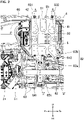
- Fig. 1 is a bottom view exemplifying a lower structure of an electric vehicle 1 according to the present disclosure.
- Fig. 2 is a bottom view exemplifying a lower structure around a battery unit 4
- Fig. 3 is a perspective view exemplifying the lower structure around the battery unit 4.
- Fig. 2 is an enlarged view of an arrangement position of the battery unit 4 in Fig. 1
- Fig. 3 is a perspective view in which the lower structure of the electric vehicle 1 is seen obliquely downward from the above in a state where a floor panel 61 is removed.
- Fig. 4 is a cross-sectional view that is taken along A-A in Fig. 2
- FIG. 5 is a cross-sectional view that is taken along B-B in Fig. 2 .
- Fig. 4 illustrates a transverse section passing through a first outer fastener 831 and a first inner fastener 841, which will be described below
- Fig. 5 illustrates a transverse section passing through a second outer fastener 832 and a second inner fastener 842, which will be described below.
- front refers to "front” in a vehicle front-rear direction that is a front-rear direction of the electric vehicle 1
- rear refers to “rear” in the vehicle front-rear direction.
- up refers to “up” in a vehicle height direction that is a height direction of the electric vehicle 1
- down refers to "down” in the vehicle height direction.
- the vehicle front-rear direction may simply be referred to as the "front-rear direction”
- the vehicle height direction may be referred to as an "up-down direction”.
- upward (an upper side) in the vehicle height direction may be referred to as “upward in the vehicle (a vehicle upper side)” or simply “upward (the upper side)
- downward (a lower side) in the vehicle height direction may be referred to as “downward in the vehicle (a vehicle lower side)” or simply “downward (the lower side)
- front (a front side) in the vehicle front-rear direction may be referred to as "front in the vehicle (a vehicle front side)” or simply “front (the front side)”
- rearward (a rear side) in the vehicle front-rear direction may be referred to as "rearward in the vehicle (a vehicle rear side) " or simply “rear (the rear side)”.
- left and right in the following description are also defined with reference to the electric vehicle 1. That is, in the following description, “left” refers to a left side in a vehicle width direction at the time when the electric vehicle 1 is seen from the rear side toward the front side, and “right” refers to a right side at the time when the vehicle is seen from the rear side toward the front side.
- the vehicle width direction may be referred to as the "right-left” direction.
- a direction away from a central portion of the electric vehicle 1 may be referred to as "outward in the vehicle (a vehicle outer side) “ or simply “outside (an outer side)”
- a direction that approaches the central portion of the electric vehicle 1 may be referred to as "inward in the vehicle (a vehicle inner side)” or simply “inward (an inner side)”.
- the electric vehicle 1 exemplified in Fig. 1 includes: elements associated with a body of the electric vehicle 1 such as the floor panel 61 and the floor tunnel 62; and elements associated with power of the electric vehicle 1 such as an electric drive system 3 and the battery unit 4.
- the electric vehicle 1 includes the floor panel 61, the floor tunnel 62, a tunnel side frame 63, a side sill 64, tunnel crossmembers 651, 652, a floor side frame 66, and a floor crossmember 67.
- the floor panel 61 is disposed in a lower portion of the electric vehicle 1.
- the floor panel 61 constitutes a cabin floor of the electric vehicle 1.
- the floor panel 61 expands in the front-rear direction and the vehicle width direction in a manner to connect the two side sills 64 that are disposed in both side portions in the vehicle width direction of the electric vehicle 1.
- the floor panel 61 is provided with the floor tunnel 62 that extends in the vehicle front-rear direction.
- This floor tunnel 62 is provided in a central portion in the vehicle width direction of the floor panel 61.
- the floor tunnel 62 constitutes an accommodation space for an exhaust pipe 12 and a propeller shaft 52.
- the floor tunnel 62 bulges above the floor panel 61 as illustrated in Fig. 4 or Fig. 5 , and extends in the front-rear direction as illustrated in Fig. 1 .
- a right and left pair of the tunnel side frames 63 is respectively disposed in both side portions in the vehicle width direction of the floor tunnel 62.
- Each of the tunnel side frames 63 is arranged below the floor panel 61.
- Each of the tunnel side frames 63 is a highly rigid frame and extends in the front-rear direction along the floor tunnel 62.
- each of the tunnel side frames 63 is formed to have a substantially hat-shaped cross section, an opening of which faces upward, and is joined to a lower surface of respective one of the both of the side portions in the vehicle width direction of the floor tunnel 62.
- each of the tunnel side frames 63 has a first vertical wall portion 63a and a second vertical wall portion 63b.
- the first tunnel crossmember 651 and an attachment bracket 8 can be connected to a lower wall portion that connects the first vertical wall portion 63a and the second vertical wall portion 63b in the tunnel side frame 63.
- the first vertical wall portion 63a faces a vehicle inner side of the floor tunnel 62.
- the first vertical wall portion 63a is inclined inward in the vehicle to the vehicle upper side.
- the second vertical wall portion 63b faces a vehicle outer side of the floor tunnel 62.
- the second vertical wall portion 63b is inclined outward in the vehicle to the vehicle upper side.
- the second vertical wall portion 63b is formed to be inclined more steeply than the first vertical wall portion 63a with respect to a vehicle up-down direction.
- an acute inclination angle is set as a first inclination angle ⁇ 1
- an acute inclination angle is set as a second inclination angle ⁇ 2
- the second inclination angle ⁇ 2 is set to be larger than the first inclination angle ⁇ 1 ( ⁇ 2 > ⁇ 1). That is, the substantially hat-shaped cross section of the tunnel side frame 63 is bilaterally asymmetrical.
- the tunnel crossmembers 651, 652 are attached to specified positions in the floor tunnel 62, more specifically, two positions in a rear portion of the floor tunnel 62.
- the first tunnel crossmember 651 on a front side is connected to the tunnel side frame 63 and extends in the vehicle width direction in a manner to connect the two tunnel side frames 63 (partially illustrated in Fig. 4 ).
- the first tunnel crossmember 651 is located behind a transmission support member 21, which will be described below.
- the second tunnel crossmember 652 on a rear side also extends in the vehicle width direction in the manner to connect the two tunnel side frames 63.
- the first tunnel crossmember 651 has a greater width in the front-rear direction than the second tunnel crossmember 652.
- the floor side frame 66 is arranged below the floor panel 61 in the vehicle and is arranged on the outer side in the vehicle width direction of the tunnel side frame 63.
- the floor side frame 66 is arranged on the inner side in the vehicle width direction of the side sill 64. Accordingly, the floor side frame 66 is disposed between the side sill 64 and the tunnel side frame 63.
- the floor side frame 66 is a highly rigid frame.
- the floor side frame 66 is formed to have a substantially hat-shaped cross section, an opening of which faces upward, and is joined to a lower surface of each of both side portions in the vehicle width direction of the floor panel 61.
- the floor side frame 66 is located in the middle between the side sill 64 and the tunnel side frame 63 in the vehicle width direction. From the above position, the floor side frame 66 extends obliquely outward in the vehicle width direction to the rear of the electric vehicle 1, and abuts an inner side of the side sill 64 at a position near a central portion in the front-rear direction of the floor panel 61.
- the floor side frame 66 that abuts the inner side of the side sill 64 extends straight toward the rear of the electric vehicle 1 along the inner side of the side sill 64. As exemplified in Fig. 4 and Fig. 5 , the floor side frame 66, which abuts the inner side of the side sill 64, is located closer to the side sill 64 than the tunnel side frame 63 in the vehicle width direction.
- FIG. 4 and the like only illustrate the floor side frame 66 on a left side of the floor tunnel 62, the floor side frame 66 is also disposed on a right side of the floor tunnel 62.
- the two floor side frames 66 are disposed in a bilaterally-symmetrical manner.
- the floor crossmember 67 is disposed on the floor panel 61.
- the floor crossmember 67 is disposed to extend across both of the side portions in the vehicle width direction of the floor panel 61 with the floor tunnel 62 being interposed therebetween.
- the floor crossmember 67 extends in the vehicle width direction in a manner to connect the side sill 64 provided on the left side of the electric vehicle 1 and the side sill 64 provided on the right side of the electric vehicle 1 with the floor tunnel 62 being interposed therebetween.
- the floor crossmember 67 constitutes a closed cross section that extends in the vehicle width direction, and can support right and left seats that are disposed in a front side of the cabin.
- the floor crossmember 67 has a hollow first component 671 that extends in the vehicle width direction and a second component 672 that is provided in each of right and left end portions (the left end portion in the illustrated example) of the first component 671.
- the second component 672 is arranged right above the floor side frame 66 along the vehicle height direction.
- two vulnerable portions 673, 674 are formed in a vehicle lower side of the floor crossmember 67, and the two vulnerable portions 673, 674 are configured to promote bending of the floor crossmember 67 to the vehicle upper side when a load is input from a side of the electric vehicle 1 (an outer side of the electric vehicle 1). Both of the two vulnerable portions 673, 674 are arranged to be closer to the floor side frame 66 than the tunnel side frame 63 in the vehicle width direction.
- the first vulnerable portion 673 that is formed in the first component 671 is disposed near a corner (a corner on the vehicle outer side) 4b on the floor side frame 66-side of the battery unit 4.
- the second vulnerable portion 674 that is formed in the second component 672 is disposed near the floor side frame 66 that is disposed on the vehicle outer side of the battery unit 4.
- both of the first vulnerable portion 673 and the second vulnerable portion 674 are formed to promote deformation of a portion on the vehicle lower side therein.
- the portions in particular, portions provided with the first vulnerable portion 673 and the second vulnerable portion 674
- the portions on the vehicle lower side in the floor crossmember 67 are deformed in a manner to approach each other in the vehicle width direction.
- This deformation corresponds to deformation that shrinks and crushes each of the first vulnerable portion 673 and the second vulnerable portion 674 in the vehicle width direction.
- the first vulnerable portion 673 includes a notch that is provided in a lower half portion of the first component 671 in the floor crossmember 67. By providing the notch, it is possible to promote the deformation that crushes and shrinks the lower half portion of the first component 671.
- the second vulnerable portion 674 has a bead shape that is provided in a lower half portion of the second component 672 in the floor crossmember 67. By providing the bead shape, it is possible to promote the deformation that crushes and shrinks the lower half portion of the second component 672.
- the electric vehicle 1 includes, as elements associated with a power transmission system, an engine, which is not illustrated, a transmission 2, and the electric drive system 3.
- the electric vehicle 1 is a four-wheel-drive vehicle that is based on a front-engine, rear-wheel-drive vehicle.
- the electric vehicle 1 further includes a transfer 51 and the propeller shaft 52 as the elements associated with the power transmission system.
- the engine is a gasoline engine that is supplied with fuel at least containing gasoline, or a diesel engine that is supplied with diesel fuel.
- the engine is of a spark-ignition type or a compression-ignition type.
- a type of the engine is not particularly limited.
- the engine is installed in a so-called vertically-arranged manner in an engine compartment that is provided in a front portion of the electric vehicle 1.
- a fuel tank 11 is disposed in a rear portion of the electric vehicle 1. The fuel tank 11 stores the fuel to be supplied to the engine.
- the exhaust pipe 12 for discharging exhaust gas is connected to the engine.
- the exhaust pipe 12 is disposed under the floor panel 61 that constitutes the cabin floor of the electric vehicle 1.
- the exhaust pipe 12 extends from the engine compartment towards the rear of the electric vehicle 1.
- a catalytic converter 13 is disposed in the middle of the exhaust pipe 12.
- the electric drive system 3 includes an electric motor 30, an inverter (not illustrated), and the battery unit 4.
- the electric motor 30 is disposed on an output shaft of the engine.
- the electric motor 30 is interposed between the engine and the transmission 2.
- the electric motor 30 outputs drive torque for travel of the vehicle during power running, and also performs regeneration to apply a braking force to the vehicle.
- the transmission 2 is an automatic transmission that includes at least one planetary gear mechanism.
- the transmission 2 is not limited to the automatic transmission.
- the transmission 2 is joined to the output shafts of the engine and the electric motor 30.
- the transmission 2 changes and outputs the torque of the engine and/or the electric motor 30.
- the transmission 2 is disposed behind the electric motor 30. As illustrated in Fig. 1 and Fig. 2 , the electric motor 30 and the transmission 2 are disposed on the inside of the floor tunnel 62. In a front portion of the floor tunnel 62, a case of the transmission 2 extends in the front-rear direction along the floor tunnel 62.
- the transfer 51 is connected to an output shaft of the transmission 2.
- the transfer 51 is disposed on the inside of the floor tunnel 62.
- a case of the transfer 51 is integrated with the case of the transmission 2.
- the case of the transfer 51 and the case of the transmission 2, which are integrated, will collectively be referred to as the "case of the transmission 2".
- a rear end portion of the case of the transmission 2, more precisely, the case of the transfer 51 is supported by the transmission support member 21.
- the transmission support member 21 extends in the vehicle width direction in a manner to stretch between the two tunnel side frames 63.
- the propeller shaft 52 is connected to the transfer 51.
- the transfer 51 distributes the torque of the engine and/or the electric motor 30 to front wheels and rear wheels.
- the propeller shaft 52 extends from the transfer 51 to the rear of the electric vehicle 1.
- the propeller shaft 52 is connected to a rear driveshaft, which is joined to the right and left rear wheels, via a rear differential gear, which is not illustrated.
- the battery unit 4 is electrically connected to the electric motor 30 via the inverter.
- the battery unit 4 supplies electric power for driving the electric motor 30 thereto.
- the battery unit 4 is charged during the regeneration of the electric motor 30.
- the inverter supplies the electric power of the battery unit 4 to the electric motor 30 during the power running, and transmits the electric power generated by the electric motor 30 to the battery unit 4 during the regeneration.
- the battery unit 4 has a substantially rectangular shape in a bottom view.
- the battery unit 4 has a battery module 41 and a junction box 42.
- the junction box 42 is disposed in a front end portion of the battery unit 4.
- the battery module 41 is disposed behind the junction box 42.
- the battery unit 4 is arranged under the floor panel 61 in the vehicle. In addition, the battery unit 4 is arranged between the tunnel side frame 63 and the floor side frame 66 in the vehicle width direction.
- the battery unit 4 is disposed on the left side of the floor tunnel 62. Further in detail, at a position behind the transmission 2 and in front of the fuel tank 11, the battery unit 4 is disposed between the tunnel side frame 63 and the floor side frame 66. The battery unit 4 is disposed on an opposite side of the floor tunnel 62 from the exhaust pipe 12 and the catalytic converter 13 of the engine. This disposition structure allows the electric drive system 3 to be located away from a heat source.
- a DC/DC converter 32 illustrated in Fig. 1 or Fig. 2 constitutes a part of the electric drive system 3. On the left side of the floor tunnel 62, the DC/DC converter 32 is disposed on the left side of the transmission 2 and in front of the battery unit 4.
- the floor side frame 66 is disposed to abut the side sill 64. Accordingly, in the rear portion of the floor panel 61, a distance in the vehicle width direction between the tunnel side frame 63 and the floor side frame 66 is long.
- the large-sized battery unit 4 can be disposed in this large space. Thus, capacity of the battery unit 4 is relatively large.
- the electric vehicle 1 also includes the attachment bracket 8 for connecting the battery unit 4 to the body.
- the battery unit 4 is attached to the floor panel 61 by this attachment bracket 8.
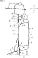
- Fig. 6 is a perspective view exemplifying the battery unit 4 and the attachment bracket 8 that are seen from the vehicle inner side
- Fig. 7 is a perspective view exemplifying the battery unit 4 and the attachment bracket 8 that are seen from the vehicle outer side
- Fig. 8 is a view exemplifying a structure of the floor crossmember 67
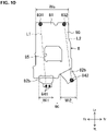
- Fig. 10 is a view for explaining a width of the attachment bracket 8.
- the attachment bracket 8 is formed to extend from the tunnel side frame 63 to the floor side frame 66 along the vehicle width direction.
- the attachment bracket 8 can connect the battery unit 4 to the tunnel side frame 63 and the floor side frame 66.
- the battery unit 4 is attached to the floor panel 61 via the tunnel side frame 63 and the floor side frame 66.
- the attachment bracket 8 has a hat-shaped transverse section, an opening of which faces upward. As illustrated in Fig. 6 and Fig. 7 , the attachment bracket 8 has a lower wall portion 80, an outer vertical wall portion 81, an inner vertical wall portion 82, outer fasteners 831, 832, and inner fasteners 841, 842.
- the lower wall portion 80 supports a bottom portion of the battery unit 4.
- this lower wall portion 80 may be formed in a rectangular shape that extends along the vehicle front-rear direction and the vehicle width direction and, when seen in a cross section along the vehicle width direction (a cross section that is perpendicular to the vehicle front-rear direction), extends from a position near the tunnel side frame 63 to a position near the floor side frame 66.
- the lower wall portion 80 is located under the battery unit 4 and expands in a manner to cover a bottom surface of the battery unit 4.
- the lower wall portion 80 supports the battery unit 4 from below.
- an opening 85 that may be formed in a rectangular shape is provided in a central portion of the lower wall portion 80. This opening 85 contributes to a reduction in weight of the lower wall portion 80, and thus the attachment bracket 8.
- the outer vertical wall portion 81 extends upward from an end portion (a left end portion in the illustrated example) on the vehicle outer side of the lower wall portion 80 and is connected to the floor side frame 66.
- the outer vertical wall portion 81 is located on the outer side (that is, the left side) in the vehicle width direction of the lower wall portion 80 and continues from a left edge of the lower wall portion 80.
- the outer vertical wall portion 81 expands in the front-rear direction and extends in the up-down direction.
- An upper end portion of the outer vertical wall portion 81 is bent in a flange shape that protrudes outward in the vehicle width direction. While the first outer fastener 831 is inserted in a front portion of the upper end portion, a second outer fastener 832 is inserted in a rear portion of the upper end portion. The first outer fastener 831 and the second outer fastener 832 are inserted in the upper end portion of the outer vertical wall portion 81 from below, and are each fastened to the floor side frame 66. Due to such fastening, the outer vertical wall portion 81 is connected to the floor side frame 66.
- the inner vertical wall portion 82 extends upward from an end portion (a right end portion in the illustrated example) on the vehicle inner side of the lower wall portion 80 and is connected to the tunnel side frame 63.
- the inner vertical wall portion 82 is located on the inner side (that is, the right side) in the vehicle width direction of the lower wall portion 80 and continues from a right edge of the lower wall portion 80.
- the inner vertical wall portion 82 expands in the front-rear direction and extends in the up-down direction. As exemplified in Fig.
- a width (hereinafter referred to as an "inner width”) Wi in the vehicle front-rear direction of the inner vertical wall portion 82 is shorter than a width (hereinafter referred to as an "outer width") Wo in the vehicle front-rear direction of the outer vertical wall portion 81.
- the inner vertical wall portion 82 has: a first inner vertical wall portion 82a that is connected to the tunnel side frame 63; and a second inner vertical wall portion 82b that is arranged in line with the first inner vertical wall portion 82a in the vehicle front-rear direction and connected to the tunnel side frame 63.
- the first inner vertical wall portion 82a and the second inner vertical wall portion 82b are configured as mutually independent components and are arranged in line with a space being interposed therebetween in the vehicle front-rear direction.
- the first inner vertical wall portion 82a is arranged on the vehicle front side when compared to the second inner vertical wall portion 82b.
- the first inner vertical wall portion 82a is located on the inner side (that is, the right side) in the vehicle width direction of the lower wall portion 80 and continues from a front portion of the right edge of the lower wall portion 80.
- the first inner vertical wall portion 82a expands in the front-rear direction and extends in the up-down direction.
- an upper end portion of the first inner vertical wall portion 82a is bent in a flange shape that protrudes outward in the vehicle width direction.
- a front and rear pair of the first inner fasteners 841 is inserted in the upper end portion thereof.
- the first inner fasteners 841 jointly fasten the upper end portion of the first inner vertical wall portion 82a and the first tunnel crossmember 651 (also see Fig. 3 ).
- the first tunnel crossmember 651 is connected to the tunnel side frame 63. Accordingly, due to this joint fastening, the first inner fasteners 841 are connected to the tunnel side frame 63 via the first tunnel crossmember 651.
- the upper end portion of the first inner vertical wall portion 82a is located on a center side in the vehicle width direction from the tunnel side frame 63.
- the first inner vertical wall portion 82a is located at the substantially same position as the tunnel side frame 63 in the vehicle width direction. Since the first inner vertical wall portion 82a is located on the center side in the vehicle width direction, a right portion of the battery unit 4 can be located on the center side in the vehicle width direction, and the right portion of the battery unit 4 is adjacent to the left portion of the floor tunnel 62. That is, the battery unit 4 becomes large in size, and accordingly, the capacity of the battery unit 4 becomes large.
- the attachment bracket 8 is configured that a straight line L1 connecting the first outer fastener 831 and the first inner fastener 841 does not cross the opening 85 provided in the lower wall portion 80.
- the second inner vertical wall portion 82b is arranged on the vehicle rear side when compared to the first inner vertical wall portion 82a.
- the second inner vertical wall portion 82b is located on the inner side (that is, the right side) in the vehicle width direction of the lower wall portion 80 and continues from a rear portion of the right edge of the lower wall portion 80.
- the second inner vertical wall portion 82b expands in the front-rear direction and extends in the up-down direction.
- a dimension in the vehicle height direction of the second inner vertical wall portion 82b is slightly shorter than a dimension in the vehicle height direction of the first inner vertical wall portion 82a.
- an upper end portion of the second inner vertical wall portion 82b is bent in a flange shape that protrudes outward in the vehicle width direction.
- a second inner fastener 842 is inserted in the upper end portion thereof. As illustrated in Fig. 5 , the second inner fastener 842 jointly fastens the upper end portion of the second inner vertical wall portion 82b and the tunnel side frame 63. Due to this joint fastening, the second inner fastener 842 is connected to the tunnel side frame 63.
- the attachment bracket 8 is configured that a straight line L2 connecting the second outer fastener 832 and the second inner fastener 842 does not cross the opening 85 provided in the lower wall portion 80.
- a connected position between the second inner fastener 842 and the upper end portion of the second inner vertical wall portion 82b is arranged on the vehicle inner side when compared to a connected position between the first inner fasteners 841 and the upper end portion of the first inner vertical wall portion 82a.
- a connected position between the inner vertical wall portion 82 and the tunnel side frame 63 is located higher in the vehicle than a connected position between the outer vertical wall portion 81 and the floor side frame 66.
- a heights (hereinafter also referred to as “inner heights”) Hi1, Hi2 of the connected positions between the inner vertical wall portion 82 and the tunnel side frame 63 are located higher in the vehicle than a height (hereinafter also referred to as an “outer height") Ho of the connected position between the outer vertical wall portion 81 and the floor side frame 66.
- the outer height Ho can be a height that is seen in a transverse section passing through the first outer fastener 831 or a transverse section passing through the second outer fastener 832. Since the outer heights Ho that are seen in the two transverse sections are substantially the same as each other, no distinction will be made therebetween in the following description.
- the inner heights Hi1, Hi2 can be the inner height Hi1 that is seen in a transverse section passing through the first inner fasteners 841 as illustrated in Fig. 4 , or the inner height Hi2 that is seen in a transverse section passing through the second inner fastener 842 as illustrated in Fig. 5 .
- the inner height Hi1 that is seen in the transverse section passing through the first inner fastener 841 and the first outer fastener 831 is slightly higher than the inner height Hi2 that is seen in the transverse section passing through the second inner fastener 842 and the second outer fastener 832 (that is, Hi1 > Hi2).
- both of the two inner heights Hi1, Hi2 are configured to be higher than the outer height Ho (that is, Hi1 > Ho and Hi2 > Ho).
- the inner height Hi1 is higher than the outer height Ho.
- the inner height Hi2 is higher than the outer height Ho.
- the length in the vehicle height direction of the inner vertical wall portion 82 is longer than the length in the vehicle height direction of the outer vertical wall portion 81.
- both the first inner vertical wall portion 82a and the second inner vertical wall portion 82b extend upward in the vehicle to be longer than the outer vertical wall portion 81.
- the battery unit 4 according to this embodiment is accommodated in an accommodation space that is defined by the attachment bracket 8 configured as described above, the second vertical wall portion 63b of the tunnel side frame 63, the floor side frame 66, and the floor panel 61.
- the second vertical wall portion 63b is provided to face a corner 4a on the vehicle inner side in an upper end portion of the battery unit 4 along the vehicle width direction.
- a height position of the corner 4a on the vehicle inner side is higher than a connected position between the second inner vertical wall portion 82b and the tunnel side frame 63.
- the height position of the corner 4a on the vehicle inner side is slightly lower than an upper end portion of the second vertical wall portion 63b.
- the floor side frame 66 is provided to face a corner 4b on the vehicle outer side in the upper end portion of the battery unit 4 along the vehicle width direction.
- a height position of the corner 4b on the vehicle outer side is higher than the connected position between the outer vertical wall portion 81 and the floor side frame 66.
- the height position of the corner 4b on the vehicle outer side is slightly lower than an upper end portion of the floor side frame 66.
- an empty space 86 is formed between the upper end portion of the battery unit 4 and the lower surface of the floor panel 61 by notching the corner 4b on the vehicle outer side. As illustrated in Fig. 8 , the empty space 86 is arranged below the second vulnerable portion 674.
- pipes 91 On the vehicle outer side (the left side in the illustrated example) of the empty space 86, pipes 91, each of which extends in the vehicle front-rear direction, are arranged. These pipes 91 are attached to the floor side frame 66 via a bracket 92. Since the corner 4b is notched, an upper surface near the corner 4b is located lower in the vehicle than the pipes 91. For example, the fuel can be distributed through the pipes 91.
- the pipes 91 are arranged between the lower surface of the floor panel 61 and a flange 41a that protrudes outward in the vehicle in the battery unit 4.
- the pipes 91 are arranged between the empty space 86 and the floor side frame 66.
- the pipes 91 are also arranged under the first vulnerable portion 673.
- the floor side frame 66 when the floor side frame 66 is arranged on the vehicle outer side to be close to the side sill 64, it is possible to increase the distance between the tunnel side frame 63 and the floor side frame 66.
- the increase in the distance between the tunnel side frame 63 and the floor side frame 66 leads to enlargement of the battery unit 4 and improvement in the capacity of the battery unit 4.
- a side surface (in particular, a left surface facing the vehicle outer side) of the battery unit 4 also becomes close to the side sill 64.
- the side surface of the battery unit 4 is brought close to the side sill 64, it becomes disadvantageous to a lateral collision.
- the battery capacity of the battery unit 4 is improved, and the battery unit 4 is protected during a lateral collision without causing the weight increase, the cost increase, and the like.
- the connected position between the inner vertical wall portion 82 and the tunnel side frame 63 is located higher in the vehicle than the connected position between the outer vertical wall portion 81 and the floor side frame 66.
- Fig. 9 includes transition views exemplifying oscillation of the battery unit 4 during the lateral collision of the electric vehicle 1.
- Step S1 illustrates a state where the lateral collision occurs and the attachment bracket 8 starts oscillating.
- the connected position between the outer vertical wall portion 81 and the floor side frame 66 is located lower in the vehicle than the connected position between the inner vertical wall portion 82 and the tunnel side frame 63. Accordingly, in the case where the load is input from the side of the electric vehicle 1 (in particular, as indicated by an arrow F, in the case where the load is input from the side to a position above the floor panel 61 in the vehicle), the outer vertical wall portion 81 is more likely to receive the load in a direction toward the vehicle lower side than the inner vertical wall portion 82. By displacing the outer vertical wall portion 81 toward the vehicle lower side by such a load, the attachment bracket 8 can oscillate like a swing with the connected position between the inner vertical wall portion 82 and the tunnel side frame 63 being a fulcrum P.
- Step S2 illustrates a state where the oscillation of the attachment bracket 8 has progressed.
- the battery unit 4 which is supported by the lower wall portion 80 of the attachment bracket 8, can also oscillate to the vehicle lower side. This oscillation causes the battery unit 4 to be inclined obliquely in a manner to displace the portion thereof on the vehicle outer side downward.
- the floor crossmember 67 When the load is input from the side of the electric vehicle 1, the floor crossmember 67 receives such a load that bends the floor crossmember 67.
- the vulnerable portions 673, 674 that are configured as described above, the floor crossmember 67 can be bent in the manner to protrude upward in the vehicle.
- the battery unit 4 oscillates to the vehicle lower side, the floor crossmember 67 protrudes upward in the vehicle. In this way, as illustrated in step S2, it is possible to suppress interference between the floor crossmember 67 and the battery unit 4. This is advantageous for the favorable protection of the battery unit 4.
- step S2 the pipes 91 are displaced toward the vehicle inner side.
- the empty space 86 that is configured as described above is provided.
- the pipes 91 can easily be guided to the vehicle upper side at the time when an upper surface around this corner 4b and the pipes 91 come into contact with each other.
- Step S3 illustrates a state where the oscillation of the attachment bracket 8 has further progressed.
- the battery unit 4 can be evacuated to the vehicle lower side.
- evacuating the battery unit 4 to the vehicle lower side it is possible to avoid interference between the battery unit 4 and a vehicle component J, which is formed when the side sill 64 and the like are crushed toward the vehicle inner side, and to favorably protect the battery unit 4.
- the battery unit 4 can favorably be protected even when the floor side frame 66 is arranged on the vehicle outer side and brought close to the side sill 64, in this electric vehicle 1, it is possible to simultaneously improve the battery capacity and protect the battery during the lateral collision without causing the weight increase, the cost increase, and the like.
- the corner 4a on the vehicle inner side of the battery unit 4 possibly comes into contact with the second vertical wall portion 63b.
- the second vertical wall portion 63b is steeply inclined as described above, compared to a configuration that the second vertical wall portion 63b extends in parallel with the vehicle up-down direction, for example, it is possible to smoothly guide the corner 4a, which has contacted the second vertical wall portion 63b, to the vehicle lower side. This is advantageous for the protection of the battery unit 4.
- the inner width Wi which is the width in the vehicle front-rear direction of the inner vertical wall portion 82
- the outer width Wo which is the width in the vehicle front-rear direction of the outer vertical wall portion 81
- the inner vertical wall portion 82 is constructed of the first inner vertical wall portion 82a and the second inner vertical wall portion 82b.
- An inner vertical wall portion 82' may be constructed of a single inner vertical wall portion like an attachment bracket 8' illustrated in Fig. 11 .
- an inner width Wi' corresponds to a width in the vehicle front-rear direction of the single inner vertical wall portion.
- this inner width Wi' is set to be shorter than an outer width Wo', similar to the embodiment, it is possible to promote oscillation of the attachment bracket 8' and thus to favorably protect the battery unit that is supported by a lower wall portion 80' thereof.
- an outer vertical wall portion 81' is constructed of a single plate-shaped body.
- the outer vertical wall portion 81' may be constructed of two or more plate-shaped bodies.
- the technique disclosed herein is not limited to the application to the four-wheel-drive vehicle.
- the technique disclosed herein may be applied to the front-engine, rear-wheel-drive vehicle.
Landscapes
- Engineering & Computer Science (AREA)
- Chemical & Material Sciences (AREA)
- Transportation (AREA)
- Mechanical Engineering (AREA)
- Combustion & Propulsion (AREA)
- Aviation & Aerospace Engineering (AREA)
- Chemical Kinetics & Catalysis (AREA)
- Electrochemistry (AREA)
- General Chemical & Material Sciences (AREA)
- Power Engineering (AREA)
- Sustainable Energy (AREA)
- Sustainable Development (AREA)
- Life Sciences & Earth Sciences (AREA)
- Body Structure For Vehicles (AREA)
- Arrangement Or Mounting Of Propulsion Units For Vehicles (AREA)
Abstract
Description
- A technique disclosed herein relates to a lower structure of an electric vehicle.
- For example, a battery mounting structure for a vehicle is disclosed in Patent document 1. More specifically, this patent document 1 discloses a vehicle that includes: an attachment bracket that supports a battery from below; a tunnel side frame that is arranged at both of right and left ends of a floor tunnel (a tunnel section); a floor side frame (a floor frame) that is arranged under a floor panel in the vehicle and is arranged on a vehicle outer side from the tunnel side frame.
- The attachment bracket according to Patent document 1 is formed to extend from the tunnel side frame to the floor side frame and connects the tunnel side frame and the floor side frame to the battery. In this way, the battery can be disposed under the floor panel.
- [Patent document 1]
JP-A-2017-77840 - In the case where the vehicle as disclosed in Patent document 1 is used, the floor side frame is arranged on the vehicle outer side and is brought close to a side sill, so as to increase a distance between the tunnel side frame and the floor side frame. The increase in the distance between the tunnel side frame and the floor side frame leads to enlargement of the battery and improvement in battery capacity.
- However, in the case where the battery capacity is improved as described above, a side surface (in particular, the side surface facing the vehicle outer side) of the battery is also brought close to the side sill. In the case where the side surface of the battery is brought close to the side sill, it becomes disadvantageous with respect to a lateral collision.
- As preparation for the lateral collision, it is considered to provide a hollow energy absorbing member on a side of the battery, for example. However, new provision of the energy absorbing member increases weight, cost, and the like, and thus is inconvenient.
- A technique disclosed herein has been made in view of such points and therefore has a purpose of simultaneously improving battery capacity and protecting a battery during a lateral collision without causing a weight increase, a cost increase, and the like.
- A first aspect of the present disclosure relates to a lower structure of an electric vehicle. This electric vehicle includes: a floor panel that is provided with a floor tunnel extending in a vehicle front-rear direction; a tunnel side frame that is arranged below the floor panel in the vehicle and is arranged in both side portions in a vehicle width direction of the floor tunnel; a floor side frame that is arranged below the floor panel in the vehicle and is arranged on an outer side in the vehicle width direction of the tunnel side frame; a battery unit that is arranged below the floor panel in the vehicle and is arranged between the tunnel side frame and the floor side frame in the vehicle width direction; and an attachment bracket that is formed to extend from the tunnel side frame to the floor side frame along the vehicle width direction and connects the battery unit to the tunnel side frame and the floor side frame.
- According to the first aspect, the attachment bracket has: a lower wall portion that supports a bottom portion of the battery unit; an outer vertical wall portion that extends upward from an end portion on a vehicle outer side of the lower wall portion and is connected to the floor side frame; and an inner vertical wall portion that extends upward from an end portion on a vehicle inner side of the lower wall portion and is connected to the tunnel side frame. A connected position between the inner vertical wall portion and the tunnel side frame is located higher in the vehicle than a connected position between the outer vertical wall portion and the floor side frame.
- Here, the inner vertical wall portion and the tunnel side frame may directly be connected by a fastener such as a bolt or may indirectly be connected via a member such as a tunnel crossmember. The same applies to the outer vertical wall portion and the floor side frame.
- According to the first aspect, the connected position between the outer vertical wall portion and the floor side frame is located lower in the vehicle than the connected position between the inner vertical wall portion and the tunnel side frame. In this case, when a load is input from a side of the vehicle, it is possible to set the connected position between the outer vertical wall portion and the floor side frame to be lower than a load input position. Accordingly, when the load is input from the side of the vehicle, the outer vertical wall portion according to the first aspect is more likely to receive the load in a direction toward a vehicle lower side than the inner vertical wall portion. By displacing the outer vertical wall portion toward the vehicle lower side by such a load, the attachment bracket can oscillate like a swing with the connected position between the inner vertical wall portion and the tunnel side frame being a fulcrum. With the oscillation of the attachment bracket, the battery unit, which is supported by the lower wall portion, can also oscillate to the vehicle lower side. By evacuating the battery unit to the vehicle lower side with the oscillation thereof, it is possible to favorably protect the battery unit.
- In a point that the battery unit can favorably be protected even when the floor side frame is arranged on the vehicle outer side and brought close to a side sill, in the first aspect, it is possible to simultaneously improve battery capacity and protect a battery during a lateral collision without causing a weight increase, a cost increase, and the like.
- According to a second aspect of the present disclosure, a width in the vehicle front-rear direction of the inner vertical wall portion may be shorter than a width in the vehicle front-rear direction of the outer vertical wall portion.
- According to the second aspect, since the width of the inner vertical wall portion is reduced, it is possible to promote the oscillation of the attachment bracket with the connected position between the inner vertical wall portion and the tunnel side frame being the fulcrum. This is useful for protection of the battery. More generally, the inner vertical wall portion may have a lower rigidity and/or lower stiffness, in particular a lower bending resistance, than the outer vertical wall portion to allow the attachment bracket swing about the point of connection to the tunnel side frame when the floor side frame is deformed and/or displaced inwardly due to a lateral collision. Such reduced rigidity and/or reduced stiffness and/or reduced strength may be achieved by the aforementioned difference in width and, in the alternative or in addition by means of cutouts and/or different shapes and/or different materials and/or different thicknesses.
- According to a third aspect of the present disclosure, the inner vertical wall portion may have: a first inner vertical wall portion that is connected to the tunnel side frame; and a second inner vertical wall portion that is arranged in line with the first inner vertical wall portion in the vehicle front-rear direction and is connected to the tunnel side frame. A total length as a sum of a width in the vehicle front-rear direction of the first inner vertical wall portion and a width in the vehicle front-rear direction of the second inner vertical wall portion may be shorter than the width in the vehicle front-rear direction of the outer vertical wall portion.
- According to the third aspect, since the inner vertical wall portion is constructed of the first and second inner vertical wall portions, it is possible to connect the attachment bracket to the tunnel side frame at least at two positions that are mutually separated in the front-rear direction. In this way, it is possible to stabilize the connection between the inner vertical wall portion and the tunnel side frame. Furthermore, according to the third aspect, a clearance is formed between the first inner vertical wall portion and the second inner vertical wall portion. Accordingly, the width of the entire inner vertical wall portion can easily be set to be short, which is advantageous for promotion of the oscillation of the attachment bracket.
- According to a fourth aspect of the present disclosure, the tunnel side frame may have: a first vertical wall portion that faces a vehicle inner side of the floor tunnel and is inclined inward in the vehicle to the vehicle upper side; and a second vertical wall portion that faces a vehicle outer side of the floor tunnel and is inclined outward in the vehicle to the vehicle upper side. The second vertical wall portion may be provided to face a corner on the vehicle inner side in an upper end portion of the battery unit along the vehicle width direction, and may be formed to be inclined with respect to a vehicle up-down direction more steeply than the first vertical wall portion.
- In the case where the oscillation of the attachment bracket progresses, the corner on the vehicle inner side of the battery unit possibly comes into contact with the second vertical wall portion. In view of the above, the second vertical wall portion is relatively steeply inclined as in the fourth aspect. As a result, compared to a configuration that the second vertical wall portion extends in parallel with the vehicle up-down direction, for example, it is possible to smoothly guide the corner, which has contacted the second vertical wall portion, to the vehicle lower side. This is advantageous for the protection of the battery unit.
- According to a fifth aspect of the present disclosure, the electric vehicle includes a floor crossmember that is arranged on the floor panel and is disposed to extend across both side portions in the vehicle width direction of the floor panel. A vulnerable portion may be formed in a vehicle lower side of the floor crossmember, and the vulnerable portion may be configured to promote bending of the floor crossmember to the vehicle upper side when a load is input from a side of the vehicle. More generally, the floor crossmember may be configured to buckle upwardly upon receiving a compression force in the vehicle width direction upon a lateral collision, wherein, e.g., the floor crossmember may have, in addition or in the alternative to the aforementioned vulnerable portion, a specific cross-sectional shape providing for different bending strengths in different directions and promoting buckling upwardly. Such specific cross-sectional shape may include, e.g., different wall thicknesses in different cross-sectional sectors and/or preset deformations dimples to achieve a reduced buckling stiffness against buckling away from the battery unit.
- According to the fifth aspect, when the load is input from the side of the vehicle, the floor crossmember can protrude toward the vehicle upper side. While the battery unit oscillates to the vehicle lower side by the attachment bracket, the floor crossmember protrudes upward in the vehicle. In this way, it is possible to suppress interference between the floor crossmember and the battery unit. This is advantageous for the favorable protection of the battery unit.
- According to a sixth aspect of the present disclosure, the vulnerable portion may be arranged on the vehicle outer side from the tunnel side frame in the vehicle width direction, an empty space may be formed between the upper end portion of the battery unit and a lower surface of the floor panel by notching a corner on the vehicle outer side in the upper end portion of the battery unit, and pipes, each of which extends in the vehicle front-rear direction, may be arranged on the vehicle outer side of the empty space.
- According to the sixth aspect, in addition to the oscillation of the battery unit to the vehicle lower side and the upward protrusion of the floor crossmember in the vehicle, the empty space according to the sixth aspect is provided. Thus, it is possible to favorably suppress both of interference between the pipes and the upper surface of the battery unit and interference between the pipes and the floor crossmember. In addition, since the corner of the battery unit is notched to provide the empty space, the pipes can easily be guided to the vehicle upper side at the time when an upper surface around the corner and the pipes come into contact with each other.
- As it has been described so far, according to the present disclosure, it is possible to improve the battery capacity and protect the battery during the lateral collision without causing the weight increase, the cost increase, and the like.
-
- [
Fig. 1] Fig. 1 is a bottom view exemplifying a lower structure of an electric vehicle. - [
Fig. 2] Fig. 2 is a bottom view exemplifying a lower structure around a battery unit. - [
Fig. 3] Fig. 3 is a perspective view exemplifying the lower structure around the battery unit. - [
Fig. 4] Fig. 4 is a cross-sectional view that is taken along A-A inFig. 2 . - [
Fig. 5] Fig. 5 is a cross-sectional view that is taken along B-B inFig. 2 . - [
Fig. 6] Fig. 6 is a perspective view exemplifying the battery unit and an attachment bracket that are seen from a vehicle inner side. - [
Fig. 7] Fig. 7 is a perspective view exemplifying the battery unit and the attachment bracket that are seen from a vehicle outer side. - [
Fig. 8] Fig. 8 is a view exemplifying a structure around a floor crossmember. - [
Fig. 9] Fig. 9 includes transition views exemplifying oscillation of the battery unit during a lateral collision of the electric vehicle. - [
Fig. 10] Fig. 10 is a view for explaining a width of the attachment bracket. - [
Fig. 11] Fig. 11 is a view illustrating a modified example of the attachment bracket. - A description will hereinafter be made on an embodiment of the present disclosure with reference to the drawings. The embodiment, which will be described below, is illustrative.
-
Fig. 1 is a bottom view exemplifying a lower structure of an electric vehicle 1 according to the present disclosure.Fig. 2 is a bottom view exemplifying a lower structure around abattery unit 4, andFig. 3 is a perspective view exemplifying the lower structure around thebattery unit 4. In detail,Fig. 2 is an enlarged view of an arrangement position of thebattery unit 4 inFig. 1 , andFig. 3 is a perspective view in which the lower structure of the electric vehicle 1 is seen obliquely downward from the above in a state where afloor panel 61 is removed.Fig. 4 is a cross-sectional view that is taken along A-A inFig. 2 , andFig. 5 is a cross-sectional view that is taken along B-B inFig. 2 . In detail,Fig. 4 illustrates a transverse section passing through a firstouter fastener 831 and a firstinner fastener 841, which will be described below, andFig. 5 illustrates a transverse section passing through a secondouter fastener 832 and a secondinner fastener 842, which will be described below. - Terms "front", "rear", "up", and "down" in the following description are defined with reference to the electric vehicle 1. That is, in the following description, "front" refers to "front" in a vehicle front-rear direction that is a front-rear direction of the electric vehicle 1, and "rear" refers to "rear" in the vehicle front-rear direction. Similarly, "up" refers to "up" in a vehicle height direction that is a height direction of the electric vehicle 1, and "down" refers to "down" in the vehicle height direction. In the following description, the vehicle front-rear direction may simply be referred to as the "front-rear direction", and the vehicle height direction may be referred to as an "up-down direction".
- Furthermore, upward (an upper side) in the vehicle height direction may be referred to as "upward in the vehicle (a vehicle upper side)" or simply "upward (the upper side)," downward (a lower side) in the vehicle height direction may be referred to as "downward in the vehicle (a vehicle lower side)" or simply "downward (the lower side)," front (a front side) in the vehicle front-rear direction may be referred to as "front in the vehicle (a vehicle front side)" or simply "front (the front side)", and rearward (a rear side) in the vehicle front-rear direction may be referred to as "rearward in the vehicle (a vehicle rear side) " or simply "rear (the rear side)".
- Terms "left" and "right" in the following description are also defined with reference to the electric vehicle 1. That is, in the following description, "left" refers to a left side in a vehicle width direction at the time when the electric vehicle 1 is seen from the rear side toward the front side, and "right" refers to a right side at the time when the vehicle is seen from the rear side toward the front side. The vehicle width direction may be referred to as the "right-left" direction.
- Furthermore, of directions along the vehicle width direction, a direction away from a central portion of the electric vehicle 1 (more specifically, a central portion of a
floor tunnel 62 in the vehicle width direction) may be referred to as "outward in the vehicle (a vehicle outer side) " or simply "outside (an outer side)", and a direction that approaches the central portion of the electric vehicle 1 (the central portion of thefloor tunnel 62 in the vehicle width direction) may be referred to as "inward in the vehicle (a vehicle inner side)" or simply "inward (an inner side)". - The electric vehicle 1 exemplified in
Fig. 1 includes: elements associated with a body of the electric vehicle 1 such as thefloor panel 61 and thefloor tunnel 62; and elements associated with power of the electric vehicle 1 such as an electric drive system 3 and thebattery unit 4. - First, as the elements associated with the body, the electric vehicle 1 includes the
floor panel 61, thefloor tunnel 62, atunnel side frame 63, aside sill 64,tunnel crossmembers floor side frame 66, and afloor crossmember 67. - The
floor panel 61 is disposed in a lower portion of the electric vehicle 1. Thefloor panel 61 constitutes a cabin floor of the electric vehicle 1. Thefloor panel 61 expands in the front-rear direction and the vehicle width direction in a manner to connect the twoside sills 64 that are disposed in both side portions in the vehicle width direction of the electric vehicle 1. - The
floor panel 61 is provided with thefloor tunnel 62 that extends in the vehicle front-rear direction. Thisfloor tunnel 62 is provided in a central portion in the vehicle width direction of thefloor panel 61. - In detail, the
floor tunnel 62 according to this embodiment constitutes an accommodation space for anexhaust pipe 12 and apropeller shaft 52. Thefloor tunnel 62 bulges above thefloor panel 61 as illustrated inFig. 4 orFig. 5 , and extends in the front-rear direction as illustrated inFig. 1 . - A right and left pair of the tunnel side frames 63 is respectively disposed in both side portions in the vehicle width direction of the
floor tunnel 62. Each of the tunnel side frames 63 is arranged below thefloor panel 61. Each of the tunnel side frames 63 is a highly rigid frame and extends in the front-rear direction along thefloor tunnel 62. In addition, as illustrated inFig. 4 orFig. 5 , each of the tunnel side frames 63 is formed to have a substantially hat-shaped cross section, an opening of which faces upward, and is joined to a lower surface of respective one of the both of the side portions in the vehicle width direction of thefloor tunnel 62. - In detail, as illustrated in
Fig. 4 , each of the tunnel side frames 63 according to this embodiment has a firstvertical wall portion 63a and a secondvertical wall portion 63b. As will be described below, thefirst tunnel crossmember 651 and anattachment bracket 8 can be connected to a lower wall portion that connects the firstvertical wall portion 63a and the secondvertical wall portion 63b in thetunnel side frame 63. - The first
vertical wall portion 63a faces a vehicle inner side of thefloor tunnel 62. The firstvertical wall portion 63a is inclined inward in the vehicle to the vehicle upper side. Meanwhile, the secondvertical wall portion 63b faces a vehicle outer side of thefloor tunnel 62. The secondvertical wall portion 63b is inclined outward in the vehicle to the vehicle upper side. - Here, the second
vertical wall portion 63b is formed to be inclined more steeply than the firstvertical wall portion 63a with respect to a vehicle up-down direction. In detail, in the case where, of inclination angles that are defined by the vehicle height direction and an inclination direction of the firstvertical wall portion 63a, an acute inclination angle is set as a first inclination angle θ1 and, of inclination angles that are defined by the vehicle height direction and an inclination direction of the secondvertical wall portion 63b, an acute inclination angle is set as a second inclination angle θ2, the second inclination angle θ2 is set to be larger than the first inclination angle θ1 (θ2 > θ1). That is, the substantially hat-shaped cross section of thetunnel side frame 63 is bilaterally asymmetrical. - The tunnel crossmembers 651, 652 are attached to specified positions in the
floor tunnel 62, more specifically, two positions in a rear portion of thefloor tunnel 62. Of the twotunnel crossmembers first tunnel crossmember 651 on a front side is connected to thetunnel side frame 63 and extends in the vehicle width direction in a manner to connect the two tunnel side frames 63 (partially illustrated inFig. 4 ). Thefirst tunnel crossmember 651 is located behind atransmission support member 21, which will be described below. - Of the two
tunnel crossmembers second tunnel crossmember 652 on a rear side also extends in the vehicle width direction in the manner to connect the two tunnel side frames 63. Thefirst tunnel crossmember 651 has a greater width in the front-rear direction than thesecond tunnel crossmember 652. - The
floor side frame 66 is arranged below thefloor panel 61 in the vehicle and is arranged on the outer side in the vehicle width direction of thetunnel side frame 63. Thefloor side frame 66 is arranged on the inner side in the vehicle width direction of theside sill 64. Accordingly, thefloor side frame 66 is disposed between theside sill 64 and thetunnel side frame 63. - The
floor side frame 66 is a highly rigid frame. In addition, as illustrated inFig. 4 orFig. 5 , thefloor side frame 66 is formed to have a substantially hat-shaped cross section, an opening of which faces upward, and is joined to a lower surface of each of both side portions in the vehicle width direction of thefloor panel 61. - In a front end portion of the
floor panel 61, thefloor side frame 66 is located in the middle between theside sill 64 and thetunnel side frame 63 in the vehicle width direction. From the above position, thefloor side frame 66 extends obliquely outward in the vehicle width direction to the rear of the electric vehicle 1, and abuts an inner side of theside sill 64 at a position near a central portion in the front-rear direction of thefloor panel 61. Thefloor side frame 66 that abuts the inner side of theside sill 64 extends straight toward the rear of the electric vehicle 1 along the inner side of theside sill 64. As exemplified inFig. 4 andFig. 5 , thefloor side frame 66, which abuts the inner side of theside sill 64, is located closer to theside sill 64 than thetunnel side frame 63 in the vehicle width direction. - Although
Fig. 4 and the like only illustrate thefloor side frame 66 on a left side of thefloor tunnel 62, thefloor side frame 66 is also disposed on a right side of thefloor tunnel 62. The two floor side frames 66 are disposed in a bilaterally-symmetrical manner. - The
floor crossmember 67 is disposed on thefloor panel 61. In addition, thefloor crossmember 67 is disposed to extend across both of the side portions in the vehicle width direction of thefloor panel 61 with thefloor tunnel 62 being interposed therebetween. - More specifically, the
floor crossmember 67 according to this embodiment extends in the vehicle width direction in a manner to connect theside sill 64 provided on the left side of the electric vehicle 1 and theside sill 64 provided on the right side of the electric vehicle 1 with thefloor tunnel 62 being interposed therebetween. Thefloor crossmember 67 constitutes a closed cross section that extends in the vehicle width direction, and can support right and left seats that are disposed in a front side of the cabin. - Here, as exemplified in
Fig. 8 , thefloor crossmember 67 has a hollowfirst component 671 that extends in the vehicle width direction and asecond component 672 that is provided in each of right and left end portions (the left end portion in the illustrated example) of thefirst component 671. Thesecond component 672 is arranged right above thefloor side frame 66 along the vehicle height direction. - In addition, two
vulnerable portions floor crossmember 67, and the twovulnerable portions floor crossmember 67 to the vehicle upper side when a load is input from a side of the electric vehicle 1 (an outer side of the electric vehicle 1). Both of the twovulnerable portions floor side frame 66 than thetunnel side frame 63 in the vehicle width direction. - In detail, as exemplified in
Fig. 8 , of the twovulnerable portions vulnerable portion 673 that is formed in thefirst component 671 is disposed near a corner (a corner on the vehicle outer side) 4b on the floor side frame 66-side of thebattery unit 4. Of the twovulnerable portions vulnerable portion 674 that is formed in thesecond component 672 is disposed near thefloor side frame 66 that is disposed on the vehicle outer side of thebattery unit 4. - Compared to a portion on the vehicle upper side in the
floor crossmember 67, both of the firstvulnerable portion 673 and the secondvulnerable portion 674 are formed to promote deformation of a portion on the vehicle lower side therein. In the case where the firstvulnerable portion 673 and the secondvulnerable portion 674 are formed just as described, at the time when the load is input from the side of the electric vehicle 1, the portions (in particular, portions provided with the firstvulnerable portion 673 and the second vulnerable portion 674) on the vehicle lower side in thefloor crossmember 67 are deformed in a manner to approach each other in the vehicle width direction. This deformation corresponds to deformation that shrinks and crushes each of the firstvulnerable portion 673 and the secondvulnerable portion 674 in the vehicle width direction. By inducing such deformation, not only bending with the firstvulnerable portion 673 or the secondvulnerable portion 674 as an origin occurs, but also such bending deformation can occur that the bending protrudes upward in the vehicle. - In detail, the first
vulnerable portion 673 includes a notch that is provided in a lower half portion of thefirst component 671 in thefloor crossmember 67. By providing the notch, it is possible to promote the deformation that crushes and shrinks the lower half portion of thefirst component 671. Meanwhile, the secondvulnerable portion 674 has a bead shape that is provided in a lower half portion of thesecond component 672 in thefloor crossmember 67. By providing the bead shape, it is possible to promote the deformation that crushes and shrinks the lower half portion of thesecond component 672. - Next, as the elements associated with the power, the electric vehicle 1 includes, as elements associated with a power transmission system, an engine, which is not illustrated, a transmission 2, and the electric drive system 3. The electric vehicle 1 is a four-wheel-drive vehicle that is based on a front-engine, rear-wheel-drive vehicle. The electric vehicle 1 further includes a
transfer 51 and thepropeller shaft 52 as the elements associated with the power transmission system. - The engine is a gasoline engine that is supplied with fuel at least containing gasoline, or a diesel engine that is supplied with diesel fuel. The engine is of a spark-ignition type or a compression-ignition type. However, a type of the engine is not particularly limited. The engine is installed in a so-called vertically-arranged manner in an engine compartment that is provided in a front portion of the electric vehicle 1. A
fuel tank 11 is disposed in a rear portion of the electric vehicle 1. Thefuel tank 11 stores the fuel to be supplied to the engine. - The
exhaust pipe 12 for discharging exhaust gas is connected to the engine. Theexhaust pipe 12 is disposed under thefloor panel 61 that constitutes the cabin floor of the electric vehicle 1. Theexhaust pipe 12 extends from the engine compartment towards the rear of the electric vehicle 1. In detail, theexhaust pipe 12, on the right side of thefloor tunnel 62, extends from the engine compartment toward the rear of the electric vehicle 1, is bent to a center side in the vehicle width direction, and further extends toward the rear of the electric vehicle 1 along thefloor tunnel 62. Acatalytic converter 13 is disposed in the middle of theexhaust pipe 12. - The electric drive system 3 includes an
electric motor 30, an inverter (not illustrated), and thebattery unit 4. Theelectric motor 30 is disposed on an output shaft of the engine. Theelectric motor 30 is interposed between the engine and the transmission 2. Theelectric motor 30 outputs drive torque for travel of the vehicle during power running, and also performs regeneration to apply a braking force to the vehicle. - For example, the transmission 2 is an automatic transmission that includes at least one planetary gear mechanism. However, the transmission 2 is not limited to the automatic transmission. The transmission 2 is joined to the output shafts of the engine and the
electric motor 30. The transmission 2 changes and outputs the torque of the engine and/or theelectric motor 30. - The transmission 2 is disposed behind the
electric motor 30. As illustrated inFig. 1 andFig. 2 , theelectric motor 30 and the transmission 2 are disposed on the inside of thefloor tunnel 62. In a front portion of thefloor tunnel 62, a case of the transmission 2 extends in the front-rear direction along thefloor tunnel 62. - The
transfer 51 is connected to an output shaft of the transmission 2. Thetransfer 51 is disposed on the inside of thefloor tunnel 62. A case of thetransfer 51 is integrated with the case of the transmission 2. Hereinafter, the case of thetransfer 51 and the case of the transmission 2, which are integrated, will collectively be referred to as the "case of the transmission 2". - A rear end portion of the case of the transmission 2, more precisely, the case of the
transfer 51 is supported by thetransmission support member 21. Thetransmission support member 21 extends in the vehicle width direction in a manner to stretch between the two tunnel side frames 63. - The
propeller shaft 52 is connected to thetransfer 51. Thetransfer 51 distributes the torque of the engine and/or theelectric motor 30 to front wheels and rear wheels. - On the inside of the
floor tunnel 62, thepropeller shaft 52 extends from thetransfer 51 to the rear of the electric vehicle 1. Thepropeller shaft 52 is connected to a rear driveshaft, which is joined to the right and left rear wheels, via a rear differential gear, which is not illustrated. - The
battery unit 4 is electrically connected to theelectric motor 30 via the inverter. Thebattery unit 4 supplies electric power for driving theelectric motor 30 thereto. In addition, thebattery unit 4 is charged during the regeneration of theelectric motor 30. The inverter supplies the electric power of thebattery unit 4 to theelectric motor 30 during the power running, and transmits the electric power generated by theelectric motor 30 to thebattery unit 4 during the regeneration. - As exemplified in
Fig. 1 orFig. 2 , thebattery unit 4 has a substantially rectangular shape in a bottom view. Thebattery unit 4 has abattery module 41 and ajunction box 42. As also illustrated inFig. 6 orFig. 7 , thejunction box 42 is disposed in a front end portion of thebattery unit 4. Thebattery module 41 is disposed behind thejunction box 42. - The
battery unit 4 is arranged under thefloor panel 61 in the vehicle. In addition, thebattery unit 4 is arranged between thetunnel side frame 63 and thefloor side frame 66 in the vehicle width direction. - In detail, under the
floor panel 61, thebattery unit 4 according to this embodiment is disposed on the left side of thefloor tunnel 62. Further in detail, at a position behind the transmission 2 and in front of thefuel tank 11, thebattery unit 4 is disposed between thetunnel side frame 63 and thefloor side frame 66. Thebattery unit 4 is disposed on an opposite side of thefloor tunnel 62 from theexhaust pipe 12 and thecatalytic converter 13 of the engine. This disposition structure allows the electric drive system 3 to be located away from a heat source. A DC/DC converter 32 illustrated inFig. 1 orFig. 2 constitutes a part of the electric drive system 3. On the left side of thefloor tunnel 62, the DC/DC converter 32 is disposed on the left side of the transmission 2 and in front of thebattery unit 4. - As described above, from the central portion to a rear portion in the front-rear direction of the
floor panel 61, thefloor side frame 66 is disposed to abut theside sill 64. Accordingly, in the rear portion of thefloor panel 61, a distance in the vehicle width direction between thetunnel side frame 63 and thefloor side frame 66 is long. The large-sized battery unit 4 can be disposed in this large space. Thus, capacity of thebattery unit 4 is relatively large. - The electric vehicle 1 also includes the
attachment bracket 8 for connecting thebattery unit 4 to the body. Thebattery unit 4 is attached to thefloor panel 61 by thisattachment bracket 8. - A description will hereinafter be made on a configuration of the
attachment bracket 8 together with details of thebattery unit 4. -
Fig. 6 is a perspective view exemplifying thebattery unit 4 and theattachment bracket 8 that are seen from the vehicle inner side, andFig. 7 is a perspective view exemplifying thebattery unit 4 and theattachment bracket 8 that are seen from the vehicle outer side.Fig. 8 is a view exemplifying a structure of thefloor crossmember 67.Fig. 10 is a view for explaining a width of theattachment bracket 8. - As illustrated in
Fig. 4 andFig. 5 , theattachment bracket 8 is formed to extend from thetunnel side frame 63 to thefloor side frame 66 along the vehicle width direction. Theattachment bracket 8 can connect thebattery unit 4 to thetunnel side frame 63 and thefloor side frame 66. Thebattery unit 4 is attached to thefloor panel 61 via thetunnel side frame 63 and thefloor side frame 66. - More specifically, the
attachment bracket 8 according to this embodiment has a hat-shaped transverse section, an opening of which faces upward. As illustrated inFig. 6 andFig. 7 , theattachment bracket 8 has alower wall portion 80, an outervertical wall portion 81, an innervertical wall portion 82,outer fasteners inner fasteners - As illustrated in
Fig. 6 orFig. 7 , thelower wall portion 80 supports a bottom portion of thebattery unit 4. In detail, thislower wall portion 80 may be formed in a rectangular shape that extends along the vehicle front-rear direction and the vehicle width direction and, when seen in a cross section along the vehicle width direction (a cross section that is perpendicular to the vehicle front-rear direction), extends from a position near thetunnel side frame 63 to a position near thefloor side frame 66. Thelower wall portion 80 is located under thebattery unit 4 and expands in a manner to cover a bottom surface of thebattery unit 4. Thelower wall portion 80 supports thebattery unit 4 from below. - In addition, an
opening 85 that may be formed in a rectangular shape is provided in a central portion of thelower wall portion 80. Thisopening 85 contributes to a reduction in weight of thelower wall portion 80, and thus theattachment bracket 8. - The outer
vertical wall portion 81 extends upward from an end portion (a left end portion in the illustrated example) on the vehicle outer side of thelower wall portion 80 and is connected to thefloor side frame 66. In detail, the outervertical wall portion 81 is located on the outer side (that is, the left side) in the vehicle width direction of thelower wall portion 80 and continues from a left edge of thelower wall portion 80. On the left side of thebattery unit 4, the outervertical wall portion 81 expands in the front-rear direction and extends in the up-down direction. - An upper end portion of the outer
vertical wall portion 81 is bent in a flange shape that protrudes outward in the vehicle width direction. While the firstouter fastener 831 is inserted in a front portion of the upper end portion, a secondouter fastener 832 is inserted in a rear portion of the upper end portion. The firstouter fastener 831 and the secondouter fastener 832 are inserted in the upper end portion of the outervertical wall portion 81 from below, and are each fastened to thefloor side frame 66. Due to such fastening, the outervertical wall portion 81 is connected to thefloor side frame 66. - The inner
vertical wall portion 82 extends upward from an end portion (a right end portion in the illustrated example) on the vehicle inner side of thelower wall portion 80 and is connected to thetunnel side frame 63. In detail, the innervertical wall portion 82 is located on the inner side (that is, the right side) in the vehicle width direction of thelower wall portion 80 and continues from a right edge of thelower wall portion 80. On the right side of thebattery unit 4, the innervertical wall portion 82 expands in the front-rear direction and extends in the up-down direction. As exemplified inFig. 10 , a width (hereinafter referred to as an "inner width") Wi in the vehicle front-rear direction of the innervertical wall portion 82 is shorter than a width (hereinafter referred to as an "outer width") Wo in the vehicle front-rear direction of the outervertical wall portion 81. - Further in detail, the inner
vertical wall portion 82 has: a first innervertical wall portion 82a that is connected to thetunnel side frame 63; and a second innervertical wall portion 82b that is arranged in line with the first innervertical wall portion 82a in the vehicle front-rear direction and connected to thetunnel side frame 63. - Here, as exemplified in
Fig. 6 , the first innervertical wall portion 82a and the second innervertical wall portion 82b are configured as mutually independent components and are arranged in line with a space being interposed therebetween in the vehicle front-rear direction. The above-described inner width Wi corresponds to a total length as a sum of a width (hereinafter referred to as a "first inner width") Wi1 in the vehicle front-rear direction of the first innervertical wall portion 82a and a width (hereinafter referred to as a "second inner width") Wi2 in the vehicle front-rear direction of the second innervertical wall portion 82b (that is, Wi = Wi1 + Wi2) . - More specifically, the first inner
vertical wall portion 82a is arranged on the vehicle front side when compared to the second innervertical wall portion 82b. The first innervertical wall portion 82a is located on the inner side (that is, the right side) in the vehicle width direction of thelower wall portion 80 and continues from a front portion of the right edge of thelower wall portion 80. On the right side of thebattery unit 4, the first innervertical wall portion 82a expands in the front-rear direction and extends in the up-down direction. - In addition, an upper end portion of the first inner
vertical wall portion 82a is bent in a flange shape that protrudes outward in the vehicle width direction. A front and rear pair of the firstinner fasteners 841 is inserted in the upper end portion thereof. As illustrated inFig. 4 , the firstinner fasteners 841 jointly fasten the upper end portion of the first innervertical wall portion 82a and the first tunnel crossmember 651 (also seeFig. 3 ). As described above, thefirst tunnel crossmember 651 is connected to thetunnel side frame 63. Accordingly, due to this joint fastening, the firstinner fasteners 841 are connected to thetunnel side frame 63 via thefirst tunnel crossmember 651. - More specifically, the upper end portion of the first inner
vertical wall portion 82a is located on a center side in the vehicle width direction from thetunnel side frame 63. In this way, the first innervertical wall portion 82a is located at the substantially same position as thetunnel side frame 63 in the vehicle width direction. Since the first innervertical wall portion 82a is located on the center side in the vehicle width direction, a right portion of thebattery unit 4 can be located on the center side in the vehicle width direction, and the right portion of thebattery unit 4 is adjacent to the left portion of thefloor tunnel 62. That is, thebattery unit 4 becomes large in size, and accordingly, the capacity of thebattery unit 4 becomes large. - As illustrated in
Fig. 10 , theattachment bracket 8 according to this embodiment is configured that a straight line L1 connecting the firstouter fastener 831 and the firstinner fastener 841 does not cross theopening 85 provided in thelower wall portion 80. - Meanwhile, the second inner
vertical wall portion 82b is arranged on the vehicle rear side when compared to the first innervertical wall portion 82a. The second innervertical wall portion 82b is located on the inner side (that is, the right side) in the vehicle width direction of thelower wall portion 80 and continues from a rear portion of the right edge of thelower wall portion 80. On the right side of thebattery unit 4, the second innervertical wall portion 82b expands in the front-rear direction and extends in the up-down direction. A dimension in the vehicle height direction of the second innervertical wall portion 82b is slightly shorter than a dimension in the vehicle height direction of the first innervertical wall portion 82a. - In addition, an upper end portion of the second inner
vertical wall portion 82b is bent in a flange shape that protrudes outward in the vehicle width direction. A secondinner fastener 842 is inserted in the upper end portion thereof. As illustrated inFig. 5 , the secondinner fastener 842 jointly fastens the upper end portion of the second innervertical wall portion 82b and thetunnel side frame 63. Due to this joint fastening, the secondinner fastener 842 is connected to thetunnel side frame 63. - As illustrated in
Fig. 10 , theattachment bracket 8 according to this embodiment is configured that a straight line L2 connecting the secondouter fastener 832 and the secondinner fastener 842 does not cross theopening 85 provided in thelower wall portion 80. In addition, as illustrated inFig. 10 , a connected position between the secondinner fastener 842 and the upper end portion of the second innervertical wall portion 82b is arranged on the vehicle inner side when compared to a connected position between the firstinner fasteners 841 and the upper end portion of the first innervertical wall portion 82a. - In this embodiment, a connected position between the inner
vertical wall portion 82 and thetunnel side frame 63 is located higher in the vehicle than a connected position between the outervertical wall portion 81 and thefloor side frame 66. - In other words, in this embodiment, a heights (hereinafter also referred to as "inner heights") Hi1, Hi2 of the connected positions between the inner
vertical wall portion 82 and thetunnel side frame 63 are located higher in the vehicle than a height (hereinafter also referred to as an "outer height") Ho of the connected position between the outervertical wall portion 81 and thefloor side frame 66. - More specifically, in the example illustrated in
Fig. 4 orFig. 5 , as the outer height Ho and the inner heights Hi1, Hi2, heights with thelower wall portion 80 as a reference (a height with thelower wall portion 80 as an origin) are illustrated. - As illustrated in
Fig. 4 orFig. 5 , of these, the outer height Ho can be a height that is seen in a transverse section passing through the firstouter fastener 831 or a transverse section passing through the secondouter fastener 832. Since the outer heights Ho that are seen in the two transverse sections are substantially the same as each other, no distinction will be made therebetween in the following description. - Meanwhile, the inner heights Hi1, Hi2 can be the inner height Hi1 that is seen in a transverse section passing through the first
inner fasteners 841 as illustrated inFig. 4 , or the inner height Hi2 that is seen in a transverse section passing through the secondinner fastener 842 as illustrated inFig. 5 . In the illustrated example, the inner height Hi1 that is seen in the transverse section passing through the firstinner fastener 841 and the firstouter fastener 831 is slightly higher than the inner height Hi2 that is seen in the transverse section passing through the secondinner fastener 842 and the second outer fastener 832 (that is, Hi1 > Hi2). - In addition, both of the two inner heights Hi1, Hi2 are configured to be higher than the outer height Ho (that is, Hi1 > Ho and Hi2 > Ho). In other words, as illustrated in
Fig. 4 , when seen in the transverse section passing through the firstinner fastener 841 and the firstouter fastener 831, the inner height Hi1 is higher than the outer height Ho. Similarly, as illustrated inFig. 5 , when seen in the transverse section passing through the secondinner fastener 842 and the secondouter fastener 832, the inner height Hi2 is higher than the outer height Ho. As a result of such a configuration, in this embodiment, the length in the vehicle height direction of the innervertical wall portion 82 is longer than the length in the vehicle height direction of the outervertical wall portion 81. In detail, both the first innervertical wall portion 82a and the second innervertical wall portion 82b extend upward in the vehicle to be longer than the outervertical wall portion 81. - The
battery unit 4 according to this embodiment is accommodated in an accommodation space that is defined by theattachment bracket 8 configured as described above, the secondvertical wall portion 63b of thetunnel side frame 63, thefloor side frame 66, and thefloor panel 61. - At the time, as illustrated in
Fig. 5 , the secondvertical wall portion 63b is provided to face acorner 4a on the vehicle inner side in an upper end portion of thebattery unit 4 along the vehicle width direction. Of the connected position between the innervertical wall portion 82 and thetunnel side frame 63, a height position of thecorner 4a on the vehicle inner side is higher than a connected position between the second innervertical wall portion 82b and thetunnel side frame 63. In addition, the height position of thecorner 4a on the vehicle inner side is slightly lower than an upper end portion of the secondvertical wall portion 63b. - Meanwhile, the
floor side frame 66 is provided to face acorner 4b on the vehicle outer side in the upper end portion of thebattery unit 4 along the vehicle width direction. A height position of thecorner 4b on the vehicle outer side is higher than the connected position between the outervertical wall portion 81 and thefloor side frame 66. In addition, the height position of thecorner 4b on the vehicle outer side is slightly lower than an upper end portion of thefloor side frame 66. - Here, as indicated by a broken line in
Fig. 5 , anempty space 86 is formed between the upper end portion of thebattery unit 4 and the lower surface of thefloor panel 61 by notching thecorner 4b on the vehicle outer side. As illustrated inFig. 8 , theempty space 86 is arranged below the secondvulnerable portion 674. - On the vehicle outer side (the left side in the illustrated example) of the
empty space 86,pipes 91, each of which extends in the vehicle front-rear direction, are arranged. Thesepipes 91 are attached to thefloor side frame 66 via abracket 92. Since thecorner 4b is notched, an upper surface near thecorner 4b is located lower in the vehicle than thepipes 91. For example, the fuel can be distributed through thepipes 91. - In the vehicle height direction, the
pipes 91 are arranged between the lower surface of thefloor panel 61 and aflange 41a that protrudes outward in the vehicle in thebattery unit 4. In the vehicle width direction, thepipes 91 are arranged between theempty space 86 and thefloor side frame 66. Thepipes 91 are also arranged under the firstvulnerable portion 673. - As described above, when the
floor side frame 66 is arranged on the vehicle outer side to be close to theside sill 64, it is possible to increase the distance between thetunnel side frame 63 and thefloor side frame 66. The increase in the distance between thetunnel side frame 63 and thefloor side frame 66 leads to enlargement of thebattery unit 4 and improvement in the capacity of thebattery unit 4. - However, in the case where the capacity of the
battery unit 4 is improved as described above, a side surface (in particular, a left surface facing the vehicle outer side) of thebattery unit 4 also becomes close to theside sill 64. In the case where the side surface of thebattery unit 4 is brought close to theside sill 64, it becomes disadvantageous to a lateral collision. - As preparation for the lateral collision, it is considered to provide a hollow energy absorbing member on the side of the
battery unit 4, for example. However, new provision of the energy absorbing member increases weight, cost, and the like, and thus is inconvenient. - Accordingly, in the electric vehicle 1 according to this embodiment, by devising the shape of the
attachment bracket 8, the battery capacity of thebattery unit 4 is improved, and thebattery unit 4 is protected during a lateral collision without causing the weight increase, the cost increase, and the like. More specifically, in this embodiment, the connected position between the innervertical wall portion 82 and thetunnel side frame 63 is located higher in the vehicle than the connected position between the outervertical wall portion 81 and thefloor side frame 66. -
Fig. 9 includes transition views exemplifying oscillation of thebattery unit 4 during the lateral collision of the electric vehicle 1. Step S1 illustrates a state where the lateral collision occurs and theattachment bracket 8 starts oscillating. - As described above, the connected position between the outer
vertical wall portion 81 and thefloor side frame 66 is located lower in the vehicle than the connected position between the innervertical wall portion 82 and thetunnel side frame 63. Accordingly, in the case where the load is input from the side of the electric vehicle 1 (in particular, as indicated by an arrow F, in the case where the load is input from the side to a position above thefloor panel 61 in the vehicle), the outervertical wall portion 81 is more likely to receive the load in a direction toward the vehicle lower side than the innervertical wall portion 82. By displacing the outervertical wall portion 81 toward the vehicle lower side by such a load, theattachment bracket 8 can oscillate like a swing with the connected position between the innervertical wall portion 82 and thetunnel side frame 63 being a fulcrum P. - Step S2 illustrates a state where the oscillation of the
attachment bracket 8 has progressed. With the progress of the oscillation of theattachment bracket 8, thebattery unit 4, which is supported by thelower wall portion 80 of theattachment bracket 8, can also oscillate to the vehicle lower side. This oscillation causes thebattery unit 4 to be inclined obliquely in a manner to displace the portion thereof on the vehicle outer side downward. - When the load is input from the side of the electric vehicle 1, the
floor crossmember 67 receives such a load that bends thefloor crossmember 67. By providing thevulnerable portions floor crossmember 67 can be bent in the manner to protrude upward in the vehicle. While thebattery unit 4 oscillates to the vehicle lower side, thefloor crossmember 67 protrudes upward in the vehicle. In this way, as illustrated in step S2, it is possible to suppress interference between thefloor crossmember 67 and thebattery unit 4. This is advantageous for the favorable protection of thebattery unit 4. - Although not illustrated, in step S2, the
pipes 91 are displaced toward the vehicle inner side. However, in addition to the oscillation of thebattery unit 4 to the vehicle lower side and the upward protrusion of thefloor crossmember 67 in the vehicle as described above, theempty space 86 that is configured as described above is provided. Thus, it is possible to favorably suppress both of interference between thepipes 91 and the upper surface of thebattery unit 4 and interference between thepipes 91 and thefloor crossmember 67. In addition, since thecorner 4b of thebattery unit 4 is notched to provide theempty space 86, thepipes 91 can easily be guided to the vehicle upper side at the time when an upper surface around thiscorner 4b and thepipes 91 come into contact with each other. - Step S3 illustrates a state where the oscillation of the
attachment bracket 8 has further progressed. With the further progress of the oscillation of theattachment bracket 8, oscillation of thebattery unit 4 is also further progressed. As a result, thebattery unit 4 can be evacuated to the vehicle lower side. By evacuating thebattery unit 4 to the vehicle lower side, it is possible to avoid interference between thebattery unit 4 and a vehicle component J, which is formed when theside sill 64 and the like are crushed toward the vehicle inner side, and to favorably protect thebattery unit 4. - Just as described, in the point that the
battery unit 4 can favorably be protected even when thefloor side frame 66 is arranged on the vehicle outer side and brought close to theside sill 64, in this electric vehicle 1, it is possible to simultaneously improve the battery capacity and protect the battery during the lateral collision without causing the weight increase, the cost increase, and the like. - In addition, in the case where the oscillation of the
attachment bracket 8 further progresses, thecorner 4a on the vehicle inner side of thebattery unit 4 possibly comes into contact with the secondvertical wall portion 63b. However, since the secondvertical wall portion 63b is steeply inclined as described above, compared to a configuration that the secondvertical wall portion 63b extends in parallel with the vehicle up-down direction, for example, it is possible to smoothly guide thecorner 4a, which has contacted the secondvertical wall portion 63b, to the vehicle lower side. This is advantageous for the protection of thebattery unit 4. - Furthermore, since it is configured to set the inner width Wi, which is the width in the vehicle front-rear direction of the inner
vertical wall portion 82, to be shorter than the outer width Wo, which is the width in the vehicle front-rear direction of the outervertical wall portion 81, it is possible to promote the oscillation of theattachment bracket 8 with the connected position between the innervertical wall portion 82 and thetunnel side frame 63 being the fulcrum P. - Moreover, as described above with reference to
Fig. 10 , since it is configured that the straight lines L1, L2 do not intersect theopening 85, it is possible to suppress theattachment bracket 8 from being deformed by the load that is input along the straight lines L1, L2. In this way, it is possible to simultaneously promote the oscillation of theattachment bracket 8 by reducing the weight thereof and secure rigidity of theattachment bracket 8. - In the embodiment, the inner
vertical wall portion 82 is constructed of the first innervertical wall portion 82a and the second innervertical wall portion 82b. However, the present disclosure is not limited to such a configuration. An inner vertical wall portion 82' may be constructed of a single inner vertical wall portion like an attachment bracket 8' illustrated inFig. 11 . In this case, an inner width Wi' corresponds to a width in the vehicle front-rear direction of the single inner vertical wall portion. When this inner width Wi' is set to be shorter than an outer width Wo', similar to the embodiment, it is possible to promote oscillation of the attachment bracket 8' and thus to favorably protect the battery unit that is supported by a lower wall portion 80' thereof. - In an example illustrated in
Fig. 11 , similar to the embodiment, an outer vertical wall portion 81' is constructed of a single plate-shaped body. However, similar to the innervertical wall portion 82 according to the embodiment, the outer vertical wall portion 81' may be constructed of two or more plate-shaped bodies. - The technique disclosed herein is not limited to the application to the four-wheel-drive vehicle. The technique disclosed herein may be applied to the front-engine, rear-wheel-drive vehicle.
-
- 1
- electric vehicle
- 61
- floor panel
- 62
- floor tunnel
- 63
- tunnel side frame
- 63a
- first vertical wall portion
- 63b
- second vertical wall portion
- 66
- floor side frame
- 67
- floor crossmember
- 673
- first vulnerable portion (vulnerable portion)
- 674
- second vulnerable portion (vulnerable portion)
- 4
- battery unit
- 8
- attachment bracket
- 80
- lower wall portion
- 81
- outer vertical wall portion
- 82
- inner vertical wall portion
- 82a
- first inner vertical wall portion
- 82b
- second inner vertical wall portion
- 86
- empty space
- 91
- pipes
- Wo
- outer width
- Wi
- inner width
Claims (10)
- A lower structure of an electric vehicle (1) comprising:a floor panel (61) that is provided with a floor tunnel (62) extending in a vehicle front-rear direction;a tunnel side frame (63) that is arranged below the floor panel (61) in the vehicle and is arranged at at least one side portion in a vehicle width direction of the floor tunnel (62) ;a floor side frame (66) that is arranged below the floor panel (61) in the vehicle and is arranged on an outer side in the vehicle width direction of the tunnel side frame (63);a battery unit (4) that is arranged below the floor panel (61) in the vehicle and is arranged between the tunnel side frame (63) and the floor side frame (66) in the vehicle width direction; andan attachment bracket (8) that is formed to extend from the tunnel side frame (63) to the floor side frame (66) along the vehicle width direction and connects the battery unit (4) to the tunnel side frame (63) and the floor side frame (66), characterized in thatthe attachment bracket (8) has:a lower wall portion (80) that supports a bottom portion of the battery unit (4);an outer vertical wall portion (81) that extends upward from an end portion on a vehicle outer side of the lower wall portion (80) and is connected to the floor side frame (66) ; andan inner vertical wall portion (82) that extends upward from an end portion on a vehicle inner side of the lower wall portion (80) and is connected to the tunnel side frame (63), anda position of the connection between the inner vertical wall portion (82) and the tunnel side frame (63) is located higher in the vehicle than a position of the connection between the outer vertical wall portion (81) and the floor side frame (66) .
- The lower structure of the electric vehicle according to claim 1, wherein
the inner vertical wall portion (82) of the attachment bracket (8) is configured to have a bending stiffness and/or bending resistance and/or deformation strength which is lower than a bending stiffness and/or bending resistance and/or deformation strength of the outer vertical wall portion (81) of the attachment bracket (8) to allow for swinging of the attachment bracket (8) about the point of connection of the inner vertical wall portion (82) to the tunnel side frame (63) . - The lower structure of the electric vehicle (1) according to claim 1 or 2, wherein
a width (wi) in the vehicle front-rear direction of the inner vertical wall portion (82) is shorter than a width (wo) in the vehicle front-rear direction of the outer vertical wall portion (81). - The lower structure of the electric vehicle (1) according to claim 3, whereinthe inner vertical wall portion (82) has:a first inner vertical wall portion (82a) that is connected to the tunnel side frame (63); anda second inner vertical wall portion (82b) that is arranged in line with the first inner vertical wall portion (82a) in the vehicle front-rear direction and is connected to the tunnel side frame (63), anda total length as a sum of a width (wi) in the vehicle front-rear direction of the first inner vertical wall portion (82a) and a width (wi) in the vehicle front-rear direction of the second inner vertical wall portion (82b) is shorter than the width (wo) in the vehicle front-rear direction of the outer vertical wall portion (81).
- The lower structure of the electric vehicle (1) according to any one of claims 1 to 4, whereinthe tunnel side frame (63) has:a first vertical wall portion (63a) that faces a vehicle inner side of the floor tunnel (62) and is inclined inward in the vehicle to the vehicle upper side; anda second vertical wall portion (63b) that faces a vehicle outer side of the floor tunnel (62) and is inclined outward in the vehicle to the vehicle upper side, andthe second vertical wall portion (63b) is provided to face a corner on the vehicle inner side in an upper end portion of the battery unit (4) along the vehicle width direction, and is formed to be inclined with respect to a vehicle up-down direction more steeply than the first vertical wall portion (63a) .
- The lower structure of the electric vehicle according to the preamble of claim 1 or any one of claims 1-5, further comprising:
a floor crossmember (67) that is arranged on the floor panel (61) to extend, in the vehicle width direction, from the tunnel side frame (63) to the floor side frame (66) and/or from a left side sill to a right side sill (64) across the floor tunnel (62), wherein said floor crossmember (67) extends above the battery unit (4) and is configured to buckle upwardly upon receiving compression forces in the vehicle width direction upon a lateral collision of the vehicle. - The lower structure of the electric vehicle (1) according to any one of claims 1 to 6 comprising:a/said floor crossmember (67) that is arranged on the floor panel (61) and is disposed to extend across both side portions in the vehicle width direction of the floor panel (61), whereina vulnerable portion (673, 674) is formed in a vehicle lower side of the floor crossmember (67), and the vulnerable portion (673, 674) is configured to promote bending of the floor crossmember (67) to the vehicle upper side when a load is input from a side of the vehicle.
- The lower structure of the electric vehicle (1) according to claim 7, whereinthe vulnerable portion (673, 674) is arranged on the vehicle outer side from the tunnel side frame (63) in the vehicle width direction,an empty space (86) is formed between the upper end portion of the battery unit (4) and a lower surface of the floor panel (61) by notching a corner on the vehicle outer side in the upper end portion of the battery unit (4), andpipes (91), each of which extends in the vehicle front-rear direction, are arranged on the vehicle outer side of the empty space (86).
- The lower structure of the electric vehicle according to any one of the preceding claims, whereinthe lower wall portion (80) is provided with a central opening (85), andthe outer vertical wall portion (81) has two points of connection to the floor side frame (66) and the inner vertical wall portion (82) has two points of connection to the floor side frame (63), wherein said points of connection are positioned such that, when considering a bottom view onto the lower wall portion (80) of the attachment bracket (8), a straight line (L1) connecting a first one of the points of connection of the inner vertical wall portion (82) with a first one of the points of connection of the outer vertical wall portion (81) does not cross the opening (85) and a straight line (L2) connecting a second one of the points of connection of the inner vertical wall portion (82) with a second one of the points of connection of the outer vertical wall portion (81) does not cross the opening (85) provided in the lower wall portion (80).
- An electric vehicle comprising a lower structure which is configured according to one of the preceding claims.
Applications Claiming Priority (1)
| Application Number | Priority Date | Filing Date | Title |
|---|---|---|---|
| JP2021052654A JP7585924B2 (en) | 2021-03-26 | 2021-03-26 | Electric vehicle undercarriage |
Publications (2)
| Publication Number | Publication Date |
|---|---|
| EP4063159A1 true EP4063159A1 (en) | 2022-09-28 |
| EP4063159B1 EP4063159B1 (en) | 2024-01-31 |
Family
ID=80447030
Family Applications (1)
| Application Number | Title | Priority Date | Filing Date |
|---|---|---|---|
| EP22158167.1A Active EP4063159B1 (en) | 2021-03-26 | 2022-02-23 | Lower structure of electric vehicle |
Country Status (4)
| Country | Link |
|---|---|
| US (1) | US12049255B2 (en) |
| EP (1) | EP4063159B1 (en) |
| JP (1) | JP7585924B2 (en) |
| CN (1) | CN115122891B (en) |
Families Citing this family (4)
| Publication number | Priority date | Publication date | Assignee | Title |
|---|---|---|---|---|
| DE102018132255A1 (en) * | 2018-12-14 | 2020-06-18 | Bayerische Motoren Werke Aktiengesellschaft | Energy storage floor assembly for a car body shell |
| JP7184212B2 (en) * | 2020-06-09 | 2022-12-06 | 日産自動車株式会社 | Protection structure of the drive |
| KR102869099B1 (en) * | 2020-09-16 | 2025-10-13 | 현대자동차주식회사 | Vehicle floor structure |
| JP7767972B2 (en) * | 2022-02-16 | 2025-11-12 | マツダ株式会社 | Vehicle lower body structure |
Citations (3)
| Publication number | Priority date | Publication date | Assignee | Title |
|---|---|---|---|---|
| DE102013214262A1 (en) * | 2012-07-25 | 2014-01-30 | Suzuki Motor Corporation | Structure for fixing a battery unit for a vehicle |
| JP2017077840A (en) | 2015-10-21 | 2017-04-27 | マツダ株式会社 | Vehicle battery mounting structure |
| JP2018030513A (en) * | 2016-08-26 | 2018-03-01 | 日産自動車株式会社 | Vehicle battery mounting structure |
Family Cites Families (30)
| Publication number | Priority date | Publication date | Assignee | Title |
|---|---|---|---|---|
| JPH04368229A (en) * | 1991-06-14 | 1992-12-21 | Mazda Motor Corp | Automobile with hydrogen engine |
| KR19980035396U (en) * | 1996-12-12 | 1998-09-15 | 박병재 | Center cross member structure for electric vehicles |
| JP4060234B2 (en) * | 2003-05-21 | 2008-03-12 | 本田技研工業株式会社 | In-vehicle structure of high-voltage equipment components |
| JP5375886B2 (en) * | 2011-07-26 | 2013-12-25 | トヨタ自動車株式会社 | Battery protection structure for automobiles |
| JP5364767B2 (en) | 2011-09-26 | 2013-12-11 | 富士重工業株式会社 | Battery support structure for vehicle |
| JP5483293B2 (en) * | 2011-11-29 | 2014-05-07 | 富士重工業株式会社 | Hybrid vehicle body structure |
| WO2014034421A1 (en) | 2012-08-30 | 2014-03-06 | 日産自動車株式会社 | Parking brake device for electric vehicle |
| JP5645147B2 (en) * | 2013-05-20 | 2014-12-24 | 三菱自動車工業株式会社 | Auto body structure |
| JP5900480B2 (en) * | 2013-05-24 | 2016-04-06 | トヨタ自動車株式会社 | Vehicle battery mounting structure |
| JP6171946B2 (en) * | 2014-01-22 | 2017-08-02 | トヨタ自動車株式会社 | Car with battery pack |
| JP6380810B2 (en) | 2015-10-21 | 2018-08-29 | マツダ株式会社 | Vehicle battery mounting structure |
| JP6380809B2 (en) * | 2015-10-21 | 2018-08-29 | マツダ株式会社 | Vehicle battery mounting structure |
| JP6215905B2 (en) * | 2015-12-22 | 2017-10-18 | 本田技研工業株式会社 | Car body rear structure |
| JP6406275B2 (en) | 2016-02-16 | 2018-10-17 | マツダ株式会社 | Battery mounting structure for vehicles |
| JP6702061B2 (en) * | 2016-07-28 | 2020-05-27 | 三菱自動車工業株式会社 | Car body structure |
| JP6977361B2 (en) | 2017-07-24 | 2021-12-08 | スズキ株式会社 | Vehicle undercarriage |
| US11110785B2 (en) * | 2017-08-02 | 2021-09-07 | Toyota Jidosha Kabushiki Kaisha | Vehicle rear portion structure |
| JP7155536B2 (en) | 2018-02-26 | 2022-10-19 | マツダ株式会社 | electric drive vehicle structure |
| JP7081254B2 (en) | 2018-03-26 | 2022-06-07 | マツダ株式会社 | Electric vehicle |
| JP7155699B2 (en) | 2018-07-18 | 2022-10-19 | スズキ株式会社 | Vehicle power supply fixing structure |
| JP7154480B2 (en) * | 2018-11-22 | 2022-10-18 | マツダ株式会社 | battery cooler |
| DE102019203042A1 (en) | 2019-03-06 | 2020-09-10 | Ford Global Technologies, Llc | Assembly with vehicle battery and vehicle seat for a hybrid vehicle |
| US11091016B2 (en) * | 2019-03-06 | 2021-08-17 | Mazda Motor Corporation | Lower vehicle-body structure of vehicle |
| DE102019203046A1 (en) * | 2019-03-06 | 2020-09-10 | Ford Global Technologies, Llc | Battery housing with sliding edge for a hybrid motor vehicle |
| JP7379934B2 (en) * | 2019-08-26 | 2023-11-15 | マツダ株式会社 | Vehicle rear structure |
| JP7331594B2 (en) * | 2019-09-30 | 2023-08-23 | スズキ株式会社 | Electrical component support structure |
| JP7327246B2 (en) * | 2020-03-31 | 2023-08-16 | マツダ株式会社 | vehicle undercarriage |
| DE102020111920B4 (en) * | 2020-05-04 | 2022-10-20 | Bayerische Motoren Werke Aktiengesellschaft | Fastening arrangement for an energy store on a body floor for a motor vehicle and motor vehicle |
| KR102869099B1 (en) | 2020-09-16 | 2025-10-13 | 현대자동차주식회사 | Vehicle floor structure |
| US12172509B2 (en) * | 2021-06-11 | 2024-12-24 | Honda Motor Co., Ltd. | Battery pack assembly for a vehicle |
-
2021
- 2021-03-26 JP JP2021052654A patent/JP7585924B2/en active Active
-
2022
- 2022-01-24 CN CN202210079499.4A patent/CN115122891B/en active Active
- 2022-02-14 US US17/670,523 patent/US12049255B2/en active Active
- 2022-02-23 EP EP22158167.1A patent/EP4063159B1/en active Active
Patent Citations (3)
| Publication number | Priority date | Publication date | Assignee | Title |
|---|---|---|---|---|
| DE102013214262A1 (en) * | 2012-07-25 | 2014-01-30 | Suzuki Motor Corporation | Structure for fixing a battery unit for a vehicle |
| JP2017077840A (en) | 2015-10-21 | 2017-04-27 | マツダ株式会社 | Vehicle battery mounting structure |
| JP2018030513A (en) * | 2016-08-26 | 2018-03-01 | 日産自動車株式会社 | Vehicle battery mounting structure |
Also Published As
| Publication number | Publication date |
|---|---|
| US12049255B2 (en) | 2024-07-30 |
| JP2022150169A (en) | 2022-10-07 |
| JP7585924B2 (en) | 2024-11-19 |
| CN115122891A (en) | 2022-09-30 |
| EP4063159B1 (en) | 2024-01-31 |
| CN115122891B (en) | 2025-08-05 |
| US20220306207A1 (en) | 2022-09-29 |
Similar Documents
| Publication | Publication Date | Title |
|---|---|---|
| EP4063159B1 (en) | Lower structure of electric vehicle | |
| EP3888963B1 (en) | Vehicle lower structure and method of accommodating battery in a vehicle | |
| CN105539592B (en) | The vehicle body front structure of vehicle | |
| US20180312199A1 (en) | Vehicle lower section structure | |
| US11524725B2 (en) | Vehicle lower structure | |
| EP4063158A1 (en) | Lower structure of electric vehicle | |
| CN110282015B (en) | Vehicle body rear structure | |
| US6354654B2 (en) | Vehicle frame reinforcement | |
| EP3888962B1 (en) | Vehicle lower structure and method of accommodating battery in a vehicle | |
| CN110774877A (en) | Vehicle lower structure | |
| US12187111B2 (en) | Lower structure for vehicle | |
| CN114559801B (en) | Lower structure of vehicle | |
| CN118618493A (en) | Front structure | |
| CN117465559A (en) | rear body structure | |
| US12049130B2 (en) | Lower structure of vehicle | |
| EP4063157B1 (en) | Electric vehicle and its lower structure | |
| JP7804534B2 (en) | Drive battery support device | |
| JP7613264B2 (en) | Vehicle undercarriage | |
| EP4574629A1 (en) | Vehicle lower body structure | |
| JPH04349080A (en) | Under-body structure of car | |
| WO2026088280A1 (en) | Vehicle structure | |
| WO2024203618A1 (en) | Vehicle lower part structure | |
| WO2025197049A1 (en) | Vehicle structure | |
| WO2026009277A1 (en) | Vehicle underbody structure | |
| WO2025203342A1 (en) | Vehicle structure |
Legal Events
| Date | Code | Title | Description |
|---|---|---|---|
| PUAI | Public reference made under article 153(3) epc to a published international application that has entered the european phase |
Free format text: ORIGINAL CODE: 0009012 |
|
| STAA | Information on the status of an ep patent application or granted ep patent |
Free format text: STATUS: THE APPLICATION HAS BEEN PUBLISHED |
|
| AK | Designated contracting states |
Kind code of ref document: A1 Designated state(s): AL AT BE BG CH CY CZ DE DK EE ES FI FR GB GR HR HU IE IS IT LI LT LU LV MC MK MT NL NO PL PT RO RS SE SI SK SM TR |
|
| STAA | Information on the status of an ep patent application or granted ep patent |
Free format text: STATUS: REQUEST FOR EXAMINATION WAS MADE |
|
| 17P | Request for examination filed |
Effective date: 20230315 |
|
| RBV | Designated contracting states (corrected) |
Designated state(s): AL AT BE BG CH CY CZ DE DK EE ES FI FR GB GR HR HU IE IS IT LI LT LU LV MC MK MT NL NO PL PT RO RS SE SI SK SM TR |
|
| RIC1 | Information provided on ipc code assigned before grant |
Ipc: B62D 25/20 20060101ALN20230731BHEP Ipc: B62D 21/15 20060101ALI20230731BHEP Ipc: B60K 1/04 20190101AFI20230731BHEP |
|
| GRAP | Despatch of communication of intention to grant a patent |
Free format text: ORIGINAL CODE: EPIDOSNIGR1 |
|
| STAA | Information on the status of an ep patent application or granted ep patent |
Free format text: STATUS: GRANT OF PATENT IS INTENDED |
|
| INTG | Intention to grant announced |
Effective date: 20230913 |
|
| GRAS | Grant fee paid |
Free format text: ORIGINAL CODE: EPIDOSNIGR3 |
|
| GRAA | (expected) grant |
Free format text: ORIGINAL CODE: 0009210 |
|
| STAA | Information on the status of an ep patent application or granted ep patent |
Free format text: STATUS: THE PATENT HAS BEEN GRANTED |
|
| AK | Designated contracting states |
Kind code of ref document: B1 Designated state(s): AL AT BE BG CH CY CZ DE DK EE ES FI FR GB GR HR HU IE IS IT LI LT LU LV MC MK MT NL NO PL PT RO RS SE SI SK SM TR |
|
| REG | Reference to a national code |
Ref country code: GB Ref legal event code: FG4D Ref country code: CH Ref legal event code: EP |
|
| REG | Reference to a national code |
Ref country code: DE Ref legal event code: R096 Ref document number: 602022001715 Country of ref document: DE |
|
| REG | Reference to a national code |
Ref country code: IE Ref legal event code: FG4D |
|
| REG | Reference to a national code |
Ref country code: LT Ref legal event code: MG9D |
|
| REG | Reference to a national code |
Ref country code: NL Ref legal event code: MP Effective date: 20240131 |
|
| PG25 | Lapsed in a contracting state [announced via postgrant information from national office to epo] |
Ref country code: IS Free format text: LAPSE BECAUSE OF FAILURE TO SUBMIT A TRANSLATION OF THE DESCRIPTION OR TO PAY THE FEE WITHIN THE PRESCRIBED TIME-LIMIT Effective date: 20240531 |
|
| PG25 | Lapsed in a contracting state [announced via postgrant information from national office to epo] |
Ref country code: LT Free format text: LAPSE BECAUSE OF FAILURE TO SUBMIT A TRANSLATION OF THE DESCRIPTION OR TO PAY THE FEE WITHIN THE PRESCRIBED TIME-LIMIT Effective date: 20240131 |
|
| PG25 | Lapsed in a contracting state [announced via postgrant information from national office to epo] |
Ref country code: GR Free format text: LAPSE BECAUSE OF FAILURE TO SUBMIT A TRANSLATION OF THE DESCRIPTION OR TO PAY THE FEE WITHIN THE PRESCRIBED TIME-LIMIT Effective date: 20240501 |
|
| REG | Reference to a national code |
Ref country code: AT Ref legal event code: MK05 Ref document number: 1653638 Country of ref document: AT Kind code of ref document: T Effective date: 20240131 |
|
| PG25 | Lapsed in a contracting state [announced via postgrant information from national office to epo] |
Ref country code: HR Free format text: LAPSE BECAUSE OF FAILURE TO SUBMIT A TRANSLATION OF THE DESCRIPTION OR TO PAY THE FEE WITHIN THE PRESCRIBED TIME-LIMIT Effective date: 20240131 Ref country code: RS Free format text: LAPSE BECAUSE OF FAILURE TO SUBMIT A TRANSLATION OF THE DESCRIPTION OR TO PAY THE FEE WITHIN THE PRESCRIBED TIME-LIMIT Effective date: 20240430 Ref country code: NL Free format text: LAPSE BECAUSE OF FAILURE TO SUBMIT A TRANSLATION OF THE DESCRIPTION OR TO PAY THE FEE WITHIN THE PRESCRIBED TIME-LIMIT Effective date: 20240131 |
|
| PG25 | Lapsed in a contracting state [announced via postgrant information from national office to epo] |
Ref country code: ES Free format text: LAPSE BECAUSE OF FAILURE TO SUBMIT A TRANSLATION OF THE DESCRIPTION OR TO PAY THE FEE WITHIN THE PRESCRIBED TIME-LIMIT Effective date: 20240131 |
|
| PG25 | Lapsed in a contracting state [announced via postgrant information from national office to epo] |
Ref country code: AT Free format text: LAPSE BECAUSE OF FAILURE TO SUBMIT A TRANSLATION OF THE DESCRIPTION OR TO PAY THE FEE WITHIN THE PRESCRIBED TIME-LIMIT Effective date: 20240131 |
|
| PG25 | Lapsed in a contracting state [announced via postgrant information from national office to epo] |
Ref country code: RS Free format text: LAPSE BECAUSE OF FAILURE TO SUBMIT A TRANSLATION OF THE DESCRIPTION OR TO PAY THE FEE WITHIN THE PRESCRIBED TIME-LIMIT Effective date: 20240430 Ref country code: NO Free format text: LAPSE BECAUSE OF FAILURE TO SUBMIT A TRANSLATION OF THE DESCRIPTION OR TO PAY THE FEE WITHIN THE PRESCRIBED TIME-LIMIT Effective date: 20240430 Ref country code: NL Free format text: LAPSE BECAUSE OF FAILURE TO SUBMIT A TRANSLATION OF THE DESCRIPTION OR TO PAY THE FEE WITHIN THE PRESCRIBED TIME-LIMIT Effective date: 20240131 Ref country code: LT Free format text: LAPSE BECAUSE OF FAILURE TO SUBMIT A TRANSLATION OF THE DESCRIPTION OR TO PAY THE FEE WITHIN THE PRESCRIBED TIME-LIMIT Effective date: 20240131 Ref country code: IS Free format text: LAPSE BECAUSE OF FAILURE TO SUBMIT A TRANSLATION OF THE DESCRIPTION OR TO PAY THE FEE WITHIN THE PRESCRIBED TIME-LIMIT Effective date: 20240531 Ref country code: HR Free format text: LAPSE BECAUSE OF FAILURE TO SUBMIT A TRANSLATION OF THE DESCRIPTION OR TO PAY THE FEE WITHIN THE PRESCRIBED TIME-LIMIT Effective date: 20240131 Ref country code: GR Free format text: LAPSE BECAUSE OF FAILURE TO SUBMIT A TRANSLATION OF THE DESCRIPTION OR TO PAY THE FEE WITHIN THE PRESCRIBED TIME-LIMIT Effective date: 20240501 Ref country code: FI Free format text: LAPSE BECAUSE OF FAILURE TO SUBMIT A TRANSLATION OF THE DESCRIPTION OR TO PAY THE FEE WITHIN THE PRESCRIBED TIME-LIMIT Effective date: 20240131 Ref country code: ES Free format text: LAPSE BECAUSE OF FAILURE TO SUBMIT A TRANSLATION OF THE DESCRIPTION OR TO PAY THE FEE WITHIN THE PRESCRIBED TIME-LIMIT Effective date: 20240131 Ref country code: BG Free format text: LAPSE BECAUSE OF FAILURE TO SUBMIT A TRANSLATION OF THE DESCRIPTION OR TO PAY THE FEE WITHIN THE PRESCRIBED TIME-LIMIT Effective date: 20240131 Ref country code: AT Free format text: LAPSE BECAUSE OF FAILURE TO SUBMIT A TRANSLATION OF THE DESCRIPTION OR TO PAY THE FEE WITHIN THE PRESCRIBED TIME-LIMIT Effective date: 20240131 |
|
| PG25 | Lapsed in a contracting state [announced via postgrant information from national office to epo] |
Ref country code: PL Free format text: LAPSE BECAUSE OF FAILURE TO SUBMIT A TRANSLATION OF THE DESCRIPTION OR TO PAY THE FEE WITHIN THE PRESCRIBED TIME-LIMIT Effective date: 20240131 Ref country code: PT Free format text: LAPSE BECAUSE OF FAILURE TO SUBMIT A TRANSLATION OF THE DESCRIPTION OR TO PAY THE FEE WITHIN THE PRESCRIBED TIME-LIMIT Effective date: 20240531 |
|
| PG25 | Lapsed in a contracting state [announced via postgrant information from national office to epo] |
Ref country code: SE Free format text: LAPSE BECAUSE OF FAILURE TO SUBMIT A TRANSLATION OF THE DESCRIPTION OR TO PAY THE FEE WITHIN THE PRESCRIBED TIME-LIMIT Effective date: 20240131 Ref country code: PT Free format text: LAPSE BECAUSE OF FAILURE TO SUBMIT A TRANSLATION OF THE DESCRIPTION OR TO PAY THE FEE WITHIN THE PRESCRIBED TIME-LIMIT Effective date: 20240531 Ref country code: PL Free format text: LAPSE BECAUSE OF FAILURE TO SUBMIT A TRANSLATION OF THE DESCRIPTION OR TO PAY THE FEE WITHIN THE PRESCRIBED TIME-LIMIT Effective date: 20240131 Ref country code: LV Free format text: LAPSE BECAUSE OF FAILURE TO SUBMIT A TRANSLATION OF THE DESCRIPTION OR TO PAY THE FEE WITHIN THE PRESCRIBED TIME-LIMIT Effective date: 20240131 |
|
| PG25 | Lapsed in a contracting state [announced via postgrant information from national office to epo] |
Ref country code: DK Free format text: LAPSE BECAUSE OF FAILURE TO SUBMIT A TRANSLATION OF THE DESCRIPTION OR TO PAY THE FEE WITHIN THE PRESCRIBED TIME-LIMIT Effective date: 20240131 |
|
| PG25 | Lapsed in a contracting state [announced via postgrant information from national office to epo] |
Ref country code: SM Free format text: LAPSE BECAUSE OF FAILURE TO SUBMIT A TRANSLATION OF THE DESCRIPTION OR TO PAY THE FEE WITHIN THE PRESCRIBED TIME-LIMIT Effective date: 20240131 |
|
| PG25 | Lapsed in a contracting state [announced via postgrant information from national office to epo] |
Ref country code: LU Free format text: LAPSE BECAUSE OF NON-PAYMENT OF DUE FEES Effective date: 20240223 |
|
| PG25 | Lapsed in a contracting state [announced via postgrant information from national office to epo] |
Ref country code: EE Free format text: LAPSE BECAUSE OF FAILURE TO SUBMIT A TRANSLATION OF THE DESCRIPTION OR TO PAY THE FEE WITHIN THE PRESCRIBED TIME-LIMIT Effective date: 20240131 Ref country code: CZ Free format text: LAPSE BECAUSE OF FAILURE TO SUBMIT A TRANSLATION OF THE DESCRIPTION OR TO PAY THE FEE WITHIN THE PRESCRIBED TIME-LIMIT Effective date: 20240131 |
|
| PG25 | Lapsed in a contracting state [announced via postgrant information from national office to epo] |
Ref country code: SK Free format text: LAPSE BECAUSE OF FAILURE TO SUBMIT A TRANSLATION OF THE DESCRIPTION OR TO PAY THE FEE WITHIN THE PRESCRIBED TIME-LIMIT Effective date: 20240131 |
|
| PG25 | Lapsed in a contracting state [announced via postgrant information from national office to epo] |
Ref country code: SM Free format text: LAPSE BECAUSE OF FAILURE TO SUBMIT A TRANSLATION OF THE DESCRIPTION OR TO PAY THE FEE WITHIN THE PRESCRIBED TIME-LIMIT Effective date: 20240131 Ref country code: SK Free format text: LAPSE BECAUSE OF FAILURE TO SUBMIT A TRANSLATION OF THE DESCRIPTION OR TO PAY THE FEE WITHIN THE PRESCRIBED TIME-LIMIT Effective date: 20240131 Ref country code: RO Free format text: LAPSE BECAUSE OF FAILURE TO SUBMIT A TRANSLATION OF THE DESCRIPTION OR TO PAY THE FEE WITHIN THE PRESCRIBED TIME-LIMIT Effective date: 20240131 Ref country code: LU Free format text: LAPSE BECAUSE OF NON-PAYMENT OF DUE FEES Effective date: 20240223 Ref country code: EE Free format text: LAPSE BECAUSE OF FAILURE TO SUBMIT A TRANSLATION OF THE DESCRIPTION OR TO PAY THE FEE WITHIN THE PRESCRIBED TIME-LIMIT Effective date: 20240131 Ref country code: DK Free format text: LAPSE BECAUSE OF FAILURE TO SUBMIT A TRANSLATION OF THE DESCRIPTION OR TO PAY THE FEE WITHIN THE PRESCRIBED TIME-LIMIT Effective date: 20240131 Ref country code: CZ Free format text: LAPSE BECAUSE OF FAILURE TO SUBMIT A TRANSLATION OF THE DESCRIPTION OR TO PAY THE FEE WITHIN THE PRESCRIBED TIME-LIMIT Effective date: 20240131 |
|
| REG | Reference to a national code |
Ref country code: DE Ref legal event code: R097 Ref document number: 602022001715 Country of ref document: DE |
|
| PG25 | Lapsed in a contracting state [announced via postgrant information from national office to epo] |
Ref country code: MC Free format text: LAPSE BECAUSE OF FAILURE TO SUBMIT A TRANSLATION OF THE DESCRIPTION OR TO PAY THE FEE WITHIN THE PRESCRIBED TIME-LIMIT Effective date: 20240131 |
|
| PG25 | Lapsed in a contracting state [announced via postgrant information from national office to epo] |
Ref country code: MC Free format text: LAPSE BECAUSE OF FAILURE TO SUBMIT A TRANSLATION OF THE DESCRIPTION OR TO PAY THE FEE WITHIN THE PRESCRIBED TIME-LIMIT Effective date: 20240131 |
|
| PG25 | Lapsed in a contracting state [announced via postgrant information from national office to epo] |
Ref country code: IT Free format text: LAPSE BECAUSE OF FAILURE TO SUBMIT A TRANSLATION OF THE DESCRIPTION OR TO PAY THE FEE WITHIN THE PRESCRIBED TIME-LIMIT Effective date: 20240131 |
|
| PLBE | No opposition filed within time limit |
Free format text: ORIGINAL CODE: 0009261 |
|
| STAA | Information on the status of an ep patent application or granted ep patent |
Free format text: STATUS: NO OPPOSITION FILED WITHIN TIME LIMIT |
|
| REG | Reference to a national code |
Ref country code: BE Ref legal event code: MM Effective date: 20240229 |
|
| PG25 | Lapsed in a contracting state [announced via postgrant information from national office to epo] |
Ref country code: IT Free format text: LAPSE BECAUSE OF FAILURE TO SUBMIT A TRANSLATION OF THE DESCRIPTION OR TO PAY THE FEE WITHIN THE PRESCRIBED TIME-LIMIT Effective date: 20240131 |
|
| 26N | No opposition filed |
Effective date: 20241101 |
|
| PG25 | Lapsed in a contracting state [announced via postgrant information from national office to epo] |
Ref country code: BE Free format text: LAPSE BECAUSE OF NON-PAYMENT OF DUE FEES Effective date: 20240229 |
|
| PG25 | Lapsed in a contracting state [announced via postgrant information from national office to epo] |
Ref country code: FR Free format text: LAPSE BECAUSE OF NON-PAYMENT OF DUE FEES Effective date: 20240331 |
|
| PG25 | Lapsed in a contracting state [announced via postgrant information from national office to epo] |
Ref country code: IE Free format text: LAPSE BECAUSE OF NON-PAYMENT OF DUE FEES Effective date: 20240223 |
|
| PG25 | Lapsed in a contracting state [announced via postgrant information from national office to epo] |
Ref country code: IE Free format text: LAPSE BECAUSE OF NON-PAYMENT OF DUE FEES Effective date: 20240223 Ref country code: FR Free format text: LAPSE BECAUSE OF NON-PAYMENT OF DUE FEES Effective date: 20240331 Ref country code: BE Free format text: LAPSE BECAUSE OF NON-PAYMENT OF DUE FEES Effective date: 20240229 |
|
| PG25 | Lapsed in a contracting state [announced via postgrant information from national office to epo] |
Ref country code: SI Free format text: LAPSE BECAUSE OF FAILURE TO SUBMIT A TRANSLATION OF THE DESCRIPTION OR TO PAY THE FEE WITHIN THE PRESCRIBED TIME-LIMIT Effective date: 20240131 |
|
| PG25 | Lapsed in a contracting state [announced via postgrant information from national office to epo] |
Ref country code: CY Free format text: LAPSE BECAUSE OF FAILURE TO SUBMIT A TRANSLATION OF THE DESCRIPTION OR TO PAY THE FEE WITHIN THE PRESCRIBED TIME-LIMIT; INVALID AB INITIO Effective date: 20220223 |
|
| REG | Reference to a national code |
Ref country code: CH Ref legal event code: PL |
|
| PG25 | Lapsed in a contracting state [announced via postgrant information from national office to epo] |
Ref country code: CH Free format text: LAPSE BECAUSE OF NON-PAYMENT OF DUE FEES Effective date: 20250228 |
|
| PG25 | Lapsed in a contracting state [announced via postgrant information from national office to epo] |
Ref country code: TR Free format text: LAPSE BECAUSE OF FAILURE TO SUBMIT A TRANSLATION OF THE DESCRIPTION OR TO PAY THE FEE WITHIN THE PRESCRIBED TIME-LIMIT Effective date: 20240131 |
|
| PGFP | Annual fee paid to national office [announced via postgrant information from national office to epo] |
Ref country code: DE Payment date: 20260102 Year of fee payment: 5 |