EP4063001A1 - Staged regenerated liquid desiccant dehumidification systems - Google Patents
Staged regenerated liquid desiccant dehumidification systems Download PDFInfo
- Publication number
- EP4063001A1 EP4063001A1 EP22157897.4A EP22157897A EP4063001A1 EP 4063001 A1 EP4063001 A1 EP 4063001A1 EP 22157897 A EP22157897 A EP 22157897A EP 4063001 A1 EP4063001 A1 EP 4063001A1
- Authority
- EP
- European Patent Office
- Prior art keywords
- air
- stream
- liquid desiccant
- output
- concentration
- Prior art date
- Legal status (The legal status is an assumption and is not a legal conclusion. Google has not performed a legal analysis and makes no representation as to the accuracy of the status listed.)
- Pending
Links
Images




Classifications
-
- B—PERFORMING OPERATIONS; TRANSPORTING
- B01—PHYSICAL OR CHEMICAL PROCESSES OR APPARATUS IN GENERAL
- B01D—SEPARATION
- B01D53/00—Separation of gases or vapours; Recovering vapours of volatile solvents from gases; Chemical or biological purification of waste gases, e.g. engine exhaust gases, smoke, fumes, flue gases, aerosols
- B01D53/26—Drying gases or vapours
- B01D53/263—Drying gases or vapours by absorption
-
- F—MECHANICAL ENGINEERING; LIGHTING; HEATING; WEAPONS; BLASTING
- F24—HEATING; RANGES; VENTILATING
- F24F—AIR-CONDITIONING; AIR-HUMIDIFICATION; VENTILATION; USE OF AIR CURRENTS FOR SCREENING
- F24F11/00—Control or safety arrangements
- F24F11/30—Control or safety arrangements for purposes related to the operation of the system, e.g. for safety or monitoring
-
- F—MECHANICAL ENGINEERING; LIGHTING; HEATING; WEAPONS; BLASTING
- F24—HEATING; RANGES; VENTILATING
- F24F—AIR-CONDITIONING; AIR-HUMIDIFICATION; VENTILATION; USE OF AIR CURRENTS FOR SCREENING
- F24F3/00—Air-conditioning systems in which conditioned primary air is supplied from one or more central stations to distributing units in the rooms or spaces where it may receive secondary treatment; Apparatus specially designed for such systems
- F24F3/12—Air-conditioning systems in which conditioned primary air is supplied from one or more central stations to distributing units in the rooms or spaces where it may receive secondary treatment; Apparatus specially designed for such systems characterised by the treatment of the air otherwise than by heating and cooling
- F24F3/14—Air-conditioning systems in which conditioned primary air is supplied from one or more central stations to distributing units in the rooms or spaces where it may receive secondary treatment; Apparatus specially designed for such systems characterised by the treatment of the air otherwise than by heating and cooling by humidification; by dehumidification
- F24F3/1411—Air-conditioning systems in which conditioned primary air is supplied from one or more central stations to distributing units in the rooms or spaces where it may receive secondary treatment; Apparatus specially designed for such systems characterised by the treatment of the air otherwise than by heating and cooling by humidification; by dehumidification by absorbing or adsorbing water, e.g. using an hygroscopic desiccant
- F24F3/1417—Air-conditioning systems in which conditioned primary air is supplied from one or more central stations to distributing units in the rooms or spaces where it may receive secondary treatment; Apparatus specially designed for such systems characterised by the treatment of the air otherwise than by heating and cooling by humidification; by dehumidification by absorbing or adsorbing water, e.g. using an hygroscopic desiccant with liquid hygroscopic desiccants
-
- B—PERFORMING OPERATIONS; TRANSPORTING
- B01—PHYSICAL OR CHEMICAL PROCESSES OR APPARATUS IN GENERAL
- B01D—SEPARATION
- B01D53/00—Separation of gases or vapours; Recovering vapours of volatile solvents from gases; Chemical or biological purification of waste gases, e.g. engine exhaust gases, smoke, fumes, flue gases, aerosols
- B01D53/14—Separation of gases or vapours; Recovering vapours of volatile solvents from gases; Chemical or biological purification of waste gases, e.g. engine exhaust gases, smoke, fumes, flue gases, aerosols by absorption
- B01D53/1406—Multiple stage absorption
-
- B—PERFORMING OPERATIONS; TRANSPORTING
- B01—PHYSICAL OR CHEMICAL PROCESSES OR APPARATUS IN GENERAL
- B01D—SEPARATION
- B01D53/00—Separation of gases or vapours; Recovering vapours of volatile solvents from gases; Chemical or biological purification of waste gases, e.g. engine exhaust gases, smoke, fumes, flue gases, aerosols
- B01D53/14—Separation of gases or vapours; Recovering vapours of volatile solvents from gases; Chemical or biological purification of waste gases, e.g. engine exhaust gases, smoke, fumes, flue gases, aerosols by absorption
- B01D53/1425—Regeneration of liquid absorbents
-
- B—PERFORMING OPERATIONS; TRANSPORTING
- B01—PHYSICAL OR CHEMICAL PROCESSES OR APPARATUS IN GENERAL
- B01D—SEPARATION
- B01D53/00—Separation of gases or vapours; Recovering vapours of volatile solvents from gases; Chemical or biological purification of waste gases, e.g. engine exhaust gases, smoke, fumes, flue gases, aerosols
- B01D53/14—Separation of gases or vapours; Recovering vapours of volatile solvents from gases; Chemical or biological purification of waste gases, e.g. engine exhaust gases, smoke, fumes, flue gases, aerosols by absorption
- B01D53/1493—Selection of liquid materials for use as absorbents
-
- B—PERFORMING OPERATIONS; TRANSPORTING
- B01—PHYSICAL OR CHEMICAL PROCESSES OR APPARATUS IN GENERAL
- B01D—SEPARATION
- B01D53/00—Separation of gases or vapours; Recovering vapours of volatile solvents from gases; Chemical or biological purification of waste gases, e.g. engine exhaust gases, smoke, fumes, flue gases, aerosols
- B01D53/14—Separation of gases or vapours; Recovering vapours of volatile solvents from gases; Chemical or biological purification of waste gases, e.g. engine exhaust gases, smoke, fumes, flue gases, aerosols by absorption
- B01D53/18—Absorbing units; Liquid distributors therefor
-
- B—PERFORMING OPERATIONS; TRANSPORTING
- B01—PHYSICAL OR CHEMICAL PROCESSES OR APPARATUS IN GENERAL
- B01D—SEPARATION
- B01D53/00—Separation of gases or vapours; Recovering vapours of volatile solvents from gases; Chemical or biological purification of waste gases, e.g. engine exhaust gases, smoke, fumes, flue gases, aerosols
- B01D53/26—Drying gases or vapours
- B01D53/28—Selection of materials for use as drying agents
-
- B—PERFORMING OPERATIONS; TRANSPORTING
- B01—PHYSICAL OR CHEMICAL PROCESSES OR APPARATUS IN GENERAL
- B01J—CHEMICAL OR PHYSICAL PROCESSES, e.g. CATALYSIS OR COLLOID CHEMISTRY; THEIR RELEVANT APPARATUS
- B01J20/00—Solid sorbent compositions or filter aid compositions; Sorbents for chromatography; Processes for preparing, regenerating or reactivating thereof
- B01J20/30—Processes for preparing, regenerating, or reactivating
- B01J20/34—Regenerating or reactivating
- B01J20/3483—Regenerating or reactivating by thermal treatment not covered by groups B01J20/3441 - B01J20/3475, e.g. by heating or cooling
-
- F—MECHANICAL ENGINEERING; LIGHTING; HEATING; WEAPONS; BLASTING
- F24—HEATING; RANGES; VENTILATING
- F24F—AIR-CONDITIONING; AIR-HUMIDIFICATION; VENTILATION; USE OF AIR CURRENTS FOR SCREENING
- F24F11/00—Control or safety arrangements
- F24F11/0008—Control or safety arrangements for air-humidification
-
- F—MECHANICAL ENGINEERING; LIGHTING; HEATING; WEAPONS; BLASTING
- F24—HEATING; RANGES; VENTILATING
- F24F—AIR-CONDITIONING; AIR-HUMIDIFICATION; VENTILATION; USE OF AIR CURRENTS FOR SCREENING
- F24F13/00—Details common to, or for air-conditioning, air-humidification, ventilation or use of air currents for screening
- F24F13/20—Casings or covers
-
- F—MECHANICAL ENGINEERING; LIGHTING; HEATING; WEAPONS; BLASTING
- F24—HEATING; RANGES; VENTILATING
- F24F—AIR-CONDITIONING; AIR-HUMIDIFICATION; VENTILATION; USE OF AIR CURRENTS FOR SCREENING
- F24F13/00—Details common to, or for air-conditioning, air-humidification, ventilation or use of air currents for screening
- F24F13/30—Arrangement or mounting of heat-exchangers
-
- F—MECHANICAL ENGINEERING; LIGHTING; HEATING; WEAPONS; BLASTING
- F24—HEATING; RANGES; VENTILATING
- F24F—AIR-CONDITIONING; AIR-HUMIDIFICATION; VENTILATION; USE OF AIR CURRENTS FOR SCREENING
- F24F3/00—Air-conditioning systems in which conditioned primary air is supplied from one or more central stations to distributing units in the rooms or spaces where it may receive secondary treatment; Apparatus specially designed for such systems
- F24F3/12—Air-conditioning systems in which conditioned primary air is supplied from one or more central stations to distributing units in the rooms or spaces where it may receive secondary treatment; Apparatus specially designed for such systems characterised by the treatment of the air otherwise than by heating and cooling
- F24F3/14—Air-conditioning systems in which conditioned primary air is supplied from one or more central stations to distributing units in the rooms or spaces where it may receive secondary treatment; Apparatus specially designed for such systems characterised by the treatment of the air otherwise than by heating and cooling by humidification; by dehumidification
- F24F3/1411—Air-conditioning systems in which conditioned primary air is supplied from one or more central stations to distributing units in the rooms or spaces where it may receive secondary treatment; Apparatus specially designed for such systems characterised by the treatment of the air otherwise than by heating and cooling by humidification; by dehumidification by absorbing or adsorbing water, e.g. using an hygroscopic desiccant
- F24F3/1429—Air-conditioning systems in which conditioned primary air is supplied from one or more central stations to distributing units in the rooms or spaces where it may receive secondary treatment; Apparatus specially designed for such systems characterised by the treatment of the air otherwise than by heating and cooling by humidification; by dehumidification by absorbing or adsorbing water, e.g. using an hygroscopic desiccant alternatively operating a heat exchanger in an absorbing/adsorbing mode and a heat exchanger in a regeneration mode
-
- B—PERFORMING OPERATIONS; TRANSPORTING
- B01—PHYSICAL OR CHEMICAL PROCESSES OR APPARATUS IN GENERAL
- B01D—SEPARATION
- B01D2251/00—Reactants
- B01D2251/30—Alkali metal compounds
- B01D2251/302—Alkali metal compounds of lithium
-
- B—PERFORMING OPERATIONS; TRANSPORTING
- B01—PHYSICAL OR CHEMICAL PROCESSES OR APPARATUS IN GENERAL
- B01D—SEPARATION
- B01D2251/00—Reactants
- B01D2251/30—Alkali metal compounds
- B01D2251/304—Alkali metal compounds of sodium
-
- B—PERFORMING OPERATIONS; TRANSPORTING
- B01—PHYSICAL OR CHEMICAL PROCESSES OR APPARATUS IN GENERAL
- B01D—SEPARATION
- B01D2252/00—Absorbents, i.e. solvents and liquid materials for gas absorption
- B01D2252/10—Inorganic absorbents
-
- F—MECHANICAL ENGINEERING; LIGHTING; HEATING; WEAPONS; BLASTING
- F24—HEATING; RANGES; VENTILATING
- F24F—AIR-CONDITIONING; AIR-HUMIDIFICATION; VENTILATION; USE OF AIR CURRENTS FOR SCREENING
- F24F3/00—Air-conditioning systems in which conditioned primary air is supplied from one or more central stations to distributing units in the rooms or spaces where it may receive secondary treatment; Apparatus specially designed for such systems
- F24F3/12—Air-conditioning systems in which conditioned primary air is supplied from one or more central stations to distributing units in the rooms or spaces where it may receive secondary treatment; Apparatus specially designed for such systems characterised by the treatment of the air otherwise than by heating and cooling
- F24F3/14—Air-conditioning systems in which conditioned primary air is supplied from one or more central stations to distributing units in the rooms or spaces where it may receive secondary treatment; Apparatus specially designed for such systems characterised by the treatment of the air otherwise than by heating and cooling by humidification; by dehumidification
- F24F2003/1435—Air-conditioning systems in which conditioned primary air is supplied from one or more central stations to distributing units in the rooms or spaces where it may receive secondary treatment; Apparatus specially designed for such systems characterised by the treatment of the air otherwise than by heating and cooling by humidification; by dehumidification comprising semi-permeable membrane
-
- F—MECHANICAL ENGINEERING; LIGHTING; HEATING; WEAPONS; BLASTING
- F24—HEATING; RANGES; VENTILATING
- F24F—AIR-CONDITIONING; AIR-HUMIDIFICATION; VENTILATION; USE OF AIR CURRENTS FOR SCREENING
- F24F3/00—Air-conditioning systems in which conditioned primary air is supplied from one or more central stations to distributing units in the rooms or spaces where it may receive secondary treatment; Apparatus specially designed for such systems
- F24F3/12—Air-conditioning systems in which conditioned primary air is supplied from one or more central stations to distributing units in the rooms or spaces where it may receive secondary treatment; Apparatus specially designed for such systems characterised by the treatment of the air otherwise than by heating and cooling
- F24F3/14—Air-conditioning systems in which conditioned primary air is supplied from one or more central stations to distributing units in the rooms or spaces where it may receive secondary treatment; Apparatus specially designed for such systems characterised by the treatment of the air otherwise than by heating and cooling by humidification; by dehumidification
- F24F2003/1458—Air-conditioning systems in which conditioned primary air is supplied from one or more central stations to distributing units in the rooms or spaces where it may receive secondary treatment; Apparatus specially designed for such systems characterised by the treatment of the air otherwise than by heating and cooling by humidification; by dehumidification using regenerators
-
- F—MECHANICAL ENGINEERING; LIGHTING; HEATING; WEAPONS; BLASTING
- F24—HEATING; RANGES; VENTILATING
- F24F—AIR-CONDITIONING; AIR-HUMIDIFICATION; VENTILATION; USE OF AIR CURRENTS FOR SCREENING
- F24F2110/00—Control inputs relating to air properties
- F24F2110/20—Humidity
-
- F—MECHANICAL ENGINEERING; LIGHTING; HEATING; WEAPONS; BLASTING
- F24—HEATING; RANGES; VENTILATING
- F24F—AIR-CONDITIONING; AIR-HUMIDIFICATION; VENTILATION; USE OF AIR CURRENTS FOR SCREENING
- F24F2110/00—Control inputs relating to air properties
- F24F2110/20—Humidity
- F24F2110/22—Humidity of the outside air
Definitions
- This disclosure relates generally to air dehumidifying and conditioning systems that utilize regeneration of a liquid desiccant at a plurality of liquid desiccant concentrations.
- air conditioning and dehumidification While necessary for comfort, and in parts of the world survival, air conditioning and dehumidification have a significant negative impact on the environment.
- air conditioning systems produce heat that measurably increases urban temperatures, and they have the potential to discharge unsafe chemicals, such as greenhouse gases, to the atmosphere. To do this, they also consume vast amounts of energy, primarily electricity. With the climate's ever-increasing temperatures, the demand for air conditioning systems will continue to increase such that energy demand from dehumidification and air conditioning systems is expected to triple in the next thirty years.
- liquid desiccant regenerators in an air conditioning system can reduce energy consumption as compared with vapor compression-based air conditioning systems.
- Liquid desiccant-based systems "fully" regenerate the liquid desiccant - they regenerate to the strongest concentration an air contactor requires to provide the desired delivery conditions of the resulting, treated air stream.
- dehumidification also takes place when liquid desiccant concentrations are below the designed threshold concentration. Described herein are dehumidification and air conditioning systems and processes that reduce both energy consumption and overall system costs by utilizing staged regeneration of liquid desiccants at a plurality of liquid desiccant concentrations.
- the present disclosure is directed to a system comprising a liquid desiccant regeneration system, a first air contactor stage, and a second air contactor stage.
- the liquid desiccant regeneration system comprises a first stage with a first concentrated output stream having a first concentration of liquid desiccant and a first diluted output stream.
- the regeneration system also comprises a second stage with a second concentrated output stream having a second concentration of liquid desiccant, different than the first concentration, and a second diluted output stream.
- the system includes a first air contactor stage coupled to the first concentrated output stream, which disposes a first input air stream having a first water content, by percent mass, in fluid communication with the first concentrated output stream to form a first output air stream having a second water content, by percent mass, lower than the first water content and a first diluted air contactor output stream.
- the first diluted air contactor output stream is circulated back into the liquid desiccant regeneration system.
- the system further includes a second air contactor stage coupled to the second concentrated output stream, which disposes a second input air stream having a third water content, by percent mass, in fluid communication with the second concentrated output stream to form a second output air stream having a fourth water content, by percent mass, lower than the third water content and a second diluted air contactor output stream.
- the second diluted air contactor output stream is circulated back into the liquid desiccant regeneration system, and the first and second output air streams are combined.
- a system comprises an air contactor.
- the air contactor comprises a first input stream of liquid desiccant having a first concentration of desiccant and a second input stream of liquid desiccant having a second concentration of desiccant where the second concentration is higher than the first concentration.
- the air contactor further comprises an input air stream disposed in fluid communication with the first input stream of liquid desiccant and with the second input stream of liquid desiccant to produce a diluted output stream of liquid desiccant and an output air stream having a water content, by mass, lower than that of the input air stream.
- a further embodiment is directed to a system comprising a first liquid desiccant regeneration system, a second liquid desiccant regeneration system, a first air contactor stage, and a second air contactor stage.
- the first liquid desiccant regeneration system is configured to produce a first concentrated output stream having a first concentration of liquid desiccant.
- the second liquid desiccant regeneration system is coupled to the first concentrated output stream and configured to produce a second concentrated output stream having a second concentration of liquid desiccant different than the first concentration.
- the first air contactor stage is coupled to the first concentrated output stream, which disposes a first input air stream having a first water content, by mass, in fluid communication with the first concentrated output stream to form a first output air stream having a second water content, by mass, lower than the first water content and a first diluted output stream.
- the first diluted output stream is circulated back into the first liquid desiccant regeneration system.
- the second air contactor stage is coupled to the second concentrated output stream, which disposes a second input air stream having a third water content, by mass, in fluid communication with the second concentrated output stream to form a second output air stream having a fourth water content, by mass, lower than the third water content and a second diluted output stream.
- the second diluted output stream is circulated back into the second liquid desiccant regeneration system, and the first and second output air streams are combined.
- a liquid desiccant system may be used in, among other things, heating, ventilation, and air-conditioning (HVAC).
- HVAC heating, ventilation, and air-conditioning
- air conditioning is an energy intensive process and is responsible for nearly 10% of U.S. electricity consumption, with dehumidification accounting for more than half of the energy load in humid regions.
- the systems described herein provide an efficient, thermodynamic approach to dehumidification for air conditioning utilizing staged regeneration of the liquid desiccant.
- the systems each utilize two, or more, liquid desiccant streams having different salt concentrations supplied to one or more air contactors to produce a stream of dehumidified air.
- multiple streams e.g., at least two are supplied at lower and/or increasing concentrations up to that single stream concentration.
- the difference in water concentrations i.e., relative humidity of the before and after air streams
- an air condition may only require a desiccant concentration of 15% of lithium chloride (LiCl) desiccant dissolved in water, but to obtain a delivery condition of 70 °F and 60% relative humidity may require a desiccant concentration of 30% LiCl or more.
- a significant amount of dehumidification can take place with a concentration of desiccant well below 30%.
- staged regeneration provides for reduced energy usage, reduced costs, and reduced system complications. Since regeneration energy is nonlinearly proportional to liquid desiccant concentration, if a portion of the liquid desiccant solution is not fully concentrated, the amount of energy used for regeneration is reduced. For electrochemical liquid desiccant regenerators, as described herein, concentrating to high concentrations (e.g., greater than 30%) increases operating costs. By staging concentration of the liquid desiccant at lower concentrations, operating costs (e.g., energy) as well as capital costs in terms of the size of the overall system and individual components (e.g., membranes) is reduced.
- operating costs e.g., energy
- the desiccant concentration level is proportional to the size of an electrochemical regenerator membrane; however, electrochemical membranes are significantly more expensive than air contactor materials. Lower concentrations may use smaller, or fewer, membranes, or different types of membranes that tailored for the lower concentration. Further, to maintain desiccant capability in the air contactor, latent heat must be rejected. Using a staged air contactor provides multiple opportunities for external cooling of the liquid desiccant, which avoids inefficiencies associated with single point external cooling and complications associated with internal cooling in an air contactor.
- staged regeneration of liquid desiccants described herein is applicable to a variety of liquid desiccant dehumidifying systems including thermally regenerated, electrochemically regenerated systems, and combinations thereof.
- thermal regeneration systems involve one or more of a variety of evaporative processes, including regeneration by heating, by reduced pressure (e.g. membrane pervaporation), by azeotropic removal, etc.
- exemplary embodiments herein are described with respect to an electrochemical regeneration system that utilizes a redox-assisted electrodialysis process that enables a membrane-based liquid desiccant air conditioning system.
- aqueous solution of a redox-active species is circulated between the anode and cathode of an electrochemical stack to concentrate ionic solutions, eliminating thermodynamic phase changes driven by the heat or pressure necessary for vapor compression (VC) or desiccant based air conditioning.
- Liquid desiccants e.g., aqueous solutions of salts such as lithium chloride
- VC vapor compression
- desiccant based air conditioning Liquid desiccants
- Diluted liquid desiccants will be efficiently re-concentrated, avoiding the latent heat input required to evaporate water. It is estimated that the enhanced efficiency of this cycle leads to 1.5 quads of energy savings yearly by 2030.
- FIG. 1 a diagram illustrates a dehumidification system 100 utilizing a liquid desiccant regeneration system 110, here an electrochemical liquid desiccant regeneration system, in conjunction with an air contactor 120.
- the regeneration system outputs a single concentrated solution of liquid desiccant (e.g., an aqueous salt solution) to the air contactor 120.
- an air contactor refers to a liquid to air mass and energy exchanger, which includes a membrane energy exchanger, and in certain embodiments is a dehumidifying air contactor.
- Air is flowed over the concentrated solution (e.g., having a concentration of up to 40%) of liquid desiccant either directly or via a membrane where water from the air stream is absorbed by the liquid desiccant stream.
- the air stream may be outside air, return air, or exhaust air from an enclosed space (e.g., building) that the system 100 is used to supply, or a combination of two or more of outside, exhaust, and return air.
- the liquid desiccant stream is diluted and a single stream is output from the air contactor 120.
- the diluted liquid desiccant stream is then cycled back to the regeneration system 110 for regeneration (i.e., increased concentration of liquid desiccant).
- a dehumidified air stream 104 (i.e., having a lower water content by percent mass than air stream 102) is output from the air contactor 120.
- a heat transfer system 130 can optionally be used to remove sensible heat from the air to supply a conditioned air stream 106 to the enclosed space (i.e., building). In other embodiments, sensible heat is removed earlier, or at other points, in the system for improved thermodynamic efficiencies. Sensible heat refers to the amount of energy needed to increase, or in this case decrease, the temperature of the air stream 104 independent of phase changes.
- the heat transfer system 130 may include any type of known heat exchange system such as vapor compression, indirect evaporative cooling, chilled water or glycol, and/or heat pipes.
- Latent heat needs to be rejected from the system: from the liquid desiccant before or after the air contactor and/or from the input or output air streams.
- Latent heat can be as much as 80% of the total load for outdoor air, where 1 Ton is equivalent to 3.5 kW and 5 kg water per hour.
- the concentrated liquid desiccant solution enters the air contactor at the highest needed concentration and leaves at some lower concentration of liquid desiccant.
- a high flow rate of solution has a low liquid desiccant concentration change across the air contactor (e.g., a change of about 2%) and requires more energy to concentrate the solution.
- latent heat can be removed externally such as from the input or output liquid desiccant stream for the air contactor.
- low flow rates of the solution provide an increased, or maximum, concentration change across the air contactor (e.g., a change of about 15%) and use less energy to concentrate the solution.
- additional temperature control for the air contactor may be needed such as with added flow paths of cooling fluid with high flow rates for internal cooling within the air contactor.
- FIG. 2 illustrates a diagram of an electrodialytic liquid desiccant air conditioning (ELDAC) system 200 as described above in accordance with certain embodiments.
- the system 200 includes a desiccant section 202 and a cooling section 204.
- outdoor air 206 (and/or recirculated air) is forced across an air contactor 208 such as an air-liquid interface or liquid-carrying membrane dryer.
- the air 206 may be outside air of high temperature and high relative humidity (RH).
- Water 209 from the air 206 is absorbed at the air contactor 208 into a concentrated liquid desiccant 210, e.g., an aqueous salt solution, is then passed through a redox-assisted electrochemical regenerator 212 to separate dilute stream 214 (e.g., discharge water) and re-concentrate the desiccant stream 210.
- a concentrated liquid desiccant 210 e.g., an aqueous salt solution
- dilute stream 214 e.g., discharge water
- Example salts that may be used for the desiccant include, for example, LiCl, NaCl, LiBr, and CaCl 2 .
- the humidity (i.e., water content by percent mass of the humid air) is reduced in the air 215 leaving the desiccant section 202, wherein it is cooled by the cooling section 204.
- This cooling section 204 may include an evaporator 216 and other components not shown (e.g., condenser, compressor). Because the air 215 entering the cooling section 204 has lower relative humidity compared to the outside/recirculated air 206, the evaporator 216 is more efficient and can reduce the temperature of the cooled air 220 by a greater amount than if the evaporator 216 had to also condense moisture from the incoming air 215.
- ELDAC system 100 can have a regeneration specific heat input (RSHI) less than 0.05 kBTU/lb, which is up to 30 times lower than currently used thermal regeneration methods.
- RSHI regeneration specific heat input
- redox-assisted regenerator 212 has two outer ion exchange membranes 224 that separate the outer redox channels 226 from the inner concentrate 210 and dilute 214 streams.
- the outer ion exchange membranes 224 are configured as anion exchange membranes (AEM).
- AEM anion exchange membranes
- the concentrate 210 and dilute 214 streams are separated by a central ion exchange membrane 230, which in this example is a cation exchange membrane (CEM).
- the central ion exchange membrane 230 may be an AEM and the outer membranes 224 may be CEMs.
- An efficient membrane pair of one CEM and one AEM in the redox-assisted regenerator 212 has a Coulombic efficiency above 70%.
- the four (or more) chambered desalination cell may use either one redox-active species that is circulated around the anode and cathode, where it undergoes faradaic reactions at both electrodes, or two redox-active species that are each confined to the anode or cathode respectively.
- An external voltage 232 induces oxidation or reduction in redox-active shuttle molecules, driving ion movement across the membranes 224, 230 without splitting water or producing other gaseous byproducts (e.g. chlorine) and creating at least two streams: re-concentrated desiccant 210 and discharge water 214.
- One proposed redox shuttle is a positively charged ferrocene derivative such as (1,1'-bis(3-(trimethylammonio)propyl) ferrocene/1,1'-bis(3-(trimethylammonio)propyl) ferrocenium, [BTMAP-Fc] 2+ /[BTMAP-Fc] 3+ ) 234, which is non-toxic, highly stable, has very rapid electrochemical kinetics and negligible membrane permeability.
- redox shuttle solutions may include ferrocyanide/ ferricyanide ([Fe(CN) 6 ] 4- /[Fe(CN) 6 ] 3- ) or a negatively charged ferrocene derivative.
- the moving parts of the system may include low pressure pumps for liquid circulation and fans for air circulation. Additional details of this type of four-channel, electrodialytic, stack with redox shuttle assist can be found in commonly-owned U.S. Patent No. 10,821,395 , which is hereby incorporated by reference in its entirety.
- the liquid desiccant may be circulated with a higher flow rate and a less complicated and smaller air contactor design may be utilized since the heat removal system is external to the air contactor.
- the heat removal system is external to the air contactor.
- internal latent heat rejection may be used for systems circulating the liquid desiccant at a lower flow rate. The lower average concentration leads to fewer losses (e.g., due to electroosmotic drag, resistance, Coulombic efficiency), but the lower flow rate can also lead to less regeneration.
- an air contactor would utilize a low liquid desiccant flow rate with a modest temperature increase (e.g., five degrees) from input to output and a concentration decrease of about 15%.
- the air contactor would also include cooling fluid (e.g., water) with a temperature increase of about five degrees and a counter flow (counter to the flow of cooling fluid and liquid desiccant) of air having a decrease in temperature of about 10 °C and a decrease in relative humidity (e.g., from 80% to 50%).
- the air contactor would produce about a 15% concentration gradient (e.g., concentration changing from input 30% to diluted output of 15%), which would require the liquid desiccant regenerator to reconcentrate the liquid desiccant back up to a 30% salt concentration.
- concentration gradient e.g., concentration changing from input 30% to diluted output of 15%
- the regenerator membranes difficult due to osmotic drag, and in certain circumstances, impossible due to electroosmotic drag.
- the flow rate must also be higher since less water is absorbed.
- staged regeneration and dehumidification utilizes lower concentrations of smaller volumes of solution in incremental stages to ramp up to the final concentration.
- Embodiments described herein utilize an electrochemical regenerator, as described above in connection with Figs. 2 and 2A unless otherwise described, to produce two or more concentrated liquid desiccant output solutions in connection with two, or more, air contactor stages.
- the embodiments may be used with other liquid desiccant regeneration systems such as thermal regeneration and reverse osmosis systems.
- FIG. 3 illustrates a system 300 including a staged regenerator 310 coupled with a staged air contactor 320. While the staged regenerator 310 is described as an electrochemical regenerator, the stages may be similarly utilized in a reverse osmosis driven regenerator or in a thermal regeneration system. Each stage of the regenerator 310A-D outputs a concentrated stream of liquid desiccant 312A-D and each stage of the air contactor 320A-D returns a diluted stream of liquid desiccant 314A-D. The stages of both the regenerator 310A-D and air contactor 320A-D are demarcated by dashed lines.
- the stages are shown as being aligned with each other, this is not required, and the respective stages within a component (i.e., regenerator, air contactor) may have varying sizes.
- the concentrated streams 312A-D are output from the concentrated liquid desiccant chamber of the regenerator 310, and the diluted streams 314A-D are returned to the diluted desiccant chamber which is separated from the concentrated desiccant by an interface, or membrane.
- concentrations used herein are merely exemplary and embodiments of the described systems may be designed using any range of concentrations where at least one of the staged concentrated outputs is less than the highest concentration for the designed air delivery conditions.
- the highest concentration for the designed delivery conditions is 30% salt concentration, as shown in concentrated output stream 312D.
- a first stage of the regenerator 310A outputs a first concentrated liquid desiccant stream having a lower concentration of 17% to a first air contactor stage 320A.
- the first air contactor stage 320A returns a first diluted output stream 314A having a concentration of 15% to the first stage of the regenerator 310A.
- a subsequent stage outputs a second concentrated liquid desiccant stream 312B having a concentration higher than that of output stream 312A, e.g., 20%, to a subsequent air contactor stage 320B.
- the air contactor stage 320B returns a second diluted output stream 314B having a concentration of 17%, which is higher than that of output stream 314A, to the subsequent stage of the regenerator 310B.
- a third stage outputs a third concentrated liquid desiccant stream 312C having a concentration higher than that of output stream 312B, e.g., 25%, to a third air contactor stage 320C.
- the air contactor stage 320C returns a third diluted output stream 314C having a concentration of 22%, which is higher than that of output stream 314B, to the third stage of the regenerator 310C.
- a fourth, and here final, stage outputs a fourth concentrated liquid desiccant stream 312D having a concentration higher than that of output stream 312C, e.g. 30%, to a fourth air contactor stage 320D.
- the air contactor stage 320D returns a final diluted output stream 314D having a concentration of 27%, which is higher than that of output stream 314C, to the fourth stage of the regenerator 310D. While it is shown that the diluted output streams 314A-D are returned to specific stages, or areas, of the regenerator 310, they may be recirculated, or split, to any portion of the dilute liquid desiccant chamber of the regenerator 310.
- the regenerator chambers have the concentrated liquid desiccant and diluted desiccant streams flowing in opposing directions through the regenerator 310.
- the concentrated desiccant flows in the direction of arrow 316 toward increasing concentrations
- the diluted solution flows in the direction of arrow 318 toward increasingly diluted concentrations.
- the regenerator 310 provides desiccant at lower concentrations than the final output concentration at incremental stages along flow path of the concentrating desiccant.
- FIG. 3 illustrates four stages, the systems described herein can have any number of stages that utilize at least two concentrated desiccant output streams of differing concentrations.
- the dehumidifying air contactor is also shown in stages 320A-D.
- Input air may flow along the stages of the air contactor in the direction of arrow 322 to increasingly expose the air stream to higher concentrations of liquid desiccant and increasingly remove water from the air stream.
- air may be introduced at different stages of the air contactor to provide varying levels of dehumidification.
- the air streams exposed to the different air contactor stages 320A-D are combined to output an air stream at designed delivery conditions.
- the staged system also allows for improved latent heat removal.
- the staged concentration liquid desiccant output streams 312A-D provide an opportunity to remove heat at multiple input locations to the air contactor 320, which further reduces energy required for latent heat removal.
- the heat removal system represented by arrow 330 utilizes cooling fluid, such as water, that cools the liquid desiccant at two or more inputs to the air contactor 320.
- the heat removal system may utilize direct or indirect heat removal such as one or more of evaporative cooling, dry cooling, and vapor compression.
- the heat removal system 330 may be integrated into the air contactor 320, for example, at one or more stages in addition, or as an alternative to, an external cooling system.
- a first regenerator stage 410A outputs a concentrated liquid desiccant stream having a concentration of 20% where a first portion of the stream 412AA is input to a first air contactor stage 420A and a second portion of the stream 412AB is input for further concentration to a second regenerator stage 410B.
- the first air contactor stage 420A outputs a diluted liquid desiccant stream having a concentration of 15% where a portion of the stream 414AA is recirculated to the concentrated feed of the first regenerator stage 410A to be further concentrated and a second portion of the stream 414AB is recirculated to the diluted feed of the first regenerator stage 410A.
- the second regenerator stage 410B outputs a concentrated liquid desiccant stream having a concentration of 25%, or higher than the output concentrated stream of the first stage, where a first portion of the stream 412BA is input to a second air contactor stage 420B and a second portion of the stream 412BB is input for further concentration to a subsequent, or third, regenerator stage 410C.
- the second air contactor stage 420B outputs a diluted liquid desiccant stream having a concentration of 20% where a portion of the stream 414BA is recirculated to the concentrated feed of the second regenerator stage 410B to be further concentrated and a second portion of the stream 414BB is recirculated to the diluted feed of the second regenerator stage 410B.
- the second regenerator stage 410B also outputs a diluted stream 416B having a concentration of 15% to the first regenerator stage 410A for further dilution. While the output concentration of the second air contactor stage 414BA, BB is shown as the same concentration as the input stream 412AB concentration to the second regenerator stage 410B, this is not required; they may be different.
- the third regenerator stage 410C outputs a concentrated liquid desiccant stream having a concentration of 30%, or higher than the output concentrated stream of the second stage and if the final stage of the system, substantially equal to the highest concentration required for the designed delivery conditions.
- the stream 412C is input to a third air contactor stage 420C.
- the third air contactor stage 420C outputs a diluted liquid desiccant stream having a concentration of 25% where a portion of the stream 414CA is recirculated to the concentrated feed of the third regenerator stage 410C to be further concentrated and a second portion of the stream 414CB is recirculated to the diluted feed of the third regenerator stage 410C.
- the third regenerator stage 410C also outputs a diluted stream 416C having a concentration of 20% to the second regenerator stage 410B for further dilution.
- the output concentration of the second air contactor stage 414BA, BB is not necessarily the same concentration as the input stream 412AB concentration to the second regenerator stage 410B.
- the first contactor stage 410A is shown as outputting a diluted stream 416A having a zero (or substantially zero) percent concentration of liquid desiccant, which may be expelled from the system.
- diluted stream 416A may have a higher concentration of liquid desiccant, though less than the concentration of the diluted streams 414AA, 414AB, and 416B input to the first stage 410A, and this stream may be further regenerated (i.e., concentrated) by inputting 416A to a second, different air contactor, which is a humidifying air contactor.
- the second air contactor may be a liquid to air mass and energy exchanger, including a membrane energy exchanger.
- the second air contactor air is flowed over stream 416A, either directly or via a membrane, where water from stream 416A is absorbed by the air stream.
- the air stream may be outside, ambient air from the environment, or exhaust air.
- the resulting humidified air is output from the second air contactor as an output, humidified air stream that is returned to the environment external to the components of the dehumidification system.
- the resulting concentrated liquid desiccant stream is then recirculated to one or more of the regenerator stages 410A-C for further use in the regeneration process.
- the second air contactor liquid desiccant output stream has a concentration of liquid desiccant higher than that of stream 416A, and in certain embodiments, the second air contactor output stream has a concentration in a range of about 2-35 %.
- regenerator stages 410A-C and/or one or more air contactor stages 420A-C may be operated simultaneously, or in various combinations.
- the system may include storage containers, with or without bypass valves, at various positions throughout the system to store/contain diluted and/or regenerated solutions of liquid desiccant to take advantage of energy savings (e.g,, to operate energy intensive portions of the system during off-peak or less expensive times).
- FIG. 5 illustrates an example system with a staged liquid desiccant regenerator 510 coupled with a staged air contactor 520 along with sensible and latent heat removal.
- the regenerator stages 510B-D couple with respective air contactor stages 520B-D to provide liquid desiccant streams of different concentrations.
- regenerator stage 510D outputs a stream 512D having a concentration of 30% to air contactor stage 520D, which outputs a diluted stream 514D having a salt concentration of 25%, which is recirculated to an input of at least one stage of the regenerator 510, e.g., stage 510D.
- Regenerator stage 510C outputs a stream 512C having a concentration of 25% to air contactor stage 520C, which outputs a diluted stream 514C having a salt concentration of 20%, which is recirculated to an input of at least one stage of the regenerator 510, e.g., stage 510C.
- Regenerator stage 510B outputs a stream 512B having a concentration of 20% to air contactor stage 520B, which outputs a diluted stream having a salt concentration of 15%, which is recirculated to an input of at least one stage of the regenerator 510.
- the diluted output stream is split into a first stream 514BA that is recirculated as input to regenerator stage 510B and into a second stream 514BB that is recirculated as input to regenerator stage 510A.
- outputs from any of the air contactor stages 520B-D can be input to the regenerator 510 at any one stage, or split amongst two or more stages 510A-D.
- the air contactor 520 is staged to precisely control the liquid desiccant concentrations at each stage.
- the regenerator and the air contactor do not have an equal number of stages.
- some of the stages are coupled to the air contactor (e.g., stages 510B-D) and some of the stages internally regenerate the liquid desiccant (e.g., stage 510A).
- one or more regenerator stages may be coupled to a second, humidifying air contactor as described above.
- output stream 516 may couple to another air contactor or alternatively be used as a drain for the system.
- Liquid desiccant within air contactor 520 will also heat up as moisture is transferred from the air to the liquid desiccant. As the liquid desiccant and air increase in temperature, the capability of the liquid desiccant to absorb moisture from air is diminished. Thus, maintaining a lower temperature in the air contactor improves operability and efficiency of the air contactor. This can be achieved in several ways including pre-cooling the air entering the air contactor, pre-cooling the liquid desiccant, and/or introducing a third cooling fluid inside the air contactor.
- FIG. 5 shows the evaporative side of a vapor compression system in thermal contact with each stage of liquid desiccant before entering air contactor 520, which reduces, or minimizes, the complication of the air contactor 520 design while providing staged cooling. While the staged cooling is illustrated as a vapor compression system, cooling may be accomplished through alternative methods such as with chilled water or indirect evaporative cooling. As shown, each concentration feed of desiccant may be separately cooled to control the input temperature of each concentration of desiccant at each stage of the air contactor 520.
- input desiccant 512B is cooled at 534B
- input desiccant 512C is cooled at 534C
- input desiccant 512D is cooled at 534D.
- one or more cooling stations may cool one or more of the input desiccant streams 512B-D. Cooling station 534A also cools the liquid desiccant stream 514BB that is recirculated to the regenerator 510.
- FIG. 5 shows an embodiment where the incoming air 502 to the air contactor 520 is also pre-cooled.
- the incoming air 502 is exposed to an evaporator 536, which is coupled to the cooling stations 534A-D.
- the cooled incoming air 502A is exposed to one or more stages 520B-D of the air contactor 520 and leaves as conditioned air stream 504.
- the conditioned air stream 504 is then provided to the intended enclosed space (e.g., building).
- Cooling fluid e.g., gas or liquid
- the fluid is then provided to a condenser 532 that receives outside or vent/exhaust air 506 to expel heated outside air 508.
- the condenser 532 may be another air contactor as described above.
- the cooling fluid is then coupled to the liquid desiccant cooling stations 534A-D, where such coupling includes an expansion valve.
- the vapor compression system may be used in connection with internal cooling, e.g., added cooled fluid flows, in one or more stages of the air contactor 520.
- FIGS. 6A-D illustrate various configurations of the staged regenerator and staged air contactor systems described above.
- FIG. 6A illustrates a single regenerator having stages 610A-C coupled with multiple air contactors 622, 624, 626.
- regenerator stages 610A-C may be included in a single housing, while one or more of air contactors 622, 624, 626 have discrete housings.
- FIG. 6B illustrates a single regenerator having stages 610A-C coupled with a single air contactor having multiple stages 620A-C.
- regenerator stages 610A-C may be included in a single housing and air contactor stages 620A-C may be included in a single housing.
- FIG. 6A illustrates a single regenerator having stages 610A-C coupled with multiple air contactors 622, 624, 626.
- regenerator stages 610A-C may be included in a single housing and air contactor stages 620A-C may be included in a single housing.
- FIG. 6C illustrates multiple regenerators 612, 614, 616 coupled to a single air contactor having multiple stages 620A-C.
- regenerators 612, 614, 616 may have discrete housings, while air contactor stages 620A-C may be included in a single housing.
- FIG. 6D illustrates multiple regenerators 612, 614, 616 coupled to multiple air contactors 622, 624, 626.
- regenerators 612, 614, 616 have discrete housings
- one or more of air contactors 622, 624, 626 have discrete housings.
- any combination of stages may be included in a single housing, for example, two stages of a regenerator or air contactor may share a housing while a third stage may have a separate housing.
- embodiments described herein may include a single staged regenerator, a single staged air contactor, multiple regenerators, multiple air contactors, and any combination thereof. While each of the above examples shows regenerator stages/ regenerators coupled with an equal number of air contactor stages/air contactors, systems described herein may have unequal numbers of regenerator stages/devices and air contactor stages/devices. The sizes of each stage, or device, likewise are not required to be identical to each other.
- staged liquid desiccant regeneration and dehumidification involves utilizing at least two concentrated liquid desiccant streams having different salt concentrations to dehumidify air using at least one salt concentration that is lower than a concentration required for an otherwise identical non-staged dehumidification system using a single salt concentration as set forth in FIG. 7 .
- liquid desiccant at a first concentration is received from a regenerator by an air contactor.
- the air contactor outputs air having a water content by percent mass that is lower than that of an incoming air stream to the air contactor and outputs a diluted liquid desiccant stream having a concentration lower than the input stream to the regenerator 702.
- Liquid desiccant at a second concentration, higher than the first concentration is also received by the air contactor.
- the air contactor outputs air having a water content by percent mass that is lower than that of an incoming air stream to the air contactor and outputs a diluted liquid desiccant stream having a concentration lower than the second concentration to the regenerator 704.
- the air output from the second stage has a water content lower than water content of the air output from the first stage of the air contactor.
- the regenerator is a staged electrochemical liquid desiccant regenerator.
- the systems described herein with respect to various embodiments involve a liquid desiccant regeneration system having staged outputs of at least two different desiccant concentrations in combination with a staged air contactor.
- These systems reduce energy consumption, particularly in electrochemically regenerated dehumidification and air conditioning systems, reduce system costs, increase the options for system operating ranges, and can reduce or eliminate the loss of desiccant materials in the system. They provide increased efficiency and environmentally responsible options for meeting the expected, increased need for dehumidification and air conditioning systems.
Landscapes
- Chemical & Material Sciences (AREA)
- Engineering & Computer Science (AREA)
- Chemical Kinetics & Catalysis (AREA)
- Analytical Chemistry (AREA)
- General Chemical & Material Sciences (AREA)
- Oil, Petroleum & Natural Gas (AREA)
- General Engineering & Computer Science (AREA)
- Mechanical Engineering (AREA)
- Combustion & Propulsion (AREA)
- Physics & Mathematics (AREA)
- Thermal Sciences (AREA)
- Organic Chemistry (AREA)
- Central Air Conditioning (AREA)
- Drying Of Gases (AREA)
- Water Treatment By Electricity Or Magnetism (AREA)
- Separation Using Semi-Permeable Membranes (AREA)
Abstract
Description
- This disclosure relates generally to air dehumidifying and conditioning systems that utilize regeneration of a liquid desiccant at a plurality of liquid desiccant concentrations.
- While necessary for comfort, and in parts of the world survival, air conditioning and dehumidification have a significant negative impact on the environment. Currently, air conditioning systems produce heat that measurably increases urban temperatures, and they have the potential to discharge unsafe chemicals, such as greenhouse gases, to the atmosphere. To do this, they also consume vast amounts of energy, primarily electricity. With the climate's ever-increasing temperatures, the demand for air conditioning systems will continue to increase such that energy demand from dehumidification and air conditioning systems is expected to triple in the next thirty years.
- Using liquid desiccant regenerators in an air conditioning system can reduce energy consumption as compared with vapor compression-based air conditioning systems. Liquid desiccant-based systems "fully" regenerate the liquid desiccant - they regenerate to the strongest concentration an air contactor requires to provide the desired delivery conditions of the resulting, treated air stream. However, dehumidification also takes place when liquid desiccant concentrations are below the designed threshold concentration. Described herein are dehumidification and air conditioning systems and processes that reduce both energy consumption and overall system costs by utilizing staged regeneration of liquid desiccants at a plurality of liquid desiccant concentrations.
- The present disclosure is directed to a system comprising a liquid desiccant regeneration system, a first air contactor stage, and a second air contactor stage. The liquid desiccant regeneration system comprises a first stage with a first concentrated output stream having a first concentration of liquid desiccant and a first diluted output stream. The regeneration system also comprises a second stage with a second concentrated output stream having a second concentration of liquid desiccant, different than the first concentration, and a second diluted output stream. The system includes a first air contactor stage coupled to the first concentrated output stream, which disposes a first input air stream having a first water content, by percent mass, in fluid communication with the first concentrated output stream to form a first output air stream having a second water content, by percent mass, lower than the first water content and a first diluted air contactor output stream. The first diluted air contactor output stream is circulated back into the liquid desiccant regeneration system. The system further includes a second air contactor stage coupled to the second concentrated output stream, which disposes a second input air stream having a third water content, by percent mass, in fluid communication with the second concentrated output stream to form a second output air stream having a fourth water content, by percent mass, lower than the third water content and a second diluted air contactor output stream. The second diluted air contactor output stream is circulated back into the liquid desiccant regeneration system, and the first and second output air streams are combined.
- In another embodiment, a system comprises an air contactor. The air contactor comprises a first input stream of liquid desiccant having a first concentration of desiccant and a second input stream of liquid desiccant having a second concentration of desiccant where the second concentration is higher than the first concentration. The air contactor further comprises an input air stream disposed in fluid communication with the first input stream of liquid desiccant and with the second input stream of liquid desiccant to produce a diluted output stream of liquid desiccant and an output air stream having a water content, by mass, lower than that of the input air stream.
- A further embodiment is directed to a system comprising a first liquid desiccant regeneration system, a second liquid desiccant regeneration system, a first air contactor stage, and a second air contactor stage. The first liquid desiccant regeneration system is configured to produce a first concentrated output stream having a first concentration of liquid desiccant. The second liquid desiccant regeneration system is coupled to the first concentrated output stream and configured to produce a second concentrated output stream having a second concentration of liquid desiccant different than the first concentration. The first air contactor stage is coupled to the first concentrated output stream, which disposes a first input air stream having a first water content, by mass, in fluid communication with the first concentrated output stream to form a first output air stream having a second water content, by mass, lower than the first water content and a first diluted output stream. The first diluted output stream is circulated back into the first liquid desiccant regeneration system. The second air contactor stage is coupled to the second concentrated output stream, which disposes a second input air stream having a third water content, by mass, in fluid communication with the second concentrated output stream to form a second output air stream having a fourth water content, by mass, lower than the third water content and a second diluted output stream. The second diluted output stream is circulated back into the second liquid desiccant regeneration system, and the first and second output air streams are combined.
- The above summary is not intended to describe each disclosed embodiment or every implementation of the present disclosure. The figures and the detailed description below more particularly exemplify illustrative embodiments.
- The discussion below refers to the following figures, wherein the same reference number may be used to identify the similar/same component in multiple figures. However, the use of a number to refer to a component in a given figure is not intended to limit the component in another figure labeled with the same number. The figures are not necessarily to scale.
-
FIG. 1 is a block diagram of a regenerated liquid desiccant dehumidification system; -
FIG. 2 is a diagram of an electrochemically regenerated liquid desiccant dehumidification system according to an example embodiment; -
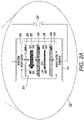
FIG. 2A is a diagram of an electrochemical liquid desiccant regeneration system according to an example embodiment; -
FIG. 3 is a schematic diagram of staged electrochemical liquid desiccant regeneration with staged dehumidification according to an example embodiment; -
FIG. 4 is a schematic diagram of the flows between an air contactor and a regeneration system as shown inFIG. 4 according to an example embodiment; -
FIG. 5 is a block diagram of thermal control of a staged electrochemical liquid desiccant regenerator coupled with a staged air contactor according to an example embodiment; -
FIGS. 6A-D are block diagrams of staged regenerated liquid desiccant dehumidification systems according to various example embodiments; and -
FIG. 7 is a flow chart of a method according to an example embodiment. - The present disclosure relates to regenerated liquid desiccant dehumidification systems, and in certain embodiments, electrochemically regenerated systems. A liquid desiccant system may be used in, among other things, heating, ventilation, and air-conditioning (HVAC). As set forth above, air conditioning is an energy intensive process and is responsible for nearly 10% of U.S. electricity consumption, with dehumidification accounting for more than half of the energy load in humid regions. The systems described herein provide an efficient, thermodynamic approach to dehumidification for air conditioning utilizing staged regeneration of the liquid desiccant.
- The systems each utilize two, or more, liquid desiccant streams having different salt concentrations supplied to one or more air contactors to produce a stream of dehumidified air. Instead of regenerating liquid desiccant to a single, higher, concentrated output stream that would provide the desired delivery conditions of the resulting, treated air stream, multiple streams (e.g., at least two) are supplied at lower and/or increasing concentrations up to that single stream concentration. For treated air going from a hot and humid condition to a cool and dry condition, the difference in water concentrations (i.e., relative humidity of the before and after air streams) may be as much as 100%. For example, to obtain a 90 °F and 90% relative humidity output air condition may only require a desiccant concentration of 15% of lithium chloride (LiCl) desiccant dissolved in water, but to obtain a delivery condition of 70 °F and 60% relative humidity may require a desiccant concentration of 30% LiCl or more. However, a significant amount of dehumidification can take place with a concentration of desiccant well below 30%.
- Using staged regeneration provides for reduced energy usage, reduced costs, and reduced system complications. Since regeneration energy is nonlinearly proportional to liquid desiccant concentration, if a portion of the liquid desiccant solution is not fully concentrated, the amount of energy used for regeneration is reduced. For electrochemical liquid desiccant regenerators, as described herein, concentrating to high concentrations (e.g., greater than 30%) increases operating costs. By staging concentration of the liquid desiccant at lower concentrations, operating costs (e.g., energy) as well as capital costs in terms of the size of the overall system and individual components (e.g., membranes) is reduced. For example, the desiccant concentration level is proportional to the size of an electrochemical regenerator membrane; however, electrochemical membranes are significantly more expensive than air contactor materials. Lower concentrations may use smaller, or fewer, membranes, or different types of membranes that tailored for the lower concentration. Further, to maintain desiccant capability in the air contactor, latent heat must be rejected. Using a staged air contactor provides multiple opportunities for external cooling of the liquid desiccant, which avoids inefficiencies associated with single point external cooling and complications associated with internal cooling in an air contactor.
- The staged regeneration of liquid desiccants described herein is applicable to a variety of liquid desiccant dehumidifying systems including thermally regenerated, electrochemically regenerated systems, and combinations thereof. For example, thermal regeneration systems involve one or more of a variety of evaporative processes, including regeneration by heating, by reduced pressure (e.g. membrane pervaporation), by azeotropic removal, etc. However, exemplary embodiments herein are described with respect to an electrochemical regeneration system that utilizes a redox-assisted electrodialysis process that enables a membrane-based liquid desiccant air conditioning system. In this redox-assisted electrodialysis (ED) process, an aqueous solution of a redox-active species is circulated between the anode and cathode of an electrochemical stack to concentrate ionic solutions, eliminating thermodynamic phase changes driven by the heat or pressure necessary for vapor compression (VC) or desiccant based air conditioning. Liquid desiccants (e.g., aqueous solutions of salts such as lithium chloride) will absorb moisture from air across a membrane interface. Diluted liquid desiccants will be efficiently re-concentrated, avoiding the latent heat input required to evaporate water. It is estimated that the enhanced efficiency of this cycle leads to 1.5 quads of energy savings yearly by 2030.
- In
FIG. 1 , a diagram illustrates adehumidification system 100 utilizing a liquiddesiccant regeneration system 110, here an electrochemical liquid desiccant regeneration system, in conjunction with anair contactor 120. The regeneration system outputs a single concentrated solution of liquid desiccant (e.g., an aqueous salt solution) to theair contactor 120. As used throughout this disclosure, an air contactor refers to a liquid to air mass and energy exchanger, which includes a membrane energy exchanger, and in certain embodiments is a dehumidifying air contactor. Air is flowed over the concentrated solution (e.g., having a concentration of up to 40%) of liquid desiccant either directly or via a membrane where water from the air stream is absorbed by the liquid desiccant stream. The air stream may be outside air, return air, or exhaust air from an enclosed space (e.g., building) that thesystem 100 is used to supply, or a combination of two or more of outside, exhaust, and return air. After absorbing the water from the air, the liquid desiccant stream is diluted and a single stream is output from theair contactor 120. The diluted liquid desiccant stream is then cycled back to theregeneration system 110 for regeneration (i.e., increased concentration of liquid desiccant). - In addition, a dehumidified air stream 104 (i.e., having a lower water content by percent mass than air stream 102) is output from the
air contactor 120. Aheat transfer system 130 can optionally be used to remove sensible heat from the air to supply aconditioned air stream 106 to the enclosed space (i.e., building). In other embodiments, sensible heat is removed earlier, or at other points, in the system for improved thermodynamic efficiencies. Sensible heat refers to the amount of energy needed to increase, or in this case decrease, the temperature of theair stream 104 independent of phase changes. Theheat transfer system 130 may include any type of known heat exchange system such as vapor compression, indirect evaporative cooling, chilled water or glycol, and/or heat pipes. Also, latent heat needs to be rejected from the system: from the liquid desiccant before or after the air contactor and/or from the input or output air streams. Latent heat can be as much as 80% of the total load for outdoor air, where 1 Ton is equivalent to 3.5 kW and 5 kg water per hour. - In systems with a single solution stream between the regeneration system and an air contactor, the concentrated liquid desiccant solution enters the air contactor at the highest needed concentration and leaves at some lower concentration of liquid desiccant. In these systems, a high flow rate of solution has a low liquid desiccant concentration change across the air contactor (e.g., a change of about 2%) and requires more energy to concentrate the solution. However, there may be less need for integration with heat rejection as latent heat can be removed externally such as from the input or output liquid desiccant stream for the air contactor. Alternatively, low flow rates of the solution provide an increased, or maximum, concentration change across the air contactor (e.g., a change of about 15%) and use less energy to concentrate the solution. However, additional temperature control for the air contactor may be needed such as with added flow paths of cooling fluid with high flow rates for internal cooling within the air contactor. These operating conditions can be varied as design choices and are better understood with a more detailed description of an electrochemical regeneration system.
-
FIG. 2 illustrates a diagram of an electrodialytic liquid desiccant air conditioning (ELDAC)system 200 as described above in accordance with certain embodiments. Thesystem 200 includes adesiccant section 202 and acooling section 204. In thedesiccant section 202, outdoor air 206 (and/or recirculated air) is forced across anair contactor 208 such as an air-liquid interface or liquid-carrying membrane dryer. In certain embodiments, theair 206 may be outside air of high temperature and high relative humidity (RH).Water 209 from theair 206 is absorbed at theair contactor 208 into a concentratedliquid desiccant 210, e.g., an aqueous salt solution, is then passed through a redox-assistedelectrochemical regenerator 212 to separate dilute stream 214 (e.g., discharge water) and re-concentrate thedesiccant stream 210. Example salts that may be used for the desiccant include, for example, LiCl, NaCl, LiBr, and CaCl2. - The humidity (i.e., water content by percent mass of the humid air) is reduced in the
air 215 leaving thedesiccant section 202, wherein it is cooled by thecooling section 204. Thiscooling section 204 may include anevaporator 216 and other components not shown (e.g., condenser, compressor). Because theair 215 entering thecooling section 204 has lower relative humidity compared to the outside/recirculatedair 206, theevaporator 216 is more efficient and can reduce the temperature of the cooledair 220 by a greater amount than if theevaporator 216 had to also condense moisture from theincoming air 215. Experimental results measuring the energy used by redox-assisted electrodialysis to concentrate ionic aqueous solutions show thatELDAC system 100 can have a regeneration specific heat input (RSHI) less than 0.05 kBTU/lb, which is up to 30 times lower than currently used thermal regeneration methods. - As seen in the
detail view 222 ofFIG. 2A , redox-assistedregenerator 212 has two outerion exchange membranes 224 that separate theouter redox channels 226 from theinner concentrate 210 and dilute 214 streams. In this example the outerion exchange membranes 224 are configured as anion exchange membranes (AEM). Theconcentrate 210 and dilute 214 streams are separated by a centralion exchange membrane 230, which in this example is a cation exchange membrane (CEM). In other configurations, the centralion exchange membrane 230 may be an AEM and theouter membranes 224 may be CEMs. An efficient membrane pair of one CEM and one AEM in the redox-assistedregenerator 212 has a Coulombic efficiency above 70%. - The four (or more) chambered desalination cell may use either one redox-active species that is circulated around the anode and cathode, where it undergoes faradaic reactions at both electrodes, or two redox-active species that are each confined to the anode or cathode respectively. An
external voltage 232 induces oxidation or reduction in redox-active shuttle molecules, driving ion movement across themembranes re-concentrated desiccant 210 anddischarge water 214. The percentages of salt concentrations shown inFIG. 2A are examples only - both inlets do not need to have the same concentration and the output concentrations may have a range of differences in concentrations. This goal can be achieved over multiple stages. One proposed redox shuttle is a positively charged ferrocene derivative such as (1,1'-bis(3-(trimethylammonio)propyl) ferrocene/1,1'-bis(3-(trimethylammonio)propyl) ferrocenium, [BTMAP-Fc]2+/[BTMAP-Fc]3+) 234, which is non-toxic, highly stable, has very rapid electrochemical kinetics and negligible membrane permeability. Other redox shuttle solutions may include ferrocyanide/ ferricyanide ([Fe(CN)6]4-/[Fe(CN)6]3-) or a negatively charged ferrocene derivative. The moving parts of the system may include low pressure pumps for liquid circulation and fans for air circulation. Additional details of this type of four-channel, electrodialytic, stack with redox shuttle assist can be found in commonly-ownedU.S. Patent No. 10,821,395 - As discussed above, latent heat must be rejected from the dehumidification system. Using external rejection, the liquid desiccant may be circulated with a higher flow rate and a less complicated and smaller air contactor design may be utilized since the heat removal system is external to the air contactor. However, there is a smaller gradient in the liquid desiccant concentration change due to lower osmotic losses. Alternatively, internal latent heat rejection may be used for systems circulating the liquid desiccant at a lower flow rate. The lower average concentration leads to fewer losses (e.g., due to electroosmotic drag, resistance, Coulombic efficiency), but the lower flow rate can also lead to less regeneration.
- In certain circumstances, an air contactor would utilize a low liquid desiccant flow rate with a modest temperature increase (e.g., five degrees) from input to output and a concentration decrease of about 15%. The air contactor would also include cooling fluid (e.g., water) with a temperature increase of about five degrees and a counter flow (counter to the flow of cooling fluid and liquid desiccant) of air having a decrease in temperature of about 10 °C and a decrease in relative humidity (e.g., from 80% to 50%). However, to achieve these delivery conditions (e.g., temperature and relative humidity decreases), the air contactor would produce about a 15% concentration gradient (e.g., concentration changing from
input 30% to diluted output of 15%), which would require the liquid desiccant regenerator to reconcentrate the liquid desiccant back up to a 30% salt concentration. This is challenging for the regenerator membranes and difficult due to osmotic drag, and in certain circumstances, impossible due to electroosmotic drag. When regeneration takes place at the highest concentration for desired delivery conditions, the flow rate must also be higher since less water is absorbed. - Instead of regenerating the liquid desiccant to the highest concentration necessary for a system's most stringent delivery conditions, staged regeneration and dehumidification utilizes lower concentrations of smaller volumes of solution in incremental stages to ramp up to the final concentration. Embodiments described herein utilize an electrochemical regenerator, as described above in connection with
Figs. 2 and2A unless otherwise described, to produce two or more concentrated liquid desiccant output solutions in connection with two, or more, air contactor stages. However, the embodiments may be used with other liquid desiccant regeneration systems such as thermal regeneration and reverse osmosis systems. Unlike the systems described above, which utilize a single regenerator concentrated output stream, regeneration and dehumidification occur in stages using two or more streams of liquid desiccant having a smaller concentration than that of a system using a single regenerator concentrated output stream. Various systems utilizing staged liquid desiccant regeneration in combination with two or more air contactor stages are further described below. -
FIG. 3 illustrates asystem 300 including a stagedregenerator 310 coupled with a staged air contactor 320. While the stagedregenerator 310 is described as an electrochemical regenerator, the stages may be similarly utilized in a reverse osmosis driven regenerator or in a thermal regeneration system. Each stage of theregenerator 310A-D outputs a concentrated stream ofliquid desiccant 312A-D and each stage of theair contactor 320A-D returns a diluted stream ofliquid desiccant 314A-D. The stages of both theregenerator 310A-D andair contactor 320A-D are demarcated by dashed lines. Although the stages are shown as being aligned with each other, this is not required, and the respective stages within a component (i.e., regenerator, air contactor) may have varying sizes. As can be seen, theconcentrated streams 312A-D are output from the concentrated liquid desiccant chamber of theregenerator 310, and the diluted streams 314A-D are returned to the diluted desiccant chamber which is separated from the concentrated desiccant by an interface, or membrane. - An overview of an example embodiment of the stages A-D may be understood from
FIG. 3 . However, the concentrations used herein are merely exemplary and embodiments of the described systems may be designed using any range of concentrations where at least one of the staged concentrated outputs is less than the highest concentration for the designed air delivery conditions. UsingFig. 3 , the highest concentration for the designed delivery conditions is 30% salt concentration, as shown inconcentrated output stream 312D. Thus, a first stage of theregenerator 310A outputs a first concentrated liquid desiccant stream having a lower concentration of 17% to a firstair contactor stage 320A. The firstair contactor stage 320A returns a firstdiluted output stream 314A having a concentration of 15% to the first stage of theregenerator 310A. A subsequent stage outputs a second concentratedliquid desiccant stream 312B having a concentration higher than that ofoutput stream 312A, e.g., 20%, to a subsequentair contactor stage 320B. Theair contactor stage 320B returns a seconddiluted output stream 314B having a concentration of 17%, which is higher than that ofoutput stream 314A, to the subsequent stage of theregenerator 310B. - A third stage outputs a third concentrated
liquid desiccant stream 312C having a concentration higher than that ofoutput stream 312B, e.g., 25%, to a third air contactor stage 320C. The air contactor stage 320C returns a thirddiluted output stream 314C having a concentration of 22%, which is higher than that ofoutput stream 314B, to the third stage of theregenerator 310C. Next, a fourth, and here final, stage outputs a fourth concentratedliquid desiccant stream 312D having a concentration higher than that ofoutput stream 312C, e.g. 30%, to a fourthair contactor stage 320D. Theair contactor stage 320D returns a finaldiluted output stream 314D having a concentration of 27%, which is higher than that ofoutput stream 314C, to the fourth stage of theregenerator 310D. While it is shown that the diluted output streams 314A-D are returned to specific stages, or areas, of theregenerator 310, they may be recirculated, or split, to any portion of the dilute liquid desiccant chamber of theregenerator 310. - As explained above, the regenerator chambers have the concentrated liquid desiccant and diluted desiccant streams flowing in opposing directions through the
regenerator 310. For example, the concentrated desiccant flows in the direction ofarrow 316 toward increasing concentrations, and the diluted solution flows in the direction ofarrow 318 toward increasingly diluted concentrations. Thus, theregenerator 310 provides desiccant at lower concentrations than the final output concentration at incremental stages along flow path of the concentrating desiccant. WhileFIG. 3 illustrates four stages, the systems described herein can have any number of stages that utilize at least two concentrated desiccant output streams of differing concentrations. - The dehumidifying air contactor is also shown in
stages 320A-D. Input air may flow along the stages of the air contactor in the direction of arrow 322 to increasingly expose the air stream to higher concentrations of liquid desiccant and increasingly remove water from the air stream. In alternative embodiments, air may be introduced at different stages of the air contactor to provide varying levels of dehumidification. In certain embodiments, the air streams exposed to the different air contactor stages 320A-D are combined to output an air stream at designed delivery conditions. - The staged system also allows for improved latent heat removal. The staged concentration liquid desiccant output streams 312A-D provide an opportunity to remove heat at multiple input locations to the air contactor 320, which further reduces energy required for latent heat removal. The heat removal system represented by
arrow 330 utilizes cooling fluid, such as water, that cools the liquid desiccant at two or more inputs to the air contactor 320. The heat removal system may utilize direct or indirect heat removal such as one or more of evaporative cooling, dry cooling, and vapor compression. In alternative embodiments, theheat removal system 330 may be integrated into the air contactor 320, for example, at one or more stages in addition, or as an alternative to, an external cooling system. - The flows of the various concentrate and diluted liquid desiccant streams are shown in more detail in
FIG. 4 . In this embodiment three stages are shown, but as set forth above any number of stages may be utilized and the concentrations are merely provided as examples. As above, afirst regenerator stage 410A outputs a concentrated liquid desiccant stream having a concentration of 20% where a first portion of the stream 412AA is input to a firstair contactor stage 420A and a second portion of the stream 412AB is input for further concentration to asecond regenerator stage 410B. The firstair contactor stage 420A outputs a diluted liquid desiccant stream having a concentration of 15% where a portion of the stream 414AA is recirculated to the concentrated feed of thefirst regenerator stage 410A to be further concentrated and a second portion of the stream 414AB is recirculated to the diluted feed of thefirst regenerator stage 410A. - The
second regenerator stage 410B outputs a concentrated liquid desiccant stream having a concentration of 25%, or higher than the output concentrated stream of the first stage, where a first portion of the stream 412BA is input to a secondair contactor stage 420B and a second portion of the stream 412BB is input for further concentration to a subsequent, or third,regenerator stage 410C. The secondair contactor stage 420B outputs a diluted liquid desiccant stream having a concentration of 20% where a portion of the stream 414BA is recirculated to the concentrated feed of thesecond regenerator stage 410B to be further concentrated and a second portion of the stream 414BB is recirculated to the diluted feed of thesecond regenerator stage 410B. Thesecond regenerator stage 410B also outputs adiluted stream 416B having a concentration of 15% to thefirst regenerator stage 410A for further dilution. While the output concentration of the second air contactor stage 414BA, BB is shown as the same concentration as the input stream 412AB concentration to thesecond regenerator stage 410B, this is not required; they may be different. - The
third regenerator stage 410C outputs a concentrated liquid desiccant stream having a concentration of 30%, or higher than the output concentrated stream of the second stage and if the final stage of the system, substantially equal to the highest concentration required for the designed delivery conditions. Thestream 412C is input to a thirdair contactor stage 420C. The thirdair contactor stage 420C outputs a diluted liquid desiccant stream having a concentration of 25% where a portion of the stream 414CA is recirculated to the concentrated feed of thethird regenerator stage 410C to be further concentrated and a second portion of the stream 414CB is recirculated to the diluted feed of thethird regenerator stage 410C. Thethird regenerator stage 410C also outputs adiluted stream 416C having a concentration of 20% to thesecond regenerator stage 410B for further dilution. Again, the output concentration of the second air contactor stage 414BA, BB is not necessarily the same concentration as the input stream 412AB concentration to thesecond regenerator stage 410B. - The
first contactor stage 410A is shown as outputting adiluted stream 416A having a zero (or substantially zero) percent concentration of liquid desiccant, which may be expelled from the system. However, in certain embodiments, dilutedstream 416A may have a higher concentration of liquid desiccant, though less than the concentration of the diluted streams 414AA, 414AB, and 416B input to thefirst stage 410A, and this stream may be further regenerated (i.e., concentrated) by inputting 416A to a second, different air contactor, which is a humidifying air contactor. Similar to the air contactor stages 420A-C, the second air contactor may be a liquid to air mass and energy exchanger, including a membrane energy exchanger. - At the second air contactor, air is flowed over
stream 416A, either directly or via a membrane, where water fromstream 416A is absorbed by the air stream. The air stream may be outside, ambient air from the environment, or exhaust air. The resulting humidified air is output from the second air contactor as an output, humidified air stream that is returned to the environment external to the components of the dehumidification system. The resulting concentrated liquid desiccant stream is then recirculated to one or more of the regenerator stages 410A-C for further use in the regeneration process. The second air contactor liquid desiccant output stream has a concentration of liquid desiccant higher than that ofstream 416A, and in certain embodiments, the second air contactor output stream has a concentration in a range of about 2-35 %. - The various flows shown in
FIG. 4 may occur simultaneously, or the timing of various stages of the system may also be individually controlled. For example, one or more regenerator stages 410A-C and/or one or more air contactor stages 420A-C may be operated simultaneously, or in various combinations. The system may include storage containers, with or without bypass valves, at various positions throughout the system to store/contain diluted and/or regenerated solutions of liquid desiccant to take advantage of energy savings (e.g,, to operate energy intensive portions of the system during off-peak or less expensive times). -
FIG. 5 illustrates an example system with a stagedliquid desiccant regenerator 510 coupled with a stagedair contactor 520 along with sensible and latent heat removal. As discussed above, the regenerator stages 510B-D couple with respective air contactor stages 520B-D to provide liquid desiccant streams of different concentrations. For example,regenerator stage 510D outputs astream 512D having a concentration of 30% toair contactor stage 520D, which outputs a dilutedstream 514D having a salt concentration of 25%, which is recirculated to an input of at least one stage of theregenerator 510, e.g.,stage 510D.Regenerator stage 510C outputs astream 512C having a concentration of 25% to air contactor stage 520C, which outputs adiluted stream 514C having a salt concentration of 20%, which is recirculated to an input of at least one stage of theregenerator 510, e.g.,stage 510C. -
Regenerator stage 510B outputs astream 512B having a concentration of 20% toair contactor stage 520B, which outputs a diluted stream having a salt concentration of 15%, which is recirculated to an input of at least one stage of theregenerator 510. In the embodiment shown, the diluted output stream is split into a first stream 514BA that is recirculated as input toregenerator stage 510B and into a second stream 514BB that is recirculated as input toregenerator stage 510A. Similarly, outputs from any of the air contactor stages 520B-D can be input to theregenerator 510 at any one stage, or split amongst two ormore stages 510A-D. Theair contactor 520 is staged to precisely control the liquid desiccant concentrations at each stage. - In certain embodiments, the regenerator and the air contactor do not have an equal number of stages. For example, some of the stages are coupled to the air contactor (e.g., stages 510B-D) and some of the stages internally regenerate the liquid desiccant (e.g.,
stage 510A). In further embodiments, one or more regenerator stages may be coupled to a second, humidifying air contactor as described above. For example,output stream 516 may couple to another air contactor or alternatively be used as a drain for the system. - Liquid desiccant within
air contactor 520 will also heat up as moisture is transferred from the air to the liquid desiccant. As the liquid desiccant and air increase in temperature, the capability of the liquid desiccant to absorb moisture from air is diminished. Thus, maintaining a lower temperature in the air contactor improves operability and efficiency of the air contactor. This can be achieved in several ways including pre-cooling the air entering the air contactor, pre-cooling the liquid desiccant, and/or introducing a third cooling fluid inside the air contactor. - The embodiment of
FIG. 5 shows the evaporative side of a vapor compression system in thermal contact with each stage of liquid desiccant before enteringair contactor 520, which reduces, or minimizes, the complication of theair contactor 520 design while providing staged cooling. While the staged cooling is illustrated as a vapor compression system, cooling may be accomplished through alternative methods such as with chilled water or indirect evaporative cooling. As shown, each concentration feed of desiccant may be separately cooled to control the input temperature of each concentration of desiccant at each stage of theair contactor 520. For example,input desiccant 512B is cooled at 534B,input desiccant 512C is cooled at 534C, andinput desiccant 512D is cooled at 534D. In alternative embodiments, one or more cooling stations may cool one or more of the input desiccant streams 512B-D. Cooling station 534A also cools the liquid desiccant stream 514BB that is recirculated to theregenerator 510. - In addition to pre-cooling the liquid desiccant,
FIG. 5 shows an embodiment where theincoming air 502 to theair contactor 520 is also pre-cooled. Theincoming air 502 is exposed to anevaporator 536, which is coupled to thecooling stations 534A-D. After removal of sensible heat by exposure to theevaporator 536, the cooledincoming air 502A is exposed to one ormore stages 520B-D of theair contactor 520 and leaves asconditioned air stream 504. Theconditioned air stream 504 is then provided to the intended enclosed space (e.g., building). - Cooling fluid (e.g., gas or liquid) leaves the
evaporator 536 to enter avapor compressor 530 where the temperature of the cooling fluid is increased. The fluid is then provided to acondenser 532 that receives outside or vent/exhaust air 506 to expel heatedoutside air 508. Thecondenser 532 may be another air contactor as described above. The cooling fluid is then coupled to the liquiddesiccant cooling stations 534A-D, where such coupling includes an expansion valve. In certain embodiments, the vapor compression system may be used in connection with internal cooling, e.g., added cooled fluid flows, in one or more stages of theair contactor 520. -
FIGS. 6A-D illustrate various configurations of the staged regenerator and staged air contactor systems described above.FIG. 6A illustrates a singleregenerator having stages 610A-C coupled withmultiple air contactors air contactors FIG. 6B illustrates a singleregenerator having stages 610A-C coupled with a single air contactor havingmultiple stages 620A-C. As set forth above, regenerator stages 610A-C may be included in a single housing and air contactor stages 620A-C may be included in a single housing.FIG. 6C illustratesmultiple regenerators multiple stages 620A-C. For example, one or more ofregenerators FIG. 6D illustratesmultiple regenerators multiple air contactors regenerators air contactors - While embodiments described herein can involve a variety of configurations, staged liquid desiccant regeneration and dehumidification involves utilizing at least two concentrated liquid desiccant streams having different salt concentrations to dehumidify air using at least one salt concentration that is lower than a concentration required for an otherwise identical non-staged dehumidification system using a single salt concentration as set forth in
FIG. 7 . In certain embodiments liquid desiccant at a first concentration is received from a regenerator by an air contactor. The air contactor outputs air having a water content by percent mass that is lower than that of an incoming air stream to the air contactor and outputs a diluted liquid desiccant stream having a concentration lower than the input stream to theregenerator 702. This may be performed by a first stage of the air contactor. Liquid desiccant at a second concentration, higher than the first concentration is also received by the air contactor. The air contactor outputs air having a water content by percent mass that is lower than that of an incoming air stream to the air contactor and outputs a diluted liquid desiccant stream having a concentration lower than the second concentration to theregenerator 704. This may be performed by a second stage of the air contactor. For example, the air output from the second stage has a water content lower than water content of the air output from the first stage of the air contactor. In certain embodiments, the regenerator is a staged electrochemical liquid desiccant regenerator. - The systems described herein with respect to various embodiments involve a liquid desiccant regeneration system having staged outputs of at least two different desiccant concentrations in combination with a staged air contactor. These systems reduce energy consumption, particularly in electrochemically regenerated dehumidification and air conditioning systems, reduce system costs, increase the options for system operating ranges, and can reduce or eliminate the loss of desiccant materials in the system. They provide increased efficiency and environmentally responsible options for meeting the expected, increased need for dehumidification and air conditioning systems.
- Unless otherwise indicated, all numbers expressing feature sizes, amounts, and physical properties used in the specification and claims are to be understood as being modified in all instances by the term "about." Accordingly, unless indicated to the contrary, the numerical parameters set forth in the foregoing specification and attached claims are approximations that can vary depending upon the desired properties sought to be obtained by those skilled in the art utilizing the teachings disclosed herein. The use of numerical ranges by endpoints includes all numbers within that range (e.g. 1 to 5 includes 1, 1.5, 2, 2.75, 3, 3.80, 4, and 5) and any range within that range. Also, all uses of "%" with respect to concentrations in the application refer to weight percent (wt. %) unless otherwise indicated.
- The foregoing description has been presented for the purposes of illustration and description. It is not intended to be exhaustive or to limit the embodiments to the precise form disclosed. Many modifications and variations are possible in light of the above teachings. Any or all features of the disclosed embodiments can be applied individually or in any combination and are not meant to be limiting, but purely illustrative. It is intended that the scope of the invention be limited not with this detailed description, but rather, determined by the claims appended hereto.
Claims (15)
- A system, comprising:a liquid desiccant regeneration system comprising a first stage with a first concentrated output stream having a first concentration of liquid desiccant and a first diluted output stream and a second stage with a second concentrated output stream having a second concentration of liquid desiccant different than the first concentration and a second diluted output stream;a first air contactor stage coupled to the first concentrated output stream disposing a first input air stream having a first water content by percent mass in fluid communication with the first concentrated output stream to form a first output air stream having a second water content by percent mass lower than the first water content and a first diluted air contactor output stream, wherein the first diluted air contactor output stream is circulated back into the liquid desiccant regeneration system; anda second air contactor stage coupled to the second concentrated output stream disposing a second input air stream having a third water content by percent mass in fluid communication with the second concentrated output stream to form a second output air stream having a fourth water content by percent mass lower than the third water content and a second diluted air contactor output stream, wherein the second diluted air contactor output stream is circulated back into the liquid desiccant regeneration system and the first and second output air streams are combined.
- The system of claim 1, wherein the liquid desiccant regeneration system is an electrochemical regeneration system driven by an electric potential, optionally wherein the electrochemical regeneration system engenders faradaic reactions happening at two different electrodes and material undergoing the faradaic reactions is circulated from one electrode to the other and back again.
- The system of any preceding claim, wherein the liquid desiccant regeneration system is driven by reverse osmosis; and/or the liquid desiccant regeneration system is a thermal regeneration system.
- The system of any preceding claim, wherein the third water content by percent mass is different from the first water content by percent mass.
- The system of any preceding claim, further comprising a heat removal system coupled to at least two streams of a group comprising the first input air stream, the second input air stream, the first concentrated output stream, and the second concentrated output stream; optionally wherein the heat removal system is coupled to the at least two streams within at least one of the first and second air contactor stages.
- The system of claim 5, wherein the heat removal system comprises a first stage coupled to a first regenerated output stream and a second stage coupled to a second regenerated output stream.
- The system of claim 5 or claim 6, wherein the heat removal system comprises at least one of evaporative cooling, dry cooling and vapor compression.
- The system of any preceding claim, wherein the liquid desiccant regeneration system comprises a third stage coupled to one of the first and second stages.
- The system of any preceding claim, wherein at least one of the first and second diluted output streams is coupled to a third air contactor stage configured to produce a concentrated air contactor output stream having an increased salt concentration as compared to at least one of the first and second diluted output streams and to increase the water content by mass of a third input air stream, wherein the concentrated air contactor output stream is circulated back into the liquid desiccant regeneration system.
- An air contactor, comprising:a first input stream of liquid desiccant having a first concentration of desiccant;a second input stream of liquid desiccant having a second concentration of desiccant where the second concentration is higher than the first concentration; andan input air stream disposed in fluid communication with the first input stream of liquid desiccant and with the second input stream of liquid desiccant to produce a diluted output stream of liquid desiccant and an output air stream having a water content by mass lower than that of the input air stream.
- The air contactor of claim 10, wherein the input air stream is exposed to at least one of the first and second input streams of liquid desiccant through an intervening interface.
- The air contactor of claim 10 or claim 11, wherein the diluted output stream is coupled to a liquid desiccant regeneration system configured to provide the first and second input streams of liquid desiccant.
- The air contactor of any of claims 10 to 12, further comprising a heat removal system coupled to the first and second input streams.
- A system, comprising:a first liquid desiccant regeneration system configured to produce a first concentrated output stream having a first concentration of liquid desiccant;a second liquid desiccant regeneration system coupled to the first concentrated output stream and configured to produce a second concentrated output stream having a second concentration of liquid desiccant different than the first concentration;a first air contactor stage coupled to the first concentrated output stream disposing a first input air stream having a first water content by mass in fluid communication with the first concentrated output stream to form a first output air stream having a second water content by mass lower than the first water content and a first diluted output stream, wherein the first diluted output stream is circulated back into the first liquid desiccant regeneration system; anda second air contactor stage coupled to the second concentrated output stream disposing a second input air stream having a third water content by mass in fluid communication with the second concentrated output stream to form a second output air stream having a fourth water content by mass lower than the third water content and a second diluted output stream, wherein the second diluted output stream is circulated back into the second liquid desiccant regeneration system and the first and second output air streams are combined.
- The system of any one of claims 1 to 9 or 14, wherein the first air contactor stage and the second air contactor stage are separate air contactors, or are stages of the same air contactor.
Applications Claiming Priority (1)
| Application Number | Priority Date | Filing Date | Title |
|---|---|---|---|
| US17/204,703 US12085293B2 (en) | 2021-03-17 | 2021-03-17 | Staged regenerated liquid desiccant dehumidification systems |
Publications (1)
| Publication Number | Publication Date |
|---|---|
| EP4063001A1 true EP4063001A1 (en) | 2022-09-28 |
Family
ID=80447022
Family Applications (1)
| Application Number | Title | Priority Date | Filing Date |
|---|---|---|---|
| EP22157897.4A Pending EP4063001A1 (en) | 2021-03-17 | 2022-02-22 | Staged regenerated liquid desiccant dehumidification systems |
Country Status (5)
| Country | Link |
|---|---|
| US (2) | US12085293B2 (en) |
| EP (1) | EP4063001A1 (en) |
| JP (1) | JP2022145535A (en) |
| KR (1) | KR20220130009A (en) |
| CN (1) | CN115111672A (en) |
Cited By (5)
| Publication number | Priority date | Publication date | Assignee | Title |
|---|---|---|---|---|
| WO2024129618A1 (en) * | 2022-12-12 | 2024-06-20 | Mojave Energy Systems, Inc. | Liquid desiccant air conditioning system and control methods |
| US12276436B2 (en) | 2023-04-07 | 2025-04-15 | Mojave Energy Systems, Inc. | Ultra low flow desiccant air conditioning systems devices and methods |
| US12510257B2 (en) | 2021-12-22 | 2025-12-30 | Mojave Energy Systems, Inc. | Electrochemically regenerated liquid desiccant dehumidification system using a secondary heat pump |
| US12571546B2 (en) | 2022-04-13 | 2026-03-10 | Mojave Energy Systems, Inc. | Liquid desiccant air conditioning using air as heat transfer medium |
| US12693037B2 (en) | 2021-03-17 | 2026-07-28 | Mojave Energy Systems, Inc. | Staged regenerated liquid desiccant dehumidification systems |
Families Citing this family (5)
| Publication number | Priority date | Publication date | Assignee | Title |
|---|---|---|---|---|
| US11117090B2 (en) | 2018-11-26 | 2021-09-14 | Palo Alto Research Center Incorporated | Electrodialytic liquid desiccant dehumidifying system |
| US20220243932A1 (en) * | 2021-01-29 | 2022-08-04 | Palo Alto Research Center Incorporated | Electrochemical dehumidifier with multiple air contactors |
| US11944934B2 (en) * | 2021-12-22 | 2024-04-02 | Mojave Energy Systems, Inc. | Electrochemically regenerated liquid desiccant dehumidification system using a secondary heat pump |
| WO2023150774A2 (en) * | 2022-02-07 | 2023-08-10 | Energetico, Inc. | Compressorless air conditioning system |
| WO2026085217A1 (en) * | 2024-10-15 | 2026-04-23 | Massachusetts Institute Of Technology | Multistage absorption and desorption for co2 separations |
Citations (4)
| Publication number | Priority date | Publication date | Assignee | Title |
|---|---|---|---|---|
| US3277954A (en) * | 1966-03-04 | 1966-10-11 | Lithonia Lighting Inc | System for producing conditioned air |
| US20150292754A1 (en) * | 2014-04-15 | 2015-10-15 | Andrew Mongar | Air conditioning method using a staged process using a liquid desiccant |
| US20200164312A1 (en) * | 2018-11-26 | 2020-05-28 | Palo Alto Research Center Incorporated | Electrodialytic system used to remove solvent from fluid and non-fluid flows |
| US10821395B2 (en) | 2018-02-07 | 2020-11-03 | Palo Alto Research Center Incorporated | Electrochemical desalination system |
Family Cites Families (219)
| Publication number | Priority date | Publication date | Assignee | Title |
|---|---|---|---|---|
| US2214880A (en) | 1933-01-25 | 1940-09-17 | Robert B P Crawford | Regenerative cooling system |
| US2147248A (en) | 1934-12-26 | 1939-02-14 | Walter L Fleisher | Adsorption system of air conditioning |
| US2290465A (en) | 1939-04-20 | 1942-07-21 | Robert B P Crawford | Air conditioning system |
| US2276970A (en) | 1940-04-23 | 1942-03-17 | Hibberd Frederick Hyde | Air conditioning system |
| US2672024A (en) | 1951-01-12 | 1954-03-16 | Carrier Corp | Air conditioning system employing a hygroscopic medium |
| US2798570A (en) | 1956-02-20 | 1957-07-09 | Surface Combustion Corp | Air conditioning |
| US3336423A (en) | 1964-12-31 | 1967-08-15 | Exxon Research Engineering Co | Method of forming a catalytic electrode |
| US3350892A (en) | 1966-04-04 | 1967-11-07 | Midland Ross Corp | Two-stage air conditioning system |
| US3819118A (en) | 1970-09-09 | 1974-06-25 | A Brock | Drip irrigation |
| US3729142A (en) | 1970-12-03 | 1973-04-24 | Diaz J Leal | Drippers for irrigation |
| JPS5213667B2 (en) | 1972-07-18 | 1977-04-15 | ||
| US3981452A (en) | 1975-02-10 | 1976-09-21 | Gershon Eckstein | Irrigation pipes with dripper units and method of its manufacture |
| US3993248A (en) | 1975-08-13 | 1976-11-23 | Harmony Emitter Company, Inc. | Fluid flow regulator |
| US4118299A (en) | 1977-07-14 | 1978-10-03 | Henri Jean Robert Maget | Electrochemical water desalination process |
| US4164125A (en) | 1977-10-17 | 1979-08-14 | Midland-Ross Corporation | Solar energy assisted air-conditioning apparatus and method |
| US4180985A (en) | 1977-12-01 | 1980-01-01 | Northrup, Incorporated | Air conditioning system with regeneratable desiccant bed |
| US4340480A (en) | 1978-05-15 | 1982-07-20 | Pall Corporation | Process for preparing liquophilic polyamide membrane filter media and product |
| NO153836C (en) | 1978-05-15 | 1986-06-04 | Pall Corp | HYDROFILE, ALCOHOLUALLY SOLUBLE POLYAMIDE MEMBRANES AND PROCEDURES FOR THEIR PREPARATION. |
| US4205529A (en) | 1978-12-04 | 1980-06-03 | The United States Of America As Represented By The United States Department Of Energy | LiCl Dehumidifier LiBr absorption chiller hybrid air conditioning system with energy recovery |
| US4259849A (en) | 1979-02-15 | 1981-04-07 | Midland-Ross Corporation | Chemical dehumidification system which utilizes a refrigeration unit for supplying energy to the system |
| US4287721A (en) | 1979-06-11 | 1981-09-08 | Robison Harry I | Chemical heat pump and method |
| US4355683A (en) | 1981-05-11 | 1982-10-26 | Midland-Ross Corporation | System of moisture and temperature conditioning air using a solar pond |
| US4612019A (en) | 1982-07-22 | 1986-09-16 | The Dow Chemical Company | Method and device for separating water vapor from air |
| US4593534A (en) | 1985-02-21 | 1986-06-10 | Analytic Power Corporation | Electrochemically driven heat pump |
| US4700550A (en) | 1986-03-10 | 1987-10-20 | Rhodes Barry V | Enthalpic heat pump desiccant air conditioning system |
| US4691530A (en) | 1986-09-05 | 1987-09-08 | Milton Meckler | Cogeneration and central regeneration multi-contactor air conditioning system |
| SE459716B (en) * | 1987-11-20 | 1989-07-31 | Lars Gunnar Hellman | PROCEDURES FOR CONDITIONING OF HUMID GAS |
| US4900448A (en) | 1988-03-29 | 1990-02-13 | Honeywell Inc. | Membrane dehumidification |
| US4905479A (en) | 1989-01-27 | 1990-03-06 | Gas Research Institute | Hybrid air conditioning system |
| US4955205A (en) | 1989-01-27 | 1990-09-11 | Gas Research Institute | Method of conditioning building air |
| US4941324A (en) | 1989-09-12 | 1990-07-17 | Peterson John L | Hybrid vapor-compression/liquid desiccant air conditioner |
| US4984434A (en) | 1989-09-12 | 1991-01-15 | Peterson John L | Hybrid vapor-compression/liquid desiccant air conditioner |
| US5058394A (en) | 1990-02-06 | 1991-10-22 | Battelle Memorial Institute | Hybrid air conditioning system subsystem integration |
| US5070703A (en) | 1990-02-06 | 1991-12-10 | Battelle Memorial Institute | Hybrid air conditioning system integration |
| US5022241A (en) | 1990-05-04 | 1991-06-11 | Gas Research Institute | Residential hybrid air conditioning system |
| JPH0418919A (en) | 1990-05-14 | 1992-01-23 | Babcock Hitachi Kk | Method and device for electrodialysis |
| JPH05245346A (en) | 1991-03-19 | 1993-09-24 | Babcock Hitachi Kk | Electrodialyzer |
| WO1995028609A1 (en) | 1992-08-24 | 1995-10-26 | Milton Meckler | Desiccant assisted multi-use air pre-conditioner unit with system heat recovery capability |
| US5351497A (en) | 1992-12-17 | 1994-10-04 | Gas Research Institute | Low-flow internally-cooled liquid-desiccant absorber |
| US5460004A (en) | 1993-04-09 | 1995-10-24 | Ari-Tec Marketing, Inc. | Desiccant cooling system with evaporative cooling |
| JP3184015B2 (en) | 1993-08-10 | 2001-07-09 | 野村マイクロ・サイエンス株式会社 | Ultrapure water production equipment |
| IL108171A (en) | 1993-12-24 | 2000-01-31 | Hydromatic Ltd | Flow reducer devices and drip irrigation emitter including same |
| US5528905A (en) | 1994-03-25 | 1996-06-25 | Essex Invention S.A. | Contactor, particularly a vapour exchanger for the control of the air hygrometric content, and a device for air handling |
| AUPM592694A0 (en) | 1994-05-30 | 1994-06-23 | F F Seeley Nominees Pty Ltd | Vacuum dewatering of desiccant brines |
| US5634269A (en) | 1994-09-09 | 1997-06-03 | Gas Research Institute | Thin plastic-film heat exchanger for absorption chillers |
| JPH08189666A (en) | 1994-12-28 | 1996-07-23 | Daikin Ind Ltd | Air conditioner |
| US5615838A (en) | 1995-03-10 | 1997-04-01 | Drip Irrigation Systems, Ltd. | In-line retention drip emitter |
| USRE39288E1 (en) | 1995-04-20 | 2006-09-19 | Gad Assaf | Heat pump system and method for air-conditioning |
| US5791157A (en) | 1996-01-16 | 1998-08-11 | Ebara Corporation | Heat pump device and desiccant assisted air conditioning system |
| ES2108654B1 (en) | 1996-05-07 | 1998-07-01 | Univ Alicante | PROCEDURE FOR THE ELECTROCHEMICAL SYNTHESIS OF N-ACETILCISTEINA FROM CISTINA. |
| US5928409A (en) | 1997-11-12 | 1999-07-27 | New Jersey Institute Of Technology | Method and apparatus for gas removal by cyclic flow swing membrane permeation |
| EP1029201A1 (en) | 1997-11-16 | 2000-08-23 | Drykor Ltd. | Dehumidifier system |
| IL141579A0 (en) | 2001-02-21 | 2002-03-10 | Drykor Ltd | Dehumidifier/air-conditioning system |
| US6080507A (en) | 1998-04-13 | 2000-06-27 | Celgard Inc. | Trilayer battery separator |
| US6149817A (en) | 1999-03-08 | 2000-11-21 | Celgard Inc. | Shell-less hollow fiber membrane fluid contactor |
| JP2001174074A (en) | 1999-12-21 | 2001-06-29 | Ebara Corp | Dehumidifier |
| IL134196A (en) | 2000-01-24 | 2003-06-24 | Agam Energy Systems Ltd | System for dehumidification of air in an enclosure |
| US6568466B2 (en) | 2000-06-23 | 2003-05-27 | Andrew Lowenstein | Heat exchange assembly |
| US6497107B2 (en) | 2000-07-27 | 2002-12-24 | Idalex Technologies, Inc. | Method and apparatus of indirect-evaporation cooling |
| US6711907B2 (en) | 2001-02-28 | 2004-03-30 | Munters Corporation | Desiccant refrigerant dehumidifier systems |
| US6497749B2 (en) | 2001-03-30 | 2002-12-24 | United Technologies Corporation | Dehumidification process and apparatus using collodion membrane |
| IL144119A (en) | 2001-07-03 | 2006-07-05 | Gad Assaf | Air conditioning system |
| US6719891B2 (en) | 2001-11-21 | 2004-04-13 | Ecolab Inc. | Point-of-use generation of chlorinated alkaline cleaning solutions by electrolysis |
| AU2003268052A1 (en) | 2002-08-02 | 2004-02-23 | University Of South Carolina | Production of purified water and high value chemicals from salt water |
| IL152885A0 (en) | 2002-11-17 | 2003-06-24 | Agam Energy Systems Ltd | Air conditioning systems and methods |
| US6837056B2 (en) | 2002-12-19 | 2005-01-04 | General Electric Company | Turbine inlet air-cooling system and method |
| DE10261275A1 (en) | 2002-12-27 | 2004-07-15 | EISENMANN Maschinenbau KG (Komplementär: Eisenmann-Stiftung) | Electrodialysis device |
| US7306650B2 (en) | 2003-02-28 | 2007-12-11 | Midwest Research Institute | Using liquid desiccant as a regenerable filter for capturing and deactivating contaminants |
| US6986428B2 (en) | 2003-05-14 | 2006-01-17 | 3M Innovative Properties Company | Fluid separation membrane module |
| JP4885725B2 (en) | 2003-10-27 | 2012-02-29 | ジーイー・アイオニクス・インコーポレイテッド | Improved electrodialysis system and process |
| US7279215B2 (en) | 2003-12-03 | 2007-10-09 | 3M Innovative Properties Company | Membrane modules and integrated membrane cassettes |
| US7306654B2 (en) | 2004-01-30 | 2007-12-11 | Ronald King | Method and apparatus for recovering water from atmospheric air |
| US7452920B2 (en) | 2004-09-17 | 2008-11-18 | Uchicago Argonne, Llc | Electronically and ionically conductive porous material and method for manufacture of resin wafers therefrom |
| US20060141346A1 (en) | 2004-11-23 | 2006-06-29 | Gordon John H | Solid electrolyte thermoelectrochemical system |
| JP4500243B2 (en) | 2005-09-28 | 2010-07-14 | 東芝キヤリア株式会社 | Dehumidification system |
| WO2007066212A2 (en) | 2005-12-07 | 2007-06-14 | Adir Segal, Ltd. | System and method for managing water content in a fluid |
| CN101394917B (en) | 2006-03-02 | 2012-03-07 | 真锅征一 | Pore Diffusion Flat Membrane Separation Device |
| GB0614338D0 (en) | 2006-07-19 | 2006-08-30 | Acal Energy Ltd | Fuel cells |
| TWI404897B (en) * | 2006-08-25 | 2013-08-11 | Ducool Ltd | System and method for managing water content in a fluid |
| EP2109495A4 (en) | 2007-01-20 | 2011-09-28 | Dais Analytic Corp | Multi-phase selective mass transfer through a membrane |
| US7974076B2 (en) | 2007-02-01 | 2011-07-05 | General Electric Company | Desalination device and associated method |
| US9085476B2 (en) | 2007-08-31 | 2015-07-21 | New Jersey Institute Of Technology | Pervaporation membranes highly selective for volatile solvents present in fermentation broths |
| US8268060B2 (en) | 2007-10-15 | 2012-09-18 | Green Comfort Systems, Inc. | Dehumidifier system |
| JP4450053B2 (en) | 2007-11-13 | 2010-04-14 | 富士ゼロックス株式会社 | Recording material post-processing apparatus and image forming system |
| US20090178436A1 (en) | 2008-01-14 | 2009-07-16 | Freescale Semiconductor, Inc. | Microelectronic refrigeration system and method |
| WO2009094032A1 (en) | 2008-01-25 | 2009-07-30 | Midwest Research Institute | Indirect evaporative cooler using membrane-contained, liquid desiccant for dehumidification |
| JP4384699B2 (en) | 2008-05-22 | 2009-12-16 | ダイナエアー株式会社 | Humidity control device |
| WO2010016040A1 (en) | 2008-08-08 | 2010-02-11 | Technion Research And Development Foundation Ltd. | Liquid desiccant dehumidification system and heat /mass exchanger therefor |
| US20100090356A1 (en) | 2008-10-10 | 2010-04-15 | Ldworks, Llc | Liquid desiccant dehumidifier |
| US8490427B2 (en) | 2008-11-25 | 2013-07-23 | Donald Charles Erickson | Liquid desiccant chiller |
| GB2519874B (en) | 2008-12-02 | 2015-06-24 | Xergy Inc | Electrochemical compressor and refrigeration system |
| US20100175394A1 (en) | 2009-01-09 | 2010-07-15 | Albers Walter F | Air energy reduction method and apparatus using waste heat from condensers or other low grade heat |
| JP4799635B2 (en) * | 2009-04-13 | 2011-10-26 | 三菱電機株式会社 | Liquid desiccant regenerator and desiccant dehumidifier air conditioner |
| KR101184925B1 (en) | 2009-09-30 | 2012-09-20 | 한국과학기술연구원 | Heat exchanger for a dehumidifier using liquid desiccant and the dehumidifier using liquid desiccant using the same |
| US10222078B2 (en) | 2009-11-23 | 2019-03-05 | Carrier Corporation | Method and device for air conditioning with humidity control |
| KR20110080893A (en) | 2010-01-07 | 2011-07-13 | 삼성전자주식회사 | Deionizer |
| CN105588236B (en) | 2010-05-25 | 2019-07-09 | 7Ac技术公司 | The method and system of air conditioning and other processing is carried out using liquid drier |
| WO2011163215A1 (en) | 2010-06-21 | 2011-12-29 | Massachusetts Institute Of Technology | Method and apparatus for desalination and purification |
| AU2011268661B2 (en) | 2010-06-24 | 2015-11-26 | Nortek Air Solutions Canada, Inc. | Liquid-to-air membrane energy exchanger |
| US8685142B2 (en) | 2010-11-12 | 2014-04-01 | The Texas A&M University System | System and method for efficient air dehumidification and liquid recovery with evaporative cooling |
| KR20140022777A (en) | 2010-11-23 | 2014-02-25 | 듀쿨, 엘티디. | Air conditioning system |
| AP2013006983A0 (en) | 2010-12-13 | 2013-07-31 | Ducool Ltd | Method and apparatus for conditioning air |
| CN102545390B (en) | 2010-12-28 | 2014-12-17 | 通用电气公司 | Charging or discharging system and method |
| KR20120113608A (en) | 2011-04-05 | 2012-10-15 | 한국과학기술연구원 | Heat exchanger having a dehumidifying liquid and a dehumidifier having the same |
| KR101250769B1 (en) * | 2011-04-06 | 2013-04-03 | 한국생산기술연구원 | Hybrid air conditioning system |
| WO2012158941A2 (en) | 2011-05-17 | 2012-11-22 | The Penn State Research Foundation | Reverse electrodialysis supported microbial fuel cells and microbial electrolysis cells |
| US8545692B2 (en) | 2011-05-27 | 2013-10-01 | Patrick Ismail James | Apparatus and method for electrochemical modification of concentrations of liquid streams |
| JP2014522307A (en) | 2011-06-03 | 2014-09-04 | セルガード エルエルシー | Flat panel contactor and method for producing and using the same |
| US9389025B2 (en) | 2011-06-08 | 2016-07-12 | Ail Research Inc. | Heat and mass exchangers having extruded plates |
| CN104024748A (en) | 2011-08-26 | 2014-09-03 | 杜酷尔有限公司 | Desiccant based cooling system |
| US9810439B2 (en) | 2011-09-02 | 2017-11-07 | Nortek Air Solutions Canada, Inc. | Energy exchange system for conditioning air in an enclosed structure |
| AU2012315914B2 (en) | 2011-09-27 | 2015-07-09 | Thermochem Recovery International, Inc. | System and method for syngas clean-up |
| US20130118478A1 (en) | 2011-11-11 | 2013-05-16 | Masdar Institute Of Science And Technology | Liquid-air transpired solar collectors |
| WO2013087888A1 (en) | 2011-12-15 | 2013-06-20 | Commissariat à l'énergie atomique et aux énergies alternatives | 3d microfluidic system having nested areas and a built-in reservoir, method for the preparing same, and uses thereof |
| EP2631549B1 (en) | 2012-02-21 | 2016-04-13 | Watergy GmbH | System for regulating the temperature in an enclosure |
| KR20130106530A (en) | 2012-03-20 | 2013-09-30 | 상명대학교 천안산학협력단 | Flow battery using the metallocene |
| WO2013147187A1 (en) | 2012-03-30 | 2013-10-03 | 三菱レイヨン株式会社 | Composite hollow fiber membrane and hollow fiber membrane module |
| US9114354B2 (en) | 2012-06-04 | 2015-08-25 | Z124 | Heat transfer device for water recovery system |
| US9101875B2 (en) | 2012-06-11 | 2015-08-11 | 7Ac Technologies, Inc. | Methods and systems for turbulent, corrosion resistant heat exchangers |
| WO2013188636A1 (en) | 2012-06-15 | 2013-12-19 | University Of Delaware | Multiple-membrane multiple-electrolyte redox flow battery design |
| US20130340449A1 (en) | 2012-06-20 | 2013-12-26 | Alliance For Sustainable Energy, Llc | Indirect evaporative cooler using membrane-contained liquid desiccant for dehumidification and flocked surfaces to provide coolant flow |
| DE102012016317A1 (en) | 2012-08-14 | 2014-02-20 | Jenabatteries GmbH | Redox flow cell for storing electrical energy |
| US9816760B2 (en) | 2012-08-24 | 2017-11-14 | Nortek Air Solutions Canada, Inc. | Liquid panel assembly |
| KR101992774B1 (en) | 2012-10-11 | 2019-06-25 | 삼성전자주식회사 | Electron transfer mediators for an enzyme-based biosensor |
| EP2929256A4 (en) | 2012-12-04 | 2016-08-03 | 7Ac Technologies Inc | METHODS AND SYSTEMS FOR COOLING BUILDINGS WITH HIGH THERMAL LOADS THROUGH DESICCANT COOLERS |
| EP2940068A4 (en) | 2012-12-25 | 2016-08-24 | Kuraray Co | ION EXCHANGE MEMBRANE, METHOD FOR PRODUCING THE SAME, AND ELECTRODIALYST |
| KR20200009148A (en) | 2013-03-01 | 2020-01-29 | 7에이씨 테크놀로지스, 아이엔씨. | Desiccant air conditioning methods and systems |
| US9546426B2 (en) | 2013-03-07 | 2017-01-17 | The Penn State Research Foundation | Methods for hydrogen gas production |
| US9140471B2 (en) | 2013-03-13 | 2015-09-22 | Alliance For Sustainable Energy, Llc | Indirect evaporative coolers with enhanced heat transfer |
| US20140262125A1 (en) | 2013-03-14 | 2014-09-18 | Venmar Ces, Inc. | Energy exchange assembly with microporous membrane |
| WO2014152888A1 (en) | 2013-03-14 | 2014-09-25 | 7 Ac Technologies, Inc. | Methods and systems for liquid desiccant air conditioning system retrofit |
| US10584884B2 (en) | 2013-03-15 | 2020-03-10 | Nortek Air Solutions Canada, Inc. | Control system and method for a liquid desiccant air delivery system |
| US9273876B2 (en) | 2013-03-20 | 2016-03-01 | Carrier Corporation | Membrane contactor for dehumidification systems |
| US9670077B2 (en) | 2013-04-16 | 2017-06-06 | Palo Alto Research Center Incorporated | Redox desalination system for clean water production and energy storage |
| US9340436B2 (en) | 2013-04-16 | 2016-05-17 | Palo Alto Research Center Incorporated | Sea water desalination system |
| CN105308317A (en) | 2013-05-08 | 2016-02-03 | 韩国能源技术研究院 | Large-capacity power storage system using thermal energy/chemical potential |
| CN103288252B (en) | 2013-06-24 | 2014-09-17 | 北京赛科康仑环保科技有限公司 | A wastewater desalination process with a high water yielding rate and a device thereof |
| WO2014210157A1 (en) | 2013-06-25 | 2014-12-31 | 3M Innovative Properties Company | Flexible liquid desiccant heat and mass transfer panels |
| US9595730B2 (en) | 2013-08-14 | 2017-03-14 | Epsilor-Electric Fuel LTD. | Flow battery and usage thereof |
| US9518765B2 (en) | 2013-09-10 | 2016-12-13 | Mitsubishi Electric Research Laboratories, Inc. | System and method for controlling temperature and humidity in multiple spaces using liquid desiccant |
| KR101730643B1 (en) | 2013-09-26 | 2017-04-27 | 한국에너지기술연구원 | High efficiency reverse electrodialysis system for optimized electron generation |
| US9820509B2 (en) | 2013-10-10 | 2017-11-21 | Kyle D. Newton | Electronic cigarette with encoded cartridge |
| US10655870B2 (en) | 2013-10-25 | 2020-05-19 | Ail Research, Inc. | Methods for enhancing the dehumidification of heat pumps |
| ES2726669T3 (en) | 2013-11-19 | 2019-10-08 | 7Ac Tech Inc | Methods and systems for turbulent and corrosion resistant heat exchangers |
| US20150232348A1 (en) | 2014-02-20 | 2015-08-20 | Aqueous Jepson Technologies, LLC | Water desalination and brine volume reduction process |
| CN104061634B (en) * | 2014-03-14 | 2016-11-02 | 东南大学 | A kind of heat pump driven two-stage high/low temperature solution dehumidifying air-conditioning system and control method |
| CN110594883B (en) | 2014-03-20 | 2022-06-14 | 艾默生环境优化技术有限公司 | Combined heat exchanger and water injection system |
| US9511323B2 (en) * | 2014-04-21 | 2016-12-06 | Azota Gas Processing, Ltd. | Dehydration of gases with liquid desiccant |
| WO2015175701A1 (en) | 2014-05-13 | 2015-11-19 | Loec, Inc. | Electronic smoking device and data exchange applications |
| WO2016026042A1 (en) | 2014-08-19 | 2016-02-25 | Nortek Air Solutions Canada, Inc. | Liquid to air membrane energy exchangers |
| CN104214873B (en) * | 2014-09-24 | 2016-09-07 | 东南大学 | A kind of heat pump based on condensation heat classified utilization drives solution dehumidification device and method |
| KR20170086496A (en) | 2014-11-21 | 2017-07-26 | 7에이씨 테크놀로지스, 아이엔씨. | Methods and systems for mini-split liquid desiccant air conditioning |
| US10352574B2 (en) | 2014-12-15 | 2019-07-16 | 3M Innovative Properties Company | Heat and mass transfer devices with wettable layers for forming falling films |
| US9673472B2 (en) | 2015-06-15 | 2017-06-06 | Palo Alto Research Center Incorporated | Redox desalination system for clean water production and energy storage |
| AU2016281963A1 (en) | 2015-06-26 | 2018-02-15 | Nortek Air Solutions Canada, Inc. | Three-fluid liquid to air membrane energy exchanger |
| KR101748183B1 (en) | 2015-09-08 | 2017-06-20 | 한국전력공사 | Desalination apparatus and desalinating method thereof |
| EP3377196B1 (en) | 2015-11-19 | 2026-04-15 | ExxonMobil Technology and Engineering Company | Compact subsea dehydration |
| SG11201609448VA (en) | 2015-12-18 | 2017-07-28 | Ngee Ann Polytechnic | A continuous liquid desiccant dehumidication system |
| WO2017119771A1 (en) | 2016-01-08 | 2017-07-13 | 엘지전자 주식회사 | Error recovery method and device for same using multichannel in wireless communication system |
| ES2975058T3 (en) | 2016-02-02 | 2024-07-03 | Univ Washington | Selective ceramic membranes |
| WO2017189850A1 (en) | 2016-04-27 | 2017-11-02 | Be Power Tech Llc | Fuel cell with cathode humidity control system |
| SE541002C2 (en) | 2016-07-06 | 2019-02-26 | Airwatergreen Group Ab | Device for continuous water absorption and an air cooler |
| US11923581B2 (en) | 2016-08-12 | 2024-03-05 | President And Fellows Of Harvard College | Aqueous redox flow battery electrolytes with high chemical and electrochemical stability, high water solubility, low membrane permeability |
| CN206055832U (en) | 2016-09-13 | 2017-03-29 | 兰州交通大学 | The solar energy solution dehumidification system of unit is cooled down for double flash evaporation |
| US9631824B1 (en) | 2016-09-14 | 2017-04-25 | Grahame Ernest Maisey | Liquid desiccant HVAC system |
| US11149970B2 (en) | 2016-10-28 | 2021-10-19 | Xergy Inc. | Cooling systems having an integrated ionic liquid salt dehumidification system |
| CN206291383U (en) | 2016-11-28 | 2017-06-30 | 兰州交通大学 | A kind of twin-stage solar energy solution dehumidification system that unit is cooled down for double flash evaporation |
| ES2834599T3 (en) | 2016-12-16 | 2021-06-18 | Fcc Aqualia S A | Desalination method and wastewater treatment in a microbial desalination cell reactor |
| CN110573238B (en) | 2016-12-21 | 2023-03-21 | 衣阿华大学研究基金会 | Apparatus and method for three-dimensional electrodialysis |
| US10604426B2 (en) | 2016-12-23 | 2020-03-31 | Magna Imperio Systems Corp. | High efficiency electrochemical desalination system that incorporates participating electrodes |
| US10374239B2 (en) | 2016-12-29 | 2019-08-06 | Uchicago Argonne, Llc | Aqueous pyridinium cation-based redox flow batteries |
| CN106871280B (en) * | 2017-03-23 | 2019-09-10 | 东南大学 | A kind of heat pump driven two-stage solution dehumidifying air-conditioning system |
| AU2017410557A1 (en) | 2017-04-18 | 2019-12-05 | Nortek Air Solutions Canada, Inc. | Desiccant enhanced evaporative cooling systems and methods |
| AU2017410558A1 (en) | 2017-04-18 | 2019-12-05 | Nortek Air Solutions Canada, Inc. | Water recovery in desiccant enhanced evaporative cooling systems |
| KR20200014296A (en) | 2017-05-26 | 2020-02-10 | 엘리언스 포 서스터너블 에너지, 엘엘씨 | System with multi-circuit, phase-change composite heat exchanger |
| JP6286091B1 (en) | 2017-05-30 | 2018-02-28 | 株式会社ショーワ | Vehicle state estimation device, control device, suspension control device, and suspension device. |
| US10550014B2 (en) | 2017-08-11 | 2020-02-04 | Palo Alto Research Center Incorporated | Electrochemical desalination system with coupled electricity storage |
| CN111295552A (en) | 2017-10-31 | 2020-06-16 | 夏普株式会社 | Air conditioner and air conditioning method |
| WO2019089971A1 (en) | 2017-11-01 | 2019-05-09 | 7Ac Technologies, Inc. | Control systems for liquid desiccant air conditioning systems |
| WO2019089957A1 (en) | 2017-11-01 | 2019-05-09 | 7Ac Technologies, Inc. | Methods and apparatus for uniform distribution of liquid desiccant in membrane modules in liquid desiccant air-conditioning systems |
| DE102017127012A1 (en) | 2017-11-16 | 2019-05-16 | Aquahara Technology GmbH | Method and device for obtaining water from the ambient air |
| CN207455783U (en) | 2017-11-22 | 2018-06-05 | 储碧峰 | Utilize the diaphragll type air dehumidification system of electrodialysis solution regenerator |
| CN207501630U (en) | 2017-11-29 | 2018-06-15 | 四川省炒花甘露茗茶有限公司 | A kind of small-sized tea drier |
| US11123682B2 (en) * | 2017-12-14 | 2021-09-21 | University Of Florida Research Foundation, Incorporated | Liquid desiccant based dehumidification and cooling system |
| BR112020013645A2 (en) | 2018-01-04 | 2020-12-01 | University Of Washington | nanoporous selective sol-gel ceramic membrane, selective membrane structures and related methods |
| CN108187459B (en) | 2018-01-19 | 2024-01-16 | 东莞理工学院 | Air spiral type membrane dehumidifier, electrodialysis regeneration device and dehumidification heating system thereof |
| DE102019102977A1 (en) | 2018-02-07 | 2019-08-08 | Palo Alto Research Center Inc. | ELECTROCHEMICAL LIQUID DRYER GENERATION SYSTEM |
| US11029045B2 (en) | 2018-03-16 | 2021-06-08 | Alliance For Sustainable Energy, Llc | Heat-pump driven desiccant regeneration |
| MX2020012758A (en) | 2018-06-29 | 2021-02-26 | Magna Imperio Systems Corp | ION SELECTIVE MEMBRANE WITH IONOPHORES. |
| SG11202100881QA (en) | 2018-07-31 | 2021-02-25 | Univ King Abdullah Sci & Tech | Liquid dessicant cooler system and method |
| US11117090B2 (en) | 2018-11-26 | 2021-09-14 | Palo Alto Research Center Incorporated | Electrodialytic liquid desiccant dehumidifying system |
| US20200173671A1 (en) | 2018-12-03 | 2020-06-04 | 7Ac Technologies, Inc. | Liquid desiccant air-conditioning systems using antifreeze-free heat transfer fluids |
| WO2020118241A1 (en) | 2018-12-06 | 2020-06-11 | 7Ac Technologies, Inc. | Liquid desiccant air-conditioning systems and methods for greenhouses and growth cells |
| CN113454398B (en) | 2018-12-31 | 2022-11-08 | 姆里纳尔·亚吉达尔 | Method for changing the concentration of a solute in a solution |
| CN113544446B (en) | 2019-03-07 | 2023-07-14 | 艾默生环境优化技术有限公司 | Climate control system with absorption chiller |
| JP2020165630A (en) | 2019-03-29 | 2020-10-08 | 日本スピンドル製造株式会社 | Dehumidifier for dew point temperature control |
| US11015875B2 (en) | 2019-04-17 | 2021-05-25 | Palo Alto Research Center Incorporated | Electrochemical heat pump |
| JP2022535132A (en) | 2019-06-04 | 2022-08-04 | メンブリオン・インコーポレイテッド | ceramic anion exchange material |
| JP7738486B2 (en) | 2019-06-04 | 2025-09-12 | メンブリオン・インコーポレイテッド | Ceramic cation exchange materials |
| AU2020292293B2 (en) | 2019-06-10 | 2023-02-02 | Alliance For Sustainable Energy, Llc | Integrated desiccant-based cooling and dehumidification |
| US11365894B2 (en) | 2020-02-10 | 2022-06-21 | King Fahd University Of Petroleum And Minerals | Closed-air closed-desiccant humidifier-dehumidifier atmospheric water generator system |
| CZ2020126A3 (en) | 2020-03-10 | 2021-01-27 | České vysoké učenà technické v Praze | Compact device for obtaining water from the air |
| WO2021226275A1 (en) | 2020-05-05 | 2021-11-11 | Enviro Water Minerals Company, Inc. | Sustainable desalination systems and methods |
| CN111482091B (en) | 2020-05-18 | 2022-10-21 | 浙江长兴求是膜技术有限公司 | Preparation method of high-performance MABR hollow fiber composite membrane |
| CN111964168B (en) | 2020-08-24 | 2021-10-19 | 郑州轻工业大学 | Refrigeration, humidity control, purification and water collection integrated ionic liquid dehumidification air-conditioning system |
| US11925903B2 (en) | 2020-12-18 | 2024-03-12 | Xerox Corporation | Electrodialysis heat pump |
| US12261338B2 (en) | 2021-01-14 | 2025-03-25 | Xerox Corporation | Electrochemical device with efficient ion exchange membranes |
| US20220243932A1 (en) * | 2021-01-29 | 2022-08-04 | Palo Alto Research Center Incorporated | Electrochemical dehumidifier with multiple air contactors |
| US12085293B2 (en) | 2021-03-17 | 2024-09-10 | Mojave Energy Systems, Inc. | Staged regenerated liquid desiccant dehumidification systems |
| US12239941B2 (en) | 2021-06-24 | 2025-03-04 | Xerox Corporation | System for redox shuttle solution monitoring |
| US11532831B1 (en) | 2021-07-30 | 2022-12-20 | Palo Alto Research Center Incorporated | Redox-active compounds and uses thereof |
| US12624470B2 (en) | 2021-11-09 | 2026-05-12 | Genesee Valley Innovations, LLC | System and method for separating a reaction product from a fluid |
| US20230173433A1 (en) | 2021-12-02 | 2023-06-08 | Palo Alto Research Center Incorporated | Dryer using electrochemical regenerated liquid desiccant |
| US11944934B2 (en) | 2021-12-22 | 2024-04-02 | Mojave Energy Systems, Inc. | Electrochemically regenerated liquid desiccant dehumidification system using a secondary heat pump |
| US12510257B2 (en) | 2021-12-22 | 2025-12-30 | Mojave Energy Systems, Inc. | Electrochemically regenerated liquid desiccant dehumidification system using a secondary heat pump |
| US12571546B2 (en) | 2022-04-13 | 2026-03-10 | Mojave Energy Systems, Inc. | Liquid desiccant air conditioning using air as heat transfer medium |
| US20240226800A9 (en) | 2022-10-20 | 2024-07-11 | Mojave Energy Systems, Inc. | Stratified hydrophilic media for liquid/gas contactors |
| JP2025539498A (en) | 2022-12-12 | 2025-12-05 | モハベ エネルギー システムズ,インコーポレイテッド | Liquid desiccant air conditioning system and control method |
| KR20250170617A (en) | 2023-04-07 | 2025-12-05 | 모하비 에너지 시스템즈, 인코포레이티드 | Ultra-low-flow desiccant air conditioning system device and method |
-
2021
- 2021-03-17 US US17/204,703 patent/US12085293B2/en active Active
-
2022
- 2022-02-16 CN CN202210143809.4A patent/CN115111672A/en active Pending
- 2022-02-17 JP JP2022022963A patent/JP2022145535A/en active Pending
- 2022-02-22 EP EP22157897.4A patent/EP4063001A1/en active Pending
- 2022-02-27 KR KR1020220025617A patent/KR20220130009A/en active Pending
-
2024
- 2024-08-07 US US18/796,790 patent/US12693037B2/en active Active
Patent Citations (4)
| Publication number | Priority date | Publication date | Assignee | Title |
|---|---|---|---|---|
| US3277954A (en) * | 1966-03-04 | 1966-10-11 | Lithonia Lighting Inc | System for producing conditioned air |
| US20150292754A1 (en) * | 2014-04-15 | 2015-10-15 | Andrew Mongar | Air conditioning method using a staged process using a liquid desiccant |
| US10821395B2 (en) | 2018-02-07 | 2020-11-03 | Palo Alto Research Center Incorporated | Electrochemical desalination system |
| US20200164312A1 (en) * | 2018-11-26 | 2020-05-28 | Palo Alto Research Center Incorporated | Electrodialytic system used to remove solvent from fluid and non-fluid flows |
Cited By (6)
| Publication number | Priority date | Publication date | Assignee | Title |
|---|---|---|---|---|
| US12693037B2 (en) | 2021-03-17 | 2026-07-28 | Mojave Energy Systems, Inc. | Staged regenerated liquid desiccant dehumidification systems |
| US12510257B2 (en) | 2021-12-22 | 2025-12-30 | Mojave Energy Systems, Inc. | Electrochemically regenerated liquid desiccant dehumidification system using a secondary heat pump |
| US12571546B2 (en) | 2022-04-13 | 2026-03-10 | Mojave Energy Systems, Inc. | Liquid desiccant air conditioning using air as heat transfer medium |
| WO2024129618A1 (en) * | 2022-12-12 | 2024-06-20 | Mojave Energy Systems, Inc. | Liquid desiccant air conditioning system and control methods |
| US12050022B2 (en) | 2022-12-12 | 2024-07-30 | Mojave Energy Systems, Inc. | Liquid desiccant air conditioning system and control methods |
| US12276436B2 (en) | 2023-04-07 | 2025-04-15 | Mojave Energy Systems, Inc. | Ultra low flow desiccant air conditioning systems devices and methods |
Also Published As
| Publication number | Publication date |
|---|---|
| KR20220130009A (en) | 2022-09-26 |
| JP2022145535A (en) | 2022-10-04 |
| US20220299223A1 (en) | 2022-09-22 |
| US12693037B2 (en) | 2026-07-28 |
| US12085293B2 (en) | 2024-09-10 |
| CN115111672A (en) | 2022-09-27 |
| US20250180235A1 (en) | 2025-06-05 |
Similar Documents
| Publication | Publication Date | Title |
|---|---|---|
| US12085293B2 (en) | Staged regenerated liquid desiccant dehumidification systems | |
| EP4036487B1 (en) | Electrochemical dehumidifier with multiple air contactors | |
| US11998871B2 (en) | Electrodialytic liquid desiccant dehumidifying system | |
| US12510257B2 (en) | Electrochemically regenerated liquid desiccant dehumidification system using a secondary heat pump | |
| US11944934B2 (en) | Electrochemically regenerated liquid desiccant dehumidification system using a secondary heat pump | |
| KR102921959B1 (en) | Integrated desiccant-based air dehumidification method and dehumidification system | |
| US20230173433A1 (en) | Dryer using electrochemical regenerated liquid desiccant | |
| HK40081630A (en) | Staged regenerated liquid desiccant dehumidification systems | |
| US11732908B2 (en) | Integrated desiccant-based cooling and dehumidification | |
| JP2025516664A (en) | Reverse electrodialysis or pressure retarded osmosis cell with heat pump | |
| HK40118898A (en) | Electrochemically regenerated liquid desiccant dehumidification system using a secondary heat pump | |
| HK40085252A (en) | Electrodialytic liquid desiccant dehumidifying system |
Legal Events
| Date | Code | Title | Description |
|---|---|---|---|
| PUAI | Public reference made under article 153(3) epc to a published international application that has entered the european phase |
Free format text: ORIGINAL CODE: 0009012 |
|
| STAA | Information on the status of an ep patent application or granted ep patent |
Free format text: STATUS: THE APPLICATION HAS BEEN PUBLISHED |
|
| AK | Designated contracting states |
Kind code of ref document: A1 Designated state(s): AL AT BE BG CH CY CZ DE DK EE ES FI FR GB GR HR HU IE IS IT LI LT LU LV MC MK MT NL NO PL PT RO RS SE SI SK SM TR |
|
| STAA | Information on the status of an ep patent application or granted ep patent |
Free format text: STATUS: REQUEST FOR EXAMINATION WAS MADE |
|
| 17P | Request for examination filed |
Effective date: 20230328 |
|
| RBV | Designated contracting states (corrected) |
Designated state(s): AL AT BE BG CH CY CZ DE DK EE ES FI FR GB GR HR HU IE IS IT LI LT LU LV MC MK MT NL NO PL PT RO RS SE SI SK SM TR |
|
| RAP1 | Party data changed (applicant data changed or rights of an application transferred) |
Owner name: MOJAVE ENERGY SYSTEMS, INC. |