EP4062993A1 - Air purification filter and air purifier including same - Google Patents
Air purification filter and air purifier including same Download PDFInfo
- Publication number
- EP4062993A1 EP4062993A1 EP20891356.6A EP20891356A EP4062993A1 EP 4062993 A1 EP4062993 A1 EP 4062993A1 EP 20891356 A EP20891356 A EP 20891356A EP 4062993 A1 EP4062993 A1 EP 4062993A1
- Authority
- EP
- European Patent Office
- Prior art keywords
- connection
- module
- terminal
- filter
- electrode layer
- Prior art date
- Legal status (The legal status is an assumption and is not a legal conclusion. Google has not performed a legal analysis and makes no representation as to the accuracy of the status listed.)
- Pending
Links
- 238000004887 air purification Methods 0.000 title claims abstract description 23
- 238000001914 filtration Methods 0.000 claims abstract description 57
- 239000002245 particle Substances 0.000 claims abstract description 20
- 230000005684 electric field Effects 0.000 claims abstract description 14
- 230000010287 polarization Effects 0.000 claims abstract description 10
- 238000009413 insulation Methods 0.000 claims description 60
- 239000004020 conductor Substances 0.000 claims description 44
- 239000000463 material Substances 0.000 claims description 37
- 238000009434 installation Methods 0.000 claims description 25
- 239000012212 insulator Substances 0.000 claims description 8
- 238000005096 rolling process Methods 0.000 claims description 3
- 239000004744 fabric Substances 0.000 description 15
- 239000000428 dust Substances 0.000 description 12
- 238000009941 weaving Methods 0.000 description 11
- OKTJSMMVPCPJKN-UHFFFAOYSA-N Carbon Chemical compound [C] OKTJSMMVPCPJKN-UHFFFAOYSA-N 0.000 description 10
- 229910052799 carbon Inorganic materials 0.000 description 10
- RYGMFSIKBFXOCR-UHFFFAOYSA-N Copper Chemical compound [Cu] RYGMFSIKBFXOCR-UHFFFAOYSA-N 0.000 description 7
- -1 polyethylene Polymers 0.000 description 6
- 230000008878 coupling Effects 0.000 description 5
- 238000010168 coupling process Methods 0.000 description 5
- 238000005859 coupling reaction Methods 0.000 description 5
- 239000011810 insulating material Substances 0.000 description 5
- 238000004519 manufacturing process Methods 0.000 description 5
- 230000007423 decrease Effects 0.000 description 4
- 230000000694 effects Effects 0.000 description 4
- 238000003780 insertion Methods 0.000 description 4
- 230000037431 insertion Effects 0.000 description 4
- 239000004698 Polyethylene Substances 0.000 description 3
- 239000004743 Polypropylene Substances 0.000 description 3
- 230000015556 catabolic process Effects 0.000 description 3
- 239000011248 coating agent Substances 0.000 description 3
- 238000000576 coating method Methods 0.000 description 3
- 229910052802 copper Inorganic materials 0.000 description 3
- 239000010949 copper Substances 0.000 description 3
- 229910052751 metal Inorganic materials 0.000 description 3
- 239000002184 metal Substances 0.000 description 3
- 238000000034 method Methods 0.000 description 3
- 229920000573 polyethylene Polymers 0.000 description 3
- 229920001155 polypropylene Polymers 0.000 description 3
- 238000003466 welding Methods 0.000 description 3
- 239000004952 Polyamide Substances 0.000 description 2
- 239000004793 Polystyrene Substances 0.000 description 2
- VYPSYNLAJGMNEJ-UHFFFAOYSA-N Silicium dioxide Chemical compound O=[Si]=O VYPSYNLAJGMNEJ-UHFFFAOYSA-N 0.000 description 2
- 238000010586 diagram Methods 0.000 description 2
- 239000003989 dielectric material Substances 0.000 description 2
- 230000005686 electrostatic field Effects 0.000 description 2
- 230000006698 induction Effects 0.000 description 2
- 229910010272 inorganic material Inorganic materials 0.000 description 2
- 239000011147 inorganic material Substances 0.000 description 2
- 229920000620 organic polymer Polymers 0.000 description 2
- 230000002093 peripheral effect Effects 0.000 description 2
- 229920002647 polyamide Polymers 0.000 description 2
- 239000000243 solution Substances 0.000 description 2
- 229920005613 synthetic organic polymer Polymers 0.000 description 2
- 241000894006 Bacteria Species 0.000 description 1
- 229920000742 Cotton Polymers 0.000 description 1
- 239000004372 Polyvinyl alcohol Substances 0.000 description 1
- 239000000853 adhesive Substances 0.000 description 1
- 230000001070 adhesive effect Effects 0.000 description 1
- 239000004840 adhesive resin Substances 0.000 description 1
- 229920006223 adhesive resin Polymers 0.000 description 1
- 229910052782 aluminium Inorganic materials 0.000 description 1
- XAGFODPZIPBFFR-UHFFFAOYSA-N aluminium Chemical compound [Al] XAGFODPZIPBFFR-UHFFFAOYSA-N 0.000 description 1
- PNEYBMLMFCGWSK-UHFFFAOYSA-N aluminium oxide Inorganic materials [O-2].[O-2].[O-2].[Al+3].[Al+3] PNEYBMLMFCGWSK-UHFFFAOYSA-N 0.000 description 1
- 238000005452 bending Methods 0.000 description 1
- 239000001913 cellulose Substances 0.000 description 1
- 229920002678 cellulose Polymers 0.000 description 1
- 239000002131 composite material Substances 0.000 description 1
- 210000003298 dental enamel Anatomy 0.000 description 1
- 230000005611 electricity Effects 0.000 description 1
- 239000012767 functional filler Substances 0.000 description 1
- 239000011521 glass Substances 0.000 description 1
- 238000002347 injection Methods 0.000 description 1
- 239000007924 injection Substances 0.000 description 1
- 229910052809 inorganic oxide Inorganic materials 0.000 description 1
- 238000009940 knitting Methods 0.000 description 1
- 238000010297 mechanical methods and process Methods 0.000 description 1
- 239000002923 metal particle Substances 0.000 description 1
- 238000012986 modification Methods 0.000 description 1
- 230000004048 modification Effects 0.000 description 1
- 229920000515 polycarbonate Polymers 0.000 description 1
- 239000004417 polycarbonate Substances 0.000 description 1
- 229920000728 polyester Polymers 0.000 description 1
- 229920000642 polymer Polymers 0.000 description 1
- 229920002223 polystyrene Polymers 0.000 description 1
- 229920001343 polytetrafluoroethylene Polymers 0.000 description 1
- 239000004810 polytetrafluoroethylene Substances 0.000 description 1
- 229920002451 polyvinyl alcohol Polymers 0.000 description 1
- 229920000915 polyvinyl chloride Polymers 0.000 description 1
- 239000004800 polyvinyl chloride Substances 0.000 description 1
- 239000000843 powder Substances 0.000 description 1
- 238000003672 processing method Methods 0.000 description 1
- 229920005989 resin Polymers 0.000 description 1
- 239000011347 resin Substances 0.000 description 1
- 239000000377 silicon dioxide Substances 0.000 description 1
- 229910001220 stainless steel Inorganic materials 0.000 description 1
- 239000010935 stainless steel Substances 0.000 description 1
- 230000003068 static effect Effects 0.000 description 1
Images


Classifications
-
- B—PERFORMING OPERATIONS; TRANSPORTING
- B01—PHYSICAL OR CHEMICAL PROCESSES OR APPARATUS IN GENERAL
- B01D—SEPARATION
- B01D39/00—Filtering material for liquid or gaseous fluids
- B01D39/14—Other self-supporting filtering material ; Other filtering material
- B01D39/16—Other self-supporting filtering material ; Other filtering material of organic material, e.g. synthetic fibres
- B01D39/1607—Other self-supporting filtering material ; Other filtering material of organic material, e.g. synthetic fibres the material being fibrous
- B01D39/1623—Other self-supporting filtering material ; Other filtering material of organic material, e.g. synthetic fibres the material being fibrous of synthetic origin
-
- B—PERFORMING OPERATIONS; TRANSPORTING
- B03—SEPARATION OF SOLID MATERIALS USING LIQUIDS OR USING PNEUMATIC TABLES OR JIGS; MAGNETIC OR ELECTROSTATIC SEPARATION OF SOLID MATERIALS FROM SOLID MATERIALS OR FLUIDS; SEPARATION BY HIGH-VOLTAGE ELECTRIC FIELDS
- B03C—MAGNETIC OR ELECTROSTATIC SEPARATION OF SOLID MATERIALS FROM SOLID MATERIALS OR FLUIDS; SEPARATION BY HIGH-VOLTAGE ELECTRIC FIELDS
- B03C3/00—Separating dispersed particles from gases or vapour, e.g. air, by electrostatic effect
- B03C3/02—Plant or installations having external electricity supply
- B03C3/04—Plant or installations having external electricity supply dry type
- B03C3/09—Plant or installations having external electricity supply dry type characterised by presence of stationary flat electrodes arranged with their flat surfaces at right angles to the gas stream
-
- B—PERFORMING OPERATIONS; TRANSPORTING
- B01—PHYSICAL OR CHEMICAL PROCESSES OR APPARATUS IN GENERAL
- B01D—SEPARATION
- B01D39/00—Filtering material for liquid or gaseous fluids
-
- B—PERFORMING OPERATIONS; TRANSPORTING
- B01—PHYSICAL OR CHEMICAL PROCESSES OR APPARATUS IN GENERAL
- B01D—SEPARATION
- B01D39/00—Filtering material for liquid or gaseous fluids
- B01D39/08—Filter cloth, i.e. woven, knitted or interlaced material
- B01D39/083—Filter cloth, i.e. woven, knitted or interlaced material of organic material
-
- B—PERFORMING OPERATIONS; TRANSPORTING
- B01—PHYSICAL OR CHEMICAL PROCESSES OR APPARATUS IN GENERAL
- B01D—SEPARATION
- B01D39/00—Filtering material for liquid or gaseous fluids
- B01D39/08—Filter cloth, i.e. woven, knitted or interlaced material
- B01D39/086—Filter cloth, i.e. woven, knitted or interlaced material of inorganic material
-
- B—PERFORMING OPERATIONS; TRANSPORTING
- B01—PHYSICAL OR CHEMICAL PROCESSES OR APPARATUS IN GENERAL
- B01D—SEPARATION
- B01D39/00—Filtering material for liquid or gaseous fluids
- B01D39/14—Other self-supporting filtering material ; Other filtering material
- B01D39/16—Other self-supporting filtering material ; Other filtering material of organic material, e.g. synthetic fibres
- B01D39/1607—Other self-supporting filtering material ; Other filtering material of organic material, e.g. synthetic fibres the material being fibrous
- B01D39/1615—Other self-supporting filtering material ; Other filtering material of organic material, e.g. synthetic fibres the material being fibrous of natural origin
-
- B—PERFORMING OPERATIONS; TRANSPORTING
- B01—PHYSICAL OR CHEMICAL PROCESSES OR APPARATUS IN GENERAL
- B01D—SEPARATION
- B01D39/00—Filtering material for liquid or gaseous fluids
- B01D39/14—Other self-supporting filtering material ; Other filtering material
- B01D39/16—Other self-supporting filtering material ; Other filtering material of organic material, e.g. synthetic fibres
- B01D39/1638—Other self-supporting filtering material ; Other filtering material of organic material, e.g. synthetic fibres the material being particulate
- B01D39/1646—Other self-supporting filtering material ; Other filtering material of organic material, e.g. synthetic fibres the material being particulate of natural origin, e.g. cork or peat
-
- B—PERFORMING OPERATIONS; TRANSPORTING
- B01—PHYSICAL OR CHEMICAL PROCESSES OR APPARATUS IN GENERAL
- B01D—SEPARATION
- B01D39/00—Filtering material for liquid or gaseous fluids
- B01D39/14—Other self-supporting filtering material ; Other filtering material
- B01D39/16—Other self-supporting filtering material ; Other filtering material of organic material, e.g. synthetic fibres
- B01D39/1638—Other self-supporting filtering material ; Other filtering material of organic material, e.g. synthetic fibres the material being particulate
- B01D39/1653—Other self-supporting filtering material ; Other filtering material of organic material, e.g. synthetic fibres the material being particulate of synthetic origin
-
- B—PERFORMING OPERATIONS; TRANSPORTING
- B01—PHYSICAL OR CHEMICAL PROCESSES OR APPARATUS IN GENERAL
- B01D—SEPARATION
- B01D39/00—Filtering material for liquid or gaseous fluids
- B01D39/14—Other self-supporting filtering material ; Other filtering material
- B01D39/16—Other self-supporting filtering material ; Other filtering material of organic material, e.g. synthetic fibres
- B01D39/18—Other self-supporting filtering material ; Other filtering material of organic material, e.g. synthetic fibres the material being cellulose or derivatives thereof
-
- B—PERFORMING OPERATIONS; TRANSPORTING
- B01—PHYSICAL OR CHEMICAL PROCESSES OR APPARATUS IN GENERAL
- B01D—SEPARATION
- B01D39/00—Filtering material for liquid or gaseous fluids
- B01D39/14—Other self-supporting filtering material ; Other filtering material
- B01D39/20—Other self-supporting filtering material ; Other filtering material of inorganic material, e.g. asbestos paper, metallic filtering material of non-woven wires
- B01D39/2003—Glass or glassy material
-
- B—PERFORMING OPERATIONS; TRANSPORTING
- B01—PHYSICAL OR CHEMICAL PROCESSES OR APPARATUS IN GENERAL
- B01D—SEPARATION
- B01D39/00—Filtering material for liquid or gaseous fluids
- B01D39/14—Other self-supporting filtering material ; Other filtering material
- B01D39/20—Other self-supporting filtering material ; Other filtering material of inorganic material, e.g. asbestos paper, metallic filtering material of non-woven wires
- B01D39/2055—Carbonaceous material
-
- B—PERFORMING OPERATIONS; TRANSPORTING
- B01—PHYSICAL OR CHEMICAL PROCESSES OR APPARATUS IN GENERAL
- B01D—SEPARATION
- B01D39/00—Filtering material for liquid or gaseous fluids
- B01D39/14—Other self-supporting filtering material ; Other filtering material
- B01D39/20—Other self-supporting filtering material ; Other filtering material of inorganic material, e.g. asbestos paper, metallic filtering material of non-woven wires
- B01D39/2068—Other inorganic materials, e.g. ceramics
-
- B—PERFORMING OPERATIONS; TRANSPORTING
- B01—PHYSICAL OR CHEMICAL PROCESSES OR APPARATUS IN GENERAL
- B01D—SEPARATION
- B01D46/00—Filters or filtering processes specially modified for separating dispersed particles from gases or vapours
- B01D46/0002—Casings; Housings; Frame constructions
- B01D46/0013—Modules
-
- B—PERFORMING OPERATIONS; TRANSPORTING
- B01—PHYSICAL OR CHEMICAL PROCESSES OR APPARATUS IN GENERAL
- B01D—SEPARATION
- B01D46/00—Filters or filtering processes specially modified for separating dispersed particles from gases or vapours
- B01D46/0027—Filters or filtering processes specially modified for separating dispersed particles from gases or vapours with additional separating or treating functions
- B01D46/0032—Filters or filtering processes specially modified for separating dispersed particles from gases or vapours with additional separating or treating functions using electrostatic forces to remove particles, e.g. electret filters
-
- B—PERFORMING OPERATIONS; TRANSPORTING
- B01—PHYSICAL OR CHEMICAL PROCESSES OR APPARATUS IN GENERAL
- B01D—SEPARATION
- B01D46/00—Filters or filtering processes specially modified for separating dispersed particles from gases or vapours
- B01D46/52—Particle separators, e.g. dust precipitators, using filters embodying folded corrugated or wound sheet material
- B01D46/521—Particle separators, e.g. dust precipitators, using filters embodying folded corrugated or wound sheet material using folded, pleated material
-
- B—PERFORMING OPERATIONS; TRANSPORTING
- B03—SEPARATION OF SOLID MATERIALS USING LIQUIDS OR USING PNEUMATIC TABLES OR JIGS; MAGNETIC OR ELECTROSTATIC SEPARATION OF SOLID MATERIALS FROM SOLID MATERIALS OR FLUIDS; SEPARATION BY HIGH-VOLTAGE ELECTRIC FIELDS
- B03C—MAGNETIC OR ELECTROSTATIC SEPARATION OF SOLID MATERIALS FROM SOLID MATERIALS OR FLUIDS; SEPARATION BY HIGH-VOLTAGE ELECTRIC FIELDS
- B03C3/00—Separating dispersed particles from gases or vapour, e.g. air, by electrostatic effect
- B03C3/34—Constructional details or accessories or operation thereof
- B03C3/66—Applications of electricity supply techniques
- B03C3/70—Applications of electricity supply techniques insulating in electric separators
-
- B—PERFORMING OPERATIONS; TRANSPORTING
- B01—PHYSICAL OR CHEMICAL PROCESSES OR APPARATUS IN GENERAL
- B01D—SEPARATION
- B01D2239/00—Aspects relating to filtering material for liquid or gaseous fluids
- B01D2239/02—Types of fibres, filaments or particles, self-supporting or supported materials
- B01D2239/0241—Types of fibres, filaments or particles, self-supporting or supported materials comprising electrically conductive fibres or particles
-
- B—PERFORMING OPERATIONS; TRANSPORTING
- B01—PHYSICAL OR CHEMICAL PROCESSES OR APPARATUS IN GENERAL
- B01D—SEPARATION
- B01D2239/00—Aspects relating to filtering material for liquid or gaseous fluids
- B01D2239/04—Additives and treatments of the filtering material
- B01D2239/0435—Electret
-
- B—PERFORMING OPERATIONS; TRANSPORTING
- B01—PHYSICAL OR CHEMICAL PROCESSES OR APPARATUS IN GENERAL
- B01D—SEPARATION
- B01D2239/00—Aspects relating to filtering material for liquid or gaseous fluids
- B01D2239/04—Additives and treatments of the filtering material
- B01D2239/0471—Surface coating material
- B01D2239/0478—Surface coating material on a layer of the filter
-
- B—PERFORMING OPERATIONS; TRANSPORTING
- B01—PHYSICAL OR CHEMICAL PROCESSES OR APPARATUS IN GENERAL
- B01D—SEPARATION
- B01D2239/00—Aspects relating to filtering material for liquid or gaseous fluids
- B01D2239/04—Additives and treatments of the filtering material
- B01D2239/0471—Surface coating material
- B01D2239/0492—Surface coating material on fibres
-
- B—PERFORMING OPERATIONS; TRANSPORTING
- B01—PHYSICAL OR CHEMICAL PROCESSES OR APPARATUS IN GENERAL
- B01D—SEPARATION
- B01D2239/00—Aspects relating to filtering material for liquid or gaseous fluids
- B01D2239/06—Filter cloth, e.g. knitted, woven non-woven; self-supported material
- B01D2239/065—More than one layer present in the filtering material
- B01D2239/0677—More than one layer present in the filtering material by spot-welding
-
- B—PERFORMING OPERATIONS; TRANSPORTING
- B01—PHYSICAL OR CHEMICAL PROCESSES OR APPARATUS IN GENERAL
- B01D—SEPARATION
- B01D2239/00—Aspects relating to filtering material for liquid or gaseous fluids
- B01D2239/12—Special parameters characterising the filtering material
Definitions
- the present disclosure relates generally to an air purification filter and an air purifier. More particularly, the present disclosure relates to an air purification filter in which electrostatic force is activated by applying high voltage to the filter, and to an air purifier to which such a filter is mounted.
- An air purifier is understood as a device that sucks in and purifies polluted air, and then discharges the purified air.
- an air purifier may include a blower which introduces external air into the air purifier, and filters which can filter out dust and bacteria in the air.
- a dielectric filter is electrostatically treated during manufacturing so as to have electrostatic property.
- the filter treated electrostatically in this manner can electrically adsorb minute particles and thus can have a lower pressure loss and higher collection efficiency than a conventional mechanical filter.
- particles suspended in air contain a lot of positively or negatively charged particles, and the charged particles are strongly adsorbed to a dielectric filter which is electrostatically treated, so the collection efficiency of the filter is increased.
- the filter has limited collection efficiency due to increase in usage time thereof.
- indoor air may contain multiple oil particles, and a general air purifier has a problem in that the air purifier is difficult to effectively remove oil particles contained in air.
- oil particles are collected in a filter installed to remove foreign matter, an electrostatic property of the filter is rapidly reduced and the life of the filter is rapidly reduced.
- a filter may be used in which a power supply is connected to the filter, and an electrostatic field generated by a voltage differential between two electrodes is used.
- a dielectric filter is located in the electrostatic field between the two electrodes and performs a collection function.
- Korean Patent Application Publication No. 10-2019-0068327 Korean Patent Application Publication No. 10-2019-0068327 in which a filter is bent and installed between electrodes having shapes of flat screens on opposite sides. Since power is supplied to the bent end of the filter through wide flat screens, a very high voltage is required to form an electric field, and further, there is an inconvenience in that the filter is required to be installed in an air purifier by aligning the directions of two terminals for applying power.
- the present disclosure has been made to solve the above problems occurring in the prior art, and the present disclosure is intended to ensure that two electrodes are stably insulated therebetween through a connection module even if the two electrodes are close to each other due to thin thickness of a filter.
- the present disclosure is further intended to ensure that power is evenly supplied to an entire filter through the connection module.
- the present disclosure is still further intended to ensure that the filter may be mounted in various directions with no limit to a direction when the filter is mounted to an air purifier.
- an air purification filter of the present disclosure includes a filtering layer configured as a dielectric which collects minute particles, a pair of electrode layers laminated respectively on opposite sides of the filtering layer and configured to receive power so as to generate polarization through an electric field in the filtering layer, and a connection module.
- the connection module may be coupled to at least any one of the opposite ends of the pair of electrode layers such that the coupled portion of the connection module is insulated from the outside, and the coupled portion is electrically connected with an external power supply part.
- connection module may be coupled to at least any one end part of the pair of electrode layers, and thus a part of an insulator, which is exposed to the outside, of the at least any one end part of the pair of electrode layers may be electrically connected to the power supply part, and a remaining part thereof may be insulated from the outside, and particularly, even if two electrodes are close to each other due to thin thickness of the filter, the connection module may realize complete insulation between the two electrodes.
- connection end parts of conductors exposed to the outside may be provided on the electrode layer such that the each of connection end parts thereof is electrically connected to the power supply part, and the connection module may be coupled to the electrode layer so as to cover the connection end part. Accordingly, power may be supplied simultaneously to the conductors of the electrode layer from various positions, and the filter may realize an even performance.
- connection module may include a module housing having a connection space defined therein and made of an insulated material, and a module terminal installed in the connection space of the module housing and electrically connected to any one of the pair of electrode layers inserted into the connection space, with a terminal head protruding toward the outside of the connection space and being connected to the power supply part.
- the protruding terminal head may be in contact with a connection terminal provided inside an air purifier so as to receive power.
- connection end part of a conductor thereof exposed to the outside may be seated in the connection space so as to be electrically connected to the module terminal, and in a remaining one of the pair of electrode layers, the connection end part of a conductor may be located at a position away from the connection space. That is, when the connection module is assembled with the end parts of the pair of electrode layers, any one electrode layer may be electrically connected to the module terminal of the connection module, but a remaining electrode layer may be located at a position away from the module terminal without being in contact therewith so as to be insulated therefrom.
- the module terminal may be seated on the bottom of the connection space provided in the module housing of the connection module, and in any one electrode layer of the pair of electrode layers, the connection end part of a conductor may be laminated on the surface of the module terminal.
- Conductive paste may be applied between the module terminal seated in the connection space of the module housing and the connection end part of a conductor of any one of the pair of electrode layers laminated on the module terminal. Accordingly, electrical connection between the filter body and the connection module may be easily and stably performed.
- connection module may include a first connection module and a second connection module coupled respectively to the opposite sides of a filter body including the filtering layer and the pair of electrode layers, wherein the first connection module and the second connection module may be electrically connected respectively to a first electrode layer and a second electrode layer constituting the pair of electrode layers. Accordingly, both of the opposite sides of the filter body may be insulated from the outside and, simultaneously, may be electrically connected.
- a first terminal head protruding from the first connection module and a second terminal head protruding from the second connection module may protrude in directions opposite to each other.
- a first connection terminal and a second connection terminal corresponding to the second terminal head and the first terminal head, respectively may be installed inside a mounting space of the air purifier, and an insulation distance may be sufficiently secured between two electrodes of the filter.
- At least any one of the first electrode layer and the second electrode layer may be configured by interlacing multiple strands of insulated wires
- the first electrode layer may be configured by interlacing the multiple strands of insulated wires and multiple strands of support lines which are insulators, and the insulated wires and support lines of the first electrode layer may be woven together.
- the electrode layer may be configured by interlacing multiple strands of insulated wires, and as the insulated wires, wires, which are completely pre-insulated, such as enameled copper wires may be used, so the insulation performance of the filter may be improved and without need for an additional insulation work, the manufacturing of the filter may be facilitated.
- the air purifier of the present disclosure may include a purifier housing having a filter installation space defined therein, a power supply part installed in the purifier housing, and a filter configured to receive power from the power supply part when installed in the filter installation space.
- the connection module may be installed on the filter, and the first connection terminal connected to the power supply part and the second connection terminal may be installed in the filter installation space, the second connection terminal being connected to the power supply part by having a polarity opposite to the polarity of the first connection terminal or being grounded.
- the first connection module and the second connection module may be electrically connected to the second connection terminal and the first connection terminal, respectively. Accordingly, the mounting of the filter to the air purifier may be easy.
- the filter may be formed by rolling the filter body including the filtering layer and the pair of electrode layers so as to have a cylindrical shape, and any one of the first connection terminal and the second connection terminal may be made along a virtual circular extension line drawn while the terminal head of the module terminal protruding from the connection module rotates relative to the center of the cylindrical filter. Accordingly, even if the filter is inserted into the mounting space in any direction, the terminal head may be in contact with and connected to the connection terminal, so there may be no limit to the insertion direction of the filter.
- the air purification filter and the air purifier including the same according to the present disclosure described above may have the following effects.
- the connection module may be coupled to at least any one end part of the pair of electrode layers such that an exposed part of an insulator thereof is electrically connected to the power supply part and a remaining part thereof is insulated from the outside. Accordingly, according to the present disclosure, the exposed end part of the insulator may be completely covered so as to securely insulate the electrode part of the filter, and particularly, even if two electrodes thereof are close to each other due to the thin thickness of the filter, the connection module may realize complete insulation between the two electrodes, thereby improving the insulation performance of the filter.
- connection module of the present disclosure may be coupled to an end part of the electrode layer, and may insulate the electrode layer, and accordingly, an insulated material is not required to be applied to the electrode layer for insulation thereof or it is not required to insulate end parts thereof which are easily energized, so the insulation work of the filter may be facilitated.
- connection module may be connected to at least one of the pair of electrode layers, and the connection module may be connected transversely to the connection end part of the exposed conductor of an end part of each of multiple electrode layers so as to energize the electrode layers. Accordingly, power may be supplied simultaneously to the conductors of the electrode layers from various positions, and the filter may realize even performance.
- connection module may include two housings having the module terminal made of a conductive material provided therebetween, and when an end part of each of the electrode layers constituting the filter is inserted into the housings, the end part thereof may be laminated on the module terminal so as to be electrically connected. Accordingly, in the process of assembling the housings constituting the connection module, the electrode layer and the connection module may be naturally electrically connected to each other, and the remaining part of the electrode layer may be insulated from the connection module, thereby facilitating the manufacturing of a power connection part for supplying power to the filter.
- the pair of electrode layers constituting the filter may be manufactured to have different lengths from each other, and the connection end parts of the conductors, which are exposed to the outside, on the end parts of the electrode layers may have positions different from each other. Accordingly, when the connection module is assembled with the end parts of the pair of electrode layers, any one electrode layer may be electrically connected to the module terminal of the connection module, but a remaining electrode layer may be located at a position away from the module terminal without being in contact therewith so as to be insulated therefrom, thereby improving insulation work of the filter and insulation thereof.
- the filter of the present disclosure may significantly reduce pressure loss, which is an air resistance characteristic, compared to an existing filter.
- connection module of the present disclosure may extend along one direction of the filter, and the terminal head connected to the module terminal may protrude to the outside of the housing of the connection module. Accordingly, when the connection module is mounted to the air purifier, the terminal head may be naturally in contact with the connection terminal provided inside the mounting space to be electrically connected thereto. Accordingly, the installation of the filter may be facilitated.
- the first terminal head and the second terminal head may protrude in directions opposite to each other, and in the mounting space of the air purifier, the first connection terminal and the second connection terminal corresponding to the second terminal head and the first terminal head, respectively, may be installed. Accordingly, an insulation distance may be sufficiently secured between the two electrodes of the filter.
- connection terminal which is circular may be installed inside the mounting space in which the filter is mounted, and such a connection terminal may be made along a virtual circular extension line drawn while the terminal head of the module terminal protruding from the connection module rotates relative to the center of the cylindrical shaped filter. Accordingly, even if the filter is inserted into the mounting space in any direction, the terminal head may be in contact with and connected to the connection terminal, and thus there may be no limit to the insertion direction of the filter, thereby improving the assembly of the filter.
- the electrode layer may be configured by weaving multiple strands of insulated wires, and as the insulated wires, wires such as enameled copper wires which are completely pre-insulated may be used, thereby, improving the insulation performance of the filter, facilitating the manufacturing of the filter without need for an additional insulation work, and improving the performance of the filter due to improved conductivity.
- first, second, A, B, (a), and (b) may be used. These terms are only for distinguishing the components from other components, and the nature or order of the components is not limited by the terms.
- the present disclosure relates to an air purification filter 1 (see FIG. 8 ), and an air purifier 200 (see FIG. 8 ) including the same, and more particularly, relates to an air purification filter 1 which can more effectively collect dust by polarizing a portion of the filter by electrostatic induction generated when power is supplied to the filter. That is, the air purification filter of the present disclosure may collect fine dust by using static electricity, and may perform sufficient collection performance while maintaining electrostatic force when power is supplied to the filter. To this end, the air purification filter 1 of the present disclosure may be provided with an electrode layer to which power can be applied.
- a filter body 10 of the present disclosure may be used for various devices such as an air purifier, an air conditioner, and a fan, and the air purifier may be used for various purposes, such as a home air purifier or an automobile air purifier.
- a filter used in a general home air purifier 200 will be described as an example.
- the filter body 10 may include a filtering layer 30 to be described below, and a first electrode layer 50 and a second electrode layer 70 laminated respectively on the opposite sides of the filtering layer 30.
- a connection module 100 or 100' may be assembled with the filter body to be the air purification filter 1.
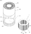
- a cylindrical filter body 10 is illustrated.
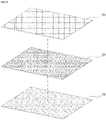
- the cylindrical filter body 10 may be made by rolling a thin plate-shaped filter base material, and a plate-shaped structure in which the filter body 10 is unfolded can be seen in FIG. 2 . Accordingly, the filter body 10 is a thin and flexible material, and thus may be used in various shapes.
- the filter body 10 may have a pleated shape, and such a pleated shape may function to increase the surface area of the filter body 10 so as to increase dust collection efficiency.
- the filter body 10 has a pleated shape, and alternatively, the filter body 10 may be made without pleats.
- the filter body 10 of the embodiment may be composed of three layers. Three-layered base materials may be laminated on each other and may be used as one part. Each of these three-layered base materials may be made of a thin material like a kind of fabric, and thus the entire thickness of the three-layered base materials may be thin. Accordingly, the air purification filter may be flexible and may be changed into various shapes as illustrated in FIGS. 1 and 2 and may have even a pleated shape.
- the filter body 10 of the present disclosure is illustrated to be unfolded.
- pleats may be formed on the filter body 10 having a planar structure, and the filter body 10 may be rolled in a cylindrical shape (an example of FIG. 1 ) or may be extended long in one direction (an example of FIG. 2 ) to be used.
- FIG. 3 a portion of the second electrode layer 70 constituting the filter body 10 is illustrated to be folded.
- the filter body 10 may be composed of three layers, and a filtering layer 30 which collects and filters minute particles may be located in the center of the three layers, and a pair of electrode layers is superimposed on the opposite sides of the filtering layer 30, respectively. Accordingly, the three base materials may be bonded on each other while being laminated on each other, or may be maintained to be coupled to each other by various methods, such as laser welding, etc.
- the pair of electrode layers coupled to the opposite sides of the filtering layer 30, respectively may include the first electrode layer 50 and the second electrode layer 70.
- Power may be applied to at least any one of the first electrode layer 50 and the second electrode layer 70, and power of opposite polarity may be applied to the remaining one of the first electrode layer 50 and the second electrode layer 70 or the remaining one may be grounded, so polarization may be generated through an electric field in the filtering layer 30 located between the first electrode layer 50 and the second electrode layer 70.
- a power supply part 230 of the air purifier 200 (see FIG. 8 ) may be electrically connected to at least any one of the first electrode layer 50 and the second electrode layer 70.
- the power supply part 230 may be provided in the air purifier 200.
- the first electrode layer 50 or the second electrode layer 70 may be naturally connected to the power supply part 230. This will be described again below.
- a polarization state before power is applied to the filter body 10 of the present disclosure ( FIG. 5(a) ) and a polarization state after power is applied to the filter body 10 of the present disclosure ( FIG. 5(b) ) are expressed as conceptual diagrams.
- the filtering layer 30 which is a dielectric may be maintained to be unpolarized.
- the filtering layer 30 when an anode (+) is applied to the first electrode layer 50 and a cathode (-) is applied to the second electrode layer 70, the filtering layer 30 is dielectrically polarized. Furthermore, dust particles may be dielectrically polarized by an electric field formed in the filtering layer 30 due to the dielectric polarization. That is, electrically charged dust particles may be subjected to Coulombic force. Accordingly, attraction may be generated between the dust particles and the filtering layer 30 separated therefrom, so the dust particles may be adsorbed on the filtering layer 30. Accordingly, the filtering layer 30 may have a higher collection efficiency for all particle diameters than a filter using a mechanical method.
- ⁇ 0 refers to a dielectric constant in vacuum
- ⁇ r refers to a relative dielectric constant
- E refers to electric field strength. That is, the electric field strength may be proportional to a voltage V applied to the filtering layer 30 and inversely proportional to an electrode gap d.
- the filtering layer 30 which is a dielectric
- the filtering layer 30 is made of a very thin material, so the electric field strength is greatly affected by the applied voltage V. Accordingly, a filter having a high performance may be embodied by increasing an applied voltage V.
- connection module 100 or 100' when insulation is improved through the connection module 100 or 100', a relatively large voltage may be applied between the first electrode layer 50 and the second electrode layer 70, and the filtering performance of the filtering layer 30 may be improved, and thus even if fine dust particles are continuously attached to and accumulated on the inside of the filter, the activity of electrostatic force of the filter may be constantly maintained.
- the filtering layer 30 may have a thin planar structure made of a dielectric material.
- a fibrous or particulate dielectric including synthetic organic polymers, natural organic polymers, and inorganic materials may be used.
- synthetic organic polymers may include polycarbonate, polyester, polyethylene, polyamide, polypropylene, polystyrene, polytetrafluoroethylene, polyvinyl alcohol, and polyvinyl chloride
- natural organic polymers may include cellulose, paper (DRY), cotton, and silk
- inorganic materials may include glass, silica, carbon, and alumina.
- the first electrode layer 50 laminated on the filtering layer 30 may be configured by interlacing the multiple strands of insulated wires 51 which are laminated on a side of the filtering layer 30 and can receive power. More precisely, the first electrode layer 50 may have a thin planar structure like the filtering layer 30, and may be a kind of fabric material formed by interlacing the multiple strands of insulated wires 51.
- the insulated wire 51 may be configured such that a surface thereof is covered and insulated, and an inner core wire thereof is configured as a conductive material.
- the insulated wire may be configured as an enameled copper wire.
- the enameled copper wire refers to a wire insulated in such a manner that insulating enamel is baked and attached on a copper wire to make an insulating film.
- the insulated wire 51 preferably has a diameter of 0.05 mm to 0.2 mm. This is because the insulated wire 51 has an excessively large resistance when the diameter is less than 0.05mm, and is thick when the diameter exceeds 0.2mm, so flexibility of the first electrode layer 50 decreases.
- the insulated wires 51 may use ready-made wires that have already been covered and manufactured.
- the first electrode layer 50 may be configured (i) by interlacing the multiple strands of insulated wires 51 alone, or (ii) by interlacing the multiple strands of insulated wires 51 and the support lines 53.
- the interlacing means tying multiple materials (the insulated wires 51 or the support lines 53) into multiple strands of materials in lines, arranging the materials side by side, or combining the materials in a way such as weaving, as will be described below.
- the support lines 53 may be made of insulating materials, and may be disposed between the insulated wires 51 and may function to maintain the shape of the first electrode layer 50 and reinforce strength thereof.
- Each of the support lines 53 may have an elongated structure like each of the insulated wires 51, and since the support lines are very thin, the support lines may be interlaced with the insulated wires 51 to make a kind of fabric material.
- the support line 53 may be made of a polymer-based material such as polyethylene (PE), polypropylene (PP), and polystyrene (PS), etc., and may be a polyamide material. Of course, the support line 53 may be made of various insulating materials in addition to the materials.
- PE polyethylene
- PP polypropylene
- PS polystyrene
- the first electrode layer 50 may be made to be flexible by interlacing the insulated wires 51 and the support lines 53 such that the insulated wires 51 and the support lines 53 extend in different directions.
- the first electrode layer 50 may be configured by weaving the insulated wires 51 and the support lines 53. That is, the first electrode layer 50 may be manufactured in a way in which a fabric is made.
- the first electrode layer 50 may be made by weaving the insulated wires 51 and the support lines 53 such that the insulated wires 51 and the support lines 53 constitute weft and warp yarns, respectively.
- the first electrode layer 50 is illustrated to be made like one fabric material made by weaving the insulated wires 51 which are weft yarns and the support lines 53 which are warp yarns. Additionally, holes which are empty spaces may be formed between the insulated wires 51 and the support lines 53, and FIG. 7 illustrates a portion of the first electrode layer 50 by enlarging the first electrode layer 50, and these holes may be very small and may be difficult to be seen with the naked eye.
- the first electrode layer 50 of the present disclosure may be made by weaving the insulated wires 51 and the support lines 53, and may be rapidly manufactured by using a weaving device, and even a first electrode layer 50 having a large area may be manufactured.
- the support lines 53 may be added to the first electrode layer 50, but the first electrode layer 50 may be made by weaving the insulated wires 51 alone.
- the first electrode layer 50 may be made like a kind of fabric material when the insulated wires 51 and the support lines 53 are woven together, so as illustrated in FIG. 7 , through the regular arrangement of fabrics, the entirety of the electrode layer may be maintained to have a predetermined thickness and be insulated. Furthermore, since the first electrode layer is made by weaving, the first electrode layer 50 may have a very low air pressure differential depending on a location thereof, and may maintain a shape thereof.
- the insulated wires 51 and the support lines 53 may not have similar proportions, but the support lines 53 may constitute weft and warp yarns, and the insulated wires 51 may constitute only a portion of the weft or warp yarns, together with the support lines 53. That is, the insulated wires 51 constitute some of the weft yarns, but the support lines 53 constitute most of the weft and warp yarns. In this case, compared to the embodiment of FIG. 7 , although an electric field strength generated when power is applied is small, manufacturing costs may be reduced and the strength of the first electrode layer 50 may be increased according to the type of the support lines 53.
- the entire area of the first electrode layer 50 is woven, but alternatively, only a portion of the first electrode layer 50 may be woven, and a remaining part thereof may not be woven or may be finished by bonding or taping.
- the first electrode layer 50 woven in this manner may be flexible like a kind of fabric material and each of thin flexible insulated wires 51 may be pre-insulated, so even if the first electrode layer is crumpled, the risk of insulation breakdown thereof may be very low. Accordingly, the filter body 10 including the first electrode layer 50 may be used by being folded into various shapes. For example, as illustrated in FIGS. 1 and 2 , the filter body 10 has a folded part V due to pleats, but the filtering layer 30, the first electrode layer 50, and the second electrode layer 70 may be all made of flexible materials, so the filter body 10 may be made in various shapes without the risk of insulation breakdown.
- the first electrode layer 50 may be made in various ways other than weaving.
- the first electrode layer 50 may be made as a knitted fabric by knitting.
- the first electrode layer 50 may be made by using various processing methods such as a twill weave, a satin weave, a double weave, a doup weave, and a fancy weave.
- the first electrode layer 50 having a planar structure may be made in such a manner that the multiple strands of insulated wires 51 and the support lines 53 are mixed with each other such that the multiple strands of insulated wires 51 and the support lines 53 extend in parallel to each other, and opposite edges thereof or four corners thereof are fixed.
- a conductive member 55 may be connected to the first electrode layer 50.
- the conductive member 55 may be considered as a kind of terminal for applying external power to the first electrode layer 50, and may be connected to each of the opposite end parts of the first electrode layer 50, or only to any one end part thereof as illustrated in FIG. 3 .
- the conductive member 55 may be made of a thin plate-shaped conductive material, and may be connected to the edge of the first electrode layer 50. Accordingly, the conductive member 55 may be connected to an end of each of multiple insulated wires 51 constituting the first electrode layer 50 in a direction crossing the end so as to allow current to flow to the multiple insulated wires 51. Accordingly, when power of the power supply part 230 is applied to the conductive member 55, the conductive member 55 may transmit power simultaneously to the multiple strands of insulated wires 51.
- the conductive member 55 may be made of a conductive material, and for example, may be made of thin sheets of stainless steel, aluminum, and copper, etc., or may be configured as a conductive tape. Furthermore, the conductive member 55 may be coupled to the insulated wires 51 by welding or conductive paste 140. Additionally, the conductive member 55 may be insulated except for parts connected to the power supply part 230 and the insulated wires 51.
- the conductive member 55 may include a pair of the conductive members and may be connected to the first electrode layer 50 and to the second electrode layer 70. Meanwhile, the conductive member 55 may be a part of the connection module 100 or 100'.
- a module terminal 120 of the connection module 100 or 100' to be described below may be coupled to the conductive member 55, or the conductive member 55 may be a part of the module terminal 120. Additionally, the module terminal 120 may take the place of the conductive member 55, and the conductive member 55 may be omitted.
- the connection module 100 or 100' will be described again below.
- the second electrode layer 70 may be laminated on a side of the filtering layer 30 opposite to the side of the first electrode layer, and, together with the first electrode layer 50, may create electrostatic induction in the filtering layer 30.
- the second electrode layer 70 like the first electrode layer 50, may be made of a thin flexible material like a fabric material, and may include a conductive material to form an electric field.
- a polarity opposite to the polarity of the first electrode layer 50 may be applied to the second electrode layer 70 from the power supply part 230, or the second electrode layer 70 may be grounded without being connected to the power supply part 230.
- an anode (+) may be applied to the first electrode layer 50
- a cathode (-) may be applied to the second electrode layer 70, or the second electrode layer 70 may be grounded.
- the surface of the second electrode layer 70 may be insulated like the first electrode layer 50, and a core wire thereof may be made to be flexible in such a manner that an insulated wire 51 which is electrically conductive and a support line 53 which is an insulator are interlaced together in different directions from each other. As described above, the second electrode layer 70 may be manufactured by weaving.
- the second electrode layer 70 is made of a fabric material containing a conductive material.
- the second electrode layer 70 may be a fabric material whose surface is coated with carbon.
- carbon coating may be performed on the surface of the second electrode layer 70, so the second electrode layer 70 may be conductive.
- the second electrode layer is not as conductive as the first electrode layer 50 composed of the insulated wires 51, the second electrode layer may have conductivity sufficient to polarize the filtering layer 30 located between the first electrode layer 50 and the second electrode layer.
- the second electrode layer 70 may be coated with metal instead of carbon.
- the second electrode layer 70 is made by coating the surface of a nonwoven base material with carbon.
- an insulated section 73 in which a conductive material is omitted may be formed on the edge of the second electrode layer 70.
- Such an insulated section 73 which is a section having no conductive material, may be considered, for example, as a part of the second electrode layer 70 in which carbon coating is omitted.
- Such an insulated section 73 may be an insulation distance between the pair of electrode layers. Accordingly, the air purification filter of the present disclosure may have the insulated section 73 without a need for an additional insulation work, so insulation may be securely realized between the pair of electrode layers.
- each of the insulated wires 51 constituting the first electrode layer 50 may be exposed to the outside without being coated, and may be in contact with the second electrode layer 70, and thus current may flow therebetween.
- insulation breakdown may occur between the first electrode layer 50 and the second electrode layer 70, and thus there is a possibility that the filtering layer 30 is no longer polarized. Accordingly, this possibility may be reduced by such an insulated section 73.
- the insulated section 73 may extend along the edge of each of the upper and lower surfaces of the second electrode layer 70 adjacent to the first electrode layer 50. Of course, the insulated section 73 may be formed even on the first electrode layer 50 or may be formed only on the first electrode layer 50. Such an insulation section 73 may function to insulate the filter 1 together with the connection module 100 or 100' to be described later.
- the first electrode layer 50 may be configured by interlacing the insulated wire 51 and the support line 53, and the second electrode layer 70 may be made of a fabric material containing a conductive material.
- both the first electrode layer 50 and the second electrode layer 70 may be made of fabric materials containing conductive materials, that is, of fabric materials which are coated with carbon.
- the first electrode layer 50 and the second electrode layer 70 may have lengths different from each other, with the filtering layer 30 placed therebetween, so an insulation step part A may be made between the first electrode layer 50 and the second electrode layer 70.
- Such an insulation step part A may function to increase the insulation performance of the filter by spacing neighboring end parts of the first electrode layer 50 and the second electrode layer 70 apart from each other. This will be described again below.
- the filter 1 may be configured by coupling the connection module 100 or 100' to the filter body 10 described above.
- a reference numeral 5 refers to a guide plate maintaining the shape of the filter 1.
- the frame of the air purifier 200 is constituted by a purifier housing 201, and in this embodiment, the purifier housing 201 has a cylindrical shape.
- Air discharge holes 203 are formed in the upper end of the purifier housing 201 so as to discharge air filtered through the filter 1 after being introduced into the air purifier.
- a filter installation space 210 may be defined inside the purifier housing 201.
- the filter installation space 210 may a kind of empty space and may have a cylindrical shape. Accordingly, this embodiment, as illustrated in FIGS. 8 and 9 , the filter 1 having a cylindrical shape may be mounted in the filter installation space 210.
- the filter 1 may be inserted into and mounted to the filter installation space 210, and a structure and a cover for fixing or separating the filter 1 are omitted.
- the purifier housing 201 and the filter installation space 210 may not have cylindrical shapes but hexahedral shapes.
- the filter 1 having the structure of a flat plate may be installed in the air purifier 200.
- a mounting surface 212 may be provided on the bottom surface of the filter installation space 210 of the purifier housing 201.
- the mounting surface 212 may constitute a bottom surface on which the filter 1 is seated, and in the embodiment, may have a disk structure corresponding to the shape of the purifier housing 201.
- a mounting surface having a shape corresponding to the shape of the mounting surface 212 may be provided even on a ceiling of the filter installation space 210 which is a side opposite to the mounting surface 212, and is not visible because of the angle of the air purifier illustrated in FIG. 8 .
- connection terminal may be provided in the filter installation space 210.
- the connection terminal may be in contact with and electrically connected to the terminal head 125 or 125' of the connection module 100 or 100' of the filter to be described below, and may be mounted in the filter installation space 210.
- the connection terminal may be connected to the power supply part 230 installed on the purifier housing 201 or may be grounded.
- the connection terminal may include a pair of connection terminals, and a first connection terminal of the connection terminals may be connected to the power supply part 230, and a second connection terminal 220 may be connected to the power supply part 230 by having a polarity opposite to the polarity of the first connection terminal or may be grounded. In FIG. 8 , only the second connection terminal 220 is visible, and the first connection terminal located on the ceiling of the filter installation space 210 is not visible.
- the first connection terminal which is connected to the power supply part 230, and the second connection terminal 220 which is connected to the power supply part 230 by having a polarity opposite to the polarity of the first connection terminal or is grounded may be installed in the filter installation space 210. Furthermore, when the filter 1 is installed in the filter installation space 210, a first connection module 100 and a second connection module 100' to be described below may be electrically connected to the second connection terminal 220 and the first connection terminal, respectively.
- the first connection terminal and the second connection terminal 220 may be located at different heights from each other.
- the second connection terminal 220 is installed on the mounting surface 212, and the first connection terminal is installed on the ceiling of the filter installation space 210, and is not shown in the drawing.
- the first connection terminal and the second connection terminal 220 may be respectively connected to a second module terminal 120 of the second connection module 100' and a first module terminal 120 of the first connection module 100 which will be described below, and the first module terminal 120 and the second module terminal 120 may protrude in directions opposite to each other and may be in contact with the first connection terminal and the second connection terminal 220.
- the first connection terminal and the second connection terminal 220 may be respectively installed on different positions by having different heights to match the heights of the first module terminal 120 and the second module terminal 120.
- any one of the first connection terminal and the second connection terminal 220 may also be configured to have a circular shape. That is, the first connection terminal or the second connection terminal 220 may be made in a circular shape corresponding to the filter body 10, and in this embodiment, both the first connection terminal and the second connection terminal 220 have circular shapes.
- the second connection terminal 220 may be made along a virtual circular extension line drawn by a second terminal head 125' protruding from the second connection module 100' to be described below while the second terminal head rotates relative to the center of the filter body 10 having a circular shape. Accordingly, even when the filter 1 is inserted in any direction, the filter 1 may be in contact with and electrically connected to the circular second connection terminal 220.
- a first terminal head 125 of the first connection module 100 and the second terminal head 125' of the second connection module 100' may protrude in directions opposite to each other, and the first connection terminal and the second connection terminal 220 may respectively extend to have circular shapes to be spaced apart from each other by corresponding to the heights of the first connection module 100 and the second connection module 100'.
- the first connection terminal may also be made along a virtual circular extension line drawn by the first terminal head 125 protruding from the first connection module 100 while the first terminal head 125 rotates relative to the center of the filter body 10 having a circular shape.
- first connection terminal and the second connection terminal 220 may be respectively provided along straight paths.
- the filter 1 has the structure of a flat plate as illustrated in FIG. 10
- the filter 1 may be inserted into the filter installation space 210 along the straight path, and thus the first connection terminal and the second connection terminal 220 may extend to be long along the straight paths according to the insertion paths of the filter.
- each of the first connection terminal and the second connection terminal 220 may have a busbar structure extending in one direction.
- the first connection terminal and the second connection terminal 220 may not extend to be long in one direction, but may respectively be short terminal structures located at positions corresponding to the second terminal head 125' of the second connection module 100' and the first terminal head 125 of the first connection module 100, respectively.
- the first terminal head 125 and the second terminal head 125' may be in contact with the second connection terminal 220 and the first connection terminal, respectively.
- the first connection terminal and the second connection terminal 220 may be configured such that the insertion direction of the filter is not specified.
- the first connection terminal may include a pair of first connection terminals which has different heights from each other or has different positions in left and right directions
- the second connection terminal 220 may also include a pair of second connection terminals which has different heights from each other or has different positions in left and right directions, respectively.
- the filter even when the filter 1 is inserted into the filter installation space 210 in a state of being turned in a left-to-right direction or in a vertical direction, the filter may be in contact with the first connection terminal and the second connection terminal 220.
- the filter may include the filter body 10 and the connection module 100 or 100', and since the filter body 10 has been described above, the connection module 100 or 100' will be described.
- the connection module 100 or 100' may be coupled to at least any one of the opposite ends of the filter body 10 so as to insulate an end of the filter body 10 from the outside and at the same time, may be electrically connected to the power supply part 230.
- connection module 100 or 100' may electrically connect any one of the first electrode layer 50 and the second electrode layer 70 to the power supply part 230, and may allow a peripheral part of the electrode layer except for a part thereof for the electrical connection to be insulated from the outside. Accordingly, the connection module 100 or 100' may completely cover and insulate an end part of the insulator of the electrode layer exposed to the outside, and thus may securely insulate the electrode part of the filter. Particularly, even if two electrodes are close to each other due to the thin thickness of the filter, the connection module 100 or 100' may realize complete insulation between the two electrodes. Accordingly, the connection module 100 or 100' may be considered as a kind of connector.
- connection module 100 or 100' may be coupled to the filter body 10 and may, together with the filter body, constitute the filter. As described below, the connection module may be coupled to each of the opposite sides of the filter body 10, or only to any one side thereof.
- the connection module 100 or 100' may insulate the end part of the filter body 10 from the outside. As illustrated in FIGS. 8 and 9 , in the case in which the filter 1 has a cylindrical shape, the connection module 100 or 100' may allow the opposite ends of the filter body 10 to be insulated from each other. In this case, even if the connection module 100 or 100' is provided on any one end of the filter body 10, the any one end thereof may be insulated from a remaining end thereof.
- the end part of the filter body refers to a part of a conductor, which is exposed to the outside, on an end of each of the first electrode layer 50 and the second electrode layer 70 constituting the filter body 10.
- a core wire thereof which is a conductor may be exposed to the outside, and an end part of a carbon coated part constituting the second electrode layer 70 may also be exposed to the outside.
- the entirety of the carbon coated part of the second electrode layer 70 including the end part thereof may be exposed to the outside.
- a conductor is made of a conductive material, and in the first electrode layer 50, the core wire of the insulated wire 51 may be a conductor, and in the second electrode layer 70, the entirety of the carbon coated part thereof may be a conductor.
- connection module 100 or 100' may include the first connection module 100 and the second connection module 100' which have the same structures. Accordingly, the parts having the same structures are given the same reference numerals in the drawings, and the first connection module 100 will be described hereinbelow.
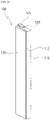
- the frame of the first connection module 100 may be constituted by module housings 110 and 130.
- Each of the module housings 110 and 130 may be made of an insulating material, and may insulate an end part of the filter body 10 connected to the first connection module 100.
- the module housing 110 or 130 may have a hexahedral shape extending long in one direction, wherein the length of the module housing 110 or 130 may be greater than or equal to the length of the filter body 10.
- the length of the module housing 110 or 130 is a vertical length relative to FIG. 11 .
- the module housing 110 or 130 may include two bodies, and a connection space 113 may be defined between the two bodies.
- the module housing 110 or 130 may include a first housing 110 and a second housing 130.
- the first housing 110 and the second housing 130 may be assembled with each other to constitute one body, and the second housing 130 may be considered as a kind of cover.
- the end part of the filter body 10 may be inserted between the first housing 110 and the second housing 130.
- connection space 113 may be defined inside the first housing 110.
- the connection space 113 may extend in the longitudinal direction of the first housing 110, and may have a shape recessed toward the inside of the first housing 110.
- the connection end part 51' of the first electrode layer 50 or the connection end part 70' of the second electrode layer 70 which is the exposed end part of the conductor of the first electrode layer 50 or the second electrode layer 70 may be inserted into the connection space 113.
- the module terminal 120 may be installed in the connection space 113, and thus the connection end part may be electrically connected to the module terminal 120 by being laminated thereon.
- the connection end part 51' or 70 indicates a part of the conductor exposed to the outside.
- a first insulation surface 112 may be provided on a surface of the first housing 110 facing the second housing 130.
- the first insulation surface 112 may be adjacent to the connection space 113 and may have the height of a bottom surface different from the height of the bottom surface of the connection space 113.
- the first insulation surface 112 may be in close contact with a second insulation surface 132 of the second housing 130.
- the connection end part 51' of the first electrode layer 50 is inserted into the connection space 113
- the connection end part 70' of the second electrode layer 70 may be inserted between the first insulation surface 112 and the second insulation surface 132 so as to be covered therewith.
- connection end part 70' of the second electrode layer 70 when the connection end part 70' of the second electrode layer 70 is inserted into the connection space 113, the connection end part 51' of the first electrode layer 50 may be inserted between the first insulation surface 112 and the second insulation surface 132 so as to be covered therewith. Accordingly, the first connection module 100 may be coupled to an end part of the electrode layer so as to insulate the electrode layer.
- An insulating material may be applied to the electrode layer for insulation, or an end part thereof to which current easily flows is not required to be insulated.
- the first housing 110 may have a terminal hole 115.
- the terminal hole 115 may be a part formed through a portion of the first housing 110 in the longitudinal direction of the connection space 113.
- the terminal hole 115 may be located on the upper surface of the first housing 110.
- the first terminal head 125 connected to the module terminal 120 may protrude through the terminal hole 115 to the outside. More precisely, the module terminal 120 may be inserted through the terminal hole 115 into the connection space 113.
- the terminal hole 115 may not be formed through the first housing 110, but may be space open upward by further extending the connection space 113 of the first housing 110 upward.
- the module terminal 120 may be mounted to the first housing 110.
- the module terminal 120 which is a conductor, may be electrically connected to the connection end part 51' or 70' of the first electrode layer 50 or the second electrode layer 70 of the filter body 10 in the connection space 113 of the first housing 110.
- the remaining portion of the module terminal 120 except for the terminal head 125 protruding through the terminal hole 115 may be covered and insulated.
- the module terminal 120 may be seated on the bottom of the connection space 113 defined in the module housing 110 or 130 of the first connection module 100, and the connection end part 51' or 70' of the conductor of any one of the first electrode layer 50 and the second electrode layer 70 may be laminated on the surface of the module terminal 120.
- the module terminal 120 may extend long in the longitudinal direction of the connection space 113.
- the module terminal 120 which has the structure of a metal flat plate, may have the shape of a kind of busbar.
- the module terminal 120 may be connected to the connection end part 51' of the first electrode layer 50 or the connection end part 70'of the second electrode layer 70.
- the module terminal 120 may be coupled transversely to the connection end part 51' of the conductor, whose conductive material is exposed to the outside, of the first electrode layer 50 or the second electrode layer 70 which receives power from the power supply part 230 so as to polarize the filtering layer 30.
- the end parts 51' of the multiple strands of insulated wires 51 may be simultaneously connected to the module terminal 120.
- the first connection module 100 may have the second housing 130.
- the second housing 130 may be assembled with the first housing 110, and when the second housing 130 is assembled with the first housing 110, the connection space 113 may be covered.
- the second housing 130 may be made of an insulated material like the first housing 110.
- the second housing 130 may be press-fitted into the first housing 110, and alternatively, may have a separate coupling protrusion so as to be coupled to the first housing.
- the first housing 110 and the second housing 130 may be assembled with each other by sliding or by separate fasteners.
- the second housing 130 may have the second insulation surface 132.
- the second insulation surface 132 may be a part in close contact with the first insulation surface 112 of the first housing 110.
- the connection end part 51' of the first electrode layer 50 is inserted into the connection space 113, the connection end part 70' of the second electrode layer 70 may be inserted between the first insulation surface 112 and the second insulation surface 132 so as to be covered.
- a press block 135 may protrude on the second housing 130.
- the press block 135 may protrude from the second housing 130 toward the connection space 113.
- the press block 135 may advance into the connection space 113.
- the press block 135. When the first housing 110 and the second housing 130 are assembled with each other, the module terminal 120 and the connection end part 51' or 70' of a conductor of any one of the first electrode layer 50 or the second electrode layer 70, which are laminated in the connection space 113, may be pressed by the press block 135. Accordingly, the press block 135 may allow electrical connection between the module terminal 120 and the filter body 10 to be stably performed.
- connection module 100 or 100' may include the first connection module 100 and the second connection module 100'coupled to the opposite sides of the filter body 10, respectively. Furthermore, the first connection module 100 and the second connection module 100' may be electrically connected to the first electrode layer 50 and the second electrode layer 70, respectively.
- the first connection module 100 and the second connection module 100' may be in close contact with each other. Accordingly, the first connection module 100 and the second connection module 100' may have a structure for assembly thereof with each other, and although not shown, may have assembly structures such as press-fit protrusions, hooks or magnets. In this case, the filter body 10 may not be required to have a separate structure so as to maintain a rolled cylindrical shape thereof.
- FIGS. 13 and 14 respectively, states in which the filter body 10 and the first connection module 100 are assembled with each other and the filter body 10 and the second connection module 100' are assembled with each other are illustrated as cross-sectional views.
- FIG. 13 illustrates a state in which the connection end part 51' of the first electrode layer 50 in the filter body 10 is laminated on the module terminal 120 of the first connection module 100
- FIG. 14 illustrates a state in which the connection end part 70' of the second electrode layer 70 in the filter body 10 is laminated on the module terminal 120 of the second connection module 100'.
- connection end part 51' of the first electrode layer 50 is seated in the connection space 113 and is electrically connected to the module terminal 120
- the module terminal 120 may be located on the bottom of the connection space 113, and the filter body 10 may be seated on the module terminal, and the first electrode layer 50, the filtering layer 30, and the second electrode layer 70 may be sequentially laminated thereon. Accordingly, the first electrode layer 50 may be electrically connected to the module terminal 120.
- the remaining part of the filter body 10 more precisely, the peripheral part of the connection end part 51' of the first electrode layer 50 may be covered between the first housing 110 and the second housing 130 so as to be insulated.
- the connection end part 70' of the second electrode layer 70 may be located between the first housing 110 and the second housing 130 and may be pressed between the first insulation surface 112 and the second insulation surface 132.
- the conductive paste 140 may be present between the module terminal 120 and the connection end part 51' of the first electrode layer 50. That is, the conductive paste 140 may be applied to a position between the module terminal 120 and the connection end part 51' of the first electrode layer 50 and thus the module terminal 120 and the first electrode layer 50 may be electrically connected to each other. In FIG. 13 , the conductive paste 140 can be seen to have a thin layer. Of course, the conductive paste 140 may not be necessarily applied but may be sprayed, or solidified materials thereof may be stacked to be inserted into the position between the module terminal and the connection end part.
- the conductive paste 140 is a composite material in which functional fillers such as metal powder or inorganic oxide are uniformly dispersed in a resin solution having fluidity, and is manufactured by dispersing metal particles with a diameter of several hundred to several thousand nanometers to an adhesive resin. Accordingly, the conductive paste 140 may function as an adhesive coupling the module terminal 120 to the connection end part 51' of the first electrode layer 50, and may function to electrically connect the module terminal 120 with the connection end part 51' .
- the module terminal 120 and the connection end part 51' of the first electrode layer 50 may be in close contact with each other only by the press block 135 of the second housing 130, and may be coupled to each other by a method such as laser welding.
- connection end part 51' of the first electrode layer 50 may be located in the connection space 113, but a connection end part which is the conductor of the second electrode layer 70 may be located at a position away from the connection space 113. That is, a portion of an end part of the second electrode layer 70 may be located between the first insulation surface 112 and the second insulation surface 132. Furthermore, the connection end part 51' of the first electrode layer 50 and the connection end part 70' of the second electrode layer 70 may be spaced apart from each other to naturally form an insulation section therebetween.
- connection end part 51' of the first electrode layer 50 and the connection end part 70' of the second electrode layer 70 may have different heights from each other and may have different positions in left and right directions, respectively, so a stable insulation therebetween may be realized. Furthermore, the connection end part 51' of the first electrode layer 50 may be considered to be blocked from the connection end part 70' of the second electrode layer 70 by the press block 135.
- a step may be made since lengths of the first electrode layer 50 and the second electrode layer 70 are different from each other. That is, the lengths of end parts of the first electrode layer 50 and the second electrode layer 70 may be different from each other, and thus the insulation step part A may be formed between the first electrode layer 50 and the second electrode layer 70.
- the insulation step part A may be naturally made since the lengths of the first electrode layer 50 and the second electrode layer 70 are different from each other. Alternatively, when the lengths of the first electrode layer 50 and the second electrode layer 70 are the same but only the connection end part 51' of the first electrode layer 50 is placed in the connection space 113, the insulation step part A may be made.
- connection end part 51' of the first electrode layer 50 may be seated in the connection space 113 and be connected to the module terminal 120, and the connection end part 70' of the conductor of the second electrode layer 70 which has a shorter length may be located at a position away from the connection space 113 and may be covered by the module housing 110 or 130.
- the second connection module 100' is configured in a direction opposite to the direction of FIG. 13 . That is, the connection end part 70' of the second electrode layer 70 may be located in the connection space 113, but the connection end part 51' which is the conductor of the first electrode layer 50 may be located at a position away from the connection space 113. That is, a portion of the end part of the first electrode layer 50 may be located between the first insulation surface 112 and the second insulation surface 132. Furthermore, the connection end part 51' of the first electrode layer 50 and the connection end part 70' of the second electrode layer 70 may be spaced apart from each other to naturally form the insulation step part A.
- a reference numeral 58 is an insulated end part made on the connection end part 51' of the first electrode layer 50.
- the insulated end part 58 is insulated by covering the connection end part 51' of the first electrode layer 50.
- the connection end part 51' of the first electrode layer 50 may be covered with an insulating tape so as to be insulated from a surrounding area.
- the first connection module 100 and the second connection module 100' may be coupled to the opposite sides of the filter body 10, respectively. Furthermore, the first terminal head 125 protruding from the first connection module 100 and the second terminal head 125' protruding from the second connection module 100' may protrude in directions opposite to each other. Accordingly, an insulation distance between the first connection module 100 and the second connection module 100' may increase, and consequently, current may not easily flow between the first connection module 100 and the second connection module 100'.
- the module housing 110 or 130 includes the first housing 110 and the second housing 130.
- the module housing 110 or 130 may be configured as one body, and in this case, the second housing 130 may be omitted, or the first housing 110 and the second housing 130 may be connected integrally to each other by an injection hinge. Without the second housing 130, the module terminal 120 of the connection space 113 may be exposed to the outside, but remaining parts may be surrounded by insulating materials, and may secure some degree of insulation.
Landscapes
- Chemical & Material Sciences (AREA)
- Chemical Kinetics & Catalysis (AREA)
- Engineering & Computer Science (AREA)
- Life Sciences & Earth Sciences (AREA)
- Geology (AREA)
- Inorganic Chemistry (AREA)
- Textile Engineering (AREA)
- Ceramic Engineering (AREA)
- Electrostatic Separation (AREA)
- Filtering Materials (AREA)
Abstract
Description
- The present disclosure relates generally to an air purification filter and an air purifier. More particularly, the present disclosure relates to an air purification filter in which electrostatic force is activated by applying high voltage to the filter, and to an air purifier to which such a filter is mounted.
- An air purifier is understood as a device that sucks in and purifies polluted air, and then discharges the purified air. For example, an air purifier may include a blower which introduces external air into the air purifier, and filters which can filter out dust and bacteria in the air.
- Among these filters, a dielectric filter is electrostatically treated during manufacturing so as to have electrostatic property. The filter treated electrostatically in this manner can electrically adsorb minute particles and thus can have a lower pressure loss and higher collection efficiency than a conventional mechanical filter.
- In general, particles suspended in air contain a lot of positively or negatively charged particles, and the charged particles are strongly adsorbed to a dielectric filter which is electrostatically treated, so the collection efficiency of the filter is increased.
- However, as the usage time of the filter is accumulated and the collected dust increases, the loss of electrostatic force occurs, and the collection efficiency of the filter also decreases. Accordingly, even if a filter is electrostatically treated, the filter has limited collection efficiency due to increase in usage time thereof.
- Particularly, indoor air may contain multiple oil particles, and a general air purifier has a problem in that the air purifier is difficult to effectively remove oil particles contained in air. When oil particles are collected in a filter installed to remove foreign matter, an electrostatic property of the filter is rapidly reduced and the life of the filter is rapidly reduced.
- In order to solve this, a filter may be used in which a power supply is connected to the filter, and an electrostatic field generated by a voltage differential between two electrodes is used. In this case, a dielectric filter is located in the electrostatic field between the two electrodes and performs a collection function.
- Among prior arts, there is an art (
Korean Patent Application Publication No. 10-2011-0128465 - Particularly, in prior arts in which electrostatic properties are imparted to a dielectric filter, when the filter is rolled to have a cylindrical shape, opposite ends thereof in contact with each other may be energized, so it is difficult to make the filter cylindrical.
- In addition, there is a disclosed prior art (
Korean Patent Application Publication No. 10-2010-0082025 - Furthermore, there is a disclosed prior art (
Korean Patent Application Publication No. 10-2019-0068327 - The present disclosure has been made to solve the above problems occurring in the prior art, and the present disclosure is intended to ensure that two electrodes are stably insulated therebetween through a connection module even if the two electrodes are close to each other due to thin thickness of a filter.
- The present disclosure is further intended to ensure that power is evenly supplied to an entire filter through the connection module.
- The present disclosure is still further intended to ensure that the filter may be mounted in various directions with no limit to a direction when the filter is mounted to an air purifier.
- In order to accomplish the above objectives, according to an aspect of the present disclosure, an air purification filter of the present disclosure includes a filtering layer configured as a dielectric which collects minute particles, a pair of electrode layers laminated respectively on opposite sides of the filtering layer and configured to receive power so as to generate polarization through an electric field in the filtering layer, and a connection module. The connection module may be coupled to at least any one of the opposite ends of the pair of electrode layers such that the coupled portion of the connection module is insulated from the outside, and the coupled portion is electrically connected with an external power supply part. Accordingly, the connection module may be coupled to at least any one end part of the pair of electrode layers, and thus a part of an insulator, which is exposed to the outside, of the at least any one end part of the pair of electrode layers may be electrically connected to the power supply part, and a remaining part thereof may be insulated from the outside, and particularly, even if two electrodes are close to each other due to thin thickness of the filter, the connection module may realize complete insulation between the two electrodes.
- In addition, connection end parts of conductors exposed to the outside may be provided on the electrode layer such that the each of connection end parts thereof is electrically connected to the power supply part, and the connection module may be coupled to the electrode layer so as to cover the connection end part. Accordingly, power may be supplied simultaneously to the conductors of the electrode layer from various positions, and the filter may realize an even performance.
- In addition, the connection module may include a module housing having a connection space defined therein and made of an insulated material, and a module terminal installed in the connection space of the module housing and electrically connected to any one of the pair of electrode layers inserted into the connection space, with a terminal head protruding toward the outside of the connection space and being connected to the power supply part. The protruding terminal head may be in contact with a connection terminal provided inside an air purifier so as to receive power.
- In addition, in any one of the pair of electrode layers, a connection end part of a conductor thereof exposed to the outside may be seated in the connection space so as to be electrically connected to the module terminal, and in a remaining one of the pair of electrode layers, the connection end part of a conductor may be located at a position away from the connection space. That is, when the connection module is assembled with the end parts of the pair of electrode layers, any one electrode layer may be electrically connected to the module terminal of the connection module, but a remaining electrode layer may be located at a position away from the module terminal without being in contact therewith so as to be insulated therefrom.
- The module terminal may be seated on the bottom of the connection space provided in the module housing of the connection module, and in any one electrode layer of the pair of electrode layers, the connection end part of a conductor may be laminated on the surface of the module terminal. Conductive paste may be applied between the module terminal seated in the connection space of the module housing and the connection end part of a conductor of any one of the pair of electrode layers laminated on the module terminal. Accordingly, electrical connection between the filter body and the connection module may be easily and stably performed.
- The connection module may include a first connection module and a second connection module coupled respectively to the opposite sides of a filter body including the filtering layer and the pair of electrode layers, wherein the first connection module and the second connection module may be electrically connected respectively to a first electrode layer and a second electrode layer constituting the pair of electrode layers. Accordingly, both of the opposite sides of the filter body may be insulated from the outside and, simultaneously, may be electrically connected.
- When the first connection module and the second connection module are coupled to the opposite sides of the filter body, respectively, a first terminal head protruding from the first connection module and a second terminal head protruding from the second connection module may protrude in directions opposite to each other. Furthermore, a first connection terminal and a second connection terminal corresponding to the second terminal head and the first terminal head, respectively, may be installed inside a mounting space of the air purifier, and an insulation distance may be sufficiently secured between two electrodes of the filter.
- At least any one of the first electrode layer and the second electrode layer may be configured by interlacing multiple strands of insulated wires, and the first electrode layer may be configured by interlacing the multiple strands of insulated wires and multiple strands of support lines which are insulators, and the insulated wires and support lines of the first electrode layer may be woven together. Accordingly, the electrode layer may be configured by interlacing multiple strands of insulated wires, and as the insulated wires, wires, which are completely pre-insulated, such as enameled copper wires may be used, so the insulation performance of the filter may be improved and without need for an additional insulation work, the manufacturing of the filter may be facilitated.
- According to another aspect of the present disclosure, the air purifier of the present disclosure may include a purifier housing having a filter installation space defined therein, a power supply part installed in the purifier housing, and a filter configured to receive power from the power supply part when installed in the filter installation space. In this case, the connection module may be installed on the filter, and the first connection terminal connected to the power supply part and the second connection terminal may be installed in the filter installation space, the second connection terminal being connected to the power supply part by having a polarity opposite to the polarity of the first connection terminal or being grounded. When the filter is installed in the filter installation space, the first connection module and the second connection module may be electrically connected to the second connection terminal and the first connection terminal, respectively. Accordingly, the mounting of the filter to the air purifier may be easy.
- Furthermore, the filter may be formed by rolling the filter body including the filtering layer and the pair of electrode layers so as to have a cylindrical shape, and any one of the first connection terminal and the second connection terminal may be made along a virtual circular extension line drawn while the terminal head of the module terminal protruding from the connection module rotates relative to the center of the cylindrical filter. Accordingly, even if the filter is inserted into the mounting space in any direction, the terminal head may be in contact with and connected to the connection terminal, so there may be no limit to the insertion direction of the filter.
- The air purification filter and the air purifier including the same according to the present disclosure described above may have the following effects.
- According to the present disclosure, when the pair of electrode layers receives power and an electric field is formed therebetween, the collection performance of the filtering layer located therebetween may be improved through dielectric polarization. In this case, the connection module may be coupled to at least any one end part of the pair of electrode layers such that an exposed part of an insulator thereof is electrically connected to the power supply part and a remaining part thereof is insulated from the outside. Accordingly, according to the present disclosure, the exposed end part of the insulator may be completely covered so as to securely insulate the electrode part of the filter, and particularly, even if two electrodes thereof are close to each other due to the thin thickness of the filter, the connection module may realize complete insulation between the two electrodes, thereby improving the insulation performance of the filter.
- Furthermore, the connection module of the present disclosure may be coupled to an end part of the electrode layer, and may insulate the electrode layer, and accordingly, an insulated material is not required to be applied to the electrode layer for insulation thereof or it is not required to insulate end parts thereof which are easily energized, so the insulation work of the filter may be facilitated.
- In addition, in the present disclosure, the connection module may be connected to at least one of the pair of electrode layers, and the connection module may be connected transversely to the connection end part of the exposed conductor of an end part of each of multiple electrode layers so as to energize the electrode layers. Accordingly, power may be supplied simultaneously to the conductors of the electrode layers from various positions, and the filter may realize even performance.
- Furthermore, in the present disclosure, the connection module may include two housings having the module terminal made of a conductive material provided therebetween, and when an end part of each of the electrode layers constituting the filter is inserted into the housings, the end part thereof may be laminated on the module terminal so as to be electrically connected. Accordingly, in the process of assembling the housings constituting the connection module, the electrode layer and the connection module may be naturally electrically connected to each other, and the remaining part of the electrode layer may be insulated from the connection module, thereby facilitating the manufacturing of a power connection part for supplying power to the filter.
- Additionally, in the present disclosure, the pair of electrode layers constituting the filter may be manufactured to have different lengths from each other, and the connection end parts of the conductors, which are exposed to the outside, on the end parts of the electrode layers may have positions different from each other. Accordingly, when the connection module is assembled with the end parts of the pair of electrode layers, any one electrode layer may be electrically connected to the module terminal of the connection module, but a remaining electrode layer may be located at a position away from the module terminal without being in contact therewith so as to be insulated therefrom, thereby improving insulation work of the filter and insulation thereof.
- Accordingly, when the insulation of the filter is improved, a relatively large voltage may be applied to the electrode layer, and a filtering performance of the filtering layer may be improved, so even if fine dust particles are continuously attached and accumulated inside the filter, the activity of electrostatic force of the filter may be maintained to be constant. Furthermore, relative to the same efficiency of removing fine dust particles, the filter of the present disclosure may significantly reduce pressure loss, which is an air resistance characteristic, compared to an existing filter.
- In addition, the connection module of the present disclosure may extend along one direction of the filter, and the terminal head connected to the module terminal may protrude to the outside of the housing of the connection module. Accordingly, when the connection module is mounted to the air purifier, the terminal head may be naturally in contact with the connection terminal provided inside the mounting space to be electrically connected thereto. Accordingly, the installation of the filter may be facilitated.
- Particularly, in the first connection module and the second connection module electrically connected to the pair of electrode layers, respectively, the first terminal head and the second terminal head may protrude in directions opposite to each other, and in the mounting space of the air purifier, the first connection terminal and the second connection terminal corresponding to the second terminal head and the first terminal head, respectively, may be installed. Accordingly, an insulation distance may be sufficiently secured between the two electrodes of the filter.
- In addition, in the present disclosure, the connection terminal which is circular may be installed inside the mounting space in which the filter is mounted, and such a connection terminal may be made along a virtual circular extension line drawn while the terminal head of the module terminal protruding from the connection module rotates relative to the center of the cylindrical shaped filter. Accordingly, even if the filter is inserted into the mounting space in any direction, the terminal head may be in contact with and connected to the connection terminal, and thus there may be no limit to the insertion direction of the filter, thereby improving the assembly of the filter.
- Furthermore, the electrode layer may be configured by weaving multiple strands of insulated wires, and as the insulated wires, wires such as enameled copper wires which are completely pre-insulated may be used, thereby, improving the insulation performance of the filter, facilitating the manufacturing of the filter without need for an additional insulation work, and improving the performance of the filter due to improved conductivity.
-
-
FIG. 1 is a perspective view illustrating a body of an air purification filter of the present disclosure made in a cylindrical shape. -
FIG. 2 is a perspective view illustrating the body of the air purification filter of the present disclosure made in a plate shape. -
FIG. 3 is a top plan view illustrating an embodiment of the filter body of the present disclosure. -
FIG. 4 is a perspective view illustrated by disassembling materials constituting the filter body of the present disclosure according to the embodiment. - IGS. 5(a) and 5(b) respectively are conceptual diagrams illustrating states before and after a filtering layer constituting the filter body of the present disclosure according to the embodiment is polarized.
-
FIG. 6 is a top plan view illustrating another embodiment of the filter body of the present disclosure. -
FIG. 7 is a top plan view illustrated by enlarging the configuration of a first electrode layer constituting the filter body of the present disclosure. -
FIG. 8 is a perspective view illustrating a state in which the air purification filter is removed from an air purifier according to the embodiment of the present disclosure. -
FIG. 9 is a perspective view illustrating a filter having a cylindrical shape formed by coupling the filter body and a connection module to each other constituting the air purification filter of the present disclosure. -
FIG. 10 is a perspective view illustrating a filter having the shape of a flat plate formed by coupling the filter body and the connection module to each other constituting the air purification filter of the present disclosure. -
FIG. 11 is a perspective view illustrating the configuration of the connection module constituting the air purification filter of the present disclosure. -
FIG. 12 is an exploded perspective view of components of the connection module illustrated inFIG. 11 . -
FIG. 13 is a cross-sectional view illustrating the internal structure of a first connection module coupled to any one end of the filter body of the air purification filter of the present disclosure. -
FIG. 14 is a cross-sectional view illustrating the internal structure of a second connection module coupled to an end opposite to the one end of the filter body of the air purification filter of the present disclosure. - Hereinbelow, embodiments of the present disclosure will be described in detail with reference to exemplary drawings. In giving reference numerals to components in each drawing, it should be noted that the same components are given the same reference numerals as much as possible although they are illustrated in different drawings. In addition, in describing the embodiments of the present disclosure, when it is determined that a detailed description of a related known configuration or function interferes with the understanding of the embodiments of the present disclosure, a detailed description thereof will be omitted.
- In addition, in describing components according to the embodiments of the present disclosure, terms such as first, second, A, B, (a), and (b) may be used. These terms are only for distinguishing the components from other components, and the nature or order of the components is not limited by the terms. When a component is described as being "connected" or "coupled" to another component, the component may be directly connected to or coupled to the another component, but it should be understood that still another component may be "connected" or "coupled" thereto between each component.
- The present disclosure relates to an air purification filter 1 (see
FIG. 8 ), and an air purifier 200 (seeFIG. 8 ) including the same, and more particularly, relates to anair purification filter 1 which can more effectively collect dust by polarizing a portion of the filter by electrostatic induction generated when power is supplied to the filter. That is, the air purification filter of the present disclosure may collect fine dust by using static electricity, and may perform sufficient collection performance while maintaining electrostatic force when power is supplied to the filter. To this end, theair purification filter 1 of the present disclosure may be provided with an electrode layer to which power can be applied. - For reference, a
filter body 10 of the present disclosure may be used for various devices such as an air purifier, an air conditioner, and a fan, and the air purifier may be used for various purposes, such as a home air purifier or an automobile air purifier. Hereinafter, a filter used in a generalhome air purifier 200 will be described as an example. - First, the
filter body 10 will be described. Here, thefilter body 10 may include afiltering layer 30 to be described below, and afirst electrode layer 50 and asecond electrode layer 70 laminated respectively on the opposite sides of thefiltering layer 30. Here, aconnection module 100 or 100' may be assembled with the filter body to be theair purification filter 1. - Referring to
FIG. 1 , acylindrical filter body 10 is illustrated. Thecylindrical filter body 10 may be made by rolling a thin plate-shaped filter base material, and a plate-shaped structure in which thefilter body 10 is unfolded can be seen inFIG. 2 . Accordingly, thefilter body 10 is a thin and flexible material, and thus may be used in various shapes. - The
filter body 10 may have a pleated shape, and such a pleated shape may function to increase the surface area of thefilter body 10 so as to increase dust collection efficiency. InFIGS. 1 and2 , thefilter body 10 has a pleated shape, and alternatively, thefilter body 10 may be made without pleats. - As illustrated in the enlarged views of
FIGS. 1 and2 , thefilter body 10 of the embodiment may be composed of three layers. Three-layered base materials may be laminated on each other and may be used as one part. Each of these three-layered base materials may be made of a thin material like a kind of fabric, and thus the entire thickness of the three-layered base materials may be thin. Accordingly, the air purification filter may be flexible and may be changed into various shapes as illustrated inFIGS. 1 and2 and may have even a pleated shape. - Referring to
FIG. 3 , thefilter body 10 of the present disclosure is illustrated to be unfolded. As illustrated inFIG. 3 , in such afilter body 10, pleats may be formed on thefilter body 10 having a planar structure, and thefilter body 10 may be rolled in a cylindrical shape (an example ofFIG. 1 ) or may be extended long in one direction (an example ofFIG. 2 ) to be used. For reference, inFIG. 3 , a portion of thesecond electrode layer 70 constituting thefilter body 10 is illustrated to be folded. - As illustrated in
FIG. 4 , thefilter body 10 may be composed of three layers, and afiltering layer 30 which collects and filters minute particles may be located in the center of the three layers, and a pair of electrode layers is superimposed on the opposite sides of thefiltering layer 30, respectively. Accordingly, the three base materials may be bonded on each other while being laminated on each other, or may be maintained to be coupled to each other by various methods, such as laser welding, etc. - With the
filtering layer 30 placed between the pair of electrode layers, the pair of electrode layers coupled to the opposite sides of thefiltering layer 30, respectively, may include thefirst electrode layer 50 and thesecond electrode layer 70. Power may be applied to at least any one of thefirst electrode layer 50 and thesecond electrode layer 70, and power of opposite polarity may be applied to the remaining one of thefirst electrode layer 50 and thesecond electrode layer 70 or the remaining one may be grounded, so polarization may be generated through an electric field in thefiltering layer 30 located between thefirst electrode layer 50 and thesecond electrode layer 70. To this end, apower supply part 230 of the air purifier 200 (seeFIG. 8 ) may be electrically connected to at least any one of thefirst electrode layer 50 and thesecond electrode layer 70. - Here, the
power supply part 230 may be provided in theair purifier 200. For example, when thefilter body 10 is installed in theair purifier 200, thefirst electrode layer 50 or thesecond electrode layer 70 may be naturally connected to thepower supply part 230. This will be described again below. - Referring to
FIGS. 5(a) and 5(b) , a polarization state before power is applied to thefilter body 10 of the present disclosure (FIG. 5(a) ) and a polarization state after power is applied to thefilter body 10 of the present disclosure (FIG. 5(b) ) are expressed as conceptual diagrams. As illustrated in the drawing, before power is applied to thefilter body 10, more precisely, before thepower supply part 230 is connected to thefirst electrode layer 50 or thesecond electrode layer 70, thefiltering layer 30 which is a dielectric may be maintained to be unpolarized. - However, as illustrated in
FIG. 5(b) , when an anode (+) is applied to thefirst electrode layer 50 and a cathode (-) is applied to thesecond electrode layer 70, thefiltering layer 30 is dielectrically polarized. Furthermore, dust particles may be dielectrically polarized by an electric field formed in thefiltering layer 30 due to the dielectric polarization. That is, electrically charged dust particles may be subjected to Coulombic force. Accordingly, attraction may be generated between the dust particles and thefiltering layer 30 separated therefrom, so the dust particles may be adsorbed on thefiltering layer 30. Accordingly, thefiltering layer 30 may have a higher collection efficiency for all particle diameters than a filter using a mechanical method. - In this case, when looking at the intensity P of polarization,


- ε 0 refers to a dielectric constant in vacuum, ε r refers to a relative dielectric constant, and E refers to electric field strength. That is, the electric field strength may be proportional to a voltage V applied to the
filtering layer 30 and inversely proportional to an electrode gap d. - Referring to 5, in a state in which the
filtering layer 30, which is a dielectric, is located between thefirst electrode layer 50 and thesecond electrode layer 70, when a distance between thefirst electrode layer 50 and thesecond electrode layer 70 provided on the opposite sides of thefiltering layer 30 increases, the electric field strength may decrease, but in the present disclosure, thefiltering layer 30 is made of a very thin material, so the electric field strength is greatly affected by the applied voltage V. Accordingly, a filter having a high performance may be embodied by increasing an applied voltage V. Particularly, as described below, when insulation is improved through theconnection module 100 or 100', a relatively large voltage may be applied between thefirst electrode layer 50 and thesecond electrode layer 70, and the filtering performance of thefiltering layer 30 may be improved, and thus even if fine dust particles are continuously attached to and accumulated on the inside of the filter, the activity of electrostatic force of the filter may be constantly maintained. - The
filtering layer 30 may have a thin planar structure made of a dielectric material. As a material of thefiltering layer 30, a fibrous or particulate dielectric including synthetic organic polymers, natural organic polymers, and inorganic materials may be used. Here, synthetic organic polymers may include polycarbonate, polyester, polyethylene, polyamide, polypropylene, polystyrene, polytetrafluoroethylene, polyvinyl alcohol, and polyvinyl chloride, natural organic polymers may include cellulose, paper (DRY), cotton, and silk, and inorganic materials may include glass, silica, carbon, and alumina. These are only examples, and dielectrics made of various materials may be used as thefiltering layer 30. - The
first electrode layer 50 laminated on thefiltering layer 30 may be configured by interlacing the multiple strands ofinsulated wires 51 which are laminated on a side of thefiltering layer 30 and can receive power. More precisely, thefirst electrode layer 50 may have a thin planar structure like thefiltering layer 30, and may be a kind of fabric material formed by interlacing the multiple strands ofinsulated wires 51. - Here, the
insulated wire 51 may be configured such that a surface thereof is covered and insulated, and an inner core wire thereof is configured as a conductive material. In the embodiment, the insulated wire may be configured as an enameled copper wire. The enameled copper wire refers to a wire insulated in such a manner that insulating enamel is baked and attached on a copper wire to make an insulating film. Theinsulated wire 51 preferably has a diameter of 0.05 mm to 0.2 mm. This is because theinsulated wire 51 has an excessively large resistance when the diameter is less than 0.05mm, and is thick when the diameter exceeds 0.2mm, so flexibility of thefirst electrode layer 50 decreases. - Of course, in addition to an enameled copper wire, various insulated wires may be used as the
insulated wires 51. Accordingly, theinsulated wires 51 of the embodiment may use ready-made wires that have already been covered and manufactured. - The
first electrode layer 50 may be configured (i) by interlacing the multiple strands ofinsulated wires 51 alone, or (ii) by interlacing the multiple strands ofinsulated wires 51 and the support lines 53. In the present disclosure, the interlacing means tying multiple materials (theinsulated wires 51 or the support lines 53) into multiple strands of materials in lines, arranging the materials side by side, or combining the materials in a way such as weaving, as will be described below. - The support lines 53 may be made of insulating materials, and may be disposed between the
insulated wires 51 and may function to maintain the shape of thefirst electrode layer 50 and reinforce strength thereof. Each of the support lines 53 may have an elongated structure like each of theinsulated wires 51, and since the support lines are very thin, the support lines may be interlaced with theinsulated wires 51 to make a kind of fabric material. - The
support line 53 may be made of a polymer-based material such as polyethylene (PE), polypropylene (PP), and polystyrene (PS), etc., and may be a polyamide material. Of course, thesupport line 53 may be made of various insulating materials in addition to the materials. - In the embodiment, the
first electrode layer 50 may be made to be flexible by interlacing theinsulated wires 51 and the support lines 53 such that theinsulated wires 51 and the support lines 53 extend in different directions. For example, thefirst electrode layer 50 may be configured by weaving theinsulated wires 51 and the support lines 53. That is, thefirst electrode layer 50 may be manufactured in a way in which a fabric is made. For example, thefirst electrode layer 50 may be made by weaving theinsulated wires 51 and the support lines 53 such that theinsulated wires 51 and the support lines 53 constitute weft and warp yarns, respectively. - Referring to
FIG. 7 , thefirst electrode layer 50 is illustrated to be made like one fabric material made by weaving theinsulated wires 51 which are weft yarns and the support lines 53 which are warp yarns. Additionally, holes which are empty spaces may be formed between theinsulated wires 51 and the support lines 53, andFIG. 7 illustrates a portion of thefirst electrode layer 50 by enlarging thefirst electrode layer 50, and these holes may be very small and may be difficult to be seen with the naked eye. - Accordingly, the
first electrode layer 50 of the present disclosure may be made by weaving theinsulated wires 51 and the support lines 53, and may be rapidly manufactured by using a weaving device, and even afirst electrode layer 50 having a large area may be manufactured. As described above, the support lines 53 may be added to thefirst electrode layer 50, but thefirst electrode layer 50 may be made by weaving theinsulated wires 51 alone. - The
first electrode layer 50 may be made like a kind of fabric material when theinsulated wires 51 and the support lines 53 are woven together, so as illustrated inFIG. 7 , through the regular arrangement of fabrics, the entirety of the electrode layer may be maintained to have a predetermined thickness and be insulated. Furthermore, since the first electrode layer is made by weaving, thefirst electrode layer 50 may have a very low air pressure differential depending on a location thereof, and may maintain a shape thereof. - Meanwhile, as illustrated in
FIG. 7 , in thefirst electrode layer 50, theinsulated wires 51 and the support lines 53 may not have similar proportions, but the support lines 53 may constitute weft and warp yarns, and theinsulated wires 51 may constitute only a portion of the weft or warp yarns, together with the support lines 53. That is, theinsulated wires 51 constitute some of the weft yarns, but the support lines 53 constitute most of the weft and warp yarns. In this case, compared to the embodiment ofFIG. 7 , although an electric field strength generated when power is applied is small, manufacturing costs may be reduced and the strength of thefirst electrode layer 50 may be increased according to the type of the support lines 53. - In
FIG. 7 , the entire area of thefirst electrode layer 50 is woven, but alternatively, only a portion of thefirst electrode layer 50 may be woven, and a remaining part thereof may not be woven or may be finished by bonding or taping. - The
first electrode layer 50 woven in this manner may be flexible like a kind of fabric material and each of thin flexibleinsulated wires 51 may be pre-insulated, so even if the first electrode layer is crumpled, the risk of insulation breakdown thereof may be very low. Accordingly, thefilter body 10 including thefirst electrode layer 50 may be used by being folded into various shapes. For example, as illustrated inFIGS. 1 and2 , thefilter body 10 has a folded part V due to pleats, but thefiltering layer 30, thefirst electrode layer 50, and thesecond electrode layer 70 may be all made of flexible materials, so thefilter body 10 may be made in various shapes without the risk of insulation breakdown. - In this case, the
first electrode layer 50 may be made in various ways other than weaving. For example, thefirst electrode layer 50 may be made as a knitted fabric by knitting. Additionally, thefirst electrode layer 50 may be made by using various processing methods such as a twill weave, a satin weave, a double weave, a doup weave, and a fancy weave. Furthermore, thefirst electrode layer 50 having a planar structure may be made in such a manner that the multiple strands ofinsulated wires 51 and the support lines 53 are mixed with each other such that the multiple strands ofinsulated wires 51 and the support lines 53 extend in parallel to each other, and opposite edges thereof or four corners thereof are fixed. - Meanwhile, as illustrated in
FIG. 3 , aconductive member 55 may be connected to thefirst electrode layer 50. Theconductive member 55 may be considered as a kind of terminal for applying external power to thefirst electrode layer 50, and may be connected to each of the opposite end parts of thefirst electrode layer 50, or only to any one end part thereof as illustrated inFIG. 3 . - The
conductive member 55 may be made of a thin plate-shaped conductive material, and may be connected to the edge of thefirst electrode layer 50. Accordingly, theconductive member 55 may be connected to an end of each of multipleinsulated wires 51 constituting thefirst electrode layer 50 in a direction crossing the end so as to allow current to flow to the multipleinsulated wires 51. Accordingly, when power of thepower supply part 230 is applied to theconductive member 55, theconductive member 55 may transmit power simultaneously to the multiple strands ofinsulated wires 51. - The
conductive member 55 may be made of a conductive material, and for example, may be made of thin sheets of stainless steel, aluminum, and copper, etc., or may be configured as a conductive tape. Furthermore, theconductive member 55 may be coupled to theinsulated wires 51 by welding orconductive paste 140. Additionally, theconductive member 55 may be insulated except for parts connected to thepower supply part 230 and theinsulated wires 51. - The
conductive member 55 may include a pair of the conductive members and may be connected to thefirst electrode layer 50 and to thesecond electrode layer 70. Meanwhile, theconductive member 55 may be a part of theconnection module 100 or 100'. For example, amodule terminal 120 of theconnection module 100 or 100' to be described below may be coupled to theconductive member 55, or theconductive member 55 may be a part of themodule terminal 120. Additionally, themodule terminal 120 may take the place of theconductive member 55, and theconductive member 55 may be omitted. Theconnection module 100 or 100' will be described again below. - As illustrated in
FIGS. 3 and4 , thesecond electrode layer 70 may be laminated on a side of thefiltering layer 30 opposite to the side of the first electrode layer, and, together with thefirst electrode layer 50, may create electrostatic induction in thefiltering layer 30. Thesecond electrode layer 70, like thefirst electrode layer 50, may be made of a thin flexible material like a fabric material, and may include a conductive material to form an electric field. - A polarity opposite to the polarity of the
first electrode layer 50 may be applied to thesecond electrode layer 70 from thepower supply part 230, or thesecond electrode layer 70 may be grounded without being connected to thepower supply part 230. For example, an anode (+) may be applied to thefirst electrode layer 50, and a cathode (-) may be applied to thesecond electrode layer 70, or thesecond electrode layer 70 may be grounded. - The surface of the
second electrode layer 70 may be insulated like thefirst electrode layer 50, and a core wire thereof may be made to be flexible in such a manner that aninsulated wire 51 which is electrically conductive and asupport line 53 which is an insulator are interlaced together in different directions from each other. As described above, thesecond electrode layer 70 may be manufactured by weaving. - Alternatively, in the embodiment, the
second electrode layer 70 is made of a fabric material containing a conductive material. For example, thesecond electrode layer 70 may be a fabric material whose surface is coated with carbon. As illustrated inFIGS. 3 and4 , in the embodiment, carbon coating may be performed on the surface of thesecond electrode layer 70, so thesecond electrode layer 70 may be conductive. Of course, although the second electrode layer is not as conductive as thefirst electrode layer 50 composed of theinsulated wires 51, the second electrode layer may have conductivity sufficient to polarize thefiltering layer 30 located between thefirst electrode layer 50 and the second electrode layer. Thesecond electrode layer 70 may be coated with metal instead of carbon. In the embodiment, thesecond electrode layer 70 is made by coating the surface of a nonwoven base material with carbon. - Referring to
FIG. 6 , aninsulated section 73 in which a conductive material is omitted may be formed on the edge of thesecond electrode layer 70. Such aninsulated section 73, which is a section having no conductive material, may be considered, for example, as a part of thesecond electrode layer 70 in which carbon coating is omitted. Such aninsulated section 73 may be an insulation distance between the pair of electrode layers. Accordingly, the air purification filter of the present disclosure may have the insulatedsection 73 without a need for an additional insulation work, so insulation may be securely realized between the pair of electrode layers. - The end part of each of the
insulated wires 51 constituting thefirst electrode layer 50 may be exposed to the outside without being coated, and may be in contact with thesecond electrode layer 70, and thus current may flow therebetween. When the current flows therebetween, insulation breakdown may occur between thefirst electrode layer 50 and thesecond electrode layer 70, and thus there is a possibility that thefiltering layer 30 is no longer polarized. Accordingly, this possibility may be reduced by such aninsulated section 73. Theinsulated section 73 may extend along the edge of each of the upper and lower surfaces of thesecond electrode layer 70 adjacent to thefirst electrode layer 50. Of course, theinsulated section 73 may be formed even on thefirst electrode layer 50 or may be formed only on thefirst electrode layer 50. Such aninsulation section 73 may function to insulate thefilter 1 together with theconnection module 100 or 100' to be described later. - Accordingly, in the above embodiment, the
first electrode layer 50 may be configured by interlacing theinsulated wire 51 and thesupport line 53, and thesecond electrode layer 70 may be made of a fabric material containing a conductive material. Alternatively, both thefirst electrode layer 50 and thesecond electrode layer 70 may be made of fabric materials containing conductive materials, that is, of fabric materials which are coated with carbon. - Referring to
FIG. 13 , thefirst electrode layer 50 and thesecond electrode layer 70 may have lengths different from each other, with thefiltering layer 30 placed therebetween, so an insulation step part A may be made between thefirst electrode layer 50 and thesecond electrode layer 70. Such an insulation step part A may function to increase the insulation performance of the filter by spacing neighboring end parts of thefirst electrode layer 50 and thesecond electrode layer 70 apart from each other. This will be described again below. - Next, the
air purifier 200 of the present disclosure will be described with reference toFIG. 8 . InFIG. 8 , theair purifier 200 and thefilter 1 are illustrated to be separated from each other. Thefilter 1 may be configured by coupling theconnection module 100 or 100' to thefilter body 10 described above. For convenience of explanation, before the explanation of theconnection module 100 or 100', theair purifier 200 will be first explained. For reference, areference numeral 5 refers to a guide plate maintaining the shape of thefilter 1. - As illustrated in
FIG. 8 , the frame of theair purifier 200 is constituted by apurifier housing 201, and in this embodiment, thepurifier housing 201 has a cylindrical shape. Air discharge holes 203 are formed in the upper end of thepurifier housing 201 so as to discharge air filtered through thefilter 1 after being introduced into the air purifier. - A
filter installation space 210 may be defined inside thepurifier housing 201. Thefilter installation space 210 may a kind of empty space and may have a cylindrical shape. Accordingly, this embodiment, as illustrated inFIGS. 8 and9 , thefilter 1 having a cylindrical shape may be mounted in thefilter installation space 210. Thefilter 1 may be inserted into and mounted to thefilter installation space 210, and a structure and a cover for fixing or separating thefilter 1 are omitted. - Alternatively, the
purifier housing 201 and thefilter installation space 210 may not have cylindrical shapes but hexahedral shapes. In this case, as illustrated inFIG. 10 , thefilter 1 having the structure of a flat plate may be installed in theair purifier 200. - Referring back to
FIG. 8 , a mountingsurface 212 may be provided on the bottom surface of thefilter installation space 210 of thepurifier housing 201. The mountingsurface 212 may constitute a bottom surface on which thefilter 1 is seated, and in the embodiment, may have a disk structure corresponding to the shape of thepurifier housing 201. A mounting surface having a shape corresponding to the shape of the mountingsurface 212 may be provided even on a ceiling of thefilter installation space 210 which is a side opposite to the mountingsurface 212, and is not visible because of the angle of the air purifier illustrated inFIG. 8 . - The connection terminal may be provided in the
filter installation space 210. The connection terminal may be in contact with and electrically connected to theterminal head 125 or 125' of theconnection module 100 or 100' of the filter to be described below, and may be mounted in thefilter installation space 210. The connection terminal may be connected to thepower supply part 230 installed on thepurifier housing 201 or may be grounded. The connection terminal may include a pair of connection terminals, and a first connection terminal of the connection terminals may be connected to thepower supply part 230, and asecond connection terminal 220 may be connected to thepower supply part 230 by having a polarity opposite to the polarity of the first connection terminal or may be grounded. InFIG. 8 , only thesecond connection terminal 220 is visible, and the first connection terminal located on the ceiling of thefilter installation space 210 is not visible. - More specifically, the first connection terminal which is connected to the
power supply part 230, and thesecond connection terminal 220 which is connected to thepower supply part 230 by having a polarity opposite to the polarity of the first connection terminal or is grounded may be installed in thefilter installation space 210. Furthermore, when thefilter 1 is installed in thefilter installation space 210, afirst connection module 100 and a second connection module 100' to be described below may be electrically connected to thesecond connection terminal 220 and the first connection terminal, respectively. - The first connection terminal and the
second connection terminal 220 may be located at different heights from each other. Thesecond connection terminal 220 is installed on the mountingsurface 212, and the first connection terminal is installed on the ceiling of thefilter installation space 210, and is not shown in the drawing. The first connection terminal and thesecond connection terminal 220 may be respectively connected to asecond module terminal 120 of the second connection module 100' and afirst module terminal 120 of thefirst connection module 100 which will be described below, and thefirst module terminal 120 and thesecond module terminal 120 may protrude in directions opposite to each other and may be in contact with the first connection terminal and thesecond connection terminal 220. To this end, the first connection terminal and thesecond connection terminal 220 may be respectively installed on different positions by having different heights to match the heights of thefirst module terminal 120 and thesecond module terminal 120. - As illustrated in
FIGS. 8 and9 , when thefilter body 10 of the filter is rolled and has a cylindrical shape, any one of the first connection terminal and thesecond connection terminal 220 may also be configured to have a circular shape. That is, the first connection terminal or thesecond connection terminal 220 may be made in a circular shape corresponding to thefilter body 10, and in this embodiment, both the first connection terminal and thesecond connection terminal 220 have circular shapes. - In this case, referring to the
second connection terminal 220 illustrated inFIG. 8 , thesecond connection terminal 220 may be made along a virtual circular extension line drawn by a second terminal head 125' protruding from the second connection module 100' to be described below while the second terminal head rotates relative to the center of thefilter body 10 having a circular shape. Accordingly, even when thefilter 1 is inserted in any direction, thefilter 1 may be in contact with and electrically connected to the circularsecond connection terminal 220. - In this embodiment, as illustrated in
FIGS. 8 to 10 , in the filter, afirst terminal head 125 of thefirst connection module 100 and the second terminal head 125' of the second connection module 100' may protrude in directions opposite to each other, and the first connection terminal and thesecond connection terminal 220 may respectively extend to have circular shapes to be spaced apart from each other by corresponding to the heights of thefirst connection module 100 and the second connection module 100'. In addition, the first connection terminal may also be made along a virtual circular extension line drawn by thefirst terminal head 125 protruding from thefirst connection module 100 while thefirst terminal head 125 rotates relative to the center of thefilter body 10 having a circular shape. - Meanwhile, the first connection terminal and the
second connection terminal 220 may be respectively provided along straight paths. When thefilter 1 has the structure of a flat plate as illustrated inFIG. 10 , thefilter 1 may be inserted into thefilter installation space 210 along the straight path, and thus the first connection terminal and thesecond connection terminal 220 may extend to be long along the straight paths according to the insertion paths of the filter. In this case, each of the first connection terminal and thesecond connection terminal 220 may have a busbar structure extending in one direction. - Unlike this, the first connection terminal and the
second connection terminal 220 may not extend to be long in one direction, but may respectively be short terminal structures located at positions corresponding to the second terminal head 125' of the second connection module 100' and thefirst terminal head 125 of thefirst connection module 100, respectively. When thefilter 1 is completely inserted into thefilter installation space 210, thefirst terminal head 125 and the second terminal head 125' may be in contact with thesecond connection terminal 220 and the first connection terminal, respectively. - In this case, as illustrated in
FIG. 10 , even when thefilter 1 has the structure of a flat plate, the first connection terminal and thesecond connection terminal 220 may be configured such that the insertion direction of the filter is not specified. Although not shown, for example, the first connection terminal may include a pair of first connection terminals which has different heights from each other or has different positions in left and right directions, and thesecond connection terminal 220 may also include a pair of second connection terminals which has different heights from each other or has different positions in left and right directions, respectively. In this case, even when thefilter 1 is inserted into thefilter installation space 210 in a state of being turned in a left-to-right direction or in a vertical direction, the filter may be in contact with the first connection terminal and thesecond connection terminal 220. - Next, the filter will be described. The filter may include the
filter body 10 and theconnection module 100 or 100', and since thefilter body 10 has been described above, theconnection module 100 or 100' will be described. Theconnection module 100 or 100' may be coupled to at least any one of the opposite ends of thefilter body 10 so as to insulate an end of thefilter body 10 from the outside and at the same time, may be electrically connected to thepower supply part 230. - That, the
connection module 100 or 100' may electrically connect any one of thefirst electrode layer 50 and thesecond electrode layer 70 to thepower supply part 230, and may allow a peripheral part of the electrode layer except for a part thereof for the electrical connection to be insulated from the outside. Accordingly, theconnection module 100 or 100' may completely cover and insulate an end part of the insulator of the electrode layer exposed to the outside, and thus may securely insulate the electrode part of the filter. Particularly, even if two electrodes are close to each other due to the thin thickness of the filter, theconnection module 100 or 100' may realize complete insulation between the two electrodes. Accordingly, theconnection module 100 or 100' may be considered as a kind of connector. - The
connection module 100 or 100' may be coupled to thefilter body 10 and may, together with the filter body, constitute the filter. As described below, the connection module may be coupled to each of the opposite sides of thefilter body 10, or only to any one side thereof. Theconnection module 100 or 100' may insulate the end part of thefilter body 10 from the outside. As illustrated inFIGS. 8 and9 , in the case in which thefilter 1 has a cylindrical shape, theconnection module 100 or 100' may allow the opposite ends of thefilter body 10 to be insulated from each other. In this case, even if theconnection module 100 or 100' is provided on any one end of thefilter body 10, the any one end thereof may be insulated from a remaining end thereof. - Here, the end part of the filter body refers to a part of a conductor, which is exposed to the outside, on an end of each of the
first electrode layer 50 and thesecond electrode layer 70 constituting thefilter body 10. For example, in a cut end part of theinsulated wire 51 constituting thefirst electrode layer 50, a core wire thereof which is a conductor may be exposed to the outside, and an end part of a carbon coated part constituting thesecond electrode layer 70 may also be exposed to the outside. Of course, the entirety of the carbon coated part of thesecond electrode layer 70 including the end part thereof may be exposed to the outside. Furthermore, a conductor is made of a conductive material, and in thefirst electrode layer 50, the core wire of theinsulated wire 51 may be a conductor, and in thesecond electrode layer 70, the entirety of the carbon coated part thereof may be a conductor. - In the embodiment, the
connection module 100 or 100' may include thefirst connection module 100 and the second connection module 100' which have the same structures. Accordingly, the parts having the same structures are given the same reference numerals in the drawings, and thefirst connection module 100 will be described hereinbelow. Referring toFIG. 11 , the frame of thefirst connection module 100 may be constituted bymodule housings module housings filter body 10 connected to thefirst connection module 100. Themodule housing module housing filter body 10. Here, the length of themodule housing FIG. 11 . - In the embodiment, the
module housing connection space 113 may be defined between the two bodies. Referring toFIG. 12 , themodule housing first housing 110 and asecond housing 130. Thefirst housing 110 and thesecond housing 130 may be assembled with each other to constitute one body, and thesecond housing 130 may be considered as a kind of cover. The end part of thefilter body 10 may be inserted between thefirst housing 110 and thesecond housing 130. - The
connection space 113 may be defined inside thefirst housing 110. Theconnection space 113 may extend in the longitudinal direction of thefirst housing 110, and may have a shape recessed toward the inside of thefirst housing 110. The connection end part 51' of thefirst electrode layer 50 or the connection end part 70' of thesecond electrode layer 70 which is the exposed end part of the conductor of thefirst electrode layer 50 or thesecond electrode layer 70 may be inserted into theconnection space 113. In the embodiment, themodule terminal 120 may be installed in theconnection space 113, and thus the connection end part may be electrically connected to themodule terminal 120 by being laminated thereon. Here, theconnection end part 51' or 70 indicates a part of the conductor exposed to the outside. - A
first insulation surface 112 may be provided on a surface of thefirst housing 110 facing thesecond housing 130. Thefirst insulation surface 112 may be adjacent to theconnection space 113 and may have the height of a bottom surface different from the height of the bottom surface of theconnection space 113. When thefirst housing 110 and thesecond housing 130 are assembled with each other, thefirst insulation surface 112 may be in close contact with asecond insulation surface 132 of thesecond housing 130. As illustrated inFIG. 13 , when the connection end part 51' of thefirst electrode layer 50 is inserted into theconnection space 113, the connection end part 70' of thesecond electrode layer 70 may be inserted between thefirst insulation surface 112 and thesecond insulation surface 132 so as to be covered therewith. - Of course, contrarily, as illustrated in
FIG. 14 , when the connection end part 70' of thesecond electrode layer 70 is inserted into theconnection space 113, the connection end part 51' of thefirst electrode layer 50 may be inserted between thefirst insulation surface 112 and thesecond insulation surface 132 so as to be covered therewith. Accordingly, thefirst connection module 100 may be coupled to an end part of the electrode layer so as to insulate the electrode layer. An insulating material may be applied to the electrode layer for insulation, or an end part thereof to which current easily flows is not required to be insulated. - The
first housing 110 may have aterminal hole 115. Theterminal hole 115 may be a part formed through a portion of thefirst housing 110 in the longitudinal direction of theconnection space 113. In the embodiment, theterminal hole 115 may be located on the upper surface of thefirst housing 110. Thefirst terminal head 125 connected to themodule terminal 120 may protrude through theterminal hole 115 to the outside. More precisely, themodule terminal 120 may be inserted through theterminal hole 115 into theconnection space 113. Alternatively, theterminal hole 115 may not be formed through thefirst housing 110, but may be space open upward by further extending theconnection space 113 of thefirst housing 110 upward. - The
module terminal 120 may be mounted to thefirst housing 110. Themodule terminal 120, which is a conductor, may be electrically connected to the connection end part 51' or 70' of thefirst electrode layer 50 or thesecond electrode layer 70 of thefilter body 10 in theconnection space 113 of thefirst housing 110. When thefirst housing 110 and thesecond housing 130 are assembled with each other, the remaining portion of themodule terminal 120 except for theterminal head 125 protruding through theterminal hole 115 may be covered and insulated. That is, themodule terminal 120 may be seated on the bottom of theconnection space 113 defined in themodule housing first connection module 100, and the connection end part 51' or 70' of the conductor of any one of thefirst electrode layer 50 and thesecond electrode layer 70 may be laminated on the surface of themodule terminal 120. - The
module terminal 120 may extend long in the longitudinal direction of theconnection space 113. In the embodiment, themodule terminal 120, which has the structure of a metal flat plate, may have the shape of a kind of busbar. Themodule terminal 120 may be connected to the connection end part 51' of thefirst electrode layer 50 or the connection end part 70'of thesecond electrode layer 70. Themodule terminal 120 may be coupled transversely to the connection end part 51' of the conductor, whose conductive material is exposed to the outside, of thefirst electrode layer 50 or thesecond electrode layer 70 which receives power from thepower supply part 230 so as to polarize thefiltering layer 30. For example, in the case of thefirst electrode layer 50 having insulatedwires 51, when an end part of thefirst electrode layer 50 is seated in theconnection space 113, the end parts 51' of the multiple strands ofinsulated wires 51 may be simultaneously connected to themodule terminal 120. - The
first connection module 100 may have thesecond housing 130. Thesecond housing 130 may be assembled with thefirst housing 110, and when thesecond housing 130 is assembled with thefirst housing 110, theconnection space 113 may be covered. Thesecond housing 130 may be made of an insulated material like thefirst housing 110. In the embodiment, thesecond housing 130 may be press-fitted into thefirst housing 110, and alternatively, may have a separate coupling protrusion so as to be coupled to the first housing. Alternatively, thefirst housing 110 and thesecond housing 130 may be assembled with each other by sliding or by separate fasteners. - The
second housing 130 may have thesecond insulation surface 132. When thefirst housing 110 and thesecond housing 130 are assembled with each other, thesecond insulation surface 132 may be a part in close contact with thefirst insulation surface 112 of thefirst housing 110. As illustrated inFIG. 13 , when the connection end part 51' of thefirst electrode layer 50 is inserted into theconnection space 113, the connection end part 70' of thesecond electrode layer 70 may be inserted between thefirst insulation surface 112 and thesecond insulation surface 132 so as to be covered. - A
press block 135 may protrude on thesecond housing 130. Thepress block 135 may protrude from thesecond housing 130 toward theconnection space 113. Thepress block 135 may advance into theconnection space 113. When thefirst housing 110 and thesecond housing 130 are assembled with each other, themodule terminal 120 and the connection end part 51' or 70' of a conductor of any one of thefirst electrode layer 50 or thesecond electrode layer 70, which are laminated in theconnection space 113, may be pressed by thepress block 135. Accordingly, thepress block 135 may allow electrical connection between themodule terminal 120 and thefilter body 10 to be stably performed. - In the embodiment, the
connection module 100 or 100' may include thefirst connection module 100 and the second connection module 100'coupled to the opposite sides of thefilter body 10, respectively. Furthermore, thefirst connection module 100 and the second connection module 100' may be electrically connected to thefirst electrode layer 50 and thesecond electrode layer 70, respectively. When thefilter 1 is rolled into a cylindrical shape (seeFIGS. 8 and9 ), thefirst connection module 100 and the second connection module 100' may be in close contact with each other. Accordingly, thefirst connection module 100 and the second connection module 100' may have a structure for assembly thereof with each other, and although not shown, may have assembly structures such as press-fit protrusions, hooks or magnets. In this case, thefilter body 10 may not be required to have a separate structure so as to maintain a rolled cylindrical shape thereof. - In
FIGS. 13 and 14 , respectively, states in which thefilter body 10 and thefirst connection module 100 are assembled with each other and thefilter body 10 and the second connection module 100' are assembled with each other are illustrated as cross-sectional views. For reference,FIG. 13 illustrates a state in which the connection end part 51' of thefirst electrode layer 50 in thefilter body 10 is laminated on themodule terminal 120 of thefirst connection module 100, andFIG. 14 illustrates a state in which the connection end part 70' of thesecond electrode layer 70 in thefilter body 10 is laminated on themodule terminal 120 of the second connection module 100'. - Referring to
FIG. 13 , a state in which the connection end part 51' of thefirst electrode layer 50 is seated in theconnection space 113 and is electrically connected to themodule terminal 120 can be seen. More specifically, themodule terminal 120 may be located on the bottom of theconnection space 113, and thefilter body 10 may be seated on the module terminal, and thefirst electrode layer 50, thefiltering layer 30, and thesecond electrode layer 70 may be sequentially laminated thereon. Accordingly, thefirst electrode layer 50 may be electrically connected to themodule terminal 120. - In this case, the remaining part of the
filter body 10, more precisely, the peripheral part of the connection end part 51' of thefirst electrode layer 50 may be covered between thefirst housing 110 and thesecond housing 130 so as to be insulated. Particularly, the connection end part 70' of thesecond electrode layer 70 may be located between thefirst housing 110 and thesecond housing 130 and may be pressed between thefirst insulation surface 112 and thesecond insulation surface 132. - In this case, the
conductive paste 140 may be present between themodule terminal 120 and the connection end part 51' of thefirst electrode layer 50. That is, theconductive paste 140 may be applied to a position between themodule terminal 120 and the connection end part 51' of thefirst electrode layer 50 and thus themodule terminal 120 and thefirst electrode layer 50 may be electrically connected to each other. InFIG. 13 , theconductive paste 140 can be seen to have a thin layer. Of course, theconductive paste 140 may not be necessarily applied but may be sprayed, or solidified materials thereof may be stacked to be inserted into the position between the module terminal and the connection end part. - Generally, the
conductive paste 140 is a composite material in which functional fillers such as metal powder or inorganic oxide are uniformly dispersed in a resin solution having fluidity, and is manufactured by dispersing metal particles with a diameter of several hundred to several thousand nanometers to an adhesive resin. Accordingly, theconductive paste 140 may function as an adhesive coupling themodule terminal 120 to the connection end part 51' of thefirst electrode layer 50, and may function to electrically connect themodule terminal 120 with the connection end part 51' . - Of course, without using the
conductive paste 140, themodule terminal 120 and the connection end part 51' of thefirst electrode layer 50 may be in close contact with each other only by thepress block 135 of thesecond housing 130, and may be coupled to each other by a method such as laser welding. - Referring to
FIG. 13 , the connection end part 51' of thefirst electrode layer 50 may be located in theconnection space 113, but a connection end part which is the conductor of thesecond electrode layer 70 may be located at a position away from theconnection space 113. That is, a portion of an end part of thesecond electrode layer 70 may be located between thefirst insulation surface 112 and thesecond insulation surface 132. Furthermore, the connection end part 51' of thefirst electrode layer 50 and the connection end part 70' of thesecond electrode layer 70 may be spaced apart from each other to naturally form an insulation section therebetween. - Referring to
FIG. 13 , the connection end part 51' of thefirst electrode layer 50 and the connection end part 70' of thesecond electrode layer 70 may have different heights from each other and may have different positions in left and right directions, respectively, so a stable insulation therebetween may be realized. Furthermore, the connection end part 51' of thefirst electrode layer 50 may be considered to be blocked from the connection end part 70' of thesecond electrode layer 70 by thepress block 135. - A step may be made since lengths of the
first electrode layer 50 and thesecond electrode layer 70 are different from each other. That is, the lengths of end parts of thefirst electrode layer 50 and thesecond electrode layer 70 may be different from each other, and thus the insulation step part A may be formed between thefirst electrode layer 50 and thesecond electrode layer 70. The insulation step part A may be naturally made since the lengths of thefirst electrode layer 50 and thesecond electrode layer 70 are different from each other. Alternatively, when the lengths of thefirst electrode layer 50 and thesecond electrode layer 70 are the same but only the connection end part 51' of thefirst electrode layer 50 is placed in theconnection space 113, the insulation step part A may be made. - Due to such an insulation step part A, the connection end part 51' of the
first electrode layer 50 may be seated in theconnection space 113 and be connected to themodule terminal 120, and the connection end part 70' of the conductor of thesecond electrode layer 70 which has a shorter length may be located at a position away from theconnection space 113 and may be covered by themodule housing - Referring to
FIG. 14 , the second connection module 100' is configured in a direction opposite to the direction ofFIG. 13 . That is, the connection end part 70' of thesecond electrode layer 70 may be located in theconnection space 113, but the connection end part 51' which is the conductor of thefirst electrode layer 50 may be located at a position away from theconnection space 113. That is, a portion of the end part of thefirst electrode layer 50 may be located between thefirst insulation surface 112 and thesecond insulation surface 132. Furthermore, the connection end part 51' of thefirst electrode layer 50 and the connection end part 70' of thesecond electrode layer 70 may be spaced apart from each other to naturally form the insulation step part A. - In
FIG. 14 , areference numeral 58 is an insulated end part made on the connection end part 51' of thefirst electrode layer 50. For reliable insulation, theinsulated end part 58 is insulated by covering the connection end part 51' of thefirst electrode layer 50. For example, the connection end part 51' of thefirst electrode layer 50 may be covered with an insulating tape so as to be insulated from a surrounding area. - Referring to
FIGS. 8 and9 , thefirst connection module 100 and the second connection module 100' may be coupled to the opposite sides of thefilter body 10, respectively. Furthermore, thefirst terminal head 125 protruding from thefirst connection module 100 and the second terminal head 125' protruding from the second connection module 100' may protrude in directions opposite to each other. Accordingly, an insulation distance between thefirst connection module 100 and the second connection module 100' may increase, and consequently, current may not easily flow between thefirst connection module 100 and the second connection module 100'. - In the embodiment described above, the
module housing first housing 110 and thesecond housing 130. However, themodule housing second housing 130 may be omitted, or thefirst housing 110 and thesecond housing 130 may be connected integrally to each other by an injection hinge. Without thesecond housing 130, themodule terminal 120 of theconnection space 113 may be exposed to the outside, but remaining parts may be surrounded by insulating materials, and may secure some degree of insulation. - In the above, all the components according to the embodiments of the present disclosure are described as being coupled to each other as one or being operated in the coupled state, but the present disclosure is not necessarily limited to the embodiments. That is, if it is within the scope of the present disclosure, at least one of all of the components may be selectively combined and operated. In addition, the terms such as "include", "compose", or "have" as described above means that the corresponding components can be inherent unless specifically stated to the contrary. Accordingly, it should be interpreted that other components are not excluded, but may further be included. All terms, including technical or scientific terms, have the same meaning as generally understood by those skilled in the art to which the present disclosure belongs, unless otherwise defined. Commonly used terms, such as predefined terms, should be interpreted as being consistent with the contextual meaning of the related art, and are not to be interpreted as ideal or excessively formal meanings unless explicitly defined in the present disclosure.
- The above description is only to illustrate the technical idea of the present invention, but those skilled in the art to which the present invention pertains will be able to make various modifications and variations without departing from the essential characteristics of the present invention. Accordingly, the embodiments disclosed in the present invention is not intended to limit the technical spirit of the present invention, but to explain it, and the scope of the technical spirit of the present invention is not limited to the embodiments. The scope of protection of the present invention should be interpreted by the scope of the claims below, and all technical spirits within the scope equivalent thereto should be interpreted as being included in the scope of the claims of the present invention.
Claims (28)
- An air purification filter (1) comprising:a filtering layer (30) configured as a dielectric which collects minute particles;a pair of electrode layers (50, 70) laminated on opposite sides of the filtering layer (30), respectively, and configured to receive power so as to generate polarization through an electric field in the filtering layer (30); anda connection module (100, 100') coupled to at least any one of opposite ends of the pair of electrode layers (50, 70) such that a coupled portion of the connection module (100, 100') is insulated from an outside thereof, the connection module (100, 100') having a module terminal (120) installed therein such that the module terminal (120) electrically connects the coupled portion of the connection module (100, 100') with an external power supply part (230).
- The filter (1) of claim 1, wherein the pair of electrode layers has connection end parts (51', 70') exposed to an outside thereof such that the connection end parts (51', 70') are electrically connected to the power supply part (230), and the connection module (100, 100') is coupled to the electrode layer so as to cover the connection end parts (51', 70').
- The filter (1) of claim 1, wherein the pair of electrode layers (50, 70) comprises: a first electrode layer (50) laminated on one side of the filtering layer (30) and comprising a conductive material to which power is able to be applied, and a second electrode layer (70) laminated on a side of the filtering layer (30) opposite to the side of the first electrode layer (50) and comprising a conductive material such that a polarity opposite to a polarity of the first electrode layer (50) is applied to the second electrode layer (70) or the second electrode layer (70) is grounded, and
the module terminal (120) of the connection module (100, 100') is electrically connected to any one of the first electrode layer (50) and the second electrode layer (70). - The filter (1) of claim 1, wherein the connection module (100, 100') comprises: a module housing (110, 130) having a connection space (113) defined therein and made of an insulated material, and the module terminal (120) installed in the connection space (113) of the module housing (110, 130) and electrically connected to any one of the pair of electrode layers (50, 70) inserted into the connection space (113), a terminal head of the module terminal (120) protruding toward an outer side of the connection space (113) and being connected to the external power supply part (230).
- The filter (1) of claim 1, wherein a module housing (110, 130) comprises a first housing having a connection space (113), and a second housing configured to cover the connection space (113) when coupled to the first housing, and
at least any one of the pair of electrode layers (50, 70) is inserted into the connection space (113) defined between the first housing and the second housing and is electrically connected to the module terminal (120). - The filter (1) of claim 5, wherein a connection end part of a conductor, which is exposed to the outside, of any one of the pair of electrode layers (50, 70) is seated in the connection space (113) and is electrically connected to the module terminal (120), and a connection end part of a conductor, which is exposed to the outside, of a remaining one of the pair of electrode layers (50, 70) is located at a position away from the connection space (113).
- The filter (1) of claim 1, wherein lengths of a first electrode layer (50) and a second electrode layer (70) constituting the pair of electrode layers (50, 70) are different from each other and thus an insulation step part (A) is provided between the first electrode layer (50) and the second electrode layer (70), and a connection end part of a conductor, which is exposed to the outside, of a longer electrode layer of the pair of electrode layers (50, 70) is seated in a connection space (113) of a module housing (110, 130) and is connected to the module terminal (120), and a connection end part of a conductor, which is exposed to the outside, of a shorter electrode layer of the pair of electrode layers (50, 70) is located outside the connection space (113) and is covered by the module housing (110, 130).
- The filter (1) of claim 7, wherein the module terminal (120) is seated on a bottom of the connection space (113) defined in the module housing (110, 130) of the connection module (100, 100'), and a connection end part of a conductor, which is exposed to the outside, of any one electrode layer of the pair of electrode layers (50, 70) is laminated on a surface of the module terminal (120).
- The filter (1) of claim 1, wherein a first housing constituting a module housing (110, 130) has a connection space (113) in which the module terminal (120) is seated, and a press block protrudes on a second housing assembled with the first housing in a direction toward the connection space (113), and when the first housing and the second housing are assembled with each other, the module terminal (120) and a connection end part of any one of the pair of electrode layers (50, 70) which are laminated in the connection space (113) are pressed by the press block.
- The filter (1) of claim 5, wherein a terminal hole is formed through the module housing (110, 130), and a terminal head connected to the module terminal (120) protrudes through the terminal hole to the outside.
- The filter (1) of claim 4, wherein conductive paste is provided between the module terminal (120) seated in the connection space (113) of the module housing (110, 130) and an connection end part of any one of the pair of electrode layers (50, 70) laminated on the module terminal (120), and thus the module terminal (120) and the any one of the pair of electrode layers (50, 70) are electrically connected to each other.
- The filter (1) of claim 1, wherein the connection module (100, 100') comprises a first connection module (100) and a second connection module (100') coupled respectively to opposite sides of a filter body (10) composed of the filtering layer (30) and the pair of electrode layers (50, 70), wherein the first connection module (100) and the second connection module (100') are electrically connected respectively to a first electrode layer (50) and a second electrode layer (70) constituting the pair of electrode layers (50, 70).
- The filter (1) of claim 12, wherein when the first connection module (100) and the second connection module (100') are coupled to the opposite sides of the filter body (10), respectively, a first terminal head (125) protruding from the first connection module (100) and a second terminal head (125') protruding from the second connection module (100') protrude in directions opposite to each other.
- The filter (1) of claim 12, wherein when the filter body (10) comprising the filtering layer (30) and the pair of electrode layers (50, 70) is rolled to have a cylindrical shape, the first connection module (100) and the second connection module (100') are assembled with each other such that the first connection module (100) and the second connection module (100') are maintained to be coupled to each other.
- The filter (1) of claim 1, wherein at least any one of a first electrode layer (50) and a second electrode layer (70) comprises multiple strands of insulated wires (51).
- The filter (1) of claim 15, wherein the first electrode layer (50) is configured by interlacing multiple strands of insulated wires (51) and multiple strands of support lines (53) which are insulators in such a manner that the insulated wires (51) and the support lines (53) are woven together.
- The filter (1) of claim 15, wherein the connection module (100, 100') is coupled perpendicularly to connection end parts of core wires, which are exposed to the outside, of the multiple strands of insulated wires (51), and the module terminal (120) installed in the connection module (100, 100') is coupled simultaneously to the connection end parts to be electrically connected thereto.
- An air purifier (200) comprising:a purifier housing (201) having a filter installation space (210) defined therein;a power supply part (230) installed on the purifier housing (201); anda filter (1) configured to receive power from the power supply part (230) when installed in the filter installation space (210), wherein the filter (1) comprises: a filtering layer (30) configured as a dielectric which collects minute particles; a pair of electrode layers (50, 70) laminated on opposite sides of the filtering layer (30), respectively, and configured to receive power from the power supply part (230) so as to generate polarization through an electric field in the filtering layer (30); and a connection module (100, 100') coupled to at least any one of opposite ends of the pair of electrode layers (50, 70) such that a coupled portion of the connection module (100, 100') is insulated from the outside, the connection module (100, 100') having a module terminal (120) installed therein such that the module terminal (120) electrically connects the coupled portion of the connection module (100, 100') with the power supply part (230).
- The air purifier (200) of claim 18, wherein the connection module (100, 100') comprises: a first connection module (100) and a second connection module (100') coupled respectively to opposite sides of a filter body (10) composed of the filtering layer (30) and the pair of electrode layers (50, 70), wherein the first connection module (100) and the second connection module (100') are electrically connected respectively to a first electrode layer (50) and a second electrode layer (70) constituting the pair of electrode layers (50, 70).
- The air purifier (200) of claim 18, wherein a first electrode layer (50) and a second electrode layer (70) constituting the pair of electrode layers (50, 70) have different lengths from each other such that an insulation step part (A) is provided between the first electrode layer (50) and the second electrode layer (70), and a connection end part of a conductor, which is exposed to the outside, of a longer electrode layer of the pair of electrode layers (50, 70) is seated in a connection space (113) of the connection module (100, 100') so as to be connected to the module terminal (120), and a connection end part of a conductor, which is exposed to the outside, of a shorter electrode layer of the pair of electrode layers (50, 70) is located outside the connection space (113) and is covered by a module housing (110, 130) of the connection module (100, 100').
- The air purifier (200) of claim 19, wherein a first connection terminal which is connected to the power supply part (230), and a second connection terminal (220) which is connected to the power supply part (230) by having a polarity opposite to a polarity of the first connection terminal or is grounded are installed in the filter installation space (210), and when the filter (1) is installed in the filter installation space (210), the first connection module (100) and the second connection module (100') are electrically connected to the second connection terminal (220) and the first connection terminal, respectively.
- The air purifier (200) of claim 21, wherein a first module terminal (120) of the first connection module (100) and a second module terminal (120) of the second connection module (100') protrude in directions opposite to each other, and the first connection terminal and the second connection terminal (220) are installed at positions different from each other by having heights different from each other so as to match heights of the first module terminal (120) and the second module terminal (120).
- The air purifier (200) of claim 21, wherein the filter (1) has a cylindrical shape by rolling up the filter body (10) composed of the filtering layer (30) and the pair of electrode layers (50, 70), and any one of the first connection terminal and the second connection terminal (220) is made along a virtual circular extension line drawn while a terminal head of the module terminal (120) protruding from the connection module (100, 100') rotates relative to a center of the cylindrical shaped filter (1).
- The air purifier (200) of claim 21, wherein a first terminal head (125) of the first connection module (100) of the filter (1) and a second terminal head (125') of the second connection module (100') thereof protrude in directions opposite to each other, and the first connection terminal and the second connection terminal (220) respectively extend to have circular shapes to be spaced apart from each other by corresponding to heights of the first connection module (100) and the second connection module (100').
- The air purifier (200) of claim 21, wherein the filter (1) has a structure of a flat plate extending in one direction and has the first connection module (100) and the second connection module (100') provided respectively on opposite ends of the filter body (10), and the first connection terminal and the second connection terminal (220) are respectively located at positions corresponding to a second terminal head (125') of the second connection module (100') and a first terminal head (125) of the first connection module (100).
- The air purifier (200) of claim 25, wherein the first connection terminal comprises a pair of first connection terminals having different heights from each other or having different positions in left and right directions, respectively, and the second connection terminal (220) also comprises a pair of second connection terminals having different heights from each other or having different positions in left and right directions, respectively.
- The air purifier (200) of claim 19, wherein at least any one electrode layer of the pair of electrode layers (50, 70) is configured by interlacing multiple strands of insulated wires (51) and multiple strands of support lines (53) which are insulators in such a manner that the insulated wires (51) and the support lines (53) are woven together.
- The air purifier (200) of claim 27, wherein the connection module (100, 100') is coupled transversely to a connection end part of each of core wires, which are exposed to the outside, of the multiple strands of insulated wires (51), and the module terminal (120) installed in the connection module (100, 100') is coupled simultaneously to the connection end parts to be electrically connected thereto.
Applications Claiming Priority (2)
| Application Number | Priority Date | Filing Date | Title |
|---|---|---|---|
| KR1020190148118A KR102370630B1 (en) | 2019-11-18 | 2019-11-18 | Air cleaning filter and air cleaning apparatus having this |
| PCT/KR2020/016189 WO2021101218A1 (en) | 2019-11-18 | 2020-11-17 | Air purification filter and air purifier including same |
Publications (2)
| Publication Number | Publication Date |
|---|---|
| EP4062993A1 true EP4062993A1 (en) | 2022-09-28 |
| EP4062993A4 EP4062993A4 (en) | 2023-12-27 |
Family
ID=75980919
Family Applications (1)
| Application Number | Title | Priority Date | Filing Date |
|---|---|---|---|
| EP20891356.6A Pending EP4062993A4 (en) | 2019-11-18 | 2020-11-17 | Air purification filter and air purifier including same |
Country Status (5)
| Country | Link |
|---|---|
| US (1) | US20220401964A1 (en) |
| EP (1) | EP4062993A4 (en) |
| KR (1) | KR102370630B1 (en) |
| CN (1) | CN114728228B (en) |
| WO (1) | WO2021101218A1 (en) |
Families Citing this family (2)
| Publication number | Priority date | Publication date | Assignee | Title |
|---|---|---|---|---|
| KR102409150B1 (en) * | 2021-12-02 | 2022-06-15 | 전성득 | Cutting oil drain cap with double filter |
| KR20240107429A (en) | 2022-12-30 | 2024-07-09 | 엘지전자 주식회사 | Filter device for air purifying |
Family Cites Families (17)
| Publication number | Priority date | Publication date | Assignee | Title |
|---|---|---|---|---|
| CA1291520C (en) * | 1987-04-22 | 1991-10-29 | Constantinos J. Joannou | Electronic air filtration system |
| CA1319624C (en) * | 1988-03-11 | 1993-06-29 | William E. Pick | Pleated charged media air filter |
| KR100496920B1 (en) * | 2003-02-21 | 2005-06-23 | 삼성전자주식회사 | Air purifier |
| CN100348926C (en) * | 2003-04-30 | 2007-11-14 | 乐金电子(天津)电器有限公司 | Electronic trapping filter mounting arrangement for air purifier |
| WO2007076551A2 (en) | 2005-12-29 | 2007-07-05 | Environmental Management Confederation, Inc. | Improved active field polarized media air cleaner |
| US7686869B2 (en) * | 2005-12-29 | 2010-03-30 | Environmental Management Confederation, Inc. | Active field polarized media air cleaner |
| JP5067084B2 (en) * | 2007-09-11 | 2012-11-07 | パナソニック株式会社 | Air purification filter and air purification device |
| KR101084982B1 (en) * | 2008-10-14 | 2011-11-18 | 주식회사 엘지화학 | Secondary Battery Pack of Novel Structure |
| KR101231574B1 (en) | 2010-05-24 | 2013-02-08 | 한국에너지기술연구원 | Air filters with porous electrodes |
| KR101306966B1 (en) * | 2011-05-12 | 2013-09-09 | 한국에너지기술연구원 | Air filters with ionizing electrode |
| KR101385116B1 (en) * | 2012-05-08 | 2014-04-15 | 한국에너지기술연구원 | Filtration Device with Fixed Electrode and Air Purification System Containing the Same |
| CN204182485U (en) * | 2014-09-29 | 2015-03-04 | 李开珍 | A kind of purification of air filtering equipment |
| KR101485376B1 (en) * | 2014-11-20 | 2015-01-27 | 주식회사 경엔텍 | High efficiency electrostatic filter and, electrostatic filter unit having the same |
| EP3448540B1 (en) * | 2016-04-29 | 2020-10-14 | Ahlstrom-Munksjö Oyj | Filter medium, method of manufacturing the same and uses thereof |
| KR20190006208A (en) * | 2017-07-10 | 2019-01-18 | 윤진성 | Fine-dust protection window with Electrostatic induction |
| WO2019045278A2 (en) * | 2017-09-01 | 2019-03-07 | 주식회사 알링크 | Conductive filter unit, conductive filter module including conductive filter unit, and fine dust removing system having conductive filter module |
| KR102502180B1 (en) | 2017-12-08 | 2023-02-21 | 삼성전자주식회사 | Filter module |
-
2019
- 2019-11-18 KR KR1020190148118A patent/KR102370630B1/en active IP Right Grant
-
2020
- 2020-11-17 CN CN202080079421.1A patent/CN114728228B/en active Active
- 2020-11-17 EP EP20891356.6A patent/EP4062993A4/en active Pending
- 2020-11-17 WO PCT/KR2020/016189 patent/WO2021101218A1/en unknown
- 2020-11-17 US US17/776,713 patent/US20220401964A1/en active Pending
Also Published As
| Publication number | Publication date |
|---|---|
| CN114728228B (en) | 2023-10-13 |
| KR20210060264A (en) | 2021-05-26 |
| WO2021101218A1 (en) | 2021-05-27 |
| KR102370630B1 (en) | 2022-03-04 |
| EP4062993A4 (en) | 2023-12-27 |
| US20220401964A1 (en) | 2022-12-22 |
| CN114728228A (en) | 2022-07-08 |
Similar Documents
| Publication | Publication Date | Title |
|---|---|---|
| EP4062993A1 (en) | Air purification filter and air purifier including same | |
| US4978372A (en) | Pleated charged media air filter | |
| US5474599A (en) | Apparatus for electrostatically cleaning particulates from air | |
| RU2396127C2 (en) | Improved air cleaner on base of material polarised under effect of electric field | |
| KR102336514B1 (en) | Electrical precipitator and manufacturing method for precipitation unit | |
| WO2005035133A1 (en) | Low pressure drop deep electrically enhanced filter | |
| EP1638666B1 (en) | Conducting gas purification filter and filter assembly | |
| KR101997549B1 (en) | Filtering apparatus including dust collection part | |
| JP2007313379A (en) | Electrostatic filter | |
| EP4062992A1 (en) | Air purifying filter | |
| KR101963786B1 (en) | Filtering apparatus including electrification part | |
| KR19990055592A (en) | Electrostatic precipitator | |
| KR100360417B1 (en) | Dust collection part of electrostatic precipitating element | |
| US4737169A (en) | Electrostatic filter | |
| CN111569619B (en) | Electric purification structure, electric purification subassembly, air purification device | |
| KR102278181B1 (en) | Electric Filtering device | |
| CN115151347A (en) | Electrostatic dust collecting apparatus and method of manufacturing the same | |
| CN215637612U (en) | Electrostatic dust removal module and air conditioner | |
| JP7091773B2 (en) | Dust collector of electrostatic precipitator | |
| KR102572534B1 (en) | Collector for electric precipitator | |
| JP7127250B2 (en) | Electrostatic precipitator | |
| JPH04187252A (en) | Electrostatic precipitator | |
| JP2006130398A (en) | Static electricity generation type charged dust collector | |
| EP2052782A1 (en) | Dust collecting apparatus | |
| JP2019171278A (en) | Dust collection part of electric dust collector |
Legal Events
| Date | Code | Title | Description |
|---|---|---|---|
| STAA | Information on the status of an ep patent application or granted ep patent |
Free format text: STATUS: THE INTERNATIONAL PUBLICATION HAS BEEN MADE |
|
| PUAI | Public reference made under article 153(3) epc to a published international application that has entered the european phase |
Free format text: ORIGINAL CODE: 0009012 |
|
| STAA | Information on the status of an ep patent application or granted ep patent |
Free format text: STATUS: REQUEST FOR EXAMINATION WAS MADE |
|
| 17P | Request for examination filed |
Effective date: 20220616 |
|
| AK | Designated contracting states |
Kind code of ref document: A1 Designated state(s): AL AT BE BG CH CY CZ DE DK EE ES FI FR GB GR HR HU IE IS IT LI LT LU LV MC MK MT NL NO PL PT RO RS SE SI SK SM TR |
|
| DAV | Request for validation of the european patent (deleted) | ||
| DAX | Request for extension of the european patent (deleted) | ||
| A4 | Supplementary search report drawn up and despatched |
Effective date: 20231123 |
|
| RIC1 | Information provided on ipc code assigned before grant |
Ipc: B01D 39/08 20060101ALI20231117BHEP Ipc: B01D 39/18 20060101ALI20231117BHEP Ipc: B01D 39/20 20060101ALI20231117BHEP Ipc: B01D 39/16 20060101ALI20231117BHEP Ipc: B01D 46/52 20060101ALI20231117BHEP Ipc: B01D 46/00 20220101ALI20231117BHEP Ipc: B01D 39/00 20060101AFI20231117BHEP |