EP4062813A1 - Récipient de cuisson muni d'une poignée rivetée ameliorée - Google Patents
Récipient de cuisson muni d'une poignée rivetée ameliorée Download PDFInfo
- Publication number
- EP4062813A1 EP4062813A1 EP22162719.3A EP22162719A EP4062813A1 EP 4062813 A1 EP4062813 A1 EP 4062813A1 EP 22162719 A EP22162719 A EP 22162719A EP 4062813 A1 EP4062813 A1 EP 4062813A1
- Authority
- EP
- European Patent Office
- Prior art keywords
- boss
- side wall
- cooking vessel
- free end
- connecting piece
- Prior art date
- Legal status (The legal status is an assumption and is not a legal conclusion. Google has not performed a legal analysis and makes no representation as to the accuracy of the status listed.)
- Granted
Links
Images



Classifications
-
- A—HUMAN NECESSITIES
- A47—FURNITURE; DOMESTIC ARTICLES OR APPLIANCES; COFFEE MILLS; SPICE MILLS; SUCTION CLEANERS IN GENERAL
- A47J—KITCHEN EQUIPMENT; COFFEE MILLS; SPICE MILLS; APPARATUS FOR MAKING BEVERAGES
- A47J45/00—Devices for fastening or gripping kitchen utensils or crockery
- A47J45/06—Handles for hollow-ware articles
- A47J45/061—Saucepan, frying-pan handles
-
- A—HUMAN NECESSITIES
- A47—FURNITURE; DOMESTIC ARTICLES OR APPLIANCES; COFFEE MILLS; SPICE MILLS; SUCTION CLEANERS IN GENERAL
- A47J—KITCHEN EQUIPMENT; COFFEE MILLS; SPICE MILLS; APPARATUS FOR MAKING BEVERAGES
- A47J45/00—Devices for fastening or gripping kitchen utensils or crockery
- A47J45/06—Handles for hollow-ware articles
-
- A—HUMAN NECESSITIES
- A47—FURNITURE; DOMESTIC ARTICLES OR APPLIANCES; COFFEE MILLS; SPICE MILLS; SUCTION CLEANERS IN GENERAL
- A47J—KITCHEN EQUIPMENT; COFFEE MILLS; SPICE MILLS; APPARATUS FOR MAKING BEVERAGES
- A47J36/00—Parts, details or accessories of cooking-vessels
-
- A—HUMAN NECESSITIES
- A47—FURNITURE; DOMESTIC ARTICLES OR APPLIANCES; COFFEE MILLS; SPICE MILLS; SUCTION CLEANERS IN GENERAL
- A47J—KITCHEN EQUIPMENT; COFFEE MILLS; SPICE MILLS; APPARATUS FOR MAKING BEVERAGES
- A47J45/00—Devices for fastening or gripping kitchen utensils or crockery
- A47J45/06—Handles for hollow-ware articles
- A47J45/07—Handles for hollow-ware articles of detachable type
- A47J45/071—Saucepan, frying-pan handles
Definitions
- the present invention relates to a cooking vessel comprising a riveted handle, in particular a frying pan, a saucepan, a sauté pan or a Dutch oven.
- a cooking vessel having a side wall and a handle.
- the handle comprises a connecting piece fixed to the side wall by rivets.
- Each rivet has a rivet extending outwards from the cooking vessel and from the connecting piece, radially to the side wall.
- Such a cooking vessel generally comprises an internal surface which comprises a coating, in particular non-stick, or a surface treatment.
- the present invention aims to remedy these drawbacks.
- the technical problem underlying the invention consists in proposing a cooking container which can be stored by stacking in a cooking container of the same type and of slightly larger size without risk of degradation of the cooking container of the same type and of slightly larger size.
- Another object of the invention is to provide a cooking vessel which has a design that is simple and economical to implement.
- the subject of the invention is a cooking container comprising a side wall and a handle, said handle comprising a connecting piece fixed to the side wall by rivets, each rivet comprising a rivet which extends towards the exterior of the cooking vessel, radially to the side wall, the said studding comprising a free end which is arranged at a distance D1 from the side wall, characterized in that the connecting piece comprises at least one boss which extends radially to the side wall, said at least one boss comprising a rounded free end which is arranged at a distance D2 from the side wall, the distance D2 being greater than the distance D1.
- the free end has at least one rounded shape in a cross-sectional plane of the at least one boss, the sectional plane extending radially to the side wall.
- the rounded free end of the at least one boss is intended to come to rest before the free end of the riveting on an internal surface of a larger cooking vessel when the cooking vessel is stored by stacking in the storage vessel. larger cooking.
- the rounded free end which has a non-aggressive shape, does not degrade the internal surface of the larger cooking receptacle in the event of shocks or relative movements between the cooking receptacles.
- the rounded free end prevents the dowels from touching the inner surface of the larger cooking vessel.
- the difference between distance D2 and distance D1 is greater than 1 millimeter, preferably greater than 2 millimeters.
- the free end of the riveting is kept at a distance with a good margin of safety from the internal surface of the larger cooking vessel by the rounded free end of the at least one boss when the cooking vessel is stored by stacking in the larger cooking container.
- the connecting piece is made of stainless steel having a polished finish at the rounded free end.
- the rounded end is smooth and has no roughness which could scratch the internal surface of the larger cooking vessel.
- the connecting piece is fixed to the side wall by two rivets, the at least one boss being arranged between the two rivets.
- the two rivets of the two rivets are separated from the internal surface of the larger cooking vessel.
- the two rivets are arranged in a horizontal plane H1 and the boss is arranged in a horizontal plane H2, the horizontal plane H1 being separated from the horizontal plane H2 by a distance less than 10 millimeters.
- the boss is arranged as close as possible to the fastenings of the rivets.
- the arrangement of the boss in a horizontal plane H2 located above the horizontal plane H1 makes it possible to use less material, in particular in a lower part of the connecting piece.
- the at least one boss at least partially surrounds at least one rivet.
- the rounded end has a crest line whose points are at the same distance D2 from the side wall.
- the rounded free end of the at least one boss at least partially surrounds the riveting which cannot come into contact with the internal surface of the larger cooking vessel.
- the at least one boss has an annular shape which surrounds at least one rivet.
- the rounded free end of the at least one boss completely surrounds the riveting with the guarantee that it will not come into contact with the internal surface of the larger cooking vessel.
- the connecting piece is fixed to the side wall by two rivets, the at least one boss having an annular shape which surrounds the two rivets.
- the rounded free end of the at least one boss has a radius R greater than 2 millimeters.
- the radius is measured in a cross-sectional plane of the at least one boss, which extends radially to the side wall.
- the rounded free end can slide over the inner surface of the larger container without degrading it.
- the handle comprises a gripping part arranged on the connecting part in a removable manner.
- the cooking container is a frying pan, a saucepan, a sauté pan or a Dutch oven.
- the cooking vessel comprises an internal surface which comprises a coating or a surface treatment.
- the cooking vessel comprises an internal surface made of aluminium, the internal surface comprising a non-stick coating.
- the cooking vessel comprises an internal surface made of stainless steel, the internal surface being polished.
- the connecting piece is made from a metal strip, the boss being made by a stamping operation.
- a cooking vessel 1a which is a saucepan comprises a cap 2a provided with a side wall 3a and a handle 4a.
- the handle 4a comprises a gripping part 5a and a connecting part 10a.
- the connecting piece 10a is fixed on the side wall 3.
- the gripping part 5a is arranged on the connecting piece 10a in a removable manner.
- the connecting piece 10a comprises a radial portion 11a which extends radially with respect to the side wall 3a in a substantially horizontal plane, parallel to the laying plane of the cap 2a to form a free end 12a.
- the radial portion 11a has a substantially rectangular opening 13a.
- the handle 4a extends along a longitudinal axis and the gripping part 5a comprises at one end a beak 6a with double camber ( Fig 1 ) intended to cooperate with the opening 13a to assemble or disassemble the gripping part 5a of the connecting piece 10a.
- the gripping part 5a comprises a lock 7a movable in translation along the longitudinal axis.
- the latch 7a is movable between a coupling position in which the gripping part 5a is assembled on the connecting piece 10a ( Fig 1 ) and an uncoupling position (not shown in the figures) in which the gripping part 5a can be disassembled from the connecting part 10a.
- the lock 7a has a front end which is slid under an underside of the connecting part 10a in the coupling position.
- An operating button 8a is arranged on the gripping part 5a and is fixed on the lock 7a to allow the control of the lock 7a.
- a cooking vessel provided with such a handle has been described in more detail, in particular in the document
- the connecting piece 10a comprises an axial portion 14a which extends parallel to the side wall 3a in a substantially vertical manner.
- the axial portion 14a of the connecting piece 10a is fixed to the side wall 3a by two rivets 20a, 21a arranged in a horizontal plane H1 ( Fig 2 ).
- Each rivet 20a, 21a has a head 22a, 23a arranged inside the cap 2 of the cooking vessel 1a ( Fig.3 ) and a rivet 24a, 25a which extends towards the outside of the cap 2 of the cooking vessel 1a, radially to the side wall 3.
- the rivet 24a, 25a has a free end 26a, 27a which is arranged at a distance D1 ( Fig.3 ) of the side wall 3a, the distance D1 being equal to 4 millimeters.
- the rivet 24a, 25a is the result of the crimping operation of the free end of the rivet 20a, 21a, opposite the head 22a, 23a, using a rivet, once the rivet 20a, 21a is assembled on the cap 2 and the connecting piece 10a.
- the riveting 24a, 25a takes the form of a half-sphere.
- the axial portion 14a of the connecting piece 10a comprises a boss 30a of oblong shape which extends in a horizontal plane H2 ( Fig 2 ).
- the boss 30a has a rounded free end 31a which extends radially from the side wall 2 over a distance D2 equal to 10 millimeters.
- the rounded free end 31a has a central portion 32a and two side portions 33a, 34a. figure 2 and 3 , the central portion 32a and the two side portions 33a, 34a are separated by a chain line.
- the central portion 32a has the shape of a semi-cylinder with an axis slightly curved and of radius R equal to 10 millimeters.
- the two side portions 33a, 34a have the shape of a quarter sphere of radius R.
- the rounded free end 31a has a ridge line formed by equidistant points from the side wall 2a, parallel to the slightly curved axis of half-cylinder shape.
- the rounded free end 31a, in particular the crest line, is arranged in the horizontal plane H2, above the horizontal plane H1 and separated from the horizontal plane H1 by a distance equal to 1 millimeter.
- the connecting piece 10a is made from a metal strip of stainless steel with a thickness equal to 3 millimeters.
- the metal strip is produced to present at least one face with a finish of the bright polished or mirror polished type.
- the strip undergoes cutting, folding and stamping operations of the boss.
- the rounded free end 31a has an outer face 35a made from at least one face with a shiny polished or mirror polished type finish of the strip.
- the outer face 35a of the rounded free end 31a is intended to come to rest before the free end 26a, 27a of the riveting 24a, 25a on an inner surface 101a of a larger cooking vessel 100a when the cooking vessel 1a is stored by stacking in the larger cooking vessel 100a ( Fig 4 ).
- a cooking vessel 1b which is also a saucepan comprises a cap 2b provided with a side wall 3b.
- the cooking container 1b has a handle 4b provided with a connecting piece 10b.
- the connecting piece 10b comprises a radial portion 11b which extends radially with respect to the side wall 5b in a substantially horizontal plane, parallel to the laying plane of the cap 2b.
- the handle 4b includes a gripping part 5b which is molded onto the radial portion 11b of the connecting part 10b.
- the connecting piece 10b is fixed on the side wall 3b.
- the connecting piece 10b comprises an axial portion 14b which extends parallel to the side wall 3b in a substantially vertical manner.
- the axial portion 14b of the connecting piece 10b is fixed to the side wall 3b by two rivets 20b, 21b arranged in a vertical plane, one above the other.
- Each rivet 20b, 21b has a head 22b, 23b arranged inside the cap 2b of the cooking vessel 1b ( Fig 6 ) and a riveting 24b, 25b which extends towards the outside of the cap 2b of the cooking vessel 1b, radially to the wall side 3b.
- the riveting 24b, 25b has a free end 26b, 27b which is arranged at a distance D1 from the side wall 3b, the distance D1 being equal to 3 millimeters
- the axial portion 14b of the connecting piece 10b comprises a boss 30b of annular shape, substantially circular which extends around the rivet 20b arranged at a lowest altitude.
- the boss 30b has a rounded free end 31b which extends radially from the side wall 3b over a distance D2 equal to 5 millimeters.
- the rounded free end 31b has a V-shape with a rounded tip.
- the rounded free end 31b has a radius R equal to 3 millimeters.
- the rounded free end 31b has a substantially circular crest line, formed by points equidistant from the side wall 3b.
- the rounded free end 31b is intended to come to rest before the free end 26b, 27b of the riveting 24b, 25b on an internal surface 101b of a larger cooking vessel 100b when the cooking vessel 1b is stored by stacking in the larger 100b cooking vessel ( Fig 6 ).
- the connecting piece 10b is made from a metal strip in the same way as the connecting piece 10a.
- the cooking vessel 1b comprises a connecting piece 10c provided with an axiale14c portion.
- the axial portion 14c comprises a U-shaped boss 30c which partially surrounds the two rivets 20b, 21b.
- the axial portion 14c has a lower edge 15c and two side edges 16c, 17c.
- the U-shaped boss 30c extends along the lower edge 15c and the two side edges 16c, 17c.
- the boss 30c is provided with a rounded free end 31c, which in a transverse section plane, has, as in the second embodiment, a V-shape with a rounded point.
- the axial portion 14a of the connecting piece 10a comprises a boss which surrounds the two rivets 20a, 21a.
- the boss has a rounded free end of annular shape, substantially oblong.
Landscapes
- Engineering & Computer Science (AREA)
- Food Science & Technology (AREA)
- Cookers (AREA)
Abstract
Description
- La présente invention concerne un récipient de cuisson comportant une poignée rivetée, notamment une poêle, une casserole, une sauteuse ou un faitout.
- Il est connu du document
US20150114973 un récipient de cuisson comportant une paroi latérale et une poignée. La poignée comprend une pièce de liaison fixée sur la paroi latérale par des rivets. Chaque rivet comporte un bouterollage s'étendant vers l'extérieur du récipient de cuisson et de la pièce de liaison, radialement à la paroi latérale. Un tel récipient de cuisson comporte généralement une surface interne qui comporte un revêtement, notamment antiadhésif, ou un traitement de surface. - Ainsi, lorsqu'un tel récipient de cuisson est rangé par empilage dans un récipient de cuisson de même type et de taille légèrement plus grande, le bouterollage de chaque rivet peut venir en appui sur la surface interne du récipient de cuisson de taille légèrement plus grande et ainsi dégrader le revêtement ou le traitement de surface lors de chocs ou de déplacements relatifs entre les récipients de cuisson.
- On observera le même phénomène lors du transport du site de production vers le lieu de vente ou chez le client si le récipient de cuisson est livré en kit en étant rangé par empilage dans un récipient de cuisson de même type et de taille légèrement plus grande.
- On connait également du document
FR1258876 - La présente invention vise à remédier à ces inconvénients.
- Le problème technique à la base de l'invention consiste à proposer un récipient de cuisson qui peut être rangé par empilage dans un récipient de cuisson de même type et de taille légèrement plus grande sans risque de dégradation du récipient de cuisson de même type et de taille légèrement plus grande.
- Un autre but de l'invention est de proposer un récipient de cuisson qui présente une conception simple et économique à mettre en œuvre.
- A cet effet, l'invention a pour objet un récipient de cuisson comportant une paroi latérale et une poignée, ladite poignée comprenant une pièce de liaison fixée sur la paroi latérale par des rivets, chaque rivet comportant un bouterollage qui s'étend vers l'extérieur du récipient de cuisson, radialement à la paroi latérale, ledit bouterollage comportant une extrémité libre qui est agencée à une distance D1 de la paroi latérale, caractérisé en ce que la pièce de liaison comporte au moins un bossage qui s'étend radialement à la paroi latérale, ledit au moins un bossage comprenant une extrémité libre arrondie qui est agencée à une distance D2 de la paroi latérale, la distance D2 étant supérieure à la distance D1.
- Nous appellerons dans ce qui suit un récipient de cuisson plus grand, un récipient de cuisson de même type et de taille légèrement plus grande que le récipient de cuisson considéré.
- Par arrondie, on comprend que l'extrémité libre présente au moins une forme arrondie dans un plan de coupe transversale de l'au moins un bossage, le plan de coupe s'étendant radialement à la paroi latérale.
- L'extrémité libre arrondie de l'au moins un bossage est destinée à venir en appui avant l'extrémité libre du bouterollage sur une surface interne d'un récipient de cuisson plus grand lorsque le récipient de cuisson est rangé par empilage dans le récipient de cuisson plus grand. Ainsi, l'extrémité libre arrondie qui présente une forme non agressive, ne dégrade pas la surface interne du récipient de cuisson plus grand en cas de chocs ou de mouvements relatifs entre les récipients de cuisson.
- L'extrémité libre arrondie empêche que les bouterollages ne touchent la surface interne du récipient de cuisson plus grand.
- Avantageusement, la différence entre la distance D2 et la distance D1 est supérieure à 1 millimètre, de préférence supérieure à 2 millimètres.
- Ainsi, l'extrémité libre du bouterollage est maintenu à distance avec une bonne marge de sécurité de la surface interne du récipient de cuisson plus grand par l'extrémité libre arrondie de l'au moins un bossage lorsque le récipient de cuisson est rangé par empilage dans le récipient de cuisson plus grand.
- De préférence, la pièce de liaison est réalisée en un acier inoxydable présentant une finition polie au niveau de l'extrémité libre arrondie.
- Ainsi l'extrémité arrondie est lisse et ne présente aucune aspérité qui pourrait rayer la surface interne du récipient de cuisson plus grand.
- Avantageusement, la pièce de liaison est fixée sur la paroi latérale par deux rivets, l'au moins un bossage étant agencé entre les deux rivets.
- Ainsi, avec un seul bossage, les deux bouterollages des deux rivets sont écartés de la surface interne du récipient de cuisson plus grand.
- De préférence, les deux rivets sont agencés dans un plan horizontal H1 et le bossage est agencé dans un plan horizontal H2, Le plan horizontal H1 étant séparé du plan horizontal H2 par une distance inférieure à 10 millimètres.
- Ainsi, le bossage est agencé au plus près des bouterollages des rivets. L'agencement du bossage dans un plan horizontal H2 situé au-dessus du plan horizontal H1 permet de mettre en oeuvre moins de matière, notamment dans une partie basse de la pièce de liaison.
- Avantageusement, l'au moins un bossage entoure au moins partiellement au moins un rivet.
- On comprend que l'extrémité arrondie comporte une ligne crête dont les points sont à la même distance D2 de la paroi latérale.
- Ainsi, l'extrémité libre arrondie de l'au moins un bossage entoure au moins partiellement le bouterollage qui ne peut entrer en contact avec la surface interne du récipient de cuisson plus grand.
- De préférence, l'au moins un bossage présente une forme annulaire qui entoure au moins un rivet.
- Ainsi, l'extrémité libre arrondie de l'au moins un bossage entoure complètement le bouterollage avec la garantie qu'il n'entrera pas en contact avec la surface interne du récipient de cuisson plus grand.
- De manière avantageuse, la pièce de liaison est fixée sur la paroi latérale par deux rivets, l'au moins un bossage présentant une forme annulaire qui entoure les deux rivets.
- Avantageusement, l'extrémité libre arrondie de l'au moins un bossage comporte un rayon R supérieur à 2 millimètres.
- On comprend que le rayon est mesuré dans un plan de coupe transversale de l'au moins un bossage, qui s'étend radialement à la paroi latérale.
- Ainsi, l'extrémité libre arrondie peut glisser sur la surface interne du récipient plus grand sans la dégrader.
- De préférence, la poignée comporte une partie de préhension agencée sur la pièce de liaison de manière amovible.
- Avantageusement, le récipient de cuisson est une poêle, une casserole, une sauteuse ou un faitout.
- De manière avantageuse, le récipient de cuisson comprend une surface interne qui comporte un revêtement ou un traitement de surface.
- De manière avantageuse, le récipient de cuisson comprend une surface interne réalisée en aluminium, la surface interne comportant un revêtement antiadhésif.
- De manière avantageuse, le récipient de cuisson comprend une surface interne réalisée en acier inoxydable, la surface interne étant polie.
- De manière avantageuse, la pièce de liaison est réalisée à partir d'un feuillard métallique, le bossage étant réalisé par une opération d'emboutissage.
- On comprendra mieux les buts, aspects et avantages de la présente invention, d'après la description donnée ci-après d'un mode particulier de réalisation de l'invention présenté à titre d'exemple non limitatif, en se référant aux dessins annexés dans lesquels :
- [
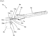
Fig 1 ] Lafigure 1 est une vue en perspective d'un récipient de cuisson selon un premier mode particulier de réalisation de l'invention, - [
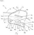
Fig 2 ] Lafigure 2 est une vue en perspective du récipient de cuisson de lafigure 1 , notamment de la pièce de liaison rivetée munie d'un bossage, - [
Fig 3 ] Lafigure 3 est une vue en coupe partielle suivant le plan de coupe horizontal fractionné III-III du récipient de cuisson de lafigure 2 , - [
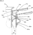
Fig 4 ] Lafigure 4 est une vue en coupe partielle suivant le plan de coupe vertical IV-IV du récipient de cuisson de lafigure 2 , le récipient de cuisson étant inséré dans un récipient de cuisson plus grand, - [
Fig 5 ] Lafigure 5 est une vue en perspective d'un récipient de cuisson selon un deuxième mode particulier de réalisation de l'invention, notamment de la pièce de liaison rivetée munie d'un bossage, - [
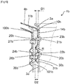
Fig 6 ] Lafigure 6 est une vue en coupe partielle suivant le plan de coupe vertical VI-VI du récipient de cuisson de lafigure 5 . - [
Fig 7 ] Lafigure 7 est une vue en perspective d'un récipient de cuisson selon une variante de réalisation du deuxième mode particulier de réalisation de l'invention, notamment de la pièce de liaison rivetée munie d'un bossage. - Seuls les éléments nécessaires à la compréhension de l'invention ont été représentés. Pour faciliter la lecture des dessins, les mêmes éléments portent les mêmes références d'une figure à l'autre.
- On notera que dans ce document, les termes "horizontal", "vertical", "inférieur", "supérieur", "haut", "bas", "avant", "arrière", "longitudinal", "transversal", employés pour décrire le récipient de cuisson font référence à ce récipient de cuisson en situation d'usage, lorsqu'il repose à plat sur un plan de travail ou un appareil de chauffage.
- Dans un premier mode de réalisation représenté aux
figures 1 à 4 , un récipient de cuisson 1a qui est une casserole comporte une calotte 2a munie d'une paroi latérale 3a et une poignée 4a. La poignée 4a comporte une partie de préhension 5a et une pièce de liaison 10a. La pièce de liaison 10a est fixée sur la paroi latérale 3. La partie de préhension 5a est agencée sur la pièce de liaison 10a de manière amovible. La pièce de liaison 10a comporte une portion radiale 11a qui s'étend radialement par rapport à la paroi latérale 3a dans un plan sensiblement horizontal, parallèle au plan de pose de la calotte 2a pour former une extrémité libre 12a. La portion radiale 11a comporte une ouverture 13a sensiblement rectangulaire. La poignée 4a s'étend selon un axe longitudinal et la partie de préhension 5a comprend à une extrémité un bec 6a à double cambrage (Fig 1 ) destiné à coopérer avec l'ouverture 13a pour assembler ou désassembler la partie de préhension 5a de la pièce de liaison 10a. La partie de préhension 5a comprend un verrou 7a mobile en translation suivant l'axe longitudinal. Le verrou 7a est mobile entre une position d'accouplement dans laquelle la partie de préhension 5a est assemblée sur la pièce de liaison 10a (Fig 1 ) et une position de désaccouplement (non illustrée sur les figures) dans laquelle la partie de préhension 5a peut être désassemblée de la pièce de liaison 10a. Le verrou 7a comporte une extrémité avant qui est glissée sous une face inférieure de la pièce de liaison 10a dans la position d'accouplement. Un bouton de manœuvre 8a est agencé sur la partie de préhension 5a et est fixé sur le verrou 7a pour permettre la commande du verrou 7a. Un récipient de cuisson muni d'une telle poignée a été décrit plus en détail, notamment dans le documentEP3569119 . - La pièce de liaison 10a comporte une portion axiale 14a qui s'étend parallèlement à la paroi latérale 3a de manière sensiblement verticale. La portion axiale 14a de la pièce de liaison 10a est fixée à la paroi latérale 3a par deux rivets 20a, 21a agencé dans un plan horizontal H1 (
Fig 2 ). Chaque rivet 20a, 21a comporte une tête 22a, 23a agencée à l'intérieur de la calotte 2 du récipient de cuisson 1a (Fig 3 ) et un bouterollage 24a, 25a qui s'étend vers l'extérieur de la calotte 2 du récipient de cuisson 1a, radialement à la paroi latérale 3. Le bouterollage 24a, 25a comporte une extrémité libre 26a, 27a qui est agencée à une distance D1 (Fig 3 ) de la paroi latérale 3a, la distance D1 étant égale à 4 millimètres. Le bouterollage 24a, 25a est le résultat de l'opération de sertissage de l'extrémité libre du rivet 20a, 21a, opposé à la tête 22a, 23a, à l'aide d'une bouterolle, une fois le rivet 20a, 21a assemblé sur la calotte 2 et la pièce de liaison 10a. Le bouterollage 24a, 25a prend une forme de demi-sphère. - La portion axiale 14a de la pièce de liaison 10a comporte un bossage 30a de forme oblongue qui s'étend dans un plan horizontal H2 (
Fig 2 ). Le bossage 30a comporte une extrémité libre arrondie 31a qui s'étend radialement à partir de la paroi latérale 2 sur une distance D2 égale à 10 millimètres. Dans un plan de coupe horizontal (Fig 3 ), l'extrémité libre arrondie 31a comporte une portion centrale 32a et deux portions latérales 33a, 34a.Sur lesfigures 2 et3 , la portion centrale 32a et les deux portions latérales 33a, 34a sont séparées par un trait mixte. La portion centrale 32a présente une forme de demi-cylindre d'axe légèrement incurvé et de rayon R égal à 10 millimètres. Les deux portions latérales 33a, 34a présentent une forme de quart de sphère de rayon R. Ainsi, l'extrémité libre arrondie 31a comporte une ligne de crête formé par des points équidistants de la paroi latérale 2a, parallèle à l'axe légèrement incurvé de la forme de demi-cylindre. L'extrémité libre arrondie 31a, notamment la ligne de crête, est agencée dans le plan horizontal H2, au-dessus du plan horizontal H1 et séparé du plan horizontal H1 par une distance égale à 1 millimètre. - La pièce de liaison 10a est réalisée à partir d'un feuillard métallique en acier inoxydable d'épaisseur égale à 3 millimètres. Le feuillard métallique est produit pour présenter au moins une face avec une finition de type poli brillant ou poli miroir. Le feuillard subit des opérations de découpe, pliage et emboutissage du bossage. L'extrémité libre 31a arrondie comporte une face externe 35a réalisée à partir de l'au moins une face avec une finition de type poli brillant ou poli miroir du feuillard. La face externe 35a de l'extrémité libre arrondie 31a est destinée à venir en appui avant l'extrémité libre 26a, 27a du bouterollage 24a, 25a sur une surface interne 101a d'un récipient de cuisson 100a plus grand lorsque le récipient de cuisson 1a est rangé par empilage dans le récipient de cuisson plus grand 100a (
Fig 4 ). - Dans un deuxième mode de réalisation illustré au
figures 5 et6 , un récipient de cuisson 1b qui est également une casserole comporte une calotte 2b munie d'une paroi latérale 3b. Le récipient de cuisson 1b comporte une poignée 4b munie d'une pièce de liaison 10b. La pièce de liaison 10b comporte une portion radiale 11b qui s'étend radialement par rapport à la paroi latérale 5b dans un plan sensiblement horizontal, parallèle au plan de pose de la calotte 2b. La poignée 4b comporte une partie de préhension 5b qui est surmoulée sur la portion radiale 11b de la pièce de liaison 10b. La pièce de liaison 10b est fixée sur la paroi latérale 3b. La pièce de liaison 10b comporte une portion axiale 14b qui s'étend parallèlement à la paroi latérale 3b de manière sensiblement verticale. La portion axiale 14b de la pièce de liaison 10b est fixée à la paroi latérale 3b par deux rivets 20b, 21b agencé dans un plan vertical, l'un au-dessus de l'autre. Chaque rivet 20b, 21b comporte une tête 22b, 23b agencée à l'intérieur de la calotte 2b du récipient de cuisson 1b (Fig 6 ) et un bouterollage 24b, 25b qui s'étend vers l'extérieur de la calotte 2b du récipient de cuisson 1b, radialement à la paroi latérale 3b. Le bouterollage 24b, 25b comporte une extrémité libre 26b, 27b qui est agencée à une distance D1 de la paroi latérale 3b, la distance D1 étant égale à 3 millimètres - La portion axiale 14b de la pièce de liaison 10b comporte un bossage 30b de forme annulaire, sensiblement circulaire qui s'étend autour du rivet 20b agencé à une altitude la plus basse. Le bossage 30b comporte une extrémité libre arrondie 31b qui s'étend radialement à partir de la paroi latérale 3b sur une distance D2 égale à 5 millimètres. Dans un plan de coupe transversal (
Fig 6 ), l'extrémité libre arrondie 31b présente une forme de V à pointe arrondie. L'extrémité libre arrondie 31b comporte un rayon R égal à 3 millimètres. Ainsi, l'extrémité libre arrondie 31b comporte une ligne de crête sensiblement circulaire, formée par des points équidistants de la paroi latérale 3b. L'extrémité libre arrondie 31b est destinée à venir en appui avant l'extrémité libre 26b, 27b du bouterollage 24b, 25b sur une surface interne 101b d'un récipient de cuisson 100b plus grand lorsque le récipient de cuisson 1b est rangé par empilage dans le récipient de cuisson 100b plus grand (Fig 6 ). - La pièce de liaison 10b est réalisée à partir d'un feuillard métallique de la même manière que la pièce de liaison 10a.
- Dans une variante du deuxième mode de réalisation illustré à la
figure 7 , le récipient de cuisson 1b comporte une pièce de liaison 10c munie d'une portion axiale14c. La portion axiale 14c comporte un bossage 30c en forme de U qui entoure partiellement les deux rivets 20b, 21b. La portion axiale 14c comporte un bord inférieur 15c et deux bords latéraux 16c, 17c. Le bossage 30c en forme de U s'étend le long du bord inférieur 15c et des deux bords latéraux 16c, 17c. Le bossage 30c est muni d'une extrémité libre arrondie 31c, qui dans un plan de coupe transversal, présente comme dans le deuxième mode de réalisation une forme de V à pointe arrondie. Un tel agencement du bossage 30c, notamment le long des bords latéraux 16c, 17c garantit que l'extrémité libre arrondie 31c viendra toujours en appui avant l'extrémité libre 26b, 27b du bouterollage 24b, 25b sur une surface interne 101b d'un récipient de cuisson 100b plus grand lorsque le récipient de cuisson 1b est rangé par empilage dans le récipient de cuisson 100b plus grand - Bien entendu, l'invention n'est nullement limitée au mode de réalisation décrit et illustré qui n'a été donné qu'à titre d'exemple. Des modifications restent possibles, notamment du point de vue de la constitution des divers éléments ou par substitution d'équivalents techniques, sans sortir pour autant du domaine de protection de l'invention.
- Ainsi, dans une variante de réalisation non représentée du premier mode de réalisation, la portion axiale 14a de la pièce de liaison 10a comporte un bossage qui entoure les deux rivets 20a, 21a. Le bossage comporte une extrémité libre arrondie de forme annulaire, sensiblement oblongue.
Claims (11)
- Récipient de cuisson (1a, 1b) comportant une paroi latérale (3a, 3b) et une poignée (4a, 4b), ladite poignée (4a, 4b) comprenant une pièce de liaison (10a, 10b, 10c) fixée sur la paroi latérale (3a, 3b) par des rivets (20a, 21a, 20b, 21b), chaque rivet (20a, 21a, 20b, 21b) comportant un bouterollage (24a, 25a, 24b, 25b) qui s'étend vers l'extérieur du récipient de cuisson (1a, 1b), radialement à la paroi latérale (3a, 3b), ledit bouterollage (24a, 25a, 24b, 25b) comportant une extrémité libre (26a, 27a, 26b, 27b) qui est agencée à une distance D1 de la paroi latérale (3a, 3b), caractérisé en ce que la pièce de liaison (10a, 10b, 10c) comporte au moins un bossage (30a, 30b, 30c) qui s'étend radialement à la paroi latérale (3a, 3b), ledit au moins un bossage (30a, 30b, 30c) comprenant une extrémité libre arrondie (31a, 31b, 31c) qui est agencée à une distance D2 de la paroi latérale (3a, 3b), la distance D2 étant supérieure à la distance D1 et en ce que l'extrémité libre arrondie (31a, 31b, 31c) de l'au moins un bossage (30a, 30b, 30c) est destinée à venir en appui avant l'extrémité libre (26a, 27a, 26b, 27b) du bouterollage (24a, 25a, 24b, 25b) sur une surface interne d'un récipient de cuisson plus grand lorsque le récipient de cuisson (1a, 1b) est rangé par empilage dans le récipient de cuisson plus grand, l'extrémité libre arrondie (31a, 31b, 31c) présentant une forme non agressive qui ne dégrade pas la surface interne du récipient de cuisson plus grand en cas de chocs ou de mouvements relatifs entre les récipients de cuisson.
- Récipient de cuisson (1a, 1b) selon la revendication 1, caractérisé en ce que la différence entre la distance D2 et la distance D1 est supérieure à 1 millimètre, de préférence supérieure à 2 millimètres.
- Récipient de cuisson (1a, 1b) selon l'une quelconque des revendications 1 à 2, caractérisé en ce que la pièce de liaison (10a, 10b, 10c) est réalisée en un acier inoxydable présentant une finition polie au niveau de l'extrémité libre arrondie (31a, 31b, 31c).
- Récipient de cuisson (1a) selon l'une quelconque des revendications 1 à 3, caractérisé en ce que la pièce de liaison (10a) est fixée sur la paroi latérale par deux rivets (20a, 21a), l'au moins un bossage (30a) étant agencé entre les deux rivets (20a, 21a).
- Récipient de cuisson (1a) selon la revendication 4, caractérisé en ce que les deux rivets (20a, 21a) sont agencés dans un plan horizontal H1 et le bossage (30a) est agencé dans un plan horizontal H2, Le plan horizontal H1 étant séparé du plan horizontal H2 par une distance inférieure à 10 millimètres.
- Récipient de cuisson (1b) selon l'une quelconque des revendications 1 à 3, caractérisé en ce que l'au moins un bossage (30b, 30c) entoure au moins partiellement au moins un rivet (20b, 21b).
- Récipient de cuisson (1b) selon la revendication 6, caractérisé en ce que l'au moins un bossage (30b) présente une forme annulaire qui entoure au moins un rivet (20b).
- Récipient de cuisson (1a, 1b) selon l'une quelconque des revendications 1 à 7, caractérisé en ce que l'extrémité libre arrondie (31a, 31b, 31c) de l'au moins un bossage (30a, 30b, 30c) comporte un rayon R supérieur à 2 millimètres.
- Récipient de cuisson (1a) selon l'une quelconque des revendications 1 à 8, caractérisé en ce que la poignée (4a) comporte une partie de préhension (5a) agencée sur la pièce de liaison (10a) de manière amovible.
- Récipient de cuisson (1a, 1b) selon l'une quelconque des revendications 1 à 9, caractérisé en ce qu'il est une poêle, une casserole, une sauteuse ou un faitout.
- Récipient de cuisson (1a, 1b) selon l'une quelconque des revendications 1 à 10, caractérisé en ce que la pièce de liaison (10a, 10b, 10c) est réalisée à partir d'un feuillard métallique, le bossage (30a, 30b, 30c) étant réalisé par une opération d'emboutissage.
Applications Claiming Priority (1)
| Application Number | Priority Date | Filing Date | Title |
|---|---|---|---|
| FR2102949A FR3121024B1 (fr) | 2021-03-24 | 2021-03-24 | Recipient de cuisson muni d’une poignee rivetee amelioree. |
Publications (2)
| Publication Number | Publication Date |
|---|---|
| EP4062813A1 true EP4062813A1 (fr) | 2022-09-28 |
| EP4062813B1 EP4062813B1 (fr) | 2023-11-08 |
Family
ID=76159528
Family Applications (1)
| Application Number | Title | Priority Date | Filing Date |
|---|---|---|---|
| EP22162719.3A Active EP4062813B1 (fr) | 2021-03-24 | 2022-03-17 | Récipient de cuisson muni d'une poignée rivetée ameliorée |
Country Status (3)
| Country | Link |
|---|---|
| EP (1) | EP4062813B1 (fr) |
| CN (1) | CN115120118A (fr) |
| FR (1) | FR3121024B1 (fr) |
Citations (4)
| Publication number | Priority date | Publication date | Assignee | Title |
|---|---|---|---|---|
| FR1258876A (fr) | 1960-03-07 | 1961-04-21 | Tefal Sa | Dispositif de liaison démontable entre un ustensile et un organe de préhension |
| US4724576A (en) * | 1986-05-27 | 1988-02-16 | Nitto Aluminium Mfg. Co., Ltd. | Handle of a pot |
| US20150114973A1 (en) | 2013-10-30 | 2015-04-30 | Tramontina Usa, Inc. | Fusion rivet cooking apparatus and method |
| EP3569119A1 (fr) | 2018-05-18 | 2019-11-20 | Seb S.A. | Ensemble formé par un récipient de cuisson muni d´une anse et une poignée amovible |
Family Cites Families (5)
| Publication number | Priority date | Publication date | Assignee | Title |
|---|---|---|---|---|
| KR20100095892A (ko) * | 2009-02-23 | 2010-09-01 | 조난기 | 탈부착이 용이한 조리기구 손잡이 |
| FR2962320B1 (fr) * | 2010-07-06 | 2012-07-20 | Seb Sa | Article culinaire avec organe de prehension rabattable |
| EP3491979A1 (fr) * | 2017-11-29 | 2019-06-05 | LAGOSTINA S.p.A. | Récipient de cuisson, notamment de pates |
| CN209202782U (zh) * | 2018-09-17 | 2019-08-06 | 浙江苏泊尔股份有限公司 | 可叠的滤水锅及烹饪器具 |
| CN210870997U (zh) * | 2019-08-02 | 2020-06-30 | 新兴县先丰不锈钢制品有限公司 | 一种具有堆叠功能的倒水锅 |
-
2021
- 2021-03-24 FR FR2102949A patent/FR3121024B1/fr active Active
-
2022
- 2022-03-17 EP EP22162719.3A patent/EP4062813B1/fr active Active
- 2022-03-17 CN CN202210264536.9A patent/CN115120118A/zh active Pending
Patent Citations (4)
| Publication number | Priority date | Publication date | Assignee | Title |
|---|---|---|---|---|
| FR1258876A (fr) | 1960-03-07 | 1961-04-21 | Tefal Sa | Dispositif de liaison démontable entre un ustensile et un organe de préhension |
| US4724576A (en) * | 1986-05-27 | 1988-02-16 | Nitto Aluminium Mfg. Co., Ltd. | Handle of a pot |
| US20150114973A1 (en) | 2013-10-30 | 2015-04-30 | Tramontina Usa, Inc. | Fusion rivet cooking apparatus and method |
| EP3569119A1 (fr) | 2018-05-18 | 2019-11-20 | Seb S.A. | Ensemble formé par un récipient de cuisson muni d´une anse et une poignée amovible |
Also Published As
| Publication number | Publication date |
|---|---|
| FR3121024B1 (fr) | 2023-06-30 |
| EP4062813B1 (fr) | 2023-11-08 |
| CN115120118A (zh) | 2022-09-30 |
| FR3121024A1 (fr) | 2022-09-30 |
Similar Documents
| Publication | Publication Date | Title |
|---|---|---|
| EP2243408B1 (fr) | Dispositif de préhension amovible d'un récipient culinaire et récipient culinaire pourvu d'un tel dispositif | |
| EP1800581B1 (fr) | Recipient de cuisine avec au moins un moyen de prehension pivotant | |
| EP3319497B1 (fr) | Poignée amovible | |
| EP4026463B1 (fr) | Poignee amovible presentant un assemblage optimise | |
| EP2404537B1 (fr) | Article culinaire avec organe de préhension rabattable | |
| EP3469970A1 (fr) | Porte-lame pour robot ménager de cuisine | |
| EP3569119B1 (fr) | Ensemble formé par un récipient de cuisson muni d´une anse et une poignée amovible | |
| EP4026462B1 (fr) | Poignée amovible munie d'un organe d'appui renforce | |
| EP4062813B1 (fr) | Récipient de cuisson muni d'une poignée rivetée ameliorée | |
| EP4312685B1 (fr) | Recipient de cuisson muni d'une poignee fixee par deux rivets superposes | |
| EP4159097A1 (fr) | Ensemble formé par un récipient de cuisson muni d'une anse et une poignée amovible | |
| WO2024208755A1 (fr) | Recipient de cuisson muni d'une poignee fixee par deux rivets affleurants | |
| EP2665399B1 (fr) | Dispositif amovible de préhension d'un ustensile de cuisson | |
| EP0852924B1 (fr) | Dispositif de préhension pour ustensile de cuisson | |
| EP0810838A1 (fr) | Ustensile de cuisson a anse annulaire | |
| EP4431753B1 (fr) | Dispositif de fixation par vissage muni d'un cache vis | |
| EP1174064B1 (fr) | Couvercle de cocotte ou analogue | |
| FR2579444A1 (fr) | Dispositif de prehension pour article culinaire | |
| EP3062671B1 (fr) | Article culinaire comportant une anse rabattable | |
| FR3052966A1 (fr) | Couvercle de recipient de cuisson muni d'un bec verseur | |
| FR2832046A1 (fr) | Couvercle de cocotte ou faitout ou analogue muni d'un dispositif de solidarisation avec le corps de la cocotte ou faitout | |
| EP1949832A1 (fr) | Outil rotatif amovible avec organe de préhension amélioré |
Legal Events
| Date | Code | Title | Description |
|---|---|---|---|
| PUAI | Public reference made under article 153(3) epc to a published international application that has entered the european phase |
Free format text: ORIGINAL CODE: 0009012 |
|
| STAA | Information on the status of an ep patent application or granted ep patent |
Free format text: STATUS: THE APPLICATION HAS BEEN PUBLISHED |
|
| AK | Designated contracting states |
Kind code of ref document: A1 Designated state(s): AL AT BE BG CH CY CZ DE DK EE ES FI FR GB GR HR HU IE IS IT LI LT LU LV MC MK MT NL NO PL PT RO RS SE SI SK SM TR |
|
| STAA | Information on the status of an ep patent application or granted ep patent |
Free format text: STATUS: REQUEST FOR EXAMINATION WAS MADE |
|
| 17P | Request for examination filed |
Effective date: 20230309 |
|
| RBV | Designated contracting states (corrected) |
Designated state(s): AL AT BE BG CH CY CZ DE DK EE ES FI FR GB GR HR HU IE IS IT LI LT LU LV MC MK MT NL NO PL PT RO RS SE SI SK SM TR |
|
| GRAP | Despatch of communication of intention to grant a patent |
Free format text: ORIGINAL CODE: EPIDOSNIGR1 |
|
| STAA | Information on the status of an ep patent application or granted ep patent |
Free format text: STATUS: GRANT OF PATENT IS INTENDED |
|
| RIC1 | Information provided on ipc code assigned before grant |
Ipc: A47J 45/07 20060101ALI20230512BHEP Ipc: A47J 45/06 20060101AFI20230512BHEP |
|
| INTG | Intention to grant announced |
Effective date: 20230601 |
|
| GRAS | Grant fee paid |
Free format text: ORIGINAL CODE: EPIDOSNIGR3 |
|
| GRAA | (expected) grant |
Free format text: ORIGINAL CODE: 0009210 |
|
| STAA | Information on the status of an ep patent application or granted ep patent |
Free format text: STATUS: THE PATENT HAS BEEN GRANTED |
|
| AK | Designated contracting states |
Kind code of ref document: B1 Designated state(s): AL AT BE BG CH CY CZ DE DK EE ES FI FR GB GR HR HU IE IS IT LI LT LU LV MC MK MT NL NO PL PT RO RS SE SI SK SM TR |
|
| REG | Reference to a national code |
Ref country code: GB Ref legal event code: FG4D Free format text: NOT ENGLISH |
|
| REG | Reference to a national code |
Ref country code: CH Ref legal event code: EP |
|
| REG | Reference to a national code |
Ref country code: DE Ref legal event code: R096 Ref document number: 602022000899 Country of ref document: DE |
|
| REG | Reference to a national code |
Ref country code: IE Ref legal event code: FG4D Free format text: LANGUAGE OF EP DOCUMENT: FRENCH |
|
| REG | Reference to a national code |
Ref country code: LT Ref legal event code: MG9D |
|
| REG | Reference to a national code |
Ref country code: NL Ref legal event code: MP Effective date: 20231108 |
|
| PG25 | Lapsed in a contracting state [announced via postgrant information from national office to epo] |
Ref country code: GR Free format text: LAPSE BECAUSE OF FAILURE TO SUBMIT A TRANSLATION OF THE DESCRIPTION OR TO PAY THE FEE WITHIN THE PRESCRIBED TIME-LIMIT Effective date: 20240209 |
|
| PG25 | Lapsed in a contracting state [announced via postgrant information from national office to epo] |
Ref country code: IS Free format text: LAPSE BECAUSE OF FAILURE TO SUBMIT A TRANSLATION OF THE DESCRIPTION OR TO PAY THE FEE WITHIN THE PRESCRIBED TIME-LIMIT Effective date: 20240308 |
|
| PG25 | Lapsed in a contracting state [announced via postgrant information from national office to epo] |
Ref country code: LT Free format text: LAPSE BECAUSE OF FAILURE TO SUBMIT A TRANSLATION OF THE DESCRIPTION OR TO PAY THE FEE WITHIN THE PRESCRIBED TIME-LIMIT Effective date: 20231108 |
|
| REG | Reference to a national code |
Ref country code: AT Ref legal event code: MK05 Ref document number: 1628851 Country of ref document: AT Kind code of ref document: T Effective date: 20231108 |
|
| PG25 | Lapsed in a contracting state [announced via postgrant information from national office to epo] |
Ref country code: NL Free format text: LAPSE BECAUSE OF FAILURE TO SUBMIT A TRANSLATION OF THE DESCRIPTION OR TO PAY THE FEE WITHIN THE PRESCRIBED TIME-LIMIT Effective date: 20231108 |
|
| PG25 | Lapsed in a contracting state [announced via postgrant information from national office to epo] |
Ref country code: AT Free format text: LAPSE BECAUSE OF FAILURE TO SUBMIT A TRANSLATION OF THE DESCRIPTION OR TO PAY THE FEE WITHIN THE PRESCRIBED TIME-LIMIT Effective date: 20231108 |
|
| PG25 | Lapsed in a contracting state [announced via postgrant information from national office to epo] |
Ref country code: ES Free format text: LAPSE BECAUSE OF FAILURE TO SUBMIT A TRANSLATION OF THE DESCRIPTION OR TO PAY THE FEE WITHIN THE PRESCRIBED TIME-LIMIT Effective date: 20231108 |
|
| PG25 | Lapsed in a contracting state [announced via postgrant information from national office to epo] |
Ref country code: NL Free format text: LAPSE BECAUSE OF FAILURE TO SUBMIT A TRANSLATION OF THE DESCRIPTION OR TO PAY THE FEE WITHIN THE PRESCRIBED TIME-LIMIT Effective date: 20231108 Ref country code: LT Free format text: LAPSE BECAUSE OF FAILURE TO SUBMIT A TRANSLATION OF THE DESCRIPTION OR TO PAY THE FEE WITHIN THE PRESCRIBED TIME-LIMIT Effective date: 20231108 Ref country code: IS Free format text: LAPSE BECAUSE OF FAILURE TO SUBMIT A TRANSLATION OF THE DESCRIPTION OR TO PAY THE FEE WITHIN THE PRESCRIBED TIME-LIMIT Effective date: 20240308 Ref country code: GR Free format text: LAPSE BECAUSE OF FAILURE TO SUBMIT A TRANSLATION OF THE DESCRIPTION OR TO PAY THE FEE WITHIN THE PRESCRIBED TIME-LIMIT Effective date: 20240209 Ref country code: ES Free format text: LAPSE BECAUSE OF FAILURE TO SUBMIT A TRANSLATION OF THE DESCRIPTION OR TO PAY THE FEE WITHIN THE PRESCRIBED TIME-LIMIT Effective date: 20231108 Ref country code: BG Free format text: LAPSE BECAUSE OF FAILURE TO SUBMIT A TRANSLATION OF THE DESCRIPTION OR TO PAY THE FEE WITHIN THE PRESCRIBED TIME-LIMIT Effective date: 20240208 Ref country code: AT Free format text: LAPSE BECAUSE OF FAILURE TO SUBMIT A TRANSLATION OF THE DESCRIPTION OR TO PAY THE FEE WITHIN THE PRESCRIBED TIME-LIMIT Effective date: 20231108 Ref country code: PT Free format text: LAPSE BECAUSE OF FAILURE TO SUBMIT A TRANSLATION OF THE DESCRIPTION OR TO PAY THE FEE WITHIN THE PRESCRIBED TIME-LIMIT Effective date: 20240308 |
|
| PG25 | Lapsed in a contracting state [announced via postgrant information from national office to epo] |
Ref country code: SE Free format text: LAPSE BECAUSE OF FAILURE TO SUBMIT A TRANSLATION OF THE DESCRIPTION OR TO PAY THE FEE WITHIN THE PRESCRIBED TIME-LIMIT Effective date: 20231108 Ref country code: RS Free format text: LAPSE BECAUSE OF FAILURE TO SUBMIT A TRANSLATION OF THE DESCRIPTION OR TO PAY THE FEE WITHIN THE PRESCRIBED TIME-LIMIT Effective date: 20231108 Ref country code: PL Free format text: LAPSE BECAUSE OF FAILURE TO SUBMIT A TRANSLATION OF THE DESCRIPTION OR TO PAY THE FEE WITHIN THE PRESCRIBED TIME-LIMIT Effective date: 20231108 Ref country code: NO Free format text: LAPSE BECAUSE OF FAILURE TO SUBMIT A TRANSLATION OF THE DESCRIPTION OR TO PAY THE FEE WITHIN THE PRESCRIBED TIME-LIMIT Effective date: 20240208 Ref country code: LV Free format text: LAPSE BECAUSE OF FAILURE TO SUBMIT A TRANSLATION OF THE DESCRIPTION OR TO PAY THE FEE WITHIN THE PRESCRIBED TIME-LIMIT Effective date: 20231108 Ref country code: HR Free format text: LAPSE BECAUSE OF FAILURE TO SUBMIT A TRANSLATION OF THE DESCRIPTION OR TO PAY THE FEE WITHIN THE PRESCRIBED TIME-LIMIT Effective date: 20231108 |
|
| PG25 | Lapsed in a contracting state [announced via postgrant information from national office to epo] |
Ref country code: DK Free format text: LAPSE BECAUSE OF FAILURE TO SUBMIT A TRANSLATION OF THE DESCRIPTION OR TO PAY THE FEE WITHIN THE PRESCRIBED TIME-LIMIT Effective date: 20231108 |
|
| PG25 | Lapsed in a contracting state [announced via postgrant information from national office to epo] |
Ref country code: CZ Free format text: LAPSE BECAUSE OF FAILURE TO SUBMIT A TRANSLATION OF THE DESCRIPTION OR TO PAY THE FEE WITHIN THE PRESCRIBED TIME-LIMIT Effective date: 20231108 |
|
| PG25 | Lapsed in a contracting state [announced via postgrant information from national office to epo] |
Ref country code: SK Free format text: LAPSE BECAUSE OF FAILURE TO SUBMIT A TRANSLATION OF THE DESCRIPTION OR TO PAY THE FEE WITHIN THE PRESCRIBED TIME-LIMIT Effective date: 20231108 |
|
| PG25 | Lapsed in a contracting state [announced via postgrant information from national office to epo] |
Ref country code: SM Free format text: LAPSE BECAUSE OF FAILURE TO SUBMIT A TRANSLATION OF THE DESCRIPTION OR TO PAY THE FEE WITHIN THE PRESCRIBED TIME-LIMIT Effective date: 20231108 Ref country code: SK Free format text: LAPSE BECAUSE OF FAILURE TO SUBMIT A TRANSLATION OF THE DESCRIPTION OR TO PAY THE FEE WITHIN THE PRESCRIBED TIME-LIMIT Effective date: 20231108 Ref country code: RO Free format text: LAPSE BECAUSE OF FAILURE TO SUBMIT A TRANSLATION OF THE DESCRIPTION OR TO PAY THE FEE WITHIN THE PRESCRIBED TIME-LIMIT Effective date: 20231108 Ref country code: IT Free format text: LAPSE BECAUSE OF FAILURE TO SUBMIT A TRANSLATION OF THE DESCRIPTION OR TO PAY THE FEE WITHIN THE PRESCRIBED TIME-LIMIT Effective date: 20231108 Ref country code: EE Free format text: LAPSE BECAUSE OF FAILURE TO SUBMIT A TRANSLATION OF THE DESCRIPTION OR TO PAY THE FEE WITHIN THE PRESCRIBED TIME-LIMIT Effective date: 20231108 Ref country code: DK Free format text: LAPSE BECAUSE OF FAILURE TO SUBMIT A TRANSLATION OF THE DESCRIPTION OR TO PAY THE FEE WITHIN THE PRESCRIBED TIME-LIMIT Effective date: 20231108 Ref country code: CZ Free format text: LAPSE BECAUSE OF FAILURE TO SUBMIT A TRANSLATION OF THE DESCRIPTION OR TO PAY THE FEE WITHIN THE PRESCRIBED TIME-LIMIT Effective date: 20231108 |
|
| REG | Reference to a national code |
Ref country code: DE Ref legal event code: R097 Ref document number: 602022000899 Country of ref document: DE |
|
| PLBE | No opposition filed within time limit |
Free format text: ORIGINAL CODE: 0009261 |
|
| STAA | Information on the status of an ep patent application or granted ep patent |
Free format text: STATUS: NO OPPOSITION FILED WITHIN TIME LIMIT |
|
| 26N | No opposition filed |
Effective date: 20240809 |
|
| PG25 | Lapsed in a contracting state [announced via postgrant information from national office to epo] |
Ref country code: SI Free format text: LAPSE BECAUSE OF FAILURE TO SUBMIT A TRANSLATION OF THE DESCRIPTION OR TO PAY THE FEE WITHIN THE PRESCRIBED TIME-LIMIT Effective date: 20231108 |
|
| PG25 | Lapsed in a contracting state [announced via postgrant information from national office to epo] |
Ref country code: SI Free format text: LAPSE BECAUSE OF FAILURE TO SUBMIT A TRANSLATION OF THE DESCRIPTION OR TO PAY THE FEE WITHIN THE PRESCRIBED TIME-LIMIT Effective date: 20231108 |
|
| PG25 | Lapsed in a contracting state [announced via postgrant information from national office to epo] |
Ref country code: LU Free format text: LAPSE BECAUSE OF NON-PAYMENT OF DUE FEES Effective date: 20240317 |
|
| PG25 | Lapsed in a contracting state [announced via postgrant information from national office to epo] |
Ref country code: MC Free format text: LAPSE BECAUSE OF FAILURE TO SUBMIT A TRANSLATION OF THE DESCRIPTION OR TO PAY THE FEE WITHIN THE PRESCRIBED TIME-LIMIT Effective date: 20231108 |
|
| PG25 | Lapsed in a contracting state [announced via postgrant information from national office to epo] |
Ref country code: MC Free format text: LAPSE BECAUSE OF FAILURE TO SUBMIT A TRANSLATION OF THE DESCRIPTION OR TO PAY THE FEE WITHIN THE PRESCRIBED TIME-LIMIT Effective date: 20231108 Ref country code: LU Free format text: LAPSE BECAUSE OF NON-PAYMENT OF DUE FEES Effective date: 20240317 |
|
| REG | Reference to a national code |
Ref country code: BE Ref legal event code: MM Effective date: 20240331 |
|
| PG25 | Lapsed in a contracting state [announced via postgrant information from national office to epo] |
Ref country code: BE Free format text: LAPSE BECAUSE OF NON-PAYMENT OF DUE FEES Effective date: 20240331 |
|
| PG25 | Lapsed in a contracting state [announced via postgrant information from national office to epo] |
Ref country code: IE Free format text: LAPSE BECAUSE OF NON-PAYMENT OF DUE FEES Effective date: 20240317 |
|
| PG25 | Lapsed in a contracting state [announced via postgrant information from national office to epo] |
Ref country code: IE Free format text: LAPSE BECAUSE OF NON-PAYMENT OF DUE FEES Effective date: 20240317 Ref country code: BE Free format text: LAPSE BECAUSE OF NON-PAYMENT OF DUE FEES Effective date: 20240331 |
|
| PGFP | Annual fee paid to national office [announced via postgrant information from national office to epo] |
Ref country code: DE Payment date: 20250313 Year of fee payment: 4 |
|
| PGFP | Annual fee paid to national office [announced via postgrant information from national office to epo] |
Ref country code: FR Payment date: 20250331 Year of fee payment: 4 |
|
| PG25 | Lapsed in a contracting state [announced via postgrant information from national office to epo] |
Ref country code: CY Free format text: LAPSE BECAUSE OF FAILURE TO SUBMIT A TRANSLATION OF THE DESCRIPTION OR TO PAY THE FEE WITHIN THE PRESCRIBED TIME-LIMIT; INVALID AB INITIO Effective date: 20220317 |
|
| PG25 | Lapsed in a contracting state [announced via postgrant information from national office to epo] |
Ref country code: FI Free format text: LAPSE BECAUSE OF FAILURE TO SUBMIT A TRANSLATION OF THE DESCRIPTION OR TO PAY THE FEE WITHIN THE PRESCRIBED TIME-LIMIT Effective date: 20231108 |
|
| REG | Reference to a national code |
Ref country code: CH Ref legal event code: H13 Free format text: ST27 STATUS EVENT CODE: U-0-0-H10-H13 (AS PROVIDED BY THE NATIONAL OFFICE) Effective date: 20251023 |
|
| PG25 | Lapsed in a contracting state [announced via postgrant information from national office to epo] |
Ref country code: TR Free format text: LAPSE BECAUSE OF FAILURE TO SUBMIT A TRANSLATION OF THE DESCRIPTION OR TO PAY THE FEE WITHIN THE PRESCRIBED TIME-LIMIT Effective date: 20231108 |
|
| PG25 | Lapsed in a contracting state [announced via postgrant information from national office to epo] |
Ref country code: CH Free format text: LAPSE BECAUSE OF NON-PAYMENT OF DUE FEES Effective date: 20250331 |