EP4062780A1 - Gabarit pour usage avec élément de chauffage pour dispositif de génération d'aérosol - Google Patents
Gabarit pour usage avec élément de chauffage pour dispositif de génération d'aérosol Download PDFInfo
- Publication number
- EP4062780A1 EP4062780A1 EP21165276.3A EP21165276A EP4062780A1 EP 4062780 A1 EP4062780 A1 EP 4062780A1 EP 21165276 A EP21165276 A EP 21165276A EP 4062780 A1 EP4062780 A1 EP 4062780A1
- Authority
- EP
- European Patent Office
- Prior art keywords
- aerosol generating
- aerosol
- layer
- heating
- generating substrate
- Prior art date
- Legal status (The legal status is an assumption and is not a legal conclusion. Google has not performed a legal analysis and makes no representation as to the accuracy of the status listed.)
- Pending
Links
- 239000000443 aerosol Substances 0.000 title claims abstract description 252
- 238000010438 heat treatment Methods 0.000 title claims abstract description 201
- 239000000758 substrate Substances 0.000 title claims abstract description 137
- 239000010410 layer Substances 0.000 claims description 148
- QTBSBXVTEAMEQO-UHFFFAOYSA-M Acetate Chemical compound CC([O-])=O QTBSBXVTEAMEQO-UHFFFAOYSA-M 0.000 claims description 80
- 235000002637 Nicotiana tabacum Nutrition 0.000 claims description 79
- 241000208125 Nicotiana Species 0.000 claims description 78
- 239000000835 fiber Substances 0.000 claims description 74
- 239000002184 metal Substances 0.000 claims description 70
- 229910052751 metal Inorganic materials 0.000 claims description 63
- 230000000284 resting effect Effects 0.000 claims description 52
- 239000000463 material Substances 0.000 claims description 47
- 229910045601 alloy Inorganic materials 0.000 claims description 37
- 239000000956 alloy Substances 0.000 claims description 37
- 229910052782 aluminium Inorganic materials 0.000 claims description 36
- XAGFODPZIPBFFR-UHFFFAOYSA-N aluminium Chemical compound [Al] XAGFODPZIPBFFR-UHFFFAOYSA-N 0.000 claims description 36
- PXHVJJICTQNCMI-UHFFFAOYSA-N Nickel Chemical compound [Ni] PXHVJJICTQNCMI-UHFFFAOYSA-N 0.000 claims description 32
- 239000012792 core layer Substances 0.000 claims description 32
- 239000011127 biaxially oriented polypropylene Substances 0.000 claims description 30
- 229920006378 biaxially oriented polypropylene Polymers 0.000 claims description 29
- RYGMFSIKBFXOCR-UHFFFAOYSA-N Copper Chemical compound [Cu] RYGMFSIKBFXOCR-UHFFFAOYSA-N 0.000 claims description 28
- 239000004020 conductor Substances 0.000 claims description 26
- 239000010949 copper Substances 0.000 claims description 26
- 229910052802 copper Inorganic materials 0.000 claims description 26
- 239000000919 ceramic Substances 0.000 claims description 24
- 229920003023 plastic Polymers 0.000 claims description 24
- 239000004033 plastic Substances 0.000 claims description 24
- 229920000642 polymer Polymers 0.000 claims description 23
- 229910001092 metal group alloy Inorganic materials 0.000 claims description 21
- 229920000742 Cotton Polymers 0.000 claims description 19
- 239000004744 fabric Substances 0.000 claims description 19
- 239000011888 foil Substances 0.000 claims description 17
- 229910052759 nickel Inorganic materials 0.000 claims description 16
- 229910052709 silver Inorganic materials 0.000 claims description 16
- 239000004332 silver Substances 0.000 claims description 16
- 239000000843 powder Substances 0.000 claims description 15
- BQCADISMDOOEFD-UHFFFAOYSA-N Silver Chemical compound [Ag] BQCADISMDOOEFD-UHFFFAOYSA-N 0.000 claims description 14
- ATJFFYVFTNAWJD-UHFFFAOYSA-N Tin Chemical compound [Sn] ATJFFYVFTNAWJD-UHFFFAOYSA-N 0.000 claims description 14
- 239000011135 tin Substances 0.000 claims description 14
- 229910052718 tin Inorganic materials 0.000 claims description 14
- 239000004411 aluminium Substances 0.000 claims description 13
- 208000034530 PLAA-associated neurodevelopmental disease Diseases 0.000 claims description 12
- -1 polypropylene Polymers 0.000 claims description 11
- 239000004743 Polypropylene Substances 0.000 claims description 10
- 229920001155 polypropylene Polymers 0.000 claims description 10
- 230000017525 heat dissipation Effects 0.000 claims description 9
- 238000000034 method Methods 0.000 claims description 7
- 239000002356 single layer Substances 0.000 claims description 7
- 239000008187 granular material Substances 0.000 claims description 6
- 238000001125 extrusion Methods 0.000 claims description 5
- 239000011889 copper foil Substances 0.000 claims description 4
- 238000004512 die casting Methods 0.000 claims description 4
- 238000010146 3D printing Methods 0.000 claims description 3
- 229920003043 Cellulose fiber Polymers 0.000 claims description 3
- 238000001746 injection moulding Methods 0.000 claims description 3
- 238000005495 investment casting Methods 0.000 claims description 3
- 238000003754 machining Methods 0.000 claims description 3
- 238000001816 cooling Methods 0.000 claims description 2
- 230000002093 peripheral effect Effects 0.000 claims 2
- 229920002994 synthetic fiber Polymers 0.000 claims 1
- 239000000123 paper Substances 0.000 description 86
- DNIAPMSPPWPWGF-UHFFFAOYSA-N Propylene glycol Chemical compound CC(O)CO DNIAPMSPPWPWGF-UHFFFAOYSA-N 0.000 description 24
- 239000003610 charcoal Substances 0.000 description 16
- FYYHWMGAXLPEAU-UHFFFAOYSA-N Magnesium Chemical compound [Mg] FYYHWMGAXLPEAU-UHFFFAOYSA-N 0.000 description 7
- 239000011777 magnesium Substances 0.000 description 7
- 229910052749 magnesium Inorganic materials 0.000 description 7
- 239000004626 polylactic acid Substances 0.000 description 7
- 239000010935 stainless steel Substances 0.000 description 7
- 229910001220 stainless steel Inorganic materials 0.000 description 7
- PEDCQBHIVMGVHV-UHFFFAOYSA-N Glycerine Chemical compound OCC(O)CO PEDCQBHIVMGVHV-UHFFFAOYSA-N 0.000 description 6
- 229920000747 poly(lactic acid) Polymers 0.000 description 6
- WPPDFTBPZNZZRP-UHFFFAOYSA-N aluminum copper Chemical compound [Al].[Cu] WPPDFTBPZNZZRP-UHFFFAOYSA-N 0.000 description 5
- 238000000576 coating method Methods 0.000 description 5
- 238000004049 embossing Methods 0.000 description 5
- 230000007246 mechanism Effects 0.000 description 5
- 229910000838 Al alloy Inorganic materials 0.000 description 4
- 239000011248 coating agent Substances 0.000 description 4
- 238000002788 crimping Methods 0.000 description 4
- 238000009413 insulation Methods 0.000 description 4
- 238000002485 combustion reaction Methods 0.000 description 3
- 230000007717 exclusion Effects 0.000 description 3
- 235000011187 glycerol Nutrition 0.000 description 3
- 238000004519 manufacturing process Methods 0.000 description 3
- 239000008188 pellet Substances 0.000 description 3
- XEEYBQQBJWHFJM-UHFFFAOYSA-N Iron Chemical compound [Fe] XEEYBQQBJWHFJM-UHFFFAOYSA-N 0.000 description 2
- PNEYBMLMFCGWSK-UHFFFAOYSA-N aluminium oxide Inorganic materials [O-2].[O-2].[O-2].[Al+3].[Al+3] PNEYBMLMFCGWSK-UHFFFAOYSA-N 0.000 description 2
- 229910052799 carbon Inorganic materials 0.000 description 2
- 239000011521 glass Substances 0.000 description 2
- 239000004615 ingredient Substances 0.000 description 2
- 238000003780 insertion Methods 0.000 description 2
- 230000037431 insertion Effects 0.000 description 2
- 238000009740 moulding (composite fabrication) Methods 0.000 description 2
- 238000007747 plating Methods 0.000 description 2
- 238000005096 rolling process Methods 0.000 description 2
- 235000013311 vegetables Nutrition 0.000 description 2
- OKTJSMMVPCPJKN-UHFFFAOYSA-N Carbon Chemical compound [C] OKTJSMMVPCPJKN-UHFFFAOYSA-N 0.000 description 1
- HBBGRARXTFLTSG-UHFFFAOYSA-N Lithium ion Chemical compound [Li+] HBBGRARXTFLTSG-UHFFFAOYSA-N 0.000 description 1
- 244000061176 Nicotiana tabacum Species 0.000 description 1
- XUIMIQQOPSSXEZ-UHFFFAOYSA-N Silicon Chemical compound [Si] XUIMIQQOPSSXEZ-UHFFFAOYSA-N 0.000 description 1
- RTAQQCXQSZGOHL-UHFFFAOYSA-N Titanium Chemical compound [Ti] RTAQQCXQSZGOHL-UHFFFAOYSA-N 0.000 description 1
- HCHKCACWOHOZIP-UHFFFAOYSA-N Zinc Chemical compound [Zn] HCHKCACWOHOZIP-UHFFFAOYSA-N 0.000 description 1
- 238000010521 absorption reaction Methods 0.000 description 1
- 239000004964 aerogel Substances 0.000 description 1
- 230000032683 aging Effects 0.000 description 1
- 239000011230 binding agent Substances 0.000 description 1
- 239000002775 capsule Substances 0.000 description 1
- 239000002131 composite material Substances 0.000 description 1
- 230000000994 depressogenic effect Effects 0.000 description 1
- 238000001035 drying Methods 0.000 description 1
- 239000000428 dust Substances 0.000 description 1
- 239000000796 flavoring agent Substances 0.000 description 1
- 235000019634 flavors Nutrition 0.000 description 1
- 239000003365 glass fiber Substances 0.000 description 1
- 238000002347 injection Methods 0.000 description 1
- 239000007924 injection Substances 0.000 description 1
- 229910052742 iron Inorganic materials 0.000 description 1
- 229910001416 lithium ion Inorganic materials 0.000 description 1
- WPBNNNQJVZRUHP-UHFFFAOYSA-L manganese(2+);methyl n-[[2-(methoxycarbonylcarbamothioylamino)phenyl]carbamothioyl]carbamate;n-[2-(sulfidocarbothioylamino)ethyl]carbamodithioate Chemical compound [Mn+2].[S-]C(=S)NCCNC([S-])=S.COC(=O)NC(=S)NC1=CC=CC=C1NC(=S)NC(=O)OC WPBNNNQJVZRUHP-UHFFFAOYSA-L 0.000 description 1
- 150000002739 metals Chemical class 0.000 description 1
- 239000000203 mixture Substances 0.000 description 1
- 239000006187 pill Substances 0.000 description 1
- 238000003825 pressing Methods 0.000 description 1
- 229910052710 silicon Inorganic materials 0.000 description 1
- 239000010703 silicon Substances 0.000 description 1
- 239000010902 straw Substances 0.000 description 1
- 239000003826 tablet Substances 0.000 description 1
- 239000010936 titanium Substances 0.000 description 1
- 229910052719 titanium Inorganic materials 0.000 description 1
- 229910052720 vanadium Inorganic materials 0.000 description 1
- LEONUFNNVUYDNQ-UHFFFAOYSA-N vanadium atom Chemical compound [V] LEONUFNNVUYDNQ-UHFFFAOYSA-N 0.000 description 1
- 238000009423 ventilation Methods 0.000 description 1
- 229910052725 zinc Inorganic materials 0.000 description 1
- 239000011701 zinc Substances 0.000 description 1
Images


Classifications
-
- A—HUMAN NECESSITIES
- A24—TOBACCO; CIGARS; CIGARETTES; SIMULATED SMOKING DEVICES; SMOKERS' REQUISITES
- A24F—SMOKERS' REQUISITES; MATCH BOXES; SIMULATED SMOKING DEVICES
- A24F40/00—Electrically operated smoking devices; Component parts thereof; Manufacture thereof; Maintenance or testing thereof; Charging means specially adapted therefor
- A24F40/40—Constructional details, e.g. connection of cartridges and battery parts
- A24F40/46—Shape or structure of electric heating means
-
- A—HUMAN NECESSITIES
- A24—TOBACCO; CIGARS; CIGARETTES; SIMULATED SMOKING DEVICES; SMOKERS' REQUISITES
- A24D—CIGARS; CIGARETTES; TOBACCO SMOKE FILTERS; MOUTHPIECES FOR CIGARS OR CIGARETTES; MANUFACTURE OF TOBACCO SMOKE FILTERS OR MOUTHPIECES
- A24D1/00—Cigars; Cigarettes
- A24D1/20—Cigarettes specially adapted for simulated smoking devices
-
- A—HUMAN NECESSITIES
- A24—TOBACCO; CIGARS; CIGARETTES; SIMULATED SMOKING DEVICES; SMOKERS' REQUISITES
- A24D—CIGARS; CIGARETTES; TOBACCO SMOKE FILTERS; MOUTHPIECES FOR CIGARS OR CIGARETTES; MANUFACTURE OF TOBACCO SMOKE FILTERS OR MOUTHPIECES
- A24D3/00—Tobacco smoke filters, e.g. filter-tips, filtering inserts; Filters specially adapted for simulated smoking devices; Mouthpieces for cigars or cigarettes
- A24D3/06—Use of materials for tobacco smoke filters
- A24D3/062—Use of materials for tobacco smoke filters characterised by structural features
- A24D3/063—Use of materials for tobacco smoke filters characterised by structural features of the fibers
-
- A—HUMAN NECESSITIES
- A24—TOBACCO; CIGARS; CIGARETTES; SIMULATED SMOKING DEVICES; SMOKERS' REQUISITES
- A24D—CIGARS; CIGARETTES; TOBACCO SMOKE FILTERS; MOUTHPIECES FOR CIGARS OR CIGARETTES; MANUFACTURE OF TOBACCO SMOKE FILTERS OR MOUTHPIECES
- A24D3/00—Tobacco smoke filters, e.g. filter-tips, filtering inserts; Filters specially adapted for simulated smoking devices; Mouthpieces for cigars or cigarettes
- A24D3/17—Filters specially adapted for simulated smoking devices
-
- A—HUMAN NECESSITIES
- A24—TOBACCO; CIGARS; CIGARETTES; SIMULATED SMOKING DEVICES; SMOKERS' REQUISITES
- A24F—SMOKERS' REQUISITES; MATCH BOXES; SIMULATED SMOKING DEVICES
- A24F40/00—Electrically operated smoking devices; Component parts thereof; Manufacture thereof; Maintenance or testing thereof; Charging means specially adapted therefor
- A24F40/40—Constructional details, e.g. connection of cartridges and battery parts
- A24F40/42—Cartridges or containers for inhalable precursors
-
- A—HUMAN NECESSITIES
- A24—TOBACCO; CIGARS; CIGARETTES; SIMULATED SMOKING DEVICES; SMOKERS' REQUISITES
- A24F—SMOKERS' REQUISITES; MATCH BOXES; SIMULATED SMOKING DEVICES
- A24F40/00—Electrically operated smoking devices; Component parts thereof; Manufacture thereof; Maintenance or testing thereof; Charging means specially adapted therefor
- A24F40/40—Constructional details, e.g. connection of cartridges and battery parts
- A24F40/48—Fluid transfer means, e.g. pumps
- A24F40/485—Valves; Apertures
-
- A—HUMAN NECESSITIES
- A24—TOBACCO; CIGARS; CIGARETTES; SIMULATED SMOKING DEVICES; SMOKERS' REQUISITES
- A24F—SMOKERS' REQUISITES; MATCH BOXES; SIMULATED SMOKING DEVICES
- A24F40/00—Electrically operated smoking devices; Component parts thereof; Manufacture thereof; Maintenance or testing thereof; Charging means specially adapted therefor
- A24F40/50—Control or monitoring
- A24F40/57—Temperature control
-
- A—HUMAN NECESSITIES
- A24—TOBACCO; CIGARS; CIGARETTES; SIMULATED SMOKING DEVICES; SMOKERS' REQUISITES
- A24F—SMOKERS' REQUISITES; MATCH BOXES; SIMULATED SMOKING DEVICES
- A24F40/00—Electrically operated smoking devices; Component parts thereof; Manufacture thereof; Maintenance or testing thereof; Charging means specially adapted therefor
- A24F40/85—Maintenance, e.g. cleaning
-
- A—HUMAN NECESSITIES
- A24—TOBACCO; CIGARS; CIGARETTES; SIMULATED SMOKING DEVICES; SMOKERS' REQUISITES
- A24D—CIGARS; CIGARETTES; TOBACCO SMOKE FILTERS; MOUTHPIECES FOR CIGARS OR CIGARETTES; MANUFACTURE OF TOBACCO SMOKE FILTERS OR MOUTHPIECES
- A24D3/00—Tobacco smoke filters, e.g. filter-tips, filtering inserts; Filters specially adapted for simulated smoking devices; Mouthpieces for cigars or cigarettes
- A24D3/04—Tobacco smoke filters characterised by their shape or structure
-
- A—HUMAN NECESSITIES
- A24—TOBACCO; CIGARS; CIGARETTES; SIMULATED SMOKING DEVICES; SMOKERS' REQUISITES
- A24F—SMOKERS' REQUISITES; MATCH BOXES; SIMULATED SMOKING DEVICES
- A24F40/00—Electrically operated smoking devices; Component parts thereof; Manufacture thereof; Maintenance or testing thereof; Charging means specially adapted therefor
- A24F40/20—Devices using solid inhalable precursors
-
- A—HUMAN NECESSITIES
- A24—TOBACCO; CIGARS; CIGARETTES; SIMULATED SMOKING DEVICES; SMOKERS' REQUISITES
- A24F—SMOKERS' REQUISITES; MATCH BOXES; SIMULATED SMOKING DEVICES
- A24F40/00—Electrically operated smoking devices; Component parts thereof; Manufacture thereof; Maintenance or testing thereof; Charging means specially adapted therefor
- A24F40/40—Constructional details, e.g. connection of cartridges and battery parts
Definitions
- the present disclosure relates to an aerosol generating product, a heating device, a heating element, and a heating profile associated with heating the aerosol generating product.
- a typical heat-not-burn device comprises a heating device/element operable to heat an aerosol generating product having an aerosol generating substrate.
- the aerosol generating product may include tobacco material and one or more filter elements.
- the filter included in the replaced device may be wastefully disposed.
- current heating devices comprise mouthpieces that may be heated such that when a user first consumes the generated aerosol, i.e. the 'first puff, the heated mouthpiece may inadvertently burn the lips of the user. Further, the heat profile for heating the aerosol generating product may not be optimized for a good taste profile for the user's enjoyment.
- an aerosol generating product adapted for use with a not-for-burn device comprising: a single segment comprising at least one aerosol generating substrate; a wrapper arranged to at least partially surround the single segment to provide structural integrity thereof; wherein the at least one aerosol generating substrate comprises at least one of the following: a reconstituted tobacco sheet, a cast leaf tobacco sheet, tobacco powder, a cut tobacco roll, an acetate tow, a natural fiber, a natural leaf, a cellulose fiber, tobacco pellets, and derivatives thereof.
- the aerosol generating substrate may include at least one of a tobacco material and a non-tobacco material.
- the single segment may be single layered or multi-layered.
- the wrapper comprises at least one layer of metal (including aluminum, copper, in foil/sheet form or otherwise), alloy, reconstituted tobacco sheet, paper (including coated paper), plastic (including polylactic acid (PLA) and polypropylene such as biaxially-oriented polypropylene (BOPP)), polymer, fiber (including natural fiber) and ceramic.
- metal including aluminum, copper, in foil/sheet form or otherwise
- alloy including aluminum, copper, in foil/sheet form or otherwise
- reconstituted tobacco sheet including paper (including coated paper), plastic (including polylactic acid (PLA) and polypropylene such as biaxially-oriented polypropylene (BOPP)), polymer, fiber (including natural fiber) and ceramic.
- PLA polylactic acid
- BOPP biaxially-oriented polypropylene
- the aerosol generating product is a cylindrical rod having a length in a range from 5mm to 250mm.
- the single segment comprises a base ingredient having at least one of Propylene Glycol (PG) and Vegetable Glycerin (VG). Where both PG and VG are present, their total amount is less than 20 milligrams. In some embodiments, the ratio of PG: VG is 1:1.
- the single segment may have a planer shape, i.e. having a dimension, such as thickness, much smaller than other dimensions, such as length and width.
- the planar shape is a prism or cylindrical shape.
- a heating element for use with a heating device, the heating device configured to heat an aerosol generating product comprising at least one aerosol generating substrate without combustion of the at least one aerosol generating substrate, wherein the heating element is shaped and dimensioned to be in thermal contact with the at least one aerosol generating product.
- the heating element comprises an elongate body portion, a first end 304 adapted to receive electrical power, and a second end adapted to provide optimum contact with the aerosol generating substrate.
- the second end of the heating element comprises a rounded tip or a tapered tip.
- the tapered tip may be a frusto-conical tip or may comprise one or more chamfered surfaces, or comprises a circular cross-section with at least two indented portions.
- the inside of the tip may be hollow or partially hollow.
- the elongate body portion of the heating element has a at least one of a L-shaped cross-section, a V-shaped cross-section, a phi-shaped cross-section, a C-shaped cross-section, a J-shaped cross-section, an X-shaped cross-section, a Y-shaped cross-section, a T-shaped cross-section, a triangular-shaped cross-section or a rectangular-shaped cross-section.
- the heating element there is at least one heating pin positioned adjacent to the heating element, the at least one heating pin is formed from or of a metal, an alloy, ceramic, nickel plating, and silver.
- the body portion of the heating element is formed from or of alumina.
- the heating element includes at least one inductor.
- a heating device suitable for heating an aerosol generating substrate without combusting the aerosol generating substrate comprising a mouthpiece allowing a user to consume aerosol generated by the aerosol generating substrate; a substrate holder for receiving an aerosol generating substrate; a heating element shaped and dimensioned to heat the aerosol generating substrate to produce aerosol; an aerosol delivery channel positioned to receive aerosol generated from heating the aerosol generating substrate and to direct the aerosol towards the mouthpiece; and a filter holder for receiving at least one consumable filter, the filter holder positioned proximate the mouthpiece in a manner such as to filter particulates from the generated aerosol before consumption.
- a first heat conductor is arranged in thermal contact with the aerosol delivery channel.
- the first heat conductor may surround the aerosol delivery channel in the form of a coating.
- a second heat conductor may be arranged in proximity of the first heat conductor to dissipate heat away from the first heat conductor.
- the second heat conductor may be in the form of a metal or metallic alloy.
- the first heat conductor may be integrated with the aerosol delivery channel.
- the aerosol delivery channel can be formed of/from aluminium, copper, magnesium, stainless steel or other conductive material.
- the first heat conductor and second heat conductor operate to remove heat from the generated vapour before it reaches the mouthpiece.
- the first heat conductor may surround the mouthpiece or form part of the mouthpiece.
- the heating device further comprises an electrical power source and a charging port.
- the mouthpiece, the aerosol delivery channel and the filter holder are housed within a first portion, and the heating element, the electrical power source is housed within a second portion, and wherein there comprises a connecting mechanism to connect the first and the second portion in a manner such that an air inlet and an air outlet is provided.
- the aerosol delivery channel is a U-shaped channel.
- the heating element comprises an elongate rod portion or a circular depressed portion.
- a controller for use with heating device suitable for receiving a heating element and an aerosol generating substrate, the heating element operable to heat the aerosol generating substrate to generate aerosol for consumption by a user comprising: a temperature sensor for sensing a temperature of the heating element and a pressure sensor for sensing a pressure corresponding to a suction force exerted on a mouthpiece of the heating device; an electrical circuit to directly send electrical current to the heating element or to induce electrical current flowing through the heating element to achieve a first resting temperature and a first operating temperature; wherein the first operating temperature is associated with the suction force detected by the pressure sensor.
- the controller may be programmed to provide a first heating profile, the first heating profile comprising the first resting temperature at a range from 200 degrees Celsius (°C) to 400°C, and the first operating temperature above 200°C and up to 400 °C.
- the controller may be programmed to provide a second heating profile, the second heating profile comprising the first resting temperature at a range from 200 degrees Celsius (°C) to 400°C, and the first operating temperature below 400 °C and at least 200 °C, and a second resting temperature above 200°C and below the first resting temperature.
- the controller may be programmed to provide a third heating profile, the third heating profile comprising the first resting temperature at a range from 200 degrees Celsius (°C) to 400°C, a second resting temperature below the first resting temperature at above 200 °C, the first operating temperature less than the first resting temperature and at least 200 °C, and a second operating temperature above the second resting temperature up to 400 °C.
- the third heating profile comprising the first resting temperature at a range from 200 degrees Celsius (°C) to 400°C, a second resting temperature below the first resting temperature at above 200 °C, the first operating temperature less than the first resting temperature and at least 200 °C, and a second operating temperature above the second resting temperature up to 400 °C.
- the controller may be programmed to provide a fourth heating profile, the fourth heating profile comprising the first resting temperature at a range from 200 degrees Celsius (°C) to 400°C, the first operating temperature above the first resting temperature and up to 400 °C, and a second operating temperature above 200°C and below the first resting temperature.
- At least two of the first heating profile, the second heating profile, the third heating profile and the fourth heating profile may be combined.
- kits comprising an aerosol generating product as described; a heating device suitable for heating the aerosol generating product as described; at least one of the heating element as described; and a controller for providing at least one heating profile as described.
- tobacco will be understood to include intermediate and/or final products prepared from a part of the tobacco plant, such as leaves, through the process of drying or curing, and further optional processes of aging, fermenting, flavorings etc., and to include any other products derived from any forms of tobacco leaves such as ground and reconstituted tobacco material.
- alloy will be understood to refer to an admixture of metals and elements including, but not limited to, aluminum, copper, iron, magnesium, manganese, nickel, silicon, silver, tin, titanium, vanadium and zinc.
- the dominant or main component metal may be the metal having the highest percentage, in composition, relative to other elements.
- fiber will be understood to depict a slender and substantially elongated shape.
- sheet and “layer” will be understood to depict a planar surface with a substantially higher length and/or width compared to thickness.
- 'layer' can refer to single or multiple layers, with or without coating.
- the term 'wrapped' or 'unwrapped' refers to a covering/non-covering of a unit.
- the cover is for purpose of maintaining a structural integrity of the unit.
- the term 'aerosol generating substrate' refers to a substrate that, when heated, produces an aerosol or vapor suitable for consumption by a user.
- the aerosol generating substrate may include one or more layers and each layer can include tobacco and/or non-tobacco material.
- the term 'not-for-burn' refers to a methodology of heating an aerosol generating substrate/product without combustion.
- 'acetate tow' includes colored acetate tow.
- FIG. 1a there is an aerosol generating product 100 adapted for use with a not-for-burn device.
- Figure 1a(i) shows a perspective view of the product 100
- Figure 1a(ii) shows a side view of the product 100 when viewed from a direction A
- Figure 1a(iii) shows a side view of the product 100 when viewed from a direction B
- Figure 1a(iv) is a cross-sectional view of the product 100 seen from the direction B.
- the aerosol generating product 100 may be directly inserted to a not-for-burn device, for example the not-for-burn device shown in Figure 2a to 2k .
- the aerosol generating product 100 may comprise at least one aerosol generating substrate 104 forming the core layer 102 of the product 100.
- An outer layer 106, in the form of a cover or wrapper may be arranged to at least partially surround the core layer 102 to provide structural integrity thereof.
- the at least one aerosol generating substrate 104 comprises at least one of the following: a reconstituted tobacco sheet, a cast leaf tobacco sheet, tobacco powder, a cut tobacco roll, an acetate tow, a natural fiber, a natural leaf, a cellulose fiber, tobacco pellets, and derivatives thereof.
- the outer cover 106 may be formed from or of acetate tow, fiber (including synthetic and natural fiber), cotton, fabric, mesh and/or paper (including coated paper).
- the embodiment shown in Figure 1a comprises at least one intermediate layer 108 disposed between the outer layer 106 and the aerosol generating substrate 104, and wherein the intermediate layer 108 comprises one or more of the following materials: - metal (including aluminum copper, in foil/sheet form or otherwise), alloy, reconstituted tobacco sheet, paper (including coated paper), plastic (including PLA, polypropylene such as biaxially-oriented polypropylene or BOPP), polymer, fiber (including natural fiber) and ceramic.
- - metal including aluminum copper, in foil/sheet form or otherwise
- alloy reconstituted tobacco sheet
- paper including coated paper
- plastic including PLA, polypropylene such as biaxially-oriented polypropylene or BOPP
- polymer including natural fiber
- each intermediate layer 108 may be formed of or from a material different from other intermediate layer 108.
- the aerosol generating substrate 104 may include at least one of a tobacco material and a non-tobacco material.
- the core layer may also be single layered or multi-layered.
- FIG. 1b Another embodiment of the aerosol generating product 100, where like numerals reference like parts, is shown in Figure 1b .
- Figure 1b(i) shows a perspective view of the product 100
- Figure 1b(ii) shows a side view of the product 100 when viewed from the direction A
- Figure 1b(iii) shows a side view of the product 100 when viewed from the direction B
- Figure 1b(iv) is a cross-sectional view of the product 100 seen from the direction B.
- the core layer 102 is not completely or substantially filled with aerosol generating substrate 104, but further comprises a hollow portion 110 arranged adjacent to the aerosol generating substrate 104.
- Figure 1b(v) is an alternative to Figure 1b(iii) and shows a side view of the product 100 when viewed from the direction B.
- Figure 1b(vi) is an alternative to Figure 1b(iv) and is a cross-sectional view of the product 100 seen from the direction B.
- the hollow portion 110 shown in Figure 1b(v) and Figure 1b(vi) does not have the intermediate layer 112.
- FIG. 1c Another embodiment of the aerosol generating product 100, where like numerals reference like parts, is shown in Figure 1c .
- the embodiment shown in Figure 1c does not comprise a wrapping of outer layer 106.
- the intermediate layer 108 comprising at least one of metal (including aluminum copper, in foil/sheet form or otherwise), alloy, reconstituted tobacco sheet, paper (including coated paper), plastic (including PLA, polypropylene such as biaxially-oriented polypropylene or BOPP), polymer, fiber (including natural fiber) and ceramic is the outer layer.
- the layer 108 may form an outer layer where there is only one layer, and may form both the outer layer and intermediate layer where there are two or more layers.
- the outer layer may be formed of coated paper and the intermediate layer be formed from a metal alloy, such as an aluminum alloy.
- FIG. 1d Another embodiment of the aerosol generating product 100, where like numerals reference like parts, is shown in Figure 1d .
- the embodiment shown in Figure 1d comprises a relatively thicker outer layer 106 and a relatively thinner aerosol generating substrate layer 104.
- the embodiment of Figure 1c is without an intermediate layer 108 or 112.
- Figure 1d(i) shows a perspective view of the product 100
- Figure 1d (ii) shows a side view of the product 100 when viewed from the direction A
- Figure 1d(iii) shows a side view of the product 100 when viewed from the direction B
- Figure 1d(iv) is a cross-sectional view of the product 100 seen from the direction B.
- the core layer 102 of the embodiment of Figure 1d comprises a through hollow 114.
- the core layer 102 may be regarded as a core region/central area with no material or layer is formed therein.
- the aerosol generating substrate 104 in the form of reconstituted tobacco sheet, is layered on the outer perimeter/circumference of the core layer 102.
- the outer layer 106 in the form of acetate tow, fiber (including synthetic and natural fiber), cotton, fabric, mesh and/or paper (including coated paper), is layered on the reconstituted tobacco sheet.
- FIG. 1e Another embodiment of the aerosol generating product 100, where like numerals reference like parts, is shown in Figure 1e .
- the embodiment shown in Figure 1e comprises an outer layer 106 in the form is without an intermediate layer 108 or 112.
- Figure 1e (i) shows a perspective view of the product 100
- Figure 1e (ii) shows a side view of the product 100 when viewed from the direction A
- Figure 1e (iii) shows a side view of the product 100 when viewed from the direction B
- Figure 1e (iv) is a cross-sectional view of the product 100 seen from the direction B.
- the core layer 102 of the embodiment of Figure 1e comprises a through hollow 114.
- the aerosol generating substrate 104 in the form of tobacco powder, is dispersed throughout the outer layer 106.
- the outer layer 106 comprises acetate tow, fiber (including synthetic and natural fiber), cotton, fabric, mesh and/or paper (including coated paper) as the base material and the tobacco powder may be coated onto the acetate tow.
- FIG. 1f Another embodiment of the aerosol generating product 100, where like numerals reference like parts, is shown in Figure 1f .
- the embodiment shown in Figure 1f comprises an outer layer 106 in the form that is without an intermediate layer 108 or 112.
- Figure 1f (i) shows a perspective view of the product 100
- Figure 1f (ii) shows a side view of the product 100 when viewed from the direction A
- Figure 1f (iii) shows a side view of the product 100 when viewed from the direction B
- Figure 1f (iv) is a cross-sectional view of the product 100 seen from the direction B.
- the embodiment shown in Figure 1f has no hollow portion 114.
- the aerosol generating substrate 104 in the form of tobacco powder, is dispersed throughout the core layer 102.
- FIG. 1g Another embodiment of the aerosol generating product 100, where like numerals reference like parts, is shown in Figure 1g .
- Figure 1g (i) shows a perspective view of the product 100
- Figure 1g (ii) shows a side view of the product 100 when viewed from the direction A
- Figure 1g (iii) shows a side view of the product 100 when viewed from the direction B
- Figure 1g (iv) is a cross-sectional view of the product 100 seen from the direction B.
- the core layer 102 of the embodiment of Figure 1f comprises through hollow 114.
- the aerosol generating substrate 104, in the form of reconstituted tobacco sheet, is layered on the through hollow 114.
- the intermediate layer 108 is formed from or of acetate tow, fiber (including synthetic and natural fiber), cotton, fabric, mesh and/or paper (including coated paper).
- the outer layer 106 may be a single layer with paper, or multi-layer including material such as metal (including aluminum copper, in foil/sheet form or otherwise), alloy, reconstituted tobacco sheet, paper (including coated paper), plastic (including PLA, polypropylene such as biaxially-oriented polypropylene or BOPP), polymer, fiber (including natural fiber) and ceramic.
- material such as metal (including aluminum copper, in foil/sheet form or otherwise), alloy, reconstituted tobacco sheet, paper (including coated paper), plastic (including PLA, polypropylene such as biaxially-oriented polypropylene or BOPP), polymer, fiber (including natural fiber) and ceramic.
- FIG. 1h Another embodiment of the aerosol generating product 100, where like numerals reference like parts, is shown in Figure 1h .
- Figure 1h (i) shows a perspective view of the product 100
- Figure 1h (ii) shows a side view of the product 100 when viewed from the direction A
- Figure 1h (iii) shows a side view of the product 100 when viewed from the direction B
- Figure 1h (iv) is a cross-sectional view of the product 100 seen from the direction B.
- the core layer 102 of the embodiment of Figure 1h comprises through hollow 114.
- the aerosol generating substrate 104 in the form of tobacco powder, is dispersed on the intermediate layer 108.
- the intermediate layer 108 is formed from or of acetate tow, fiber (including synthetic and natural fiber), cotton, fabric, mesh and/or paper (including coated paper).
- the outer layer 106 may be a single layer with paper, or multi-layer including material such as metal (including aluminum copper, in foil/sheet form or otherwise), alloy, reconstituted tobacco sheet, paper (including coated paper), plastic (including PLA, polypropylene such as biaxially-oriented polypropylene or BOPP), polymer, fiber (including natural fiber) and ceramic.
- FIG. 1i Another embodiment of the aerosol generating product 100, where like numerals reference like parts, is shown in Figure 1i .
- Figure 1i (i) shows a perspective view of the product 100
- Figure 1i (ii) shows a side view of the product 100 when viewed from the direction A
- Figure 1i (iii) shows a side view of the product 100 when viewed from the direction B
- Figure 1i (iv) is a cross-sectional view of the product 100 seen from the direction B.
- the core layer 102 of the embodiment of Figure 1i comprises acetate tow.
- the aerosol generating substrate 104, in the form of tobacco powder, is dispersed on the core layer 102.
- the outer layer 106 may be a single layer with paper, or multi-layer including material such as metal (including aluminum, copper, in foil/sheet form or otherwise), alloy, reconstituted tobacco sheet, paper (including coated paper), plastic (including PLA, polypropylene such as biaxially-oriented polypropylene or BOPP), polymer, fiber (including natural fiber) and ceramic.
- Figure 1h and 1i may be without tobacco powder.
- the aerosol generating substrate 104 may form part of the outer layer 106 or the intermediate layer 108.
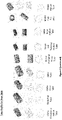
- Figure 1j and 1k shows preform shapes in various forms.
- the aerosol generating substrate is held together by binding agents and compressed by pressure to form these shapes.
- acetate tow to be used as an outer layer 106, as a base material forming part of the core layer 102, and/or as base material forming part of the intermediate layer 108.
- the outer layer 106 or wrapper comprises at least one layer of paper, metal, alloy, reconstituted tobacco sheet, cast leaf tobacco (CLT) sheet, acetate tow, heat stick wrapper plastic (including PLA, polypropylene such as biaxially-oriented polypropylene or BOPP), polymer, fiber (including natural fiber) and ceramic. If the wrapper is a metal, the metal may include aluminum or copper in a foil form.
- the aerosol generating product is a cylindrical rod having a length in a range from 5mm to 250mm.
- the single segment comprises a base ingredient having at least one of Propylene Glycol (PG) and Vegetable Glycerine/Glycerin (VG). Where both PG and VG are present, their total amount is less than 20 milligrams. In some embodiments, the ratio of PG: VG is 1:1.
- the aerosol generating product 100 may have an overall planer shape, i.e. having a dimension, such as thickness, much smaller than other dimensions, such as length and width.
- the planar shape is a prism or cylindrical shape.
- the aerosol generating product 100 may be casted, molded, or shaped, formed by rolling, pressing, stamping, formed by injection or extruding, reconstituting or combinations of one or more of the above, and any other process.
- the form of the aerosol generating substrate 102 may be one of the following: cut rag, compacted into shape, powder, dust, flakes, pellet, granules, tablet, pill, paper, block, porous block, sheet, net, fibers, fibers woven into sheet, slices, ribbons or combinations thereof.
- the aerosol generating product 100 may be designed for products made from loose tobacco/flavored non-tobacco and rolling paper (such as, but not limited to, roll your own (RYO) products) or other heat-not-burn devices.
- the aerosol generating product 100 may be configured in the form of a capsule.
- the heating device 200 comprises a mouthpiece/nose-piece 202 allowing a user to consume aerosol generated by the aerosol generating substrate; a substrate holder 204 for receiving an aerosol generating substrate a heating element 206 shaped and dimensioned to heat the aerosol generating substrate to produce aerosol; an aerosol delivery channel 208 positioned to receive aerosol generated from heating the aerosol generating substrate and to direct the aerosol towards the mouthpiece/nose-piece 202.
- the heating device 200 may be powered by electrical power, using a battery 214 that is contained within the heating device 200.
- the battery 214 may be a lithium-ion polymer (LiPo) battery.
- a charging port 216 may be provided in the device 200 to charge the LiPo battery.
- the charging port 216 may be a USB-type charging port or may be other known charging ports (including wireless charging ports).
- the battery 214 may be electrically connected to the heating element 206 such as to increase the temperature of the heating element 206 to a desired temperature or temperature profile.
- heat sinking areas or regions may be provided within the device 200.
- the heat sinking areas may comprise one or more metal coatings, plates and/or holders 240 positioned in a manner such as to reduce heat within the device 200.
- heat sinks in the form of fin-like structures may be positioned at a region proximate the mouthpiece/nose-piece 202.
- the heat sinks may be formed from manufacturing methods such as, but not limited to, extrusion, diecasting, machining process, 3D printing, investment casting and injection molding.
- the heat insulation wall 209 may be positioned adjacent the heat sink 207 so as to dissipate heat away from the substrate holder 204 and insulate heat from the surface of the device 200.
- the device 200 may comprise a jig 250 as an alternative to substrate holder 204 for receiving an aerosol generating product and/or at least one filter unit.
- the aerosol generating product may be the single-segment aerosol generating product 100.
- the jig 250 may comprise or may house a metal hollow or cup-shaped cylinder 207 to hold the aerosol generating product such that the cylinder 207 can be made of aluminum, copper, magnesium, stainless steel or other conductive material to extract heat away from the aerosol.
- the jig 250 may be adjustable for the length of the aerosol generating product for ease of insertion and removal of the aerosol generating product from the substrate holder 204.
- the jig may comprise a filter holder 210 for receiving at least one filter 212, the filter holder 210 positioned proximate the mouthpiece 202 in a manner such as to filter particulates from the generated aerosol before consumption by the user.
- the heating element 206 may have a sliding mechanism 213 such that the heating element 206 can be adjusted to move up and down to heat the aerosol generating product of different lengths.
- the sliding mechanism 213 may have biasing mechanisms as known to a skilled person to bias the element 206 at different positions to adapt to different aerosol generating product.
- the portion of the device 200 receiving the jig may be lined with insulation 244 (see Figure 2a(iii) ), in the form of material such as plastic, metal, fiber, glass, ceramic, carbon, aerogel, etc. to insulate the heat generated from the heating element 206.
- the insulation 244 may be in a form of a vacuum chamber surrounding the heating element and/or the jig 250.
- the base of the jig may comprise a slot or hole for insertion of heat element to contact the aerosol generating product 100.
- the aerosol generating product 100 is clamped between the jig 250 and the receiving portion 246 to prevent leakage of air.
- the receiving portion 246 may comprise two or more biasing mechanisms such that when the jig 250 is inserted, a force is exerted on the jig 250 to hold the jig 250 securely within the device 200. In operation, air may enter the device 200 from any air gaps 224 around the jig 250.
- the first part 200a which may be referred to as a device cap, houses the aerosol delivery channel 208, filter holder 210 (with filter 212 when present), substrate holder 204 (with substrate 205 when present).
- the second part 200b may be referred to as a device body, houses the battery 214, the charging port(s) 216, any pin reset/actuators for operating the device 218, and the heat sink(s) 240.
- the aerosol delivery channel 208 is a U-shaped channel arranged to connect an air pocket 220 (also referred to as an airflow pocket) located adjacent to the substrate holder 204 to the filter holder 210.
- Figure 2c is a cross-section view showing the device of Figure 2b in operation, with the aerosol generating substrate 205 contacting the heating element 206, and the filter 212 held in place by the filter holder 210.
- the heating element 206 is heated to a desired temperature. Consequently, the substrate 205, and the air surrounding the substrate within the air pocket 220 is heated. Air from the exterior of the device 200 is drawn into the device from around one or more air gaps/inlets 224 defined at the interface between the parts 200a, 200b, towards the substrate 205. The air flowing towards the substrate 205 may simultaneously be heated with the substrate 205, and may then flow pass the heat sinks 240, thereby reducing the temperature of the same. The air drawn to the substrate 205 carries aerosol generated via heating the substrate 205 towards the air pocket 220, and then to the U-shaped aerosol delivery channel 208.
- the aerosol delivery channel 208 may be coated with a layer of metal, such as aluminium, copper, magnesium, stainless steel or other conductive material (which effectively forms a heat sink) to extract heat away from the aerosol flowing pass the aerosol delivery channel 208 before entering the mouthpiece 202.
- Figure 2d shows another embodiment of the device 200.
- the part 200a may further comprise parts 200a1 and 200a2.
- Such an arrangement advantageously provides for a cover for easy replacement of a filter 212.
- Part 200a1 may be a referred to as a device cover, and part 200a2 a device cap.
- part 200a1 and part 200a2 house the aerosol delivery channel 208, filter holder 210 (with filter 212 when present), substrate holder 204 (with substrate 205 when present).
- the second part 200b may be referred to as a device body, houses the battery 214, the charging port(s) 216, any pin actuators (including actuators for reset, on/off, operational control) for operating the device 218, and the heat sink(s) 240.
- the aerosol delivery channel 208 is a straight channel and may be analogous to the air pocket 220 located adjacent to the substrate holder 204 to the filter holder 210.
- a singular piece of heat sink 240 comprising one or more metal, such as aluminium, copper, magnesium, stainless steel or other conductive material may be positioned proximate or adjoining the aerosol delivery channel 208 and the substrate holder 204 to aid dissipation of heat away from the aerosol delivery channel 208.
- the mouthpiece 202 may be coated with a layer of metal, such as aluminium, copper, magnesium, stainless steel or other conductive material (which effectively forms a heat sink) to extract heat away from the aerosol flowing pass the mouthpiece 202.
- a layer of metal such as aluminium, copper, magnesium, stainless steel or other conductive material (which effectively forms a heat sink) to extract heat away from the aerosol flowing pass the mouthpiece 202.
- Figure 2e is a cross-sectional view showing the device of Figure 2d in operation, with the aerosol generating substrate 205 contacting the heating element 206, and the filter 212 held in place by the filter holder 210.
- the heating element 206 is heated to a desired temperature. Consequently, the substrate 205, and the air surrounding the substrate within the aerosol delivery channel 208 (air pocket 220) is heated. Air from the exterior of the device 200 is drawn into the device from around one or more air gaps/inlets 224 defined at the interface between the parts 200a, 200b towards the substrate 205. The air flowing towards the substrate 205, that may simultaneously be heated, may flow pass the heat sink(s) 240, thereby reducing the temperature of the same.
- the air drawn to the substrate 205 carries aerosol generated via heating the substrate 205 towards the air pocket 220, and then to the aerosol delivery channel 208 adjoining the substrate holder 204.
- the heat sink 240 positioned adjoining the aerosol delivery channel 208, further aids to dissipate heat away from the aerosol delivery channel 208.
- Figure 2f is another embodiment of the device 200.
- the aerosol delivery channel shown in Figure 2f is Z-shape.
- the embodiment of Figure 2f also shows the part 200a housing the substrate holder 204 only, with other components housed by the part 200b.
- the substrate holder 204 may be shaped and dimensioned as a hollow tube for receiving a corresponding substrate 205 within the holder.
- mechanical gaskets such as O-rings 260 maybe positioned at various joints.
- the cup-like or cylinder structure 207 may line the substrate holder 204 to receive the substrate 205.
- Figure 2g is a cross-sectional view showing the device of Figure 2f in operation, with the aerosol generating substrate 205 contacting the heating element 206, and the filter 212 held in place by the filter holder 210.
- the heating element 206 is heated to a desired temperature. Consequently, the substrate 205, and the air surrounding the substrate within the aerosol delivery channel 208 (air pocket 220) is heated. Air from the exterior of the device 200 is drawn into the device from around one or more air gaps/inlets 224 defined at the interface between the parts 200a, 200b towards the substrate 205. The air drawn to the substrate 205 carries aerosol generated via heating the substrate 205 towards the air pocket 220, which forms part of the aerosol delivery channel 208 adjoining the substrate holder 204. A layer of metal is coated over part of the aerosol delivery channel 208 to facilitate heat transfer. One or more heat sink(s) 240, positioned adjoining the aerosol delivery channel 208, further aids to dissipate heat away from the aerosol delivery channel 208.
- the aerosol delivery channel 208 and the mouthpiece 202 of each embodiment may both be coated with conductive material to form yet further embodiments.
- O-rings 260 or other suitable gaskets may be positioned in the devices 200 as shown in Figure 2b and 2d .
- the coating over the aerosol delivery channel and/or mouthpiece may be regarded as a first heat conductor.
- the metallic plates proximate the aerosol delivery channel may be regarded as a second heat conductor operable to dissipate heat away from the first heat conductor.
- Figure 2h shows an embodiment having an external profile similar to the device shown in Figure 2d .
- the device cover 200a1 may be rotatable with respect to device cap 200a2 to removably detach the device cover 200a1 from the device cap 200a2.
- the device cap 200a2 comprises a slot for receiving the jig 250, except that in the embodiment shown in Figure 2h the mouthpiece 202 is not part of the jig 250.
- a compartment of the jig 250 for receiving the aerosol generating substrate may be lined/coated with suitable heat conducting material.
- Figure 2i illustrates an embodiment of the jig 250, wherein the part of the jig 250 receiving the aerosol generating substrate allows for excess material to be pushed out from the substrate when in use. Suitable openings/gaps are formed on the jig 250 so as to allow for the excess material to be pushed out of the jig 250.
- Figure 2j illustrates another embodiment that is suitable for use with the various embodiments in Figure 2a to 2i , wherein heat sinks in the form of fin-like structures may be positioned at a region proximate the mouthpiece/nose-piece 202.
- the heat sinks may be formed from manufacturing methods such as, but not limited to, extrusion, diecasting, machining process, 3D printing, investment casting and injection molding.
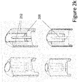
- Figure 2k illustrates embodiments wherein the region/walls surrounding the heating element 206 may be coated/layered with metal, such as aluminium, copper, stainless steel, or alloy 252 in the form of fibre, strips, sheet, chips, powder or granules.
- the outer surface of the device 200 i.e. the surface coming into direct contact with the environment, may be formed from or of a metal or alloy, such as aluminum alloy, or plastic.
- one or more temperature sensors may be positioned in the device 200 to provide feedback on the aerosol temperature.
- the feedback may then be sent to a controller (not shown) for the provision of temperature control in accordance with one or more heating profiles (see Figures 4a to 4e ).
- the controller may be in the form of an integrated circuit chip (IC), such as, but not limited to, an application specific integrated circuit (ASIC) chip.
- IC integrated circuit chip
- ASIC application specific integrated circuit
- the devices 200 work on the principle to separate an aerosol generating substrate (e.g. tobacco), from the filter. This is especially suited for a single segment embodiment of the aerosol generating product 100.
- the additional filter 212 may not be required in operation and the slot 210 may be left empty.
- the aerosol delivery channel 208 and/or mouthpiece may be coated with heat dissipation material or heat sink.
- a suitable material may be a metal or alloy, such as an aluminium alloy, magnesium, stainless steel or other conductive material to extract heat away from the mouthpiece 202.
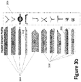
- Figures 3a to 3c show various embodiments of heating elements for use with a heating device, such as, but not limited to heating device 200 to heat at least one aerosol generating substrate without combustion of the at least one aerosol generating substrate, such as, but not limited to aerosol generating substrate 102, wherein the heater element 302 is shaped and dimensioned to be in thermal contact with the at least one aerosol generating product.
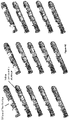
- Figure 3d shows various embodiments where at least one heating pin 314 is positioned adjacent to the heater element 302 to provide homogenous temperature control within the aerosol generating product, the at least one heating pin 314 is formed from or of a metal, an alloy, ceramic, nickel plating, and silver, or other composite material with or without coating.
- the heating pin 314 may be shaped and dimensioned as having a substantially thinner width compared to the heater element 302.
- the heating element can comprise an elongate body portion, a first end 304 adapted to receive electrical power, and a second end adapted to provide optimum contact with the aerosol generating substrate.
- the second end 306 of the heating element comprises a rounded tip or a tapered tip.
- the tapered tip 306 may be a frusto-conical tip or may comprise one or more chamfered surfaces, or a circular cross-section with at least two indented portions.
- the inside of the tip 306 may be hollow or partially hollow.
- the internal of the elongate body portion may be hollow or partially hollow.
- the elongate body portion of the heating element has a at least one of a L-shaped cross-section, a V-shaped cross-section, a phi-shaped cross-section, a C-shaped cross-section, a J-shaped cross-section, an X-shaped cross-section, a Y-shaped cross-section, a T-shaped cross-section, a triangular-shaped cross-section or a rectangular-shaped cross-section.
- the heating element has a coin or planar shape 308.
- the heating element 310 is cylindrical in shape such that the inner surface of the cylinder 312 is in thermal contact with the aerosol generating product 102.
- the heating may be effected by an inductor or inductor element
- the body portion is formed from or of alumina. In other embodiments, the body portion may be form of/from other materials such as glass/glass fiber.
- heating element shown in Figures 3a to 3c are in the form of an elongate tube and can be hollow to receive electrical circuitry or substrate, it is appreciable that other shapes and sizes may be contemplated to receive aerosol generating substrate of different shapes and sizes.
- a controller for use with a heating device, such as a heating device 200 as described in Figures 2a to 2k .
- the controller may include sensors for sensing a temperature and/or pressure of the heating element of the heating device.
- the heating device may include one or more of the sensors.
- the pressure sensor may be configured for sensing a pressure corresponding to a suction force exerted on a mouthpiece of the heating device.
- the suction force may in turn correspond with a user consuming the aerosol via his/her mouth (i.e. 'taking a puff).
- an electrical circuit may be arranged to directly send electrical current to the heating element or to induce electrical current flowing through the heating element.
- the controller may be arranged to raise the temperature from room temperature to achieve a first resting temperature and a first operating temperature, wherein the first operating temperature is associated with the suction force detected by the pressure sensor.
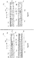
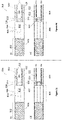
- Figures 4a to 4e show five heating profiles corresponding various resting temperatures and operating temperatures.
- Figure 4a shows the controller programmed to provide a first heating profile.
- the first heating profile comprises the first resting temperature at between 200 degrees Celsius (°C) and 400°C, and the first operating temperature above 200°C and up to 400 °C.
- the heating element is heated from room/ambient temperature to the first resting temperature.
- the controller operates to heat the heating element to an operating temperature of up to 400 °C.
- the suction force is no longer applied, the temperature of the heating element falls back to the first resting temperature. This process repeats itself until reset or the aerosol generating substrate is consumed.
- the first resting temperature may be in a range from 300°C to 350°C.
- Figure 4b shows the controller programmed to provide a second heating profile.
- the second heating profile comprises the first resting temperature at a temperature range of 250 °C to 400 °C, and the first operating temperature lower than the first resting temperature and at a temperature in a range of 200 °C to 350 °C, and a second resting temperature above the first operating temperature, the second resting temperature below the first resting temperature.
- the heating element is heated from room/ambient temperature to the first resting temperature.
- the controller operates to cool the heating element to an operating temperature of around 200 °C.
- the suction force is no longer applied, the temperature of the heating element rises to the first resting temperature.
- the temperature of the heating element is maintained at a second resting temperature regardless of whether subsequent suction force is detected by the pressure sensor.
- the predetermined number of 'puffs' may be three puffs, and the second resting temperature may be a temperature below the first resting temperature but higher than the first operating temperature.
- Figure 4c shows the controller programmed to provide a third heating profile.
- the third heating profile comprises the first resting temperature at a range from 200 degrees Celsius (°C) to 400°C, a second resting temperature below the first resting temperature at above 200 °C, the first operating temperature less than the first resting temperature and at least 200 °C, and a second operating temperature above the second resting temperature up to 400 °C.
- the heating element is heated from room/ambient temperature to the first resting temperature.
- the controller operates to cool the heating element to an operating temperature of around 200 °C.
- the suction force is no longer applied, the temperature of the heating element rises to the first resting temperature.
- the temperature of the heating element drops to the second resting temperature.
- the controller operates to heat the heating element to an operating temperature of up to 400 °C, and the second resting temperature is at a temperature below the first resting temperature but higher than the first operating temperature.
- the third heating profile may be regarded as a combination of the second heating profile and the first heating profile.
- Figure 4d shows the controller programmed to provide a fourth heating profile.
- the fourth heating profile may comprise the first resting temperature at a range from 200 degrees Celsius (°C) to 400°C, the first operating temperature above the first resting temperature and up to 400 °C, and a second operating temperature above 200°C and below the first resting temperature.
- the heating element is heated from room/ambient temperature to the first resting temperature.
- the controller operates to increase the heating element to an operating temperature of around 400 °C.
- the suction force is no longer applied, the temperature of the heating element drops to the first resting temperature.
- a predetermined number of 'puffs' e.g.
- the fourth heating profile may be regarded as a combination of the first heating profile and the second heating profile.
- Figure 4e shows the controller programmed to provide a fifth heating profile.
- the fifth heating profile may comprise the first resting temperature at a range from 200 degrees Celsius (°C) to 400°C, and a first operating temperature above the first resting temperature and up to 400 °C.
- the heating element is heated from room/ambient temperature to the first resting temperature.
- the controller operates to increase the heating element to an operating temperature of around 400 °C.
- the suction force is no longer applied, the temperature of the heating element is maintained at the operating temperature.
- the controller may control the heating profiles of the heating element by logical instructions or software programs pre-loaded into the controller.
- the controller may control the heating profiles of the heating element dynamically based on input and feedback from the temperature sensors and pressure sensors placed in the heating device (e.g. device 200) to track the actual temperature and pressure of the aerosol.
- FIG. 5a shows a filter unit 500 suited for use with the heating device described in the previous embodiments.
- the filter unit 500 comprises a core layer 502, an outer layer 504 and an intermediate layer 506 sandwiched between the core layer 502 and the outer layer 504.
- the core layer 502 and outer layer 504 are formed from or of materials comprising acetate tow, fiber (including synthetic and natural fiber), cotton, fabric, mesh and/or paper (including coated paper).
- the intermediate layer 506 may comprise a single layer with paper or a multi-layered structure including materials such as metal (including aluminum copper, in foil/sheet form or otherwise), alloy, reconstituted tobacco sheet, paper (including coated paper), plastic (including PLA and BOPP), polymer, fiber (including natural fiber) and ceramic.
- the filter unit 500 may be shaped and dimensioned as a rod. It is appreciable that the various layers may be arranged coaxially with respect to each other.
- Figure 5b shows a variant of Figure 5a having the core layer 502 partially hollow, defining a hollow portion 510.
- the intermediate layer 512 may or may not extend to the hollow portion 510.
- Figure 5c illustrate another variant of Figure 5a wherein the core layer 502 is partially hollow, defining a hollow portion 510. Unlike the embodiment shown in Figure 5b , the embodiment shown in Figure 5c does not have the intermediate layer 512.
- Figure 6 (6a to 6f) relate to a substrate holder 600, also referred to as a jig, for use one or more of the heating devices 200, in particular the embodiment shown in Figure 2a .
- the substrate holder 600 may be configured to hold different one or more single-segment aerosol generating product including as shown in Figures 1a to 1k , one or more two-segment aerosol generating product including as shown in Figures 7a to 71 , one or more three-segment aerosol generating product including as shown in Figures 8a to 8n , and/or one or more filter segments including as shown in Figures 5a, 5b and 5c .
- the substrate holder 600 comprises a mouthpiece 602, an elongate structure 604 comprising a plurality of compartments 606, and an end portion 608 arranged distally with respect to the mouthpiece 602.
- Figure 6a shows a substrate holder 600 having a first compartment 610 positioned proximate the distal end portion 608 and one or more second compartments 612 adjacent the mouthpiece 602.
- the first compartment 610 is shaped and dimensioned to receive a single-segment aerosol generating product including as shown in any one of Figures 1a to 1k , two-segment aerosol generating product including as shown in Figures 7a to 7l , or three-segment aerosol generating product including as shown in Figures 8a to 8n .
- On the end portion 608 is formed a through-hole such that in operation, a heating element of the heating device 200 can contact the single-segment aerosol generating product 100 to generate aerosol therefrom.
- the first compartment 610 may be coated or installed with one or more heat conductors 614.
- the one or more heat conductors 614 may be shaped and dimensioned to be inserted into the first compartment 610 without hindering the first compartment 610 ability to receive the single-segment aerosol generating product.
- the one or more second compartments 612 are shaped and dimensioned to receive a filter unit including as shown in Figures 5a, 5b and 5c and/or a heat dissipation tube 618.
- the heat dissipation tube 618 may be an aluminum tube. Where there are a plurality of second compartments 612 and the heat dissipation tube 618 is placed in one compartment of the plurality of second compartments 612, the filter unit will have to be placed in another compartment of the plurality of second compartments 612.
- the third compartment(s) 616 function as a connecting portion between the first compartment 610 and the second compartment 612, and may typically be formed of or from less material compared to the first compartment 610 and the second compartment(s) 612, as the third compartment 616 does not receive any aerosol generating product(s) or filter unit(s).
- the less material associated with the third compartment 616 advantageously reduce heat transfer to the second compartment(s) 612.
- first compartment 610 there comprise one first compartment 610, two second compartments 612, and one third compartment 616.
- Figure 6b shows another embodiment of the jig with one first component 610 and three second compartments 612. There is no third compartment 616 in the embodiment of Figure 6b . At least one of the three second compartments 612 function as the connector between the first compartment 610 and the other second compartment 612.
- one or more second compartments 612 can be enclosed or covered.
- the covered or enclosed second compartments 612 can contain the aluminum tube 618.
- Figure 6c to 6f show various embodiments of the jig 600 wherein there are different configurations/positioning of an aluminum tube 618 or other heat conductive metal or metal alloy, the aerosol generating substrate, and the filter unit.
- Figure 7 (7a to 71) show various embodiments of a two-segment aerosol generating product 700.
- the product 700 can incorporate any one of the single-segment products depicted in Figure 1a to 1k , and/or any one of the filter unit depicted in Figure 5a, Figure 5b and Figure 5c .
- Figure 7a(i) and 7a(ii) show an embodiment of a two-segment aerosol generating product 700 with an aerosol generating segment (first segment) 702 and an integrated support filter segment (second segment) 704.
- the second segment 704 comprises a core acetate tow portion 706 positioned at an opposite end from the first segment 704 and a support portion 708 positioned between the first segment 702 and the core acetate tow portion 706.
- the support portion 708 comprises an acetate tow layer 710 having a central hollow portion defining a channel 712.
- An air space 714 may be positioned between the acetate tow layer 710 and the core acetate tow portion 706.
- An intermediate layer 716 comprises a first inner layer 718 layered on the core acetate tow portion 706, and a second inner layer 720 layered on the first inner layer 718 and the acetate tow layer 710.
- the second inner layer 720 extends longitudinally across the entire second segment 704.
- Each of the first inner layer 718 and/or the second inner layer 720 comprises at least one of paper (including coated paper), metal, alloy, reconstituted tobacco sheet, plastic (including PLA and BOPP), polymer and ceramic, etc. is overlay on the core acetate tow layer 706.
- intermediate layer 716 may be at least one outer layer 722 comprising acetate tow, fiber (including synthetic and natural fiber), cotton, fabric, mesh and/or paper (including coated paper).
- the outer layer 722 spans the entire second segment 704.
- the entire two-segment aerosol generating product 700 may be wrapped by an outer cover 724.
- the outer cover 724 may be a layer of paper (including coated paper).
- At least one airflow inlet 726 may be formed on the outer cover in a manner such as to allow air flow through the outer layer 722 comprising acetate tow, fiber (including synthetic and natural fiber), cotton, fabric, mesh and/or paper (including coated paper).
- the embodiment shown in Figure 7a(ii) shows the airflow inlet 726 extending to the air space 714 in a manner such as to allow air flow through the core acetate tow portion 706.
- the embodiment shown in Figure 7b(i) is similar to the embodiment of Figure 7a(i) , except that the air space 714 is filled with or replaced by a tobacco or charcoal part 728, and the channel 712 may comprises two or more different parts.
- the embodiment shown in Figure 7b(ii) is similar to the embodiment of Figure 7a(ii) , except that the air space 714 is filled with or replaced by a tobacco or charcoal part 728, and the channel 712 may comprises two or more different parts.
- Figures 7c(i) and 7c(ii) illustrate embodiments wherein the air space 714 is replaced with or lined with a tube 730.
- the tube 730 may be formed of or from one or more of the following metal or metallic alloy, such as but not limited to copper, aluminium, silver, nickel, tin, and/or alloys of the same.
- the tube 730 may be a hollow or partially hollow tube with different profiles such as cross, star, circle, mesh, forming, multiple circles etc.
- the tube may be wrapped with paper or reconstituted tobacco sheets.
- At least one airflow inlet 726 may be formed on the outer cover in a manner such as to allow air flow through the outer layer 722 comprising acetate tow, fiber (including synthetic and natural fiber), cotton, fabric, mesh and/or paper (including coated paper).
- the embodiment shown in Figure 7c(ii) shows the airflow inlet 726 extending to the tube 730 in a manner such as to allow air flow through the core acetate tow portion 706.
- FIG. 7d(i) is similar to the embodiment of Figure 7c(i) , except that the channel 712 is partially filled with a tobacco or charcoal part 732.
- the embodiment shown in Figure 7d(ii) is similar to the embodiment of Figure 7c(ii) , except that the channel 712 is partially filled with a tobacco or charcoal part 732.
- Figures 7e(i) and 7e(ii) illustrate embodiments wherein the tube 730 extends or spans a length of the entire second segment, and forms an inner layer sandwiched between the acetate tow layer 710 and outer layer 722 comprising acetate tow, fiber (including synthetic and natural fiber), cotton, fabric, mesh and/or paper (including coated paper).
- the tube 730 may be formed of or from one or more of the following metal or metallic alloy, such as but not limited to copper, aluminium, silver, nickel, tin, and/or alloys of the same.
- the tube 730 may be a hollow or partially hollow tube with different profiles such as cross, star, circle, mesh, forming, multiple circles etc.
- At least one airflow inlet 726 may be formed on the outer cover in a manner such as to allow air flow through the outer layer 722 comprising acetate tow, fiber (including synthetic and natural fiber), cotton, fabric, mesh and/or paper (including coated paper).
- the embodiment shown in Figure 7e(ii) shows the airflow inlet 726 extending to the tube 730 in a manner such as to allow air flow through the core acetate tow portion 706.
- FIG. 7f(i) is similar to the embodiment of Figure 7e(i) , except that the channel 712 is partially filled with a tobacco or charcoal part 732.
- the embodiment shown in Figure 7f(ii) is similar to the embodiment of Figure 7e(ii) , except that the channel 712 is partially filled with a tobacco or charcoal part 732.
- Figures 7g(i) and 7g(ii) illustrate embodiments wherein instead of the metal or metallic alloy tube 730, an inner wrapping material 734 is formed from or of one or more metallic layers (e.g. copper, aluminium, nickel, tin or silver) and/or at least one of a reconstituted tobacco sheet, paper (including coated paper), plastic (including PLA and BOPP), polymer ceramic, etc.
- metallic layers e.g. copper, aluminium, nickel, tin or silver
- At least one airflow inlet 726 may be formed on the outer cover in a manner such as to allow air flow through the outer layer 722 comprising acetate tow, fiber (including synthetic and natural fiber), cotton, fabric, mesh and/or paper (including coated paper).
- the embodiment shown in Figure 7g(ii) shows the airflow inlet 726 extending to the inner wrapping material 734 in a manner such as to allow air flow through the core acetate tow portion 706.
- FIG. 7h(i) is similar to the embodiment of Figure 7g(i) , except that the channel 712 is partially filled with a tobacco or charcoal part 732.
- the embodiment shown in Figure 7h(ii) is similar to the embodiment of Figure 7g(ii) , except that the channel 712 is partially filled with a tobacco or charcoal part 732.
- Figures 7i(i), 7i(ii) show embodiments similar to Figures 7g(i) and 7g(ii) respectively, wherein in addition to the inner wrapping material 734, there comprises an additional acetate tow layer 736 with or without metal.
- the material can include at least one of fiber, strips, sheet, chips, powder or granules.
- Figures 7j(i) and 7j(ii) show embodiments similar to Figures 7h(i) and 7h(ii) respectively, with the additional acetate tow layer 736.
- Figures 7k(i) and 7k(ii) shows embodiments similar to Figures 7g(i) and 7g(ii) respectively, with an extended air space 714 and a shortened acetate tow portion 706.
- the metal tube 730 includes at least one of the following metal copper, aluminum, nickel, tin or silver in various surface configuration including straight, twisting, embossing, crimping forming to shape or alloy or paper or multi-layer including with metal such as aluminum or copper foil, alloy, reconstituted tobacco sheet, paper (including coated paper), plastic (including PLA and BOPP), polymer, ceramic, etc.
- Figures 7l(i) and 7l(ii) are similar to Figures 7k(i) and 7k(ii) , except that the metal tube 730 is extended to line part of the channel 712.
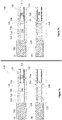
- Figure 8 (8a to 8h) show various embodiments of a three-segment aerosol generating product 800.
- the product 800 can incorporate any one of the single-segment aerosol generating products including those depicted in Figures 1a to 1k , and/or any one of the filter unit including those depicted in Figures 5a to 5c .
- Figure 8a(i) and 8a(ii) show an embodiment of a three-segment aerosol generating product 800 with an aerosol generating segment (first segment) 802, a filter segment (second segment) 804, and a support segment 808 (third segment).
- the second segment 804 comprises a core acetate tow portion 806 positioned at an opposite end from the first segment 802.
- the support segment 808 may be a support portion positioned between the first segment 802 and the core acetate tow portion 806.
- the support portion 808 comprises an acetate tow layer 810 having a central hollow portion defining a channel 812.
- An air space 814 may be positioned between the acetate tow layer 810 and the core acetate tow portion 806.
- An intermediate layer 816 comprises a first inner layer 818 layered on the core acetate tow portion 806, and a second inner layer 820 layered on the first inner layer 818 and the empty space 814.
- the second inner layer 820 extends longitudinally across the entire second segment 804.
- Each of the first inner layer 818 and/or the second inner layer 820 comprises at least one of paper (including coated paper), metal, alloy, reconstituted tobacco sheet, plastic (including PLA and BOPP), polymer, ceramic, etc, is overlay on the core acetate tow layer 806.
- intermediate layer 816 may be at least one outer layer of 822 comprising acetate tow, fiber (including synthetic and natural fiber), cotton, fabric, mesh and/or paper (including coated paper).
- the outer layer 822 spans the entire second segment 804.
- the entire three-segment aerosol generating product 800 may be wrapped by an outer cover 824.
- the outer cover 824 may be a layer of paper (including coated paper).
- At least one airflow inlet 826 may be formed on the outer cover in a manner such as to allow air flow through the outer layer 822 comprising acetate tow, fiber (including synthetic and natural fiber), cotton, fabric, mesh and/or paper (including coated paper).
- the embodiment shown in Figure 8a(ii) shows the airflow inlet 826 extending to the air space 814 in a manner such as to allow air flow through the core acetate tow portion 806.
- FIG. 8b(i) is similar to the embodiment of Figure 8a(i) , except that the air space 814 is filled with or replaced by a tobacco or charcoal part 828.
- the embodiment shown in Figure 8b(ii) is similar to the embodiment of Figure 8a(ii) , except that the air space 814 is filled with or replaced by the tobacco or charcoal part 828.
- Figures 8c(i) and 8c(ii) illustrate embodiments wherein the air space 814 is replaced with or lined with a tube 830.
- the tube 830 may be formed of or from one or more of the following metal or metallic alloy, such as but not limited to copper, aluminium, silver, nickel, tin, and/or alloys of the same.
- the tube 830 may be a hollow or partially hollow tube with different profiles such as cross, star, circle, mesh, forming, multiple circles etc.
- the tube may be wrapped with paper (including coated paper) or reconstituted tobacco sheets.
- At least one airflow inlet 826 may be formed on the outer cover in a manner such as to allow air flow through the outer layer 822 comprising acetate tow, fiber (including synthetic and natural fiber), cotton, fabric, mesh and/or paper (including coated paper).
- the embodiment shown in Figure 8c(ii) shows the airflow inlet 826 extending to the tube 830 in a manner such as to allow air flow through the core acetate tow portion 806.
- FIG. 8d(i) is similar to the embodiment of Figure 8c(i) , except that the space 814 is partially or wholly filled with a tobacco or charcoal part 832.
- the embodiment shown in Figure 8d(ii) is similar to the embodiment of Figure 8c(ii) , except that the space 814 is partially or wholly filled with a tobacco or charcoal part 832.
- Figures 8e(i) and 8e(ii) illustrate embodiments wherein the tube 830 extends or spans a length of the entire second segment, and forms an inner wrapping layer sandwiched between the acetate tow layer 810 and outer layer 822 comprising acetate tow, fiber (including synthetic and natural fiber), cotton, fabric, mesh and/or paper (including coated paper).
- the tube 830 may be formed of or from one or more of the following metal or metallic alloy, such as but not limited to copper, aluminium, silver, nickel, tin, and/or alloys of the same.
- the tube 830 may be a hollow or partially hollow tube with different profiles such as cross, star, circle, mesh, forming, multiple circles etc.
- At least one airflow inlet 826 may be formed on the outer cover in a manner such as to allow air flow through the outer layer 822 comprising acetate tow, fiber (including synthetic and natural fiber), cotton, fabric, mesh and/or paper (including coated paper).
- the embodiment shown in Figure 8e(ii) shows the airflow inlet 826 extending to the tube 830 in a manner such as to allow air flow through the core acetate tow portion 806 via the air space 814.
- FIG. 8f(i) is similar to the embodiment of Figure 8e(i) , except that the air space 814 is partially or wholly filled with a tobacco or charcoal part 832.
- the embodiment shown in Figure 8f(ii) is similar to the embodiment of Figure 8e(ii) , except that the air space 814 is partially or wholly filled with a tobacco or charcoal part 832.
- Figures 8g(i) and 8g(ii) illustrate embodiments wherein an inner wrapping material 834 formed from or of one or more metallic layers (e.g. copper, aluminium, nickel, tin or silver) and/or at least one of a reconstituted tobacco sheet, paper (including coated paper), plastic (including PLA and BOPP), polymer, ceramic, etc., may be layered on an inner circumference of the acetate tow layer 810 which defines the channel 812.
- metallic layers e.g. copper, aluminium, nickel, tin or silver
- At least one airflow inlet 826 may be formed on the outer cover in a manner such as to allow air flow through the outer layer 822 comprising acetate tow, fiber (including synthetic and natural fiber), cotton, fabric, mesh and/or paper (including coated paper).
- the embodiment shown in Figure 8g(ii) shows the airflow inlet 826 extending to the inner wrapping material in a manner such as to allow air flow through the core acetate tow portion 806.
- FIG. 8h(i) is similar to the embodiment of Figure 8g(i) , except that the channel 812 is partially filled with a tobacco or charcoal part 832.
- the embodiment shown in Figure 8h(ii) is similar to the embodiment of Figure 8g(ii) , except that the channel 812 is partially filled with a tobacco or charcoal part 832.
- Figures 8i(i) and 8i(ii) show similar embodiments as Figures 8g(i) and 8g(ii) respectively, the acetate tow layer 810 includes acetate tow with or without metal, and wherein the material includes at least one of fiber, strips, sheet, chips, powder or granules.
- Figures 8j(i) and 8j(ii) show similar embodiments as Figures 8h(i) and 8h(ii) respectively, the acetate tow layer 810 includes acetate tow with or without metal, and wherein the material includes at least one of fiber, strips, sheet, chips, powder or granules.
- Figures 8k(i) and 8k(ii) shows embodiments similar to Figures 8c(i) and 8c(ii) respectively, with an extended air space 814 and a shortened acetate tow portion 806.
- the metal tube 830 includes at least one of the following metal copper, aluminum, nickel, tin or silver in various surface configuration including straight, twisting, embossing, crimping forming to shape or alloy with paper (including coated paper) or multi-layer including with metal such as aluminum or copper foil, reconstituted tobacco sheet, paper (including coated paper), plastic (including PLA and bOPP), polymer, ceramic, etc.
- Figures 8l(i) and 8l(ii) are similar to Figures 8k(i) and 8k(ii) , except that the metal tube 830 is extended to line part of the channel 812.
- Figures 8m(i) and 8m(ii) show the metal tube 830 extending transversely across one end of the air space 814 to form a cup shape.
- Figures 8n(i) and 8n(ii) show the metal tube 830 extending transversely across another end of the air space 814 to form a cup shape.
- the tube material associated with the aerosol generating product can be metal (including copper, aluminum, silver, nickel or tin) or alloy, in hollow tube with different shapes i.e. cross, star, hollow circle, mesh/netting, and formed via multiple circle, twisting, crimping, forming, embossing profile wrapped with paper or multi-layer, including with metal (including copper, aluminum foil), alloy, reconstituted tobacco sheet, paper (coated paper), plastic (including PLA and BOPP), polymer, ceramic, etc.
- the cross-section of a tube material may be shaped as a circle embossing, circle flat, circle cross, spiral, metal foil spiral straw, metal foil twisting hollow, metal rope hollow, metal cup, shape hollow, etc (see Figure 9 ). It is appreciable that the tube material may be formed as an intermediate layer to minimize absorption of flavours by filter materials such as acetate tow, and yet providing heat dissipation.
- the metal/alloy tube constituting the inner wrapping in the filter can be shaped and dimensioned as a metal/alloy cup.
- the metal/alloy tube and cup constituting the inner wrapping in the filter can have additional profiles of twisted, embossed, crimped, roped, piped, spiraled and other forms to shape.
- the materials of the metal/alloy tube and cup can be metal, aluminum foil, aluminum alloy, metal alloy, etc.
- the metal/alloy tube and cup can be made by embossing, crimping, compressed extrusion, forming, die casting, extrusion, flow wrapping and any other methods of manufacture of the metal/alloy tube and cup.
- the heating device can include a metal cup structure (such as the cylinder or cup structure 207) to hold the aerosol generating product. It is also contemplated that one or more ventilation device(s), e.g. a fan can be added into the device to provide cooling.
- a metal cup structure such as the cylinder or cup structure 207
- one or more ventilation device(s) e.g. a fan can be added into the device to provide cooling.
- the at least a layer of the single segment and/or multi-segment aerosol generating product may comprise two surface, with an outer surface coated with paper and an inner surface coated with metal (including copper, aluminium, silver, nickel, or tin), or metallic alloy foil laminate, reconstituted tobacco sheet, paper (including coated paper), plastic (including PLA and BOPP), polymer, ceramic, etc.), before being formed onto a desired shape, such as tubular shape.
- metal including copper, aluminium, silver, nickel, or tin
- metallic alloy foil laminate metallic alloy foil laminate
Landscapes
- Chemical & Material Sciences (AREA)
- Engineering & Computer Science (AREA)
- Materials Engineering (AREA)
- Resistance Heating (AREA)
- Instantaneous Water Boilers, Portable Hot-Water Supply Apparatuses, And Control Of Portable Hot-Water Supply Apparatuses (AREA)
- Cigarettes, Filters, And Manufacturing Of Filters (AREA)
- Electric Connection Of Electric Components To Printed Circuits (AREA)
Priority Applications (10)
| Application Number | Priority Date | Filing Date | Title |
|---|---|---|---|
| EP21165276.3A EP4062780A1 (fr) | 2021-03-26 | 2021-03-26 | Gabarit pour usage avec élément de chauffage pour dispositif de génération d'aérosol |
| BR112023019632A BR112023019632A2 (pt) | 2021-03-26 | 2022-03-25 | Dispositivo de aquecimento, elemento de aquecimento e produto gerador de aerossol |
| PCT/SG2022/050164 WO2022203609A1 (fr) | 2021-03-26 | 2022-03-25 | Dispositif de chauffage, élément chauffant et produit de génération d'aérosol |
| KR1020237027788A KR20230161944A (ko) | 2021-03-26 | 2022-03-25 | 가열 장치, 가열 요소 및 에어로졸 발생 제품 |
| CN202280011692.2A CN116744809A (zh) | 2021-03-26 | 2022-03-25 | 加热装置、加热元件和气溶胶产生产品 |
| TW111111411A TWI835097B (zh) | 2021-03-26 | 2022-03-25 | 加熱裝置 |
| JP2023545223A JP2024510543A (ja) | 2021-03-26 | 2022-03-25 | 加熱デバイス、加熱エレメント、およびエアロゾル発生製品 |
| CA3204895A CA3204895A1 (fr) | 2021-03-26 | 2022-03-25 | Dispositif de chauffage, element chauffant et produit de generation d'aerosol |
| EP22776250.7A EP4312611A1 (fr) | 2021-03-26 | 2022-03-25 | Dispositif de chauffage, élément chauffant et produit de génération d'aérosol |
| CONC2023/0013092A CO2023013092A2 (es) | 2021-03-26 | 2023-09-29 | Dispositivo de calentamiento, elemento de calentamiento y producto generador de aerosol |
Applications Claiming Priority (1)
| Application Number | Priority Date | Filing Date | Title |
|---|---|---|---|
| EP21165276.3A EP4062780A1 (fr) | 2021-03-26 | 2021-03-26 | Gabarit pour usage avec élément de chauffage pour dispositif de génération d'aérosol |
Publications (1)
| Publication Number | Publication Date |
|---|---|
| EP4062780A1 true EP4062780A1 (fr) | 2022-09-28 |
Family
ID=75252441
Family Applications (2)
| Application Number | Title | Priority Date | Filing Date |
|---|---|---|---|
| EP21165276.3A Pending EP4062780A1 (fr) | 2021-03-26 | 2021-03-26 | Gabarit pour usage avec élément de chauffage pour dispositif de génération d'aérosol |
| EP22776250.7A Pending EP4312611A1 (fr) | 2021-03-26 | 2022-03-25 | Dispositif de chauffage, élément chauffant et produit de génération d'aérosol |
Family Applications After (1)
| Application Number | Title | Priority Date | Filing Date |
|---|---|---|---|
| EP22776250.7A Pending EP4312611A1 (fr) | 2021-03-26 | 2022-03-25 | Dispositif de chauffage, élément chauffant et produit de génération d'aérosol |
Country Status (8)
| Country | Link |
|---|---|
| EP (2) | EP4062780A1 (fr) |
| JP (1) | JP2024510543A (fr) |
| KR (1) | KR20230161944A (fr) |
| CN (1) | CN116744809A (fr) |
| BR (1) | BR112023019632A2 (fr) |
| CA (1) | CA3204895A1 (fr) |
| CO (1) | CO2023013092A2 (fr) |
| WO (1) | WO2022203609A1 (fr) |
Citations (3)
| Publication number | Priority date | Publication date | Assignee | Title |
|---|---|---|---|---|
| WO2017202965A1 (fr) * | 2016-05-25 | 2017-11-30 | Philip Morris Products S.A. | Procédé pour fournir un dispositif générateur d'aérosol, dispositif générateur d'aérosol et article plat générateur d'aérosol destiné à être utilisé dans un tel dispositif |
| KR20200120553A (ko) * | 2019-04-11 | 2020-10-21 | 인텔렉추얼디스커버리 주식회사 | 가열식 담배의 담뱃잎 장착 방법 |
| US20210046262A1 (en) * | 2016-12-19 | 2021-02-18 | Altria Client Services Llc | Aerosol-generating system having a cartridge with a side aperture |
Family Cites Families (7)
| Publication number | Priority date | Publication date | Assignee | Title |
|---|---|---|---|---|
| TWI595840B (zh) * | 2012-02-13 | 2017-08-21 | 菲利浦莫里斯製品股份有限公司 | 具有改良的氣流之菸品 |
| AR091509A1 (es) * | 2012-06-21 | 2015-02-11 | Philip Morris Products Sa | Articulo para fumar para ser usado con un elemento de calentamiento interno |
| TW201902372A (zh) * | 2017-05-31 | 2019-01-16 | 瑞士商菲利浦莫里斯製品股份有限公司 | 氣溶膠產生裝置之加熱構件 |
| US20200397054A1 (en) * | 2017-12-13 | 2020-12-24 | Philip Monrris Products S.A. | Aerosol-generating device with feedback control |
| PL3752013T3 (pl) * | 2018-12-20 | 2023-02-20 | Philip Morris Products S.A. | Wyrób do wytwarzania aerozolu z wentylowanym pustym w środku segmentem |
| KR20210151193A (ko) * | 2019-04-18 | 2021-12-13 | 니뽄 다바코 산교 가부시키가이샤 | 가열식 담배 |
| HUE062355T2 (hu) * | 2019-05-24 | 2023-10-28 | Philip Morris Products Sa | Újszerû aeroszolfejlesztõ szubsztrátum |
-
2021
- 2021-03-26 EP EP21165276.3A patent/EP4062780A1/fr active Pending
-
2022
- 2022-03-25 CN CN202280011692.2A patent/CN116744809A/zh active Pending
- 2022-03-25 EP EP22776250.7A patent/EP4312611A1/fr active Pending
- 2022-03-25 BR BR112023019632A patent/BR112023019632A2/pt unknown
- 2022-03-25 CA CA3204895A patent/CA3204895A1/fr active Pending
- 2022-03-25 JP JP2023545223A patent/JP2024510543A/ja active Pending
- 2022-03-25 WO PCT/SG2022/050164 patent/WO2022203609A1/fr active Application Filing
- 2022-03-25 KR KR1020237027788A patent/KR20230161944A/ko unknown
-
2023
- 2023-09-29 CO CONC2023/0013092A patent/CO2023013092A2/es unknown
Patent Citations (3)
| Publication number | Priority date | Publication date | Assignee | Title |
|---|---|---|---|---|
| WO2017202965A1 (fr) * | 2016-05-25 | 2017-11-30 | Philip Morris Products S.A. | Procédé pour fournir un dispositif générateur d'aérosol, dispositif générateur d'aérosol et article plat générateur d'aérosol destiné à être utilisé dans un tel dispositif |
| US20210046262A1 (en) * | 2016-12-19 | 2021-02-18 | Altria Client Services Llc | Aerosol-generating system having a cartridge with a side aperture |
| KR20200120553A (ko) * | 2019-04-11 | 2020-10-21 | 인텔렉추얼디스커버리 주식회사 | 가열식 담배의 담뱃잎 장착 방법 |
Also Published As
| Publication number | Publication date |
|---|---|
| JP2024510543A (ja) | 2024-03-08 |
| CA3204895A1 (fr) | 2022-09-29 |
| KR20230161944A (ko) | 2023-11-28 |
| WO2022203609A1 (fr) | 2022-09-29 |
| CN116744809A (zh) | 2023-09-12 |
| EP4312611A1 (fr) | 2024-02-07 |
| CO2023013092A2 (es) | 2023-10-09 |
| TW202300036A (zh) | 2023-01-01 |
| BR112023019632A2 (pt) | 2023-11-14 |
Similar Documents
| Publication | Publication Date | Title |
|---|---|---|
| JP6898945B2 (ja) | 複数構成要素エアロゾル発生物品を備える電気的に作動するエアロゾル発生システム | |
| CN111050579B (zh) | 气溶胶生成装置 | |
| JP6495370B2 (ja) | 低温電子気化デバイスおよびその方法 | |
| KR102638060B1 (ko) | 말단 히터를 구비한 전기 가열식 에어로졸 발생 시스템 | |
| US8342184B2 (en) | Non-combustion flavor inhalation article | |
| US7290549B2 (en) | Chemical heat source for use in smoking articles | |
| KR102056419B1 (ko) | 향상된 히터를 구비한 전기적으로 가열되는 흡연 시스템 | |
| RU2764423C2 (ru) | Негорючая табачная вставка для парения и картридж, содержащий негорючую табачную вставку для парения | |
| TWI726444B (zh) | 氣溶膠產生裝置、加熱腔體及其構造方法 | |
| CN104470387B (zh) | 气溶胶产生系统的加热组件 | |
| KR102522248B1 (ko) | 개선된 기류를 갖는 관형 에어로졸 발생 물품을 가진 전기 작동식 에어로졸 발생 시스템 | |
| EP3462932B1 (fr) | Élément chauffant et ensemble mèche pour un système de génération d'aérosol | |
| CN110520001B (zh) | 具有改进的最外包装材料的气溶胶生成制品 | |
| CN112888327A (zh) | 加热器组装体、加热器组装体的制造方法及包括加热器组装体的气溶胶生成装置 | |
| WO2019115475A1 (fr) | Dispositif de production d'aérosol à chauffage efficace | |
| US20220015455A1 (en) | Extractor for an aerosol-generating device | |
| KR20200101447A (ko) | 바이메탈 요소를 포함하는 에어로졸 발생 장치 및 에어로졸 발생 시스템 | |
| EP4062780A1 (fr) | Gabarit pour usage avec élément de chauffage pour dispositif de génération d'aérosol | |
| TWI835097B (zh) | 加熱裝置 | |
| EP4245168A1 (fr) | Article de génération d'arôme | |
| CN117999007A (zh) | 气溶胶生成装置及其操作方法 | |
| JP2024038052A (ja) | シガレット及びシガレット用エアロゾル生成装置 |
Legal Events
| Date | Code | Title | Description |
|---|---|---|---|
| PUAI | Public reference made under article 153(3) epc to a published international application that has entered the european phase |
Free format text: ORIGINAL CODE: 0009012 |
|
| STAA | Information on the status of an ep patent application or granted ep patent |
Free format text: STATUS: THE APPLICATION HAS BEEN PUBLISHED |
|
| AK | Designated contracting states |
Kind code of ref document: A1 Designated state(s): AL AT BE BG CH CY CZ DE DK EE ES FI FR GB GR HR HU IE IS IT LI LT LU LV MC MK MT NL NO PL PT RO RS SE SI SK SM TR |
|
| STAA | Information on the status of an ep patent application or granted ep patent |
Free format text: STATUS: REQUEST FOR EXAMINATION WAS MADE |
|
| 17P | Request for examination filed |
Effective date: 20230328 |
|
| RBV | Designated contracting states (corrected) |
Designated state(s): AL AT BE BG CH CY CZ DE DK EE ES FI FR GB GR HR HU IE IS IT LI LT LU LV MC MK MT NL NO PL PT RO RS SE SI SK SM TR |
|
| REG | Reference to a national code |
Ref country code: HK Ref legal event code: DE Ref document number: 40081639 Country of ref document: HK |