EP4062241B1 - Removable i/o module with diagnostics for a field device i/o connector - Google Patents
Removable i/o module with diagnostics for a field device i/o connector Download PDFInfo
- Publication number
- EP4062241B1 EP4062241B1 EP20786403.4A EP20786403A EP4062241B1 EP 4062241 B1 EP4062241 B1 EP 4062241B1 EP 20786403 A EP20786403 A EP 20786403A EP 4062241 B1 EP4062241 B1 EP 4062241B1
- Authority
- EP
- European Patent Office
- Prior art keywords
- circuit
- base
- field device
- module
- diagnostic
- Prior art date
- Legal status (The legal status is an assumption and is not a legal conclusion. Google has not performed a legal analysis and makes no representation as to the accuracy of the status listed.)
- Active
Links
Images


Classifications
-
- G—PHYSICS
- G05—CONTROLLING; REGULATING
- G05B—CONTROL OR REGULATING SYSTEMS IN GENERAL; FUNCTIONAL ELEMENTS OF SUCH SYSTEMS; MONITORING OR TESTING ARRANGEMENTS FOR SUCH SYSTEMS OR ELEMENTS
- G05B19/00—Program-control systems
- G05B19/02—Program-control systems electric
- G05B19/04—Program control other than numerical control, i.e. in sequence controllers or logic controllers
- G05B19/042—Program control other than numerical control, i.e. in sequence controllers or logic controllers using digital processors
- G05B19/0423—Input/output
-
- H—ELECTRICITY
- H05—ELECTRIC TECHNIQUES NOT OTHERWISE PROVIDED FOR
- H05K—PRINTED CIRCUITS; CASINGS OR CONSTRUCTIONAL DETAILS OF ELECTRIC APPARATUS; MANUFACTURE OF ASSEMBLAGES OF ELECTRICAL COMPONENTS
- H05K7/00—Constructional details common to different types of electric apparatus
- H05K7/14—Mounting supporting structure in casing or on frame or rack
- H05K7/1462—Mounting supporting structure in casing or on frame or rack for programmable logic controllers [PLC] for automation or industrial process control
- H05K7/1468—Mechanical features of input/output (I/O) modules
-
- G—PHYSICS
- G01—MEASURING; TESTING
- G01R—MEASURING ELECTRIC VARIABLES; MEASURING MAGNETIC VARIABLES
- G01R1/00—Details of instruments or arrangements of the types included in groups G01R5/00 - G01R13/00 and G01R31/00
- G01R1/20—Modifications of basic electric elements for use in electric measuring instruments; Structural combinations of such elements with such instruments
- G01R1/206—Switches for connection of measuring instruments or electric motors to measuring loads
-
- H—ELECTRICITY
- H05—ELECTRIC TECHNIQUES NOT OTHERWISE PROVIDED FOR
- H05K—PRINTED CIRCUITS; CASINGS OR CONSTRUCTIONAL DETAILS OF ELECTRIC APPARATUS; MANUFACTURE OF ASSEMBLAGES OF ELECTRICAL COMPONENTS
- H05K7/00—Constructional details common to different types of electric apparatus
- H05K7/14—Mounting supporting structure in casing or on frame or rack
- H05K7/1462—Mounting supporting structure in casing or on frame or rack for programmable logic controllers [PLC] for automation or industrial process control
- H05K7/1475—Bus assemblies for establishing communication between PLC modules
- H05K7/1478—Bus assemblies for establishing communication between PLC modules including a segmented bus
-
- G—PHYSICS
- G05—CONTROLLING; REGULATING
- G05B—CONTROL OR REGULATING SYSTEMS IN GENERAL; FUNCTIONAL ELEMENTS OF SUCH SYSTEMS; MONITORING OR TESTING ARRANGEMENTS FOR SUCH SYSTEMS OR ELEMENTS
- G05B2219/00—Program-control systems
- G05B2219/20—Pc systems
- G05B2219/21—Pc I-O input output
- G05B2219/21076—Plug, connector with build in decoding, encoding for module
-
- G—PHYSICS
- G05—CONTROLLING; REGULATING
- G05B—CONTROL OR REGULATING SYSTEMS IN GENERAL; FUNCTIONAL ELEMENTS OF SUCH SYSTEMS; MONITORING OR TESTING ARRANGEMENTS FOR SUCH SYSTEMS OR ELEMENTS
- G05B2219/00—Program-control systems
- G05B2219/20—Pc systems
- G05B2219/21—Pc I-O input output
- G05B2219/21137—Analog to digital conversion, ADC, DAC
-
- G—PHYSICS
- G05—CONTROLLING; REGULATING
- G05B—CONTROL OR REGULATING SYSTEMS IN GENERAL; FUNCTIONAL ELEMENTS OF SUCH SYSTEMS; MONITORING OR TESTING ARRANGEMENTS FOR SUCH SYSTEMS OR ELEMENTS
- G05B2219/00—Program-control systems
- G05B2219/20—Pc systems
- G05B2219/25—Pc structure of the system
- G05B2219/25428—Field device
-
- H—ELECTRICITY
- H01—ELECTRIC ELEMENTS
- H01R—ELECTRICALLY-CONDUCTIVE CONNECTIONS; STRUCTURAL ASSOCIATIONS OF A PLURALITY OF MUTUALLY-INSULATED ELECTRICAL CONNECTING ELEMENTS; COUPLING DEVICES; CURRENT COLLECTORS
- H01R2201/00—Connectors or connections adapted for particular applications
- H01R2201/04—Connectors or connections adapted for particular applications for network, e.g. LAN connectors
Definitions
- the field of the present invention relates generally to process control systems utilizing field devices and process control networks, and more particularly, to a field device I/O connector for connecting a field device to a process control network.
- Process control networks transmit I/O signals to and from field devices under the control of a control system that regulates and controls industrial processes.
- Field devices include sensors and actuators. Sensors transmit input signals representing the state of process variables to the controllers, and actuators receive output signals from the controllers and take action to affect process variables.
- I/O signals may be analog signals or digital signals.
- Analog I/O signals are variable, in which a voltage or current represents the magnitude of a process parameter such as flow rate or the desired position of a valve.
- Digital I/O signals represent one of two states: “on/off', "opened/closed”, and the like.
- Digital signals used in process control are also used to actuate a relay or to count pulses.
- Sophisticated industrial processes may use a number of field devices distributed over a wide area for process control. I/O field wiring from the field devices is often brought to a central location for ease of management.
- the field wiring may extend to sets of terminals of a terminal block contained in a wiring cabinet.
- a circuit (referred to as an I/O channel herein) includes the set of terminals and includes a conversion circuit that ultimately is connected to the control system. The conversion circuit converts between I/O signals compatible with the field device and a digital data format.
- Selectable-mode conversion circuits allow different types of field devices to be connected to each set of terminals of the terminal block.
- Figure 6 illustrates a field device I/O connector A for connecting a field device to a process control network N.
- the field device I/O connector is shown attached to the field wires of a field device D and transceives I/O signals to and from the field device.
- the field device I/O connector includes a base B having a set of terminals T and a removable I/O module M.
- the base defines a base I/O channel portion Cb.
- the I/O module includes a module I/O channel portion Cm.
- the I/O channel includes a conversion circuit V that converts between I/O signals compatible with the field device and a digital data format of the process control network.
- a network port P connects the field device I/O connector to the process control network and sends and receives digital data to and from the network.
- US 20100077111 A1 discloses a removable communication module connected with the internal bus of a field device that may include diagnostic software to gather information about the field device. It further teaches that the diagnostic software is operatively connected to the internal bus of the field device to enable collecting the diagnostic information.
- Endress & Hauser GmbH WO 2004099889 A1 discloses an adapter unit that attaches to a non-fieldbus capable field device and connects the non-fieldbus capable field device to a field bus.
- the adapter unit attaches to a diagnostics/service interface of the field device to transmit diagnostics/service data through the connected fieldbus.
- a field device I/O connector having a removable I/O module module attached to a base wherein the base can provide diagnostic information concerning operation or operating history of the I/O channel associated with the I/O module, the ancillary inserted in the I/O channel by the I/O module, or the field device attached to the I/O channel.
- the present invention is defined in the independent claim 1.
- a field device I/O connector having a removable I/O module that provides diagnostic information concerning operation or operating history of the I/O channel associated with the I/O module, the ancillary inserted in the I/O channel by the I/O module, or the field device attached to the I/O channel.
- An embodiment of a field device I/O connector in accordance with this disclosure includes a base and a removable I/O module attached to the base for transmitting I/O signals along an I/O channel.
- the base includes a set of one or more electrical connectors that connect the base to the field wires of a field device.
- the set of electrical connectors can be formed in a possible embodiment as a set of one or more terminals that connect the base to the field wires of a field device.
- the set of electrical connectors can be adapted to conform to the number of field wires of the field device and the desired type of termination of the field wires.
- the base defines a base I/O channel portion that includes the set of electrical connectors.
- the I/O module includes a module I/O channel portion. When the I/O module is attached to the base, the base and I/O module I/O channel portions are electrically connected together and define part of an I/O channel.
- the I/O channel includes a conversion circuit.
- the conversion circuit may be a fixed-mode conversion circuit or a selectable-mode conversion circuit. Examples of selectable-mode conversion circuits that can be adapted for use with the disclosed I/O field device connection include, but are not limited to, those provided by the commercially available ANALOG DEVICES AD74412R or AD74413R signal processing integrated circuit (Analog Devices, Inc., One Technology Way, Norwood Massachusetts 02062-9106 USA).
- the conversion circuit is connected to a network port on the base that transmits digital data between the field device I/O connector and the process control network.
- the I/O module enables signal processing of the I/O signal, supplying power to the field device, interposing fuses or other ancillaries in the signal path, and other functions as disclosed in the '727 patent.
- the I/O module can provide pre commission connection to an attached field device for validating the field device installation during construction of the process control network.
- the I/O module and the base When the I/O module is attached to the base, the I/O module and the base also cooperatively define a diagnostic circuit connected to the module I/O channel portion.
- the diagnostic circuit in embodiments provides diagnostic information concerning operation or operating history of the I/O channel associated with the I/O module, an ancillary inserted in the I/O channel by the I/O module, the field device attached to the I/O channel, or perform some other diagnostic function.
- the base is configured with multiple sets of electrical connectors to connect to multiple field devices at one time.
- the multiple sets of electrical connectors in a possible embodiment are formed as a terminal block having multiple sets of terminals for landing field wires of the multiple field devices.
- Multiple respective base I/O channel portions extend from the sets of terminals of the terminal block. Each base I/O channel portion removably attaches an I/O module to the base to form part of an I/O channel.
- the base of the I/O module includes a diagnostic logic circuit that monitors the diagnostic circuit, performs the diagnostic logic to generate diagnostic data, and transmits the diagnostic data output to an output. Having the diagnostic logic circuit in the base enables customization of the diagnostic logic circuit for the specific configuration of the I/O module or the type of field device the I/O module will be attached to.
- the diagnostic logic circuit is outside of the I/O module and may be located on the base or remote from the base.
- the digital data output from the base in embodiments of the disclosed field device I/O connector includes both digitized I/O signal data from each field device attached to the field device I/O connector and diagnostic data generated from each I/O module attached to the base of the field device I/O connector.
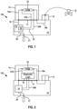
- Figure 1 illustrates a first embodiment single-field device I/O connector 100.
- the field device I/O connector includes a base 10 having a set of electrical connectors that land the field wires of a field device D.
- the set of electrical connectors is formed as a terminal block that includes a set of terminals 12.
- the terminal block can be configured as needed for the number of field wires from the field device and the type of termination desired for the field wires.
- the terminals of the terminal block 12 and the base define a base I/O channel portion 16b.
- the I/O module includes a module I/O channel portion 16m.
- the base I/O channel portion and the module I/O channel portion are electrically connected together by a pair 17 of male and female cooperating electrical connectors (one electrical connector fixedly attached to the I/O module, the other electrical connector fixedly attached to the base).
- the pair 17 of electrical connectors electrically connect the base and module I/O channel portions together to cooperatively define an I/O channel 16.
- the I/O channel includes a conversion circuit described in more detail below.
- the illustrated I/O channel 16 is part of a signal processing circuit 18 disposed in the base that includes the conversion circuit. In other possible embodiments the I/O channel 16 extends away from the base to a conversion circuit not disposed on the base.
- a digital data circuit 20 extends from the signal processing circuit 18 to a network port 21.
- the digital data circuit and the network port cooperate to transfer digital data from the signal processing circuit out of the field device I/O connector to the process control network and to transfer digital data received from the process control network to the signal processing circuit.
- the network port is compatible with the physical layer of the process control network and in embodiments may be a jack (for example, an RJ45 jack), a set of terminals, a communications bus, a cable socket, part of a backplane, or the like.
- the data transferred to the signal processing circuit can include commands to set the operating mode of the conversion circuit as required by the type of field device D.
- the illustrated I/O module 14 inserts an ancillary formed as a fuse 22 in the signal path of the I/O channel 16.
- the I/O module 14 also includes a portion 24A of a diagnostic circuit that is connected to the I/O channel across the fuse. The diagnostic circuit monitors the state of the fuse (fuse open, fuse closed, or the like).
- the module diagnostic circuit portion 24A When the I/O module 14 is plugged into the base 10, the module diagnostic circuit portion 24A connects with a base diagnostic circuit portion 24B carried in the base through the pair 17 of cooperating male and female electrical connectors to define a diagnostic circuit 24 operable to monitor the state of the fuse.
- the diagnostic circuit 24 does not affect the signal traveling through the I/O channel 16 (much like a voltmeter does not significantly affect the voltage drop of a circuit or an ammeter does not significantly affect current flow through a circuit).
- the diagnostic circuit 24 is connected to a diagnostic logic circuit 19 forming part of the signal processing circuit 18.
- the diagnostic logic circuit extracts diagnostic data from the diagnostic circuit and formats the diagnostic data in a digital data format.
- the diagnostic data is output from the field device I/O connector through the network port 21.
- An I/O module like the I/O module M shown in Figure 6 that lacks a diagnostic circuit can perform properly when connected to the base 10 but would not provide diagnostic data.
- Figure 2 illustrates a second embodiment single-field device I/O connector 102 similar to the field device I/O connector 100.
- the diagnostic logic circuit 19 is carried in the I/O module 14.
- the module diagnostic circuit portion 24A includes a portion extending from the module I/O channel portion 16m to the diagnostic logic circuit 19, and a portion extending from the diagnostic logic circuit for transmitting the diagnostic data extracted by the diagnostic logic circuit out of the I/O module.
- the base diagnostic circuit portion 24B is configured to receive the diagnostic data from the I/O module and transmit the diagnostic data to the signal processing circuit 18 for output through the network port 21.
- control system can communicate with the diagnostic logic circuit 19 through the network port 21 if the signal processing circuit 18 and diagnostic logic circuit are configured for two-way communication represented by the double arrow shown in Figure 1 and in Figure 2 . This enables the control system to change acceptable parameters, reset accumulated values, or otherwise set or modify values stored or used by the diagnostic logic circuit.
- Figure 3 illustrates a multi-field device I/O connector 104 configured to attach the field wires of up to four field devices (not shown) to the connector.
- Other embodiments of a multi-field device I/O connector may be configured to attach up to two, three, or more than four field devices.
- the base 10 includes multiple sets of electrical connectors formed as a terminal block having four sets of terminals 12 configured to connect the field wires of the field devices to the multi-field I/O connector.
- the base and the sets of terminals define four like base I/O channel portions 16b.
- the multi-field device I/O connector carries up to four removable I/O modules 14 of the kind described above, each I/O module including a module I/O channel portion 16m.
- the base and the I/O modules form respective I/O channels 16 that each include a signal processing circuit 18 as previously described with respect to the I/O channel of the single-field device I/O connector.
- the four signal processing circuits 18 are connected to a common communication circuit 212 that handles data transmission between the digital data circuit 20 and the signal processing circuits.
- Each I/O channel is associated with a respective diagnostic circuit 24 that monitors the module I/O channel portion as previously described for the single-field device I/O connector.
- Each diagnostic circuit may include a diagnostic logic circuit formed as part of the signal processing circuit of the I/O channel or in the I/O module as previously described.
- each diagnostic circuit 24 is connected to the signal processing circuit 18 associated with its I/O module.
- a diagnostic data output circuit similar to the diagnostic data output circuit 26 shown in Figure 2 is associated with each I/O module and connects the logic diagnostic circuit in the I/O module with the signal processing circuit.
- FIG. 4 Yet another possible embodiment of a field device I/O connector 106 is shown in Figure 4 and is similar to the field device I/O connector 102 shown in Figure 2 .
- the diagnostic circuit 24 connects to its own separate, dedicated output port 108 of the field device I/O connector.
- the output port in embodiments may be realized as a jack, communications bus, cable socket, or the like and is intended to connect the diagnostic circuit to a diagnostic logic circuit remote from the field device I/O connector.
- Figures 1-4 a pair of cooperating electrical connectors electrically connect the base 10 and an I/O module 14.
- Figure 5 illustrates a portion of a field device I/O connector 110 similar to the field device I/O connector 100 but has the I/O channel circuit portions connected by a first pair 17a of male and female electrical connectors and the diagnostic circuit portions connected by a second pair 17b of male and female electrical connectors.
- I/O modules without a diagnostic circuit can include a dummy male or female electrical connector to form the pair 17b of electrical connectors.
- circuits shown in the drawings are drawn as single lines to simplify the drawings and can represent multiple-wire or multiple-line circuit paths as understood in the art.
Landscapes
- Engineering & Computer Science (AREA)
- Automation & Control Theory (AREA)
- Microelectronics & Electronic Packaging (AREA)
- Physics & Mathematics (AREA)
- General Physics & Mathematics (AREA)
- Programmable Controllers (AREA)
Description
- The field of the present invention relates generally to process control systems utilizing field devices and process control networks, and more particularly, to a field device I/O connector for connecting a field device to a process control network.
- Process control networks transmit I/O signals to and from field devices under the control of a control system that regulates and controls industrial processes. Field devices include sensors and actuators. Sensors transmit input signals representing the state of process variables to the controllers, and actuators receive output signals from the controllers and take action to affect process variables.
- I/O signals may be analog signals or digital signals. Analog I/O signals are variable, in which a voltage or current represents the magnitude of a process parameter such as flow rate or the desired position of a valve. Digital I/O signals represent one of two states: "on/off', "opened/closed", and the like.
- Digital signals used in process control are also used to actuate a relay or to count pulses.
- Sophisticated industrial processes may use a number of field devices distributed over a wide area for process control. I/O field wiring from the field devices is often brought to a central location for ease of management. The field wiring may extend to sets of terminals of a terminal block contained in a wiring cabinet. A circuit (referred to as an I/O channel herein) includes the set of terminals and includes a conversion circuit that ultimately is connected to the control system. The conversion circuit converts between I/O signals compatible with the field device and a digital data format.
- Fixed-mode conversion circuits convert between one type of I/O signal and the digital data format.
- Selectable-mode conversion circuits allow different types of field devices to be connected to each set of terminals of the terminal block.
-
Brodbeck, et al. US Patent 9,971,727 -
Figure 6 illustrates a field device I/O connector A for connecting a field device to a process control network N. The field device I/O connector is shown attached to the field wires of a field device D and transceives I/O signals to and from the field device. The field device I/O connector includes a base B having a set of terminals T and a removable I/O module M. The base defines a base I/O channel portion Cb. The I/O module includes a module I/O channel portion Cm. When the I/O module is plugged into the base, connector halves of an electrical connector S electrically connect the base I/O channel portion and the module I/O channel portion to form part of an I/O channel C. The I/O channel includes a conversion circuit V that converts between I/O signals compatible with the field device and a digital data format of the process control network. A network port P connects the field device I/O connector to the process control network and sends and receives digital data to and from the network. -
US 20100077111 A1 discloses a removable communication module connected with the internal bus of a field device that may include diagnostic software to gather information about the field device. It further teaches that the diagnostic software is operatively connected to the internal bus of the field device to enable collecting the diagnostic information. -
Isenmann et al. US 200070243838 A1 -
Endress & Hauser GmbH WO 2004099889 A1 discloses an adapter unit that attaches to a non-fieldbus capable field device and connects the non-fieldbus capable field device to a field bus. The adapter unit attaches to a diagnostics/service interface of the field device to transmit diagnostics/service data through the connected fieldbus. - It is desired to provide a field device I/O connector having a removable I/O module module attached to a base wherein the base can provide diagnostic information concerning operation or operating history of the I/O channel associated with the I/O module, the ancillary inserted in the I/O channel by the I/O module, or the field device attached to the I/O channel.
- The present invention is defined in the independent claim 1.
Disclosed is a field device I/O connector having a removable I/O module that provides diagnostic information concerning operation or operating history of the I/O channel associated with the I/O module, the ancillary inserted in the I/O channel by the I/O module, or the field device attached to the I/O channel. - An embodiment of a field device I/O connector in accordance with this disclosure includes a base and a removable I/O module attached to the base for transmitting I/O signals along an I/O channel. The base includes a set of one or more electrical connectors that connect the base to the field wires of a field device. The set of electrical connectors can be formed in a possible embodiment as a set of one or more terminals that connect the base to the field wires of a field device. The set of electrical connectors can be adapted to conform to the number of field wires of the field device and the desired type of termination of the field wires.
- The base defines a base I/O channel portion that includes the set of electrical connectors. The I/O module includes a module I/O channel portion. When the I/O module is attached to the base, the base and I/O module I/O channel portions are electrically connected together and define part of an I/O channel.
- The I/O channel includes a conversion circuit. The conversion circuit may be a fixed-mode conversion circuit or a selectable-mode conversion circuit. Examples of selectable-mode conversion circuits that can be adapted for use with the disclosed I/O field device connection include, but are not limited to, those provided by the commercially available ANALOG DEVICES AD74412R or AD74413R signal processing integrated circuit (Analog Devices, Inc., One Technology Way, Norwood Massachusetts 02062-9106 USA). The conversion circuit is connected to a network port on the base that transmits digital data between the field device I/O connector and the process control network.
- The I/O module enables signal processing of the I/O signal, supplying power to the field device, interposing fuses or other ancillaries in the signal path, and other functions as disclosed in the '727 patent. In other possible embodiments the I/O module can provide pre commission connection to an attached field device for validating the field device installation during construction of the process control network.
- When the I/O module is attached to the base, the I/O module and the base also cooperatively define a diagnostic circuit connected to the module I/O channel portion. The diagnostic circuit in embodiments provides diagnostic information concerning operation or operating history of the I/O channel associated with the I/O module, an ancillary inserted in the I/O channel by the I/O module, the field device attached to the I/O channel, or perform some other diagnostic function.
- In possible embodiments, the base is configured with multiple sets of electrical connectors to connect to multiple field devices at one time. The multiple sets of electrical connectors in a possible embodiment are formed as a terminal block having multiple sets of terminals for landing field wires of the multiple field devices. Multiple respective base I/O channel portions extend from the sets of terminals of the terminal block. Each base I/O channel portion removably attaches an I/O module to the base to form part of an I/O channel.
- The base of the I/O module includes a diagnostic logic circuit that monitors the diagnostic circuit, performs the diagnostic logic to generate diagnostic data, and transmits the diagnostic data output to an output. Having the diagnostic logic circuit in the base enables customization of the diagnostic logic circuit for the specific configuration of the I/O module or the type of field device the I/O module will be attached to.
- In other embodiments the diagnostic logic circuit is outside of the I/O module and may be located on the base or remote from the base.
- The digital data output from the base in embodiments of the disclosed field device I/O connector includes both digitized I/O signal data from each field device attached to the field device I/O connector and diagnostic data generated from each I/O module attached to the base of the field device I/O connector.
- Other objects and features of the disclosure will become apparent as the description proceeds, especially when taken in conjunction with the accompanying drawing sheets illustrating one or more non-limiting embodiments.
-
-
Figure 1 is a schematic side view of a first embodiment single-field device I/O connector in accordance with this disclosure. -
Figure 2 is similar toFigure 1 but of a second embodiment single-field device I/O connector in accordance with this disclosure. -
Figure 3 is a schematic diagram of a multi-field device I/O connector in accordance with this disclosure. -
Figure 4 is a schematic top view of a portion of a fourth embodiment field device I/O connector in accordance with this disclosure. -
Figure 5 is a schematic side view of a portion of a fifth embodiment field device I/O connector in accordance with this disclosure. -
Figure 6 is a schematic side view of a field device I/O connector of the type disclosed in the '727 patent. -
Figure 1 illustrates a first embodiment single-field device I/O connector 100. The field device I/O connector includes a base 10 having a set of electrical connectors that land the field wires of a field device D. The set of electrical connectors is formed as a terminal block that includes a set ofterminals 12. The terminal block can be configured as needed for the number of field wires from the field device and the type of termination desired for the field wires. - Removably mounted on the
base 10 is an I/O module 14. The terminals of theterminal block 12 and the base define a base I/O channel portion 16b. The I/O module includes a module I/O channel portion 16m. - When the I/O module is mounted to the base, the base I/O channel portion and the module I/O channel portion are electrically connected together by a
pair 17 of male and female cooperating electrical connectors (one electrical connector fixedly attached to the I/O module, the other electrical connector fixedly attached to the base). Thepair 17 of electrical connectors electrically connect the base and module I/O channel portions together to cooperatively define an I/O channel 16. - The I/O channel includes a conversion circuit described in more detail below. The illustrated I/
O channel 16 is part of asignal processing circuit 18 disposed in the base that includes the conversion circuit. In other possible embodiments the I/O channel 16 extends away from the base to a conversion circuit not disposed on the base. - A
digital data circuit 20 extends from thesignal processing circuit 18 to anetwork port 21. The digital data circuit and the network port cooperate to transfer digital data from the signal processing circuit out of the field device I/O connector to the process control network and to transfer digital data received from the process control network to the signal processing circuit. The network port is compatible with the physical layer of the process control network and in embodiments may be a jack (for example, an RJ45 jack), a set of terminals, a communications bus, a cable socket, part of a backplane, or the like. - If the conversion circuit is a selectable-mode conversion circuit, the data transferred to the signal processing circuit can include commands to set the operating mode of the conversion circuit as required by the type of field device D.
- The illustrated I/
O module 14 inserts an ancillary formed as afuse 22 in the signal path of the I/O channel 16. The I/O module 14 also includes aportion 24A of a diagnostic circuit that is connected to the I/O channel across the fuse. The diagnostic circuit monitors the state of the fuse (fuse open, fuse closed, or the like). - When the I/
O module 14 is plugged into thebase 10, the modulediagnostic circuit portion 24A connects with a basediagnostic circuit portion 24B carried in the base through thepair 17 of cooperating male and female electrical connectors to define adiagnostic circuit 24 operable to monitor the state of the fuse. Thediagnostic circuit 24 does not affect the signal traveling through the I/O channel 16 (much like a voltmeter does not significantly affect the voltage drop of a circuit or an ammeter does not significantly affect current flow through a circuit). - In the illustrated embodiment the
diagnostic circuit 24 is connected to adiagnostic logic circuit 19 forming part of thesignal processing circuit 18. The diagnostic logic circuit extracts diagnostic data from the diagnostic circuit and formats the diagnostic data in a digital data format. The diagnostic data is output from the field device I/O connector through thenetwork port 21. - An I/O module like the I/O module M shown in
Figure 6 that lacks a diagnostic circuit can perform properly when connected to the base 10 but would not provide diagnostic data. -
Figure 2 illustrates a second embodiment single-field device I/O connector 102 similar to the field device I/O connector 100. In this embodiment thediagnostic logic circuit 19 is carried in the I/O module 14. The modulediagnostic circuit portion 24A includes a portion extending from the module I/O channel portion 16m to thediagnostic logic circuit 19, and a portion extending from the diagnostic logic circuit for transmitting the diagnostic data extracted by the diagnostic logic circuit out of the I/O module. The basediagnostic circuit portion 24B is configured to receive the diagnostic data from the I/O module and transmit the diagnostic data to thesignal processing circuit 18 for output through thenetwork port 21. - In both of the embodiments shown in
Figures 1 and 2 , the control system can communicate with thediagnostic logic circuit 19 through thenetwork port 21 if thesignal processing circuit 18 and diagnostic logic circuit are configured for two-way communication represented by the double arrow shown inFigure 1 and inFigure 2 . This enables the control system to change acceptable parameters, reset accumulated values, or otherwise set or modify values stored or used by the diagnostic logic circuit. -
Figure 3 illustrates a multi-field device I/O connector 104 configured to attach the field wires of up to four field devices (not shown) to the connector. Other embodiments of a multi-field device I/O connector may be configured to attach up to two, three, or more than four field devices. - The
base 10 includes multiple sets of electrical connectors formed as a terminal block having four sets ofterminals 12 configured to connect the field wires of the field devices to the multi-field I/O connector. The base and the sets of terminals define four like base I/O channel portions 16b. The multi-field device I/O connector carries up to four removable I/O modules 14 of the kind described above, each I/O module including a module I/O channel portion 16m. The base and the I/O modules form respective I/O channels 16 that each include asignal processing circuit 18 as previously described with respect to the I/O channel of the single-field device I/O connector. - The four
signal processing circuits 18 are connected to acommon communication circuit 212 that handles data transmission between thedigital data circuit 20 and the signal processing circuits. Each I/O channel is associated with a respectivediagnostic circuit 24 that monitors the module I/O channel portion as previously described for the single-field device I/O connector. Each diagnostic circuit may include a diagnostic logic circuit formed as part of the signal processing circuit of the I/O channel or in the I/O module as previously described. - In
Figure 3 eachdiagnostic circuit 24 is connected to thesignal processing circuit 18 associated with its I/O module. In other embodiments with diagnostic logic circuits disposed in the I/O modules, a diagnostic data output circuit similar to the diagnostic data output circuit 26 shown inFigure 2 is associated with each I/O module and connects the logic diagnostic circuit in the I/O module with the signal processing circuit. - Yet another possible embodiment of a field device I/
O connector 106 is shown inFigure 4 and is similar to the field device I/O connector 102 shown inFigure 2 . In this embodiment, however, thediagnostic circuit 24 connects to its own separate,dedicated output port 108 of the field device I/O connector. The output port in embodiments may be realized as a jack, communications bus, cable socket, or the like and is intended to connect the diagnostic circuit to a diagnostic logic circuit remote from the field device I/O connector. - In
Figures 1-4 , a pair of cooperating electrical connectors electrically connect thebase 10 and an I/O module 14.Figure 5 illustrates a portion of a field device I/O connector 110 similar to the field device I/O connector 100 but has the I/O channel circuit portions connected by afirst pair 17a of male and female electrical connectors and the diagnostic circuit portions connected by asecond pair 17b of male and female electrical connectors. I/O modules without a diagnostic circuit can include a dummy male or female electrical connector to form thepair 17b of electrical connectors. - Some of the circuits shown in the drawings are drawn as single lines to simplify the drawings and can represent multiple-wire or multiple-line circuit paths as understood in the art.
- Other examples of electrical connectors that can be used to land wires of a field device in embodiments of single-field device I/O connectors or multi-field device I/O connectors in accordance with this disclosure include, but are not limited to, pluggable wire connectors in which the wires terminate on the electrical connectors, fixed terminals in which the wires enter terminals fixed directly on the base, electrical connectors that are removably mounted on the base to enable mechanical and/or electrical disconnection of the electrical connectors from the base without disturbing field wire attachments to the electrical connectors, male or female electrical connectors that mate with corresponding female or male electrical connectors attached to and forming part of individual field wires, cable connectors for connecting a cable containing the field wires extending from the field device, and the like.
Claims (7)
- A field device I/O connector for connecting a field device to a process control network, the field device I/O connector comprising:a base (10) and an I/O module (14) removably attached to the base;a set of electrical connectors mounted on the base, the set of electrical connectors being connectable with field wires extending from the field device to carry I/O signals between the field device I/O connector and the field device, the set of electrical connectors comprising one or more electrical connectors;the set of electrical connectors and the base defining a base I/O channel portion (16b) extending from the set of electrical connectors, and the I/O module comprising a module I/O channel portion (16m), the base I/O channel portion and the module I/O channel portion being electrically connected to one another and together forming an I/O channel (16) when the I/O module is attached to the base, the base I/O channel portion comprising a conversion circuit (18) being configured to convert between I/O signals and signals utilizing a digital data format used by the process control network; andthe base comprising a digital data circuit (20) and a network port (21), the digital data circuit connected to the base I/O channel portion and being configured to transfer digital data received from the conversion circuit to the network port, the network port being configured to be attachable to the process control network and to transmit data received from the digital data circuit to the process control network when the network port is attached to the process control network;characterized bythe base and the I/O module cooperatively defining a diagnostic circuit (24) electrically connected to the module I/O channel portion, the diagnostic circuit being configured to generate diagnostic data concerning the operating state or operational history of the I/O channel, I/O channel circuit components, or the field device attached to the I/O channel when the field device I/O connector is connecting the field device to the process control network;the diagnostic circuit being connected to a diagnostic logic circuit (19) being configured to extract the diagnostic data in a digital data format from the diagnostic circuit;the digital data circuit being connected to the diagnostic logic circuit and being configured to transfer the diagnostic data extracted by the diagnostic logic circuit to the network port; andthe base comprising the diagnostic logic circuit.
- The field device I/O connector of claim 1 wherein a signal processing circuit includes the conversion circuit and the diagnostic logic circuit, the signal processing circuit being configured to transmit digital data from the conversion circuit and diagnostic data output from the diagnostic logic circuit to the digital data circuit.
- The field device I/O connector of claim 1 wherein the network port is a first_network port and the diagnostic circuit extends to a second network port that operates independently of the first network port.
- The field device I/O connector of claim 1 wherein the digital data circuit is configured to receive data from the network port in a digital format and transmit the received data to the conversion circuit for conversion into I/O signals.
- The field device I/O connector of claim 1 wherein the I/O module interposes an ancillary (22) in the I/O channel and the diagnostic circuit is configured to monitor the state or operation of the ancillary.
- The field device I/O connector of claim 1 wherein the ancillary is one of the following: a fuse, a relay, and a manually operated disconnect.
- The field device I/O connector of claim 1 being a multi-field device I/O connector wherein the base I/O channel portion is a first base I/O channel portion of a plurality of like base I/O channel portions, the I/O module is a first I/O module of a plurality of I/O modules attached to the base, each base I/O channel portion of the plurality of base I/O channel portions cooperates with a respective I/O module of the plurality of I/O modules in defining a respective I/O channel, and a respective diagnostic circuit connected to the module I/O channel portion of the respective I/O module.
Applications Claiming Priority (2)
| Application Number | Priority Date | Filing Date | Title |
|---|---|---|---|
| US16/710,767 US11197386B2 (en) | 2019-12-11 | 2019-12-11 | Removable I/O module with diagnostics for a field device I/O connector |
| PCT/US2020/052087 WO2021118674A1 (en) | 2019-12-11 | 2020-09-23 | Removable i/o module with diagnostics for a field device i/o connector |
Publications (2)
| Publication Number | Publication Date |
|---|---|
| EP4062241A1 EP4062241A1 (en) | 2022-09-28 |
| EP4062241B1 true EP4062241B1 (en) | 2025-02-26 |
Family
ID=72752542
Family Applications (1)
| Application Number | Title | Priority Date | Filing Date |
|---|---|---|---|
| EP20786403.4A Active EP4062241B1 (en) | 2019-12-11 | 2020-09-23 | Removable i/o module with diagnostics for a field device i/o connector |
Country Status (4)
| Country | Link |
|---|---|
| US (1) | US11197386B2 (en) |
| EP (1) | EP4062241B1 (en) |
| CN (1) | CN114787728A (en) |
| WO (1) | WO2021118674A1 (en) |
Families Citing this family (2)
| Publication number | Priority date | Publication date | Assignee | Title |
|---|---|---|---|---|
| US11500347B2 (en) * | 2019-12-11 | 2022-11-15 | Phoenix Contact Development and Manufacturing, Inc. | I/O network module with unique network address |
| EP4568210A3 (en) * | 2021-02-23 | 2025-07-23 | Phoenix Contact Development and Manufacturing, Inc. | Apl field switch with automatic protocol detection |
Family Cites Families (15)
| Publication number | Priority date | Publication date | Assignee | Title |
|---|---|---|---|---|
| US6175932B1 (en) * | 1998-04-20 | 2001-01-16 | National Instruments Corporation | System and method for providing state capture and restoration to an I/O system |
| WO2004009889A1 (en) | 2002-07-24 | 2004-01-29 | Teijin Fibers Limited | Flat multifilament-yarn textile |
| WO2004099889A1 (en) * | 2003-05-09 | 2004-11-18 | Endress + Hauser Gmbh+Co. Kg | Adapter unit for field bus communication |
| WO2007118656A1 (en) | 2006-04-12 | 2007-10-25 | Vega Grieshaber Kg | Transceiver for wire-free transmission of field device signals |
| US9083548B2 (en) | 2008-09-23 | 2015-07-14 | Fisher-Rosemount Systems, Inc. | Apparatus and methods to communicatively couple field devices to controllers in a process control system |
| GB0903836D0 (en) * | 2009-03-05 | 2009-04-22 | Oxford Instr Plasma Technology | Interface module and controller network |
| JP5904190B2 (en) | 2013-10-31 | 2016-04-13 | 横河電機株式会社 | I/O Module |
| JP6090127B2 (en) * | 2013-11-21 | 2017-03-08 | ソニー株式会社 | Optical communication device, transmission device, reception device, and transmission / reception system |
| US10248601B2 (en) * | 2014-03-27 | 2019-04-02 | Honeywell International Inc. | Remote terminal unit (RTU) with universal input/output (UIO) and related method |
| US9971727B2 (en) | 2014-06-02 | 2018-05-15 | Phoenix Contact Development and Manufacturing, Inc. | Universal I/O signal interposer system |
| GB2535839B (en) * | 2015-01-08 | 2021-06-09 | Fisher Rosemount Systems Inc | Apparatus and methods to communicatively couple field devices to controllers in a process control system |
| US10360125B2 (en) * | 2016-05-31 | 2019-07-23 | Bristol, Inc. | Methods and apparatus to communicatively couple field devices to a remote terminal unit |
| US10845773B2 (en) * | 2019-02-22 | 2020-11-24 | Abb Schweiz Ag | Selector for field devices |
| US11412632B2 (en) * | 2019-06-11 | 2022-08-09 | Rockwell Automation Asia Pacific Business Center Pte. Ltd. | Isolated power smart terminal block |
| LU101568B1 (en) * | 2019-10-29 | 2021-04-29 | Phoenix Contact Gmbh & Co | Interface arrangement for connecting at least one control device to a plurality of field devices |
-
2019
- 2019-12-11 US US16/710,767 patent/US11197386B2/en active Active
-
2020
- 2020-09-23 WO PCT/US2020/052087 patent/WO2021118674A1/en not_active Ceased
- 2020-09-23 EP EP20786403.4A patent/EP4062241B1/en active Active
- 2020-09-23 CN CN202080086044.4A patent/CN114787728A/en active Pending
Also Published As
| Publication number | Publication date |
|---|---|
| WO2021118674A1 (en) | 2021-06-17 |
| US11197386B2 (en) | 2021-12-07 |
| US20210185846A1 (en) | 2021-06-17 |
| CN114787728A (en) | 2022-07-22 |
| EP4062241A1 (en) | 2022-09-28 |
Similar Documents
| Publication | Publication Date | Title |
|---|---|---|
| EP1571510B1 (en) | Intelligent self-determining I/O device | |
| CN106462131B (en) | Universal I/O Signal Inserter System | |
| US9544165B2 (en) | Data transmission device for remote monitoring and remote controlling in a distributed process system | |
| US9966714B1 (en) | I/O migration adapter for control system | |
| US11815871B2 (en) | I/O network module with unique network address | |
| CN103428005A (en) | Interface module with power over ethernet function | |
| JP2009535877A (en) | Assembly to enable power-over-Ethernet connection | |
| GB2594207A (en) | Apparatus to communicatively couple three-wire field devices to controllers in a process control system | |
| KR20090077761A (en) | MV or HV distribution cubicles with integrated digital communication and multifunctional modules for these cubicles | |
| US11197386B2 (en) | Removable I/O module with diagnostics for a field device I/O connector | |
| US20090136293A1 (en) | Two wire signal over power work tool coupling and identification | |
| CN102970335B (en) | Communication system | |
| WO2009134222A1 (en) | System and method for efficient association of a power outlet and device | |
| US20060234526A1 (en) | Automation system | |
| DE10131094B4 (en) | Intrinsically safe coupler module for connection to a data network | |
| EP1895754A2 (en) | General purpose physical data transmission port | |
| US11093428B2 (en) | Convertible I/O signal processor for a process control network | |
| CN116031998A (en) | Distributed substation terminal based on multiport forwarding communication | |
| CN223714110U (en) | Communication terminal of power distribution network | |
| CN220628433U (en) | Connection assembly and vehicle-mounted network data acquisition system | |
| EP4730060A1 (en) | Bridging device for extracting information from field devices | |
| CN101120291A (en) | Medium or high voltage switchgear comprising at least one switchgear | |
| KR101821710B1 (en) | Power device communication connecting system | |
| SK131099A3 (en) | Interface device for an electrical safety relay in a process control system and installation equipped with such a device | |
| JPS62221234A (en) | Line converter |
Legal Events
| Date | Code | Title | Description |
|---|---|---|---|
| STAA | Information on the status of an ep patent application or granted ep patent |
Free format text: STATUS: UNKNOWN |
|
| STAA | Information on the status of an ep patent application or granted ep patent |
Free format text: STATUS: THE INTERNATIONAL PUBLICATION HAS BEEN MADE |
|
| PUAI | Public reference made under article 153(3) epc to a published international application that has entered the european phase |
Free format text: ORIGINAL CODE: 0009012 |
|
| STAA | Information on the status of an ep patent application or granted ep patent |
Free format text: STATUS: REQUEST FOR EXAMINATION WAS MADE |
|
| 17P | Request for examination filed |
Effective date: 20220624 |
|
| AK | Designated contracting states |
Kind code of ref document: A1 Designated state(s): AL AT BE BG CH CY CZ DE DK EE ES FI FR GB GR HR HU IE IS IT LI LT LU LV MC MK MT NL NO PL PT RO RS SE SI SK SM TR |
|
| DAV | Request for validation of the european patent (deleted) | ||
| DAX | Request for extension of the european patent (deleted) | ||
| STAA | Information on the status of an ep patent application or granted ep patent |
Free format text: STATUS: EXAMINATION IS IN PROGRESS |
|
| 17Q | First examination report despatched |
Effective date: 20230403 |
|
| P01 | Opt-out of the competence of the unified patent court (upc) registered |
Effective date: 20230525 |
|
| P02 | Opt-out of the competence of the unified patent court (upc) changed |
Effective date: 20230531 |
|
| GRAP | Despatch of communication of intention to grant a patent |
Free format text: ORIGINAL CODE: EPIDOSNIGR1 |
|
| STAA | Information on the status of an ep patent application or granted ep patent |
Free format text: STATUS: GRANT OF PATENT IS INTENDED |
|
| INTG | Intention to grant announced |
Effective date: 20241031 |
|
| GRAS | Grant fee paid |
Free format text: ORIGINAL CODE: EPIDOSNIGR3 |
|
| GRAA | (expected) grant |
Free format text: ORIGINAL CODE: 0009210 |
|
| STAA | Information on the status of an ep patent application or granted ep patent |
Free format text: STATUS: THE PATENT HAS BEEN GRANTED |
|
| AK | Designated contracting states |
Kind code of ref document: B1 Designated state(s): AL AT BE BG CH CY CZ DE DK EE ES FI FR GB GR HR HU IE IS IT LI LT LU LV MC MK MT NL NO PL PT RO RS SE SI SK SM TR |
|
| REG | Reference to a national code |
Ref country code: GB Ref legal event code: FG4D |
|
| REG | Reference to a national code |
Ref country code: CH Ref legal event code: EP |
|
| REG | Reference to a national code |
Ref country code: DE Ref legal event code: R096 Ref document number: 602020046828 Country of ref document: DE |
|
| REG | Reference to a national code |
Ref country code: IE Ref legal event code: FG4D |
|
| REG | Reference to a national code |
Ref country code: NL Ref legal event code: MP Effective date: 20250226 |
|
| PG25 | Lapsed in a contracting state [announced via postgrant information from national office to epo] |
Ref country code: RS Free format text: LAPSE BECAUSE OF FAILURE TO SUBMIT A TRANSLATION OF THE DESCRIPTION OR TO PAY THE FEE WITHIN THE PRESCRIBED TIME-LIMIT Effective date: 20250526 |
|
| PG25 | Lapsed in a contracting state [announced via postgrant information from national office to epo] |
Ref country code: FI Free format text: LAPSE BECAUSE OF FAILURE TO SUBMIT A TRANSLATION OF THE DESCRIPTION OR TO PAY THE FEE WITHIN THE PRESCRIBED TIME-LIMIT Effective date: 20250226 |
|
| PG25 | Lapsed in a contracting state [announced via postgrant information from national office to epo] |
Ref country code: PL Free format text: LAPSE BECAUSE OF FAILURE TO SUBMIT A TRANSLATION OF THE DESCRIPTION OR TO PAY THE FEE WITHIN THE PRESCRIBED TIME-LIMIT Effective date: 20250226 |
|
| PG25 | Lapsed in a contracting state [announced via postgrant information from national office to epo] |
Ref country code: ES Free format text: LAPSE BECAUSE OF FAILURE TO SUBMIT A TRANSLATION OF THE DESCRIPTION OR TO PAY THE FEE WITHIN THE PRESCRIBED TIME-LIMIT Effective date: 20250226 |
|
| REG | Reference to a national code |
Ref country code: LT Ref legal event code: MG9D |
|
| PG25 | Lapsed in a contracting state [announced via postgrant information from national office to epo] |
Ref country code: NO Free format text: LAPSE BECAUSE OF FAILURE TO SUBMIT A TRANSLATION OF THE DESCRIPTION OR TO PAY THE FEE WITHIN THE PRESCRIBED TIME-LIMIT Effective date: 20250526 Ref country code: IS Free format text: LAPSE BECAUSE OF FAILURE TO SUBMIT A TRANSLATION OF THE DESCRIPTION OR TO PAY THE FEE WITHIN THE PRESCRIBED TIME-LIMIT Effective date: 20250626 |
|
| PG25 | Lapsed in a contracting state [announced via postgrant information from national office to epo] |
Ref country code: NL Free format text: LAPSE BECAUSE OF FAILURE TO SUBMIT A TRANSLATION OF THE DESCRIPTION OR TO PAY THE FEE WITHIN THE PRESCRIBED TIME-LIMIT Effective date: 20250226 |
|
| PG25 | Lapsed in a contracting state [announced via postgrant information from national office to epo] |
Ref country code: HR Free format text: LAPSE BECAUSE OF FAILURE TO SUBMIT A TRANSLATION OF THE DESCRIPTION OR TO PAY THE FEE WITHIN THE PRESCRIBED TIME-LIMIT Effective date: 20250226 |
|
| PG25 | Lapsed in a contracting state [announced via postgrant information from national office to epo] |
Ref country code: LV Free format text: LAPSE BECAUSE OF FAILURE TO SUBMIT A TRANSLATION OF THE DESCRIPTION OR TO PAY THE FEE WITHIN THE PRESCRIBED TIME-LIMIT Effective date: 20250226 Ref country code: PT Free format text: LAPSE BECAUSE OF FAILURE TO SUBMIT A TRANSLATION OF THE DESCRIPTION OR TO PAY THE FEE WITHIN THE PRESCRIBED TIME-LIMIT Effective date: 20250626 |
|
| PG25 | Lapsed in a contracting state [announced via postgrant information from national office to epo] |
Ref country code: BG Free format text: LAPSE BECAUSE OF FAILURE TO SUBMIT A TRANSLATION OF THE DESCRIPTION OR TO PAY THE FEE WITHIN THE PRESCRIBED TIME-LIMIT Effective date: 20250226 Ref country code: GR Free format text: LAPSE BECAUSE OF FAILURE TO SUBMIT A TRANSLATION OF THE DESCRIPTION OR TO PAY THE FEE WITHIN THE PRESCRIBED TIME-LIMIT Effective date: 20250527 |
|
| REG | Reference to a national code |
Ref country code: AT Ref legal event code: MK05 Ref document number: 1771225 Country of ref document: AT Kind code of ref document: T Effective date: 20250226 |
|
| PG25 | Lapsed in a contracting state [announced via postgrant information from national office to epo] |
Ref country code: SE Free format text: LAPSE BECAUSE OF FAILURE TO SUBMIT A TRANSLATION OF THE DESCRIPTION OR TO PAY THE FEE WITHIN THE PRESCRIBED TIME-LIMIT Effective date: 20250226 |
|
| PG25 | Lapsed in a contracting state [announced via postgrant information from national office to epo] |
Ref country code: SM Free format text: LAPSE BECAUSE OF FAILURE TO SUBMIT A TRANSLATION OF THE DESCRIPTION OR TO PAY THE FEE WITHIN THE PRESCRIBED TIME-LIMIT Effective date: 20250226 |
|
| PG25 | Lapsed in a contracting state [announced via postgrant information from national office to epo] |
Ref country code: DK Free format text: LAPSE BECAUSE OF FAILURE TO SUBMIT A TRANSLATION OF THE DESCRIPTION OR TO PAY THE FEE WITHIN THE PRESCRIBED TIME-LIMIT Effective date: 20250226 |
|
| PGFP | Annual fee paid to national office [announced via postgrant information from national office to epo] |
Ref country code: DE Payment date: 20250919 Year of fee payment: 6 |
|
| PGFP | Annual fee paid to national office [announced via postgrant information from national office to epo] |
Ref country code: IT Payment date: 20250922 Year of fee payment: 6 |
|
| PG25 | Lapsed in a contracting state [announced via postgrant information from national office to epo] |
Ref country code: AT Free format text: LAPSE BECAUSE OF FAILURE TO SUBMIT A TRANSLATION OF THE DESCRIPTION OR TO PAY THE FEE WITHIN THE PRESCRIBED TIME-LIMIT Effective date: 20250226 |
|
| PGFP | Annual fee paid to national office [announced via postgrant information from national office to epo] |
Ref country code: FR Payment date: 20250924 Year of fee payment: 6 |
|
| PG25 | Lapsed in a contracting state [announced via postgrant information from national office to epo] |
Ref country code: EE Free format text: LAPSE BECAUSE OF FAILURE TO SUBMIT A TRANSLATION OF THE DESCRIPTION OR TO PAY THE FEE WITHIN THE PRESCRIBED TIME-LIMIT Effective date: 20250226 Ref country code: CZ Free format text: LAPSE BECAUSE OF FAILURE TO SUBMIT A TRANSLATION OF THE DESCRIPTION OR TO PAY THE FEE WITHIN THE PRESCRIBED TIME-LIMIT Effective date: 20250226 |
|
| PG25 | Lapsed in a contracting state [announced via postgrant information from national office to epo] |
Ref country code: RO Free format text: LAPSE BECAUSE OF FAILURE TO SUBMIT A TRANSLATION OF THE DESCRIPTION OR TO PAY THE FEE WITHIN THE PRESCRIBED TIME-LIMIT Effective date: 20250226 |
|
| PG25 | Lapsed in a contracting state [announced via postgrant information from national office to epo] |
Ref country code: SK Free format text: LAPSE BECAUSE OF FAILURE TO SUBMIT A TRANSLATION OF THE DESCRIPTION OR TO PAY THE FEE WITHIN THE PRESCRIBED TIME-LIMIT Effective date: 20250226 |
|
| REG | Reference to a national code |
Ref country code: DE Ref legal event code: R097 Ref document number: 602020046828 Country of ref document: DE |
|
| PLBE | No opposition filed within time limit |
Free format text: ORIGINAL CODE: 0009261 |
|
| STAA | Information on the status of an ep patent application or granted ep patent |
Free format text: STATUS: NO OPPOSITION FILED WITHIN TIME LIMIT |
|
| REG | Reference to a national code |
Ref country code: CH Ref legal event code: L10 Free format text: ST27 STATUS EVENT CODE: U-0-0-L10-L00 (AS PROVIDED BY THE NATIONAL OFFICE) Effective date: 20260107 |
|
| 26N | No opposition filed |
Effective date: 20251127 |
|
| REG | Reference to a national code |
Ref country code: CH Ref legal event code: H13 Free format text: ST27 STATUS EVENT CODE: U-0-0-H10-H13 (AS PROVIDED BY THE NATIONAL OFFICE) Effective date: 20260504 |