EP4061508B1 - Desulfurization unit, sofc system and vehicle - Google Patents
Desulfurization unit, sofc system and vehicle Download PDFInfo
- Publication number
- EP4061508B1 EP4061508B1 EP20828304.4A EP20828304A EP4061508B1 EP 4061508 B1 EP4061508 B1 EP 4061508B1 EP 20828304 A EP20828304 A EP 20828304A EP 4061508 B1 EP4061508 B1 EP 4061508B1
- Authority
- EP
- European Patent Office
- Prior art keywords
- wall
- bush
- sofc system
- container
- desulfurization unit
- Prior art date
- Legal status (The legal status is an assumption and is not a legal conclusion. Google has not performed a legal analysis and makes no representation as to the accuracy of the status listed.)
- Active
Links
Images
Classifications
-
- H—ELECTRICITY
- H01—ELECTRIC ELEMENTS
- H01M—PROCESSES OR MEANS, e.g. BATTERIES, FOR THE DIRECT CONVERSION OF CHEMICAL ENERGY INTO ELECTRICAL ENERGY
- H01M8/00—Fuel cells; Manufacture thereof
- H01M8/06—Combination of fuel cells with means for production of reactants or for treatment of residues
- H01M8/0662—Treatment of gaseous reactants or gaseous residues, e.g. cleaning
- H01M8/0675—Removal of sulfur
-
- B—PERFORMING OPERATIONS; TRANSPORTING
- B01—PHYSICAL OR CHEMICAL PROCESSES OR APPARATUS IN GENERAL
- B01D—SEPARATION
- B01D53/00—Separation of gases or vapours; Recovering vapours of volatile solvents from gases; Chemical or biological purification of waste gases, e.g. engine exhaust gases, smoke, fumes, flue gases, aerosols
- B01D53/34—Chemical or biological purification of waste gases
- B01D53/46—Removing components of defined structure
- B01D53/48—Sulfur compounds
- B01D53/50—Sulfur oxides
-
- B—PERFORMING OPERATIONS; TRANSPORTING
- B01—PHYSICAL OR CHEMICAL PROCESSES OR APPARATUS IN GENERAL
- B01D—SEPARATION
- B01D53/00—Separation of gases or vapours; Recovering vapours of volatile solvents from gases; Chemical or biological purification of waste gases, e.g. engine exhaust gases, smoke, fumes, flue gases, aerosols
- B01D53/34—Chemical or biological purification of waste gases
- B01D53/46—Removing components of defined structure
- B01D53/48—Sulfur compounds
-
- F—MECHANICAL ENGINEERING; LIGHTING; HEATING; WEAPONS; BLASTING
- F16—ENGINEERING ELEMENTS AND UNITS; GENERAL MEASURES FOR PRODUCING AND MAINTAINING EFFECTIVE FUNCTIONING OF MACHINES OR INSTALLATIONS; THERMAL INSULATION IN GENERAL
- F16B—DEVICES FOR FASTENING OR SECURING CONSTRUCTIONAL ELEMENTS OR MACHINE PARTS TOGETHER, e.g. NAILS, BOLTS, CIRCLIPS, CLAMPS, CLIPS OR WEDGES; JOINTS OR JOINTING
- F16B37/00—Nuts or like thread-engaging members
- F16B37/12—Nuts or like thread-engaging members with thread-engaging surfaces formed by inserted coil-springs, discs, or the like; Independent pieces of wound wire used as nuts; Threaded inserts for holes
- F16B37/122—Threaded inserts, e.g. "rampa bolts"
- F16B37/125—Threaded inserts, e.g. "rampa bolts" the external surface of the insert being threaded
-
- F—MECHANICAL ENGINEERING; LIGHTING; HEATING; WEAPONS; BLASTING
- F16—ENGINEERING ELEMENTS AND UNITS; GENERAL MEASURES FOR PRODUCING AND MAINTAINING EFFECTIVE FUNCTIONING OF MACHINES OR INSTALLATIONS; THERMAL INSULATION IN GENERAL
- F16B—DEVICES FOR FASTENING OR SECURING CONSTRUCTIONAL ELEMENTS OR MACHINE PARTS TOGETHER, e.g. NAILS, BOLTS, CIRCLIPS, CLAMPS, CLIPS OR WEDGES; JOINTS OR JOINTING
- F16B7/00—Connections of rods or tubes, e.g. of non-circular section, mutually, including resilient connections
- F16B7/18—Connections of rods or tubes, e.g. of non-circular section, mutually, including resilient connections using screw-thread elements
- F16B7/182—Connections of rods or tubes, e.g. of non-circular section, mutually, including resilient connections using screw-thread elements for coaxial connections of two rods or tubes
-
- H—ELECTRICITY
- H01—ELECTRIC ELEMENTS
- H01M—PROCESSES OR MEANS, e.g. BATTERIES, FOR THE DIRECT CONVERSION OF CHEMICAL ENERGY INTO ELECTRICAL ENERGY
- H01M8/00—Fuel cells; Manufacture thereof
- H01M8/10—Fuel cells with solid electrolytes
- H01M8/12—Fuel cells with solid electrolytes operating at high temperature, e.g. with stabilised ZrO2 electrolyte
- H01M2008/1293—Fuel cells with solid oxide electrolytes
-
- H—ELECTRICITY
- H01—ELECTRIC ELEMENTS
- H01M—PROCESSES OR MEANS, e.g. BATTERIES, FOR THE DIRECT CONVERSION OF CHEMICAL ENERGY INTO ELECTRICAL ENERGY
- H01M2250/00—Fuel cells for particular applications; Specific features of fuel cell system
- H01M2250/20—Fuel cells in motive systems, e.g. vehicle, ship, plane
-
- Y—GENERAL TAGGING OF NEW TECHNOLOGICAL DEVELOPMENTS; GENERAL TAGGING OF CROSS-SECTIONAL TECHNOLOGIES SPANNING OVER SEVERAL SECTIONS OF THE IPC; TECHNICAL SUBJECTS COVERED BY FORMER USPC CROSS-REFERENCE ART COLLECTIONS [XRACs] AND DIGESTS
- Y02—TECHNOLOGIES OR APPLICATIONS FOR MITIGATION OR ADAPTATION AGAINST CLIMATE CHANGE
- Y02E—REDUCTION OF GREENHOUSE GAS [GHG] EMISSIONS, RELATED TO ENERGY GENERATION, TRANSMISSION OR DISTRIBUTION
- Y02E60/00—Enabling technologies; Technologies with a potential or indirect contribution to GHG emissions mitigation
- Y02E60/30—Hydrogen technology
- Y02E60/50—Fuel cells
-
- Y—GENERAL TAGGING OF NEW TECHNOLOGICAL DEVELOPMENTS; GENERAL TAGGING OF CROSS-SECTIONAL TECHNOLOGIES SPANNING OVER SEVERAL SECTIONS OF THE IPC; TECHNICAL SUBJECTS COVERED BY FORMER USPC CROSS-REFERENCE ART COLLECTIONS [XRACs] AND DIGESTS
- Y02—TECHNOLOGIES OR APPLICATIONS FOR MITIGATION OR ADAPTATION AGAINST CLIMATE CHANGE
- Y02T—CLIMATE CHANGE MITIGATION TECHNOLOGIES RELATED TO TRANSPORTATION
- Y02T90/00—Enabling technologies or technologies with a potential or indirect contribution to GHG emissions mitigation
- Y02T90/40—Application of hydrogen technology to transportation, e.g. using fuel cells
Definitions
- the present invention relates to the technical field of fuel cells and more specifically, relates to a desulfurization unit, an SOFC system and a vehicle.
- a solid oxide fuel cell (SOFC) system is a fuel cell using solid oxide as an electrolyte and working at high temperature.
- the desulfurization unit is a necessary unit, while a conventional desulfurization unit generally is only a container storing a desulfurizing agent or a container integrated with a filter.
- the temperature of the desulfurizing agent is maintained mainly by the temperature of natural gas. This temperature is obtained by heating the natural gas through a thermal cycle of a pressure reducing valve and a heat exchanger.
- This method requires the system to work for a long time in a low temperature environment to reach the temperature required by the desulfurizing agent and shows a low heat exchange efficiency of the desulfurization unit.
- the desulfurization unit in the prior art is large in size and takes up a large space, which is inconvenient for the installation and subsequent maintenance of the unit and the replacement of the desulfurizing agent.
- JP 2015 229742 A discloses a desulfurization unit of a solid oxide fuel cell of a vehicle, comprising a container for holding a desulfurizing agent with inner and outer wall, a cavity formed between the two walls, and an inlet for raw fuel gas and a port.
- the slow temperature rise of the desulfurizing agent in the desulfurization unit of the SOFC system is a problem.
- a first object of the present invention is to provide a desulfurization unit of an SOFC system.
- the structural design of the desulfurization unit of the SOFC system can effectively solve the problem of slow temperature rise of the desulfurizing agent in the desulfurization unit of the SOFC system.
- a second object of the present invention is to provide an SOFC system and a vehicle comprising the foregoing desulfurization unit.
- a first aspect of the invention provides a desulfurization unit of an SOFC system, comprising:
- the bottom of the container can be provided with a grid plate, a buffer cavity is arranged under the grid plate, and the gas entering from the gas inlet flows through the buffer cavity and the grid plate in turn.
- At least one circumferential locating pin can be further provided between the outer bush and the hole wall of the gas outlet.
- the container can be rectangular.
- the water inlet and the water outlet can be located in the upper part and the lower part of the container respectively.
- the adapter can be a right-angle adapter.
- a filter element can be further integrated on the right-angle connector.
- a second aspect of the invention provides an SOFC system comprising at least one of the desulfurization units.
- the SOFC system can comprise a plurality of the desulfurization units, in which any two of the desulfurization units are connected in series or parallel.
- a third aspect of the invention provides vehicle comprising the SOFC system.
- the desulfurization unit of an SOFC system comprises a container and a double threaded bush.
- An inner cavity of the container is used for holding a desulfurizing agent.
- the container comprises an inner wall and an outer wall, a water cavity is formed between the inner wall and the outer wall, and a water inlet and a water outlet in communication with the water cavity are arranged on the outer wall.
- circulating water can enter the water cavity from the water inlet, circulate inside the water cavity and then be discharged out of the water cavity from the water outlet.
- the inner cavity is a cavity on the inner side of the inner wall.
- the desulfurizing agent is kept in the inner cavity.
- the top of the container is provided with a gas outlet, which communicates with the inner cavity.
- the bottom of the container is provided with a gas inlet, which also communicates with the inner cavity. Gas enters the inner cavity from the gas inlet, is desulfurized by the desulfurizing agent and then is discharged from the gas outlet.
- a double threaded bush is arranged at the gas outlet.
- the double threaded bush comprises an inner bush and an outer bush that adopt a nested setting, and threaded connection is adopted between the inner bush and the outer bush, i.e., the outer wall of the inner bush is in screw-thread fit with the inner wall of the outer bush.
- the outer wall of the outer bush is connected to the hole wall of the gas outlet in a threaded manner, and the inner wall of the inner bush is connected to the adapter in a threaded manner.
- the water inlet and water outlet are communicable with the circulating water of the whole vehicle, and the circulating water of the whole vehicle enters the water cavity from the water inlet, circulates in the water cavity and then is discharged out of the water cavity from the water outlet. Further, the circulating water of the whole vehicle heats the desulfurizing agent in the water cavity. In this way, the desulfurizing agent can be heated up once the vehicle is started, and the temperature of the desulfurizing agent can be quickly raised to the operating ambient temperature. This effect is better than a conventional method of heating by gas.
- connection with a double threaded bush has good sealing performance.
- the outer bush and inner bush can be rotated and disassembled together.
- the diameter of the outer bush is larger to facilitate the rapid outflow or inflow of the desulfurizing agent.
- To replace the adapter only rotation of the adapter and the inner bush is needed. This design is not only conducive to frequent adapter replacement without damaging the container, but also conducive to adopting a larger diameter to speed up the replacement of the desulfurizing agent.
- the present invention further provides an SOFC system and a vehicle.
- the SOFC system and the vehicle comprise any of the foregoing desulfurization units.
- the SOFC system and the vehicle comprising the desulfurization unit should also have the corresponding technical effects.
- 1-right-angle adapter 1a-filter element, 2-circumferential locating pin, 3-double threaded bush, 3a-outer bush, 3b-inner bush, 4-water cavity, 5-container, 6-inner cavity, 7-grid plate, 8-circulating water ferrule-type joint, 9-straight adapter.
- An object of the present invention is to provide a desulfurization unit of an SOFC system.
- the structural design of the desulfurization unit of the SOFC system can help solve the problem of slow temperature rise of the desulfurizing agent in the desulfurization unit of the SOFC system.
- a further object of the present invention is to provide an SOFC system and a vehicle comprising the foregoing desulfurization unit.
- the desulfurization unit of the SOFC system comprises a container 5 and a double threaded bush 3.
- An inner cavity 6 of the container 5 is used for holding a desulfurizing agent.
- the container 5 comprises an inner wall and an outer wall, a water cavity 4 is formed between the inner wall and the outer wall, and a water inlet and a water outlet in communication with the water cavity 4 are arranged on the outer wall.
- circulating water can enter the water cavity 4 from the water inlet, circulate inside the water cavity 4 and then be discharged out of the water cavity 4 from the water outlet.
- the inner cavity 6 is a cavity on the inner side of the inner wall.
- the desulfurizing agent is kept in the inner cavity 6.
- the top of the container 5 is provided with a gas outlet, which communicates with the inner cavity 6.
- the bottom of the container 5 is provided with a gas inlet, which also communicates with the inner cavity 6. Gas enters the inner cavity 6 from the gas inlet, is desulfurized by the desulfurizing agent and then is discharged from the gas outlet.
- a double threaded bush 3 is arranged at the gas outlet.
- the double threaded bush 3 comprises an inner bush 3b and an outer bush 3a that adopt a nested setting, and threaded connection is adopted between the inner bush 3b and the outer bush 3a, i.e., the outer wall of the inner bush 3b is in screw-thread fit with the inner wall of the outer bush 3a.
- the outer wall of the outer bush 3a is connected to the hole wall of the gas outlet in a threaded manner, and the inner wall of the inner bush 3b is connected to the adapter in a threaded manner.
- the water inlet and the water outlet are communicable with the circulating water of the whole vehicle, and the circulating water of the whole vehicle enters the water cavity 4 from the water inlet, is circulated in the water cavity 4 and then is discharged out of the water cavity 4 from the water outlet. Further, the circulating water of the whole vehicle heats the desulfurizing agent in the water cavity 4. In this way, the desulfurizing agent can be heated up once the vehicle is started, and the temperature of the desulfurizing agent can be quickly raised to the operating ambient temperature. This effect is better than a conventional method of heating by gas.
- connection with a double threaded bush has good sealing performance.
- the outer bush 3a and inner bush 3b can be rotated and disassembled together.
- the diameter of the outer bush 3a is larger to facilitate the rapid outflow or inflow of the desulfurizing agent.
- To replace the adapter only rotation of the adapter and the inner bush 3b is needed. This design is not only conducive to frequent adapter replacement without damaging the container 5, but also conducive to adopting a larger diameter to speed up the replacement of the desulfurizing agent.
- the bottom of the container 5 can be further provided with a grid plate 7.
- a buffer cavity is arranged under the grid plate 7 and the gas entering from the gas inlet flows through the buffer cavity and the grid plate 7 in turn.
- the grid plate 7 can support the desulfurizing agent and moreover, after the turbulent gas under the grid plate 7 flows through the grid plate 7, the gas is more uniformly distributed.
- a plurality of round through holes or through holes in other shapes can be arranged on the grid plate 7.
- the grid plate 7 can be a grid plate 7 densely perforated by lasers.
- At least one circumferential locating pin 2 can be arranged between the outer bush 3a and the hole wall of the gas outlet.
- the circumferential locating pin 2 can prevent rotation of the outer bush 3a. To replace the desulfurizing agent, only removal of the circumferential locating pin 2 and rotation of the outer bush 3a are needed.
- the circumferential locating pin 2 can pass through a pin hole on the outer bush 3a and be inserted into the pin hole on the hole wall of the gas outlet.
- the container 5 can be rectangular.
- the desulfurization units can be used alone, and a single unit has a small volume and a small weight and facilitates the installation and replacement of the desulfurizing agent.
- a plurality of desulfurization units can be used in a combined manner, and according to different catalysts and use requirements, a different number of desulfurization units are connected in series and quickly assembled to increase the volume of the desulfurizing agent and achieve the desulfurization effect.
- the desulfurization unit can also be fixed on the side wall of the vehicle environment compartment conveniently. Compared with a cylindrical desulfurization tank, the desulfurization unit can effectively utilize the space and save installation space for other systems.
- the water inlet and the water outlet are located in the upper part and the lower part of the container 5 respectively, so as to make the best use of the heat of the circulating water. Further, the water inlet and the water outlet can be arranged on two sides of the container 5. The water inlet is in the lower part of the container 5 and the water outlet is in the upper part of the container 5.
- the water inlet and the water outlet may further be provided with a circulating water ferrule-type joint 8 to facilitate connection to other components.
- a circulating water ferrule-type joint 8 to facilitate connection to other components.
- the foregoing adapter connected to the inner bush 3b can be a right-angle adapter 1, to further facilitate connection to other components.
- a filter element 1a is integrated on the right-angle connector.
- the filter element 1a is a sinter-type filter element to trap particles of size 0.5 ⁇ m and above.
- An adapter is further arranged at the gas inlet.
- the adapter at the gas inlet can be a straight adapter 9.
- a filter element 1a can be integrated on the adapter at the gas inlet, too.
- the adapter at the gas inlet and the adapter connected to the inner bush 3b both can be ferrule-type adapters.
- the present invention further provides an SOFC system.
- the SOFC system comprises any desulfurization unit provided by the foregoing embodiments.
- the SOFC system adopts the desulfurization unit provided by the foregoing embodiments, the beneficial effects of the SOFC system can be seen in the foregoing embodiments.
- the SOFC system comprises a plurality of desulfurization units, and any two of the desulfurization units are connected in series or in parallel.
- a plurality of desulfurization units can be connected in series or in parallel.
- the present invention further provides a vehicle.
- the vehicle comprises the foregoing SOFC system, so the beneficial effects of the vehicle can be seen in the foregoing embodiments.
Landscapes
- Engineering & Computer Science (AREA)
- General Engineering & Computer Science (AREA)
- Chemical & Material Sciences (AREA)
- Mechanical Engineering (AREA)
- General Chemical & Material Sciences (AREA)
- Chemical Kinetics & Catalysis (AREA)
- Manufacturing & Machinery (AREA)
- Sustainable Energy (AREA)
- Sustainable Development (AREA)
- Electrochemistry (AREA)
- Life Sciences & Earth Sciences (AREA)
- Health & Medical Sciences (AREA)
- Biomedical Technology (AREA)
- Environmental & Geological Engineering (AREA)
- Analytical Chemistry (AREA)
- Oil, Petroleum & Natural Gas (AREA)
- Fuel Cell (AREA)
- Treating Waste Gases (AREA)
Description
- The present invention relates to the technical field of fuel cells and more specifically, relates to a desulfurization unit, an SOFC system and a vehicle.
- A solid oxide fuel cell (SOFC) system is a fuel cell using solid oxide as an electrolyte and working at high temperature. In a fuel gas system of the SOFC system, the desulfurization unit is a necessary unit, while a conventional desulfurization unit generally is only a container storing a desulfurizing agent or a container integrated with a filter.
- In a conventional fuel gas system, the temperature of the desulfurizing agent is maintained mainly by the temperature of natural gas. This temperature is obtained by heating the natural gas through a thermal cycle of a pressure reducing valve and a heat exchanger. This method requires the system to work for a long time in a low temperature environment to reach the temperature required by the desulfurizing agent and shows a low heat exchange efficiency of the desulfurization unit. Moreover, the desulfurization unit in the prior art is large in size and takes up a large space, which is inconvenient for the installation and subsequent maintenance of the unit and the replacement of the desulfurizing agent.
-
JP 2015 229742 A - The slow temperature rise of the desulfurizing agent in the desulfurization unit of the SOFC system is a problem.
- A first object of the present invention is to provide a desulfurization unit of an SOFC system. The structural design of the desulfurization unit of the SOFC system can effectively solve the problem of slow temperature rise of the desulfurizing agent in the desulfurization unit of the SOFC system. A second object of the present invention is to provide an SOFC system and a vehicle comprising the foregoing desulfurization unit.
- A first aspect of the invention provides a desulfurization unit of an SOFC system, comprising:
- a container for holding desulfurizing agent, wherein the container comprises an inner wall and an outer wall, a water cavity is formed between the inner wall and the outer wall, a water inlet and a water outlet in communication with the water cavity are arranged on the outer wall, the top of the container is provided with a gas outlet and the bottom of the container is provided with a gas inlet; and
- a double threaded bush arranged at the gas outlet, wherein the double threaded bush comprises an inner bush and an outer bush that adopt a threaded connection, the outer wall of the outer bush is connected to the hole wall of the gas outlet in a threaded manner, and the inner wall of the inner bush is connected to an adapter in a threaded manner.
- The bottom of the container can be provided with a grid plate, a buffer cavity is arranged under the grid plate, and the gas entering from the gas inlet flows through the buffer cavity and the grid plate in turn.
- At least one circumferential locating pin can be further provided between the outer bush and the hole wall of the gas outlet.
- The container can be rectangular.
- The water inlet and the water outlet can be located in the upper part and the lower part of the container respectively.
- The adapter can be a right-angle adapter. A filter element can be further integrated on the right-angle connector.
- A second aspect of the invention provides an SOFC system comprising at least one of the desulfurization units. The SOFC system can comprise a plurality of the desulfurization units, in which any two of the desulfurization units are connected in series or parallel.
- A third aspect of the invention provides vehicle comprising the SOFC system.
- The desulfurization unit of an SOFC system provided by the present model comprises a container and a double threaded bush. An inner cavity of the container is used for holding a desulfurizing agent. The container comprises an inner wall and an outer wall, a water cavity is formed between the inner wall and the outer wall, and a water inlet and a water outlet in communication with the water cavity are arranged on the outer wall. In other words, circulating water can enter the water cavity from the water inlet, circulate inside the water cavity and then be discharged out of the water cavity from the water outlet. The inner cavity is a cavity on the inner side of the inner wall. The desulfurizing agent is kept in the inner cavity.
- The top of the container is provided with a gas outlet, which communicates with the inner cavity. The bottom of the container is provided with a gas inlet, which also communicates with the inner cavity. Gas enters the inner cavity from the gas inlet, is desulfurized by the desulfurizing agent and then is discharged from the gas outlet.
- A double threaded bush is arranged at the gas outlet. The double threaded bush comprises an inner bush and an outer bush that adopt a nested setting, and threaded connection is adopted between the inner bush and the outer bush, i.e., the outer wall of the inner bush is in screw-thread fit with the inner wall of the outer bush. The outer wall of the outer bush is connected to the hole wall of the gas outlet in a threaded manner, and the inner wall of the inner bush is connected to the adapter in a threaded manner.
- When the desulfurization unit of the SOFC system provided by the present invention is used, the water inlet and water outlet are communicable with the circulating water of the whole vehicle, and the circulating water of the whole vehicle enters the water cavity from the water inlet, circulates in the water cavity and then is discharged out of the water cavity from the water outlet. Further, the circulating water of the whole vehicle heats the desulfurizing agent in the water cavity. In this way, the desulfurizing agent can be heated up once the vehicle is started, and the temperature of the desulfurizing agent can be quickly raised to the operating ambient temperature. This effect is better than a conventional method of heating by gas.
- Further, the connection with a double threaded bush has good sealing performance. When the desulfurizing agent needs to be replaced, the outer bush and inner bush can be rotated and disassembled together. The diameter of the outer bush is larger to facilitate the rapid outflow or inflow of the desulfurizing agent. To replace the adapter, only rotation of the adapter and the inner bush is needed. This design is not only conducive to frequent adapter replacement without damaging the container, but also conducive to adopting a larger diameter to speed up the replacement of the desulfurizing agent.
- The present invention further provides an SOFC system and a vehicle. The SOFC system and the vehicle comprise any of the foregoing desulfurization units. As the foregoing desulfurization units have the above-mentioned technical effects, the SOFC system and the vehicle comprising the desulfurization unit should also have the corresponding technical effects.
- The following briefly describes the accompanying drawings. The accompanying drawings in the following description show some embodiments of the present invention.
-
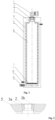
Fig. 1 is a section view of a desulfurization unit. -
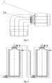
Fig. 2 is a structural schematic view of a double threaded bush. -
Fig. 3 is a structural schematic view of a right-angle adapter. -
Fig. 4 is a schematic view of two cascading desulfurization units. - The following reference numerals are used in the description and drawings: 1-right-angle adapter, 1a-filter element, 2-circumferential locating pin, 3-double threaded bush, 3a-outer bush, 3b-inner bush, 4-water cavity, 5-container, 6-inner cavity, 7-grid plate, 8-circulating water ferrule-type joint, 9-straight adapter.
- An object of the present invention is to provide a desulfurization unit of an SOFC system. The structural design of the desulfurization unit of the SOFC system can help solve the problem of slow temperature rise of the desulfurizing agent in the desulfurization unit of the SOFC system. A further object of the present invention is to provide an SOFC system and a vehicle comprising the foregoing desulfurization unit.
- Embodiments of the present invention will be described below in conjunction with the drawings. The described embodiments are only some, not all of the embodiments of the present invention.
- In the description of the present invention, it should be understood that terms indicating directional or positional relations such as "over," "on," "above," "below," "under," "front," "rear," "left" and "right" are based on the directional or positional relations shown in the drawings. They are only for facilitating and simplifying the description of the present invention, and do not indicate or imply that the devices or elements in question must possess specific directions or be constructed and operated in specific directions, so they cannot be understood as limitations to this solution. Further, the terms "first" and "second" are intended for description only and cannot be understood to indicate or imply relative importance or implicitly indicate the quantity of the demonstrated technical features.
- As shown in
Fig. 1 to Fig. 4 , the desulfurization unit of the SOFC system provided by the present invention comprises acontainer 5 and a double threaded bush 3. An inner cavity 6 of thecontainer 5 is used for holding a desulfurizing agent. Thecontainer 5 comprises an inner wall and an outer wall, a water cavity 4 is formed between the inner wall and the outer wall, and a water inlet and a water outlet in communication with the water cavity 4 are arranged on the outer wall. In other words, circulating water can enter the water cavity 4 from the water inlet, circulate inside the water cavity 4 and then be discharged out of the water cavity 4 from the water outlet. The inner cavity 6 is a cavity on the inner side of the inner wall. The desulfurizing agent is kept in the inner cavity 6. - The top of the
container 5 is provided with a gas outlet, which communicates with the inner cavity 6. The bottom of thecontainer 5 is provided with a gas inlet, which also communicates with the inner cavity 6. Gas enters the inner cavity 6 from the gas inlet, is desulfurized by the desulfurizing agent and then is discharged from the gas outlet. - A double threaded bush 3 is arranged at the gas outlet. The double threaded bush 3 comprises an
inner bush 3b and anouter bush 3a that adopt a nested setting, and threaded connection is adopted between theinner bush 3b and theouter bush 3a, i.e., the outer wall of theinner bush 3b is in screw-thread fit with the inner wall of theouter bush 3a. The outer wall of theouter bush 3a is connected to the hole wall of the gas outlet in a threaded manner, and the inner wall of theinner bush 3b is connected to the adapter in a threaded manner. - When the desulfurization unit of the SOFC system provided by the present invention is used, the water inlet and the water outlet are communicable with the circulating water of the whole vehicle, and the circulating water of the whole vehicle enters the water cavity 4 from the water inlet, is circulated in the water cavity 4 and then is discharged out of the water cavity 4 from the water outlet. Further, the circulating water of the whole vehicle heats the desulfurizing agent in the water cavity 4. In this way, the desulfurizing agent can be heated up once the vehicle is started, and the temperature of the desulfurizing agent can be quickly raised to the operating ambient temperature. This effect is better than a conventional method of heating by gas.
- Further, the connection with a double threaded bush has good sealing performance. When the desulfurizing agent needs to be replaced, the
outer bush 3a andinner bush 3b can be rotated and disassembled together. The diameter of theouter bush 3a is larger to facilitate the rapid outflow or inflow of the desulfurizing agent. To replace the adapter, only rotation of the adapter and theinner bush 3b is needed. This design is not only conducive to frequent adapter replacement without damaging thecontainer 5, but also conducive to adopting a larger diameter to speed up the replacement of the desulfurizing agent. - In order to make the distribution of a turbulent gas more uniform, the bottom of the
container 5 can be further provided with agrid plate 7. A buffer cavity is arranged under thegrid plate 7 and the gas entering from the gas inlet flows through the buffer cavity and thegrid plate 7 in turn. With this setting, thegrid plate 7 can support the desulfurizing agent and moreover, after the turbulent gas under thegrid plate 7 flows through thegrid plate 7, the gas is more uniformly distributed. A plurality of round through holes or through holes in other shapes can be arranged on thegrid plate 7. Thegrid plate 7 can be agrid plate 7 densely perforated by lasers. - In order to prevent the
outer bush 3a from rotating together with theinner bush 3b during disassembly or installation of the adapter, at least onecircumferential locating pin 2 can be arranged between theouter bush 3a and the hole wall of the gas outlet. Thecircumferential locating pin 2 can prevent rotation of theouter bush 3a. To replace the desulfurizing agent, only removal of thecircumferential locating pin 2 and rotation of theouter bush 3a are needed. - The
circumferential locating pin 2 can pass through a pin hole on theouter bush 3a and be inserted into the pin hole on the hole wall of the gas outlet. - The
container 5 can be rectangular. The desulfurization units can be used alone, and a single unit has a small volume and a small weight and facilitates the installation and replacement of the desulfurizing agent. Alternatively, a plurality of desulfurization units can be used in a combined manner, and according to different catalysts and use requirements, a different number of desulfurization units are connected in series and quickly assembled to increase the volume of the desulfurizing agent and achieve the desulfurization effect. Further, the desulfurization unit can also be fixed on the side wall of the vehicle environment compartment conveniently. Compared with a cylindrical desulfurization tank, the desulfurization unit can effectively utilize the space and save installation space for other systems. - In one embodiment, the water inlet and the water outlet are located in the upper part and the lower part of the
container 5 respectively, so as to make the best use of the heat of the circulating water. Further, the water inlet and the water outlet can be arranged on two sides of thecontainer 5. The water inlet is in the lower part of thecontainer 5 and the water outlet is in the upper part of thecontainer 5. - The water inlet and the water outlet may further be provided with a circulating water ferrule-type joint 8 to facilitate connection to other components. There is no limitation to it.
- Further, the foregoing adapter connected to the
inner bush 3b can be a right-angle adapter 1, to further facilitate connection to other components. Further, in order to prevent particles of the desulfurizing agent from overflowing together with the gas, a filter element 1a is integrated on the right-angle connector. The filter element 1a is a sinter-type filter element to trap particles of size 0.5 µm and above. - An adapter is further arranged at the gas inlet. The adapter at the gas inlet can be a
straight adapter 9. A filter element 1a can be integrated on the adapter at the gas inlet, too. The adapter at the gas inlet and the adapter connected to theinner bush 3b both can be ferrule-type adapters. - Based on the desulfurization unit provided by the foregoing embodiment, the present invention further provides an SOFC system. The SOFC system comprises any desulfurization unit provided by the foregoing embodiments. As the SOFC system adopts the desulfurization unit provided by the foregoing embodiments, the beneficial effects of the SOFC system can be seen in the foregoing embodiments.
- Further, the SOFC system comprises a plurality of desulfurization units, and any two of the desulfurization units are connected in series or in parallel. A plurality of desulfurization units can be connected in series or in parallel.
- The present invention further provides a vehicle. The vehicle comprises the foregoing SOFC system, so the beneficial effects of the vehicle can be seen in the foregoing embodiments.
- The embodiments in the description are all described in a progressive manner, each embodiment focuses on the differences from other embodiments and the same or similar parts among the embodiments can be mutually referred to.
- Various modifications to these embodiments will be apparent. The general principle defined herein can be implemented in other embodiments without departing from the scope of the present invention. Therefore, the present invention will not be limited to the embodiments provided herein.
- The description with reference to the terms "one embodiment," "example," "specific example," etc. means that the specific features, structures, materials, or characteristics described in combination with the embodiment or example are included in at least one embodiment or example of the invention. The schematic representation of the above-mentioned terms herein does not necessarily refer to the same embodiment or example. Moreover, the specific features, structures, materials, or characteristics described can be combined in any one or multiple embodiments or examples in a suitable manner.
Claims (10)
- A desulfurization unit of a solid oxide fuel cell (SOFC) system, comprising a container for holding a desulfurizing agent (5), wherein:the container (5) comprises an inner wall and an outer wall, a water cavity (4) is formed between the inner wall and the outer wall;a water inlet and a water outlet in communication with the water cavity (4) are arranged on the outer wall;the top of the container (5) is provided with a gas outlet;the bottom of the container (5) is provided with a gas inlet; anda double threaded bush (3) is arranged at the gas outlet, wherein:the double threaded bush (3) comprises an inner bush (3b) and an outer bush (3a) in a threaded engagement;an outer wall of the outer bush (3a) is in threaded engagement with a wall of the gas outlet; andan inner wall of the inner bush (3b) is in threaded engagement with an adapter.
- The desulfurization unit of the SOFC system according to claim 1, wherein the bottom of the container (5) is provided with a grid plate (7), a buffer cavity is arranged under the grid plate (7) such that the gas entering from the gas inlet will flow through the buffer cavity and the grid plate (7) in turn.
- The desulfurization unit of the SOFC system according to claim 1 or 2, wherein at least one circumferential locating pin (2) is further provided between the outer bush (3a) and the wall of the gas outlet.
- The desulfurization unit of the SOFC system according to claim 1, 2, or 3, wherein the container (5) is rectangular.
- The desulfurization unit of the SOFC system according to claim 4, wherein the water inlet and the water outlet are located in the upper part and the lower part of the container (5) respectively.
- The desulfurization unit of the SOFC system according to any preceding claim, wherein the adapter is a right-angle adapter (1).
- The desulfurization unit of the SOFC system according to claim 6, wherein a filter element (1a) is further integrated on the right-angle connector.
- An SOFC system comprising at least one desulfurization unit according to any one of claims 1 to 7.
- The SOFC system according to claim 8, wherein there are a plurality of desulfurization units, and any two of the desulfurization units are connected in series or parallel.
- A vehicle, wherein the vehicle comprises the SOFC system according to any one of claims 8 to 9.
Applications Claiming Priority (2)
| Application Number | Priority Date | Filing Date | Title |
|---|---|---|---|
| CN201921999676.0U CN211302622U (en) | 2019-11-19 | 2019-11-19 | Desulfurization device, SOFC system and vehicle |
| PCT/IB2020/060861 WO2021099958A1 (en) | 2019-11-19 | 2020-11-18 | Desulfurization unit, sofc system and vehicle |
Publications (2)
| Publication Number | Publication Date |
|---|---|
| EP4061508A1 EP4061508A1 (en) | 2022-09-28 |
| EP4061508B1 true EP4061508B1 (en) | 2023-12-13 |
Family
ID=72078677
Family Applications (1)
| Application Number | Title | Priority Date | Filing Date |
|---|---|---|---|
| EP20828304.4A Active EP4061508B1 (en) | 2019-11-19 | 2020-11-18 | Desulfurization unit, sofc system and vehicle |
Country Status (9)
| Country | Link |
|---|---|
| US (1) | US20220407099A1 (en) |
| EP (1) | EP4061508B1 (en) |
| JP (1) | JP2023501598A (en) |
| KR (1) | KR20220098153A (en) |
| CN (1) | CN211302622U (en) |
| AU (1) | AU2020385696A1 (en) |
| CA (1) | CA3161468A1 (en) |
| GB (1) | GB2604803B (en) |
| WO (1) | WO2021099958A1 (en) |
Families Citing this family (1)
| Publication number | Priority date | Publication date | Assignee | Title |
|---|---|---|---|---|
| CN117861408B (en) * | 2024-02-26 | 2024-12-20 | 潮州三环(集团)股份有限公司 | A desulfurization device |
Family Cites Families (17)
| Publication number | Priority date | Publication date | Assignee | Title |
|---|---|---|---|---|
| US4940529A (en) * | 1989-07-18 | 1990-07-10 | Amoco Corporation | Catalytic cracking with deasphalted oil |
| US5013427A (en) * | 1989-07-18 | 1991-05-07 | Amoco Corportion | Resid hydrotreating with resins |
| KR100209989B1 (en) * | 1996-12-23 | 1999-07-15 | 남창우 | Natural Gas Hydrogen Generator |
| EP1849515A3 (en) * | 2001-10-17 | 2007-12-05 | Mitsubishi Heavy Industries, Ltd. | Flue gas desulfurization apparatus, flue gas desulfurization system, and method for operating flue gas desulfurization apparatus |
| JP4302372B2 (en) * | 2002-07-23 | 2009-07-22 | 出光興産株式会社 | Desulfurizer and desulfurization method |
| JP4215539B2 (en) * | 2003-03-04 | 2009-01-28 | 出光興産株式会社 | Desulfurizer and desulfurization method |
| JP5148164B2 (en) * | 2007-05-15 | 2013-02-20 | 東芝燃料電池システム株式会社 | Liquid fuel processing apparatus and fuel cell power generation system |
| JP5265277B2 (en) * | 2008-09-08 | 2013-08-14 | 本田技研工業株式会社 | Desulfurization equipment |
| JP5738318B2 (en) * | 2010-12-27 | 2015-06-24 | Jx日鉱日石エネルギー株式会社 | Desulfurization apparatus and fuel cell system |
| JP5657403B2 (en) * | 2011-01-17 | 2015-01-21 | Jx日鉱日石エネルギー株式会社 | Desulfurizer |
| JP5799085B2 (en) * | 2011-03-25 | 2015-10-21 | Jx日鉱日石エネルギー株式会社 | Desulfurizer |
| US20150275108A1 (en) * | 2012-10-25 | 2015-10-01 | How Kiap Gueh | Gasification devices and methods |
| CN105228728A (en) * | 2013-09-17 | 2016-01-06 | 株式会社Ihi | The treatment system of waste gas and processing method |
| JP6190764B2 (en) * | 2014-06-06 | 2017-08-30 | 本田技研工業株式会社 | Desulfurizer |
| CN204638201U (en) * | 2015-05-19 | 2015-09-16 | 江苏创新石化有限公司 | A kind of desulfurizing agent vacuum condensation liquid processing device |
| CN207672008U (en) * | 2017-11-27 | 2018-07-31 | 上海中弗新能源科技有限公司 | A kind of SOFC electricity generation systems natural-gas desulfurizer |
| KR20240137558A (en) * | 2022-01-24 | 2024-09-20 | 토프쉐 에이/에스 | Conversion of CO2 and H2 into synthesis gas |
-
2019
- 2019-11-19 CN CN201921999676.0U patent/CN211302622U/en active Active
-
2020
- 2020-11-18 JP JP2022527756A patent/JP2023501598A/en not_active Withdrawn
- 2020-11-18 US US17/777,513 patent/US20220407099A1/en not_active Abandoned
- 2020-11-18 GB GB2207178.1A patent/GB2604803B/en not_active Expired - Fee Related
- 2020-11-18 AU AU2020385696A patent/AU2020385696A1/en not_active Abandoned
- 2020-11-18 EP EP20828304.4A patent/EP4061508B1/en active Active
- 2020-11-18 KR KR1020227017445A patent/KR20220098153A/en not_active Withdrawn
- 2020-11-18 WO PCT/IB2020/060861 patent/WO2021099958A1/en not_active Ceased
- 2020-11-18 CA CA3161468A patent/CA3161468A1/en active Pending
Also Published As
| Publication number | Publication date |
|---|---|
| AU2020385696A1 (en) | 2022-06-09 |
| JP2023501598A (en) | 2023-01-18 |
| GB2604803A (en) | 2022-09-14 |
| CN211302622U (en) | 2020-08-21 |
| KR20220098153A (en) | 2022-07-11 |
| EP4061508A1 (en) | 2022-09-28 |
| US20220407099A1 (en) | 2022-12-22 |
| WO2021099958A1 (en) | 2021-05-27 |
| GB202207178D0 (en) | 2022-06-29 |
| CA3161468A1 (en) | 2021-05-27 |
| GB2604803B (en) | 2024-02-28 |
Similar Documents
| Publication | Publication Date | Title |
|---|---|---|
| EP2767514B1 (en) | Ion exchanger and cooling device equipped with ion exchanger | |
| EP4061508B1 (en) | Desulfurization unit, sofc system and vehicle | |
| CN108183280B (en) | Electric automobile power battery cooling device and cooling system thereof | |
| KR101362055B1 (en) | Cooling device for fuel cell | |
| CN210805963U (en) | Cooling plate, battery pack, and electric vehicle | |
| CN206516689U (en) | Support meanss, battery modules and power-supply system | |
| CN210723286U (en) | High-power lithium battery pack structure in environment below 40 DEG | |
| CN212109705U (en) | Heat exchange plate, printed circuit board type heat exchanger and hydrogenation machine | |
| CN209329007U (en) | Cell installation structure, energy storage module and vehicle | |
| CN220635652U (en) | Multi-head negative pressure cleaning equipment for transverse placement of polar posts on two sides of square lithium battery | |
| CN206370478U (en) | A kind of electrokinetic cell cooling and heating integrated system and battery | |
| CN217086689U (en) | Heat dissipation cold plate of energy storage battery pack | |
| CN212619354U (en) | Constant temperature storehouse and water heater | |
| CN222838909U (en) | Energy storage system liquid cooling pipeline with balanced heat dissipation | |
| CN209658643U (en) | A kind of power distribution cabinet with cooling device | |
| CN106684490A (en) | Water-cooling heat dissipation apparatus for battery pack of new energy automobile | |
| CN207963126U (en) | Heat accumulating type wind tunnel experiment electricity heating device system | |
| CN220774508U (en) | Cooling device and power battery | |
| CN219616241U (en) | Cleaning tool for bipolar plate | |
| CN222654074U (en) | Cooling device for battery cluster or battery cabinet | |
| CN216745577U (en) | Forced freezing heat exchanger | |
| CN218994116U (en) | Shell-and-tube heat exchanger | |
| CN222839438U (en) | Cold plate type liquid cooling charging module | |
| CN222581247U (en) | Battery pack and energy storage system | |
| CN223297893U (en) | Electrolyte pretreatment system and electrolyte pretreatment cabinet |
Legal Events
| Date | Code | Title | Description |
|---|---|---|---|
| STAA | Information on the status of an ep patent application or granted ep patent |
Free format text: STATUS: UNKNOWN |
|
| STAA | Information on the status of an ep patent application or granted ep patent |
Free format text: STATUS: THE INTERNATIONAL PUBLICATION HAS BEEN MADE |
|
| PUAI | Public reference made under article 153(3) epc to a published international application that has entered the european phase |
Free format text: ORIGINAL CODE: 0009012 |
|
| STAA | Information on the status of an ep patent application or granted ep patent |
Free format text: STATUS: REQUEST FOR EXAMINATION WAS MADE |
|
| 17P | Request for examination filed |
Effective date: 20220517 |
|
| AK | Designated contracting states |
Kind code of ref document: A1 Designated state(s): AL AT BE BG CH CY CZ DE DK EE ES FI FR GB GR HR HU IE IS IT LI LT LU LV MC MK MT NL NO PL PT RO RS SE SI SK SM TR |
|
| DAV | Request for validation of the european patent (deleted) | ||
| DAX | Request for extension of the european patent (deleted) | ||
| P01 | Opt-out of the competence of the unified patent court (upc) registered |
Effective date: 20230525 |
|
| GRAP | Despatch of communication of intention to grant a patent |
Free format text: ORIGINAL CODE: EPIDOSNIGR1 |
|
| STAA | Information on the status of an ep patent application or granted ep patent |
Free format text: STATUS: GRANT OF PATENT IS INTENDED |
|
| INTG | Intention to grant announced |
Effective date: 20230718 |
|
| GRAS | Grant fee paid |
Free format text: ORIGINAL CODE: EPIDOSNIGR3 |
|
| GRAA | (expected) grant |
Free format text: ORIGINAL CODE: 0009210 |
|
| STAA | Information on the status of an ep patent application or granted ep patent |
Free format text: STATUS: THE PATENT HAS BEEN GRANTED |
|
| AK | Designated contracting states |
Kind code of ref document: B1 Designated state(s): AL AT BE BG CH CY CZ DE DK EE ES FI FR GB GR HR HU IE IS IT LI LT LU LV MC MK MT NL NO PL PT RO RS SE SI SK SM TR |
|
| REG | Reference to a national code |
Ref country code: GB Ref legal event code: FG4D |
|
| REG | Reference to a national code |
Ref country code: CH Ref legal event code: EP |
|
| REG | Reference to a national code |
Ref country code: DE Ref legal event code: R096 Ref document number: 602020022840 Country of ref document: DE |
|
| REG | Reference to a national code |
Ref country code: IE Ref legal event code: FG4D |
|
| PG25 | Lapsed in a contracting state [announced via postgrant information from national office to epo] |
Ref country code: GR Free format text: LAPSE BECAUSE OF FAILURE TO SUBMIT A TRANSLATION OF THE DESCRIPTION OR TO PAY THE FEE WITHIN THE PRESCRIBED TIME-LIMIT Effective date: 20240314 |
|
| REG | Reference to a national code |
Ref country code: LT Ref legal event code: MG9D |
|
| PG25 | Lapsed in a contracting state [announced via postgrant information from national office to epo] |
Ref country code: LT Free format text: LAPSE BECAUSE OF FAILURE TO SUBMIT A TRANSLATION OF THE DESCRIPTION OR TO PAY THE FEE WITHIN THE PRESCRIBED TIME-LIMIT Effective date: 20231213 |
|
| REG | Reference to a national code |
Ref country code: NL Ref legal event code: MP Effective date: 20231213 |
|
| PG25 | Lapsed in a contracting state [announced via postgrant information from national office to epo] |
Ref country code: ES Free format text: LAPSE BECAUSE OF FAILURE TO SUBMIT A TRANSLATION OF THE DESCRIPTION OR TO PAY THE FEE WITHIN THE PRESCRIBED TIME-LIMIT Effective date: 20231213 |
|
| PG25 | Lapsed in a contracting state [announced via postgrant information from national office to epo] |
Ref country code: LT Free format text: LAPSE BECAUSE OF FAILURE TO SUBMIT A TRANSLATION OF THE DESCRIPTION OR TO PAY THE FEE WITHIN THE PRESCRIBED TIME-LIMIT Effective date: 20231213 Ref country code: GR Free format text: LAPSE BECAUSE OF FAILURE TO SUBMIT A TRANSLATION OF THE DESCRIPTION OR TO PAY THE FEE WITHIN THE PRESCRIBED TIME-LIMIT Effective date: 20240314 Ref country code: ES Free format text: LAPSE BECAUSE OF FAILURE TO SUBMIT A TRANSLATION OF THE DESCRIPTION OR TO PAY THE FEE WITHIN THE PRESCRIBED TIME-LIMIT Effective date: 20231213 Ref country code: BG Free format text: LAPSE BECAUSE OF FAILURE TO SUBMIT A TRANSLATION OF THE DESCRIPTION OR TO PAY THE FEE WITHIN THE PRESCRIBED TIME-LIMIT Effective date: 20240313 |
|
| REG | Reference to a national code |
Ref country code: AT Ref legal event code: MK05 Ref document number: 1640012 Country of ref document: AT Kind code of ref document: T Effective date: 20231213 |
|
| PG25 | Lapsed in a contracting state [announced via postgrant information from national office to epo] |
Ref country code: NL Free format text: LAPSE BECAUSE OF FAILURE TO SUBMIT A TRANSLATION OF THE DESCRIPTION OR TO PAY THE FEE WITHIN THE PRESCRIBED TIME-LIMIT Effective date: 20231213 |
|
| PG25 | Lapsed in a contracting state [announced via postgrant information from national office to epo] |
Ref country code: SE Free format text: LAPSE BECAUSE OF FAILURE TO SUBMIT A TRANSLATION OF THE DESCRIPTION OR TO PAY THE FEE WITHIN THE PRESCRIBED TIME-LIMIT Effective date: 20231213 Ref country code: RS Free format text: LAPSE BECAUSE OF FAILURE TO SUBMIT A TRANSLATION OF THE DESCRIPTION OR TO PAY THE FEE WITHIN THE PRESCRIBED TIME-LIMIT Effective date: 20231213 Ref country code: NO Free format text: LAPSE BECAUSE OF FAILURE TO SUBMIT A TRANSLATION OF THE DESCRIPTION OR TO PAY THE FEE WITHIN THE PRESCRIBED TIME-LIMIT Effective date: 20240313 Ref country code: NL Free format text: LAPSE BECAUSE OF FAILURE TO SUBMIT A TRANSLATION OF THE DESCRIPTION OR TO PAY THE FEE WITHIN THE PRESCRIBED TIME-LIMIT Effective date: 20231213 Ref country code: LV Free format text: LAPSE BECAUSE OF FAILURE TO SUBMIT A TRANSLATION OF THE DESCRIPTION OR TO PAY THE FEE WITHIN THE PRESCRIBED TIME-LIMIT Effective date: 20231213 Ref country code: HR Free format text: LAPSE BECAUSE OF FAILURE TO SUBMIT A TRANSLATION OF THE DESCRIPTION OR TO PAY THE FEE WITHIN THE PRESCRIBED TIME-LIMIT Effective date: 20231213 |
|
| PG25 | Lapsed in a contracting state [announced via postgrant information from national office to epo] |
Ref country code: IS Free format text: LAPSE BECAUSE OF FAILURE TO SUBMIT A TRANSLATION OF THE DESCRIPTION OR TO PAY THE FEE WITHIN THE PRESCRIBED TIME-LIMIT Effective date: 20240413 |
|
| PG25 | Lapsed in a contracting state [announced via postgrant information from national office to epo] |
Ref country code: AT Free format text: LAPSE BECAUSE OF FAILURE TO SUBMIT A TRANSLATION OF THE DESCRIPTION OR TO PAY THE FEE WITHIN THE PRESCRIBED TIME-LIMIT Effective date: 20231213 Ref country code: CZ Free format text: LAPSE BECAUSE OF FAILURE TO SUBMIT A TRANSLATION OF THE DESCRIPTION OR TO PAY THE FEE WITHIN THE PRESCRIBED TIME-LIMIT Effective date: 20231213 |
|
| PG25 | Lapsed in a contracting state [announced via postgrant information from national office to epo] |
Ref country code: SK Free format text: LAPSE BECAUSE OF FAILURE TO SUBMIT A TRANSLATION OF THE DESCRIPTION OR TO PAY THE FEE WITHIN THE PRESCRIBED TIME-LIMIT Effective date: 20231213 |
|
| PG25 | Lapsed in a contracting state [announced via postgrant information from national office to epo] |
Ref country code: SM Free format text: LAPSE BECAUSE OF FAILURE TO SUBMIT A TRANSLATION OF THE DESCRIPTION OR TO PAY THE FEE WITHIN THE PRESCRIBED TIME-LIMIT Effective date: 20231213 Ref country code: SK Free format text: LAPSE BECAUSE OF FAILURE TO SUBMIT A TRANSLATION OF THE DESCRIPTION OR TO PAY THE FEE WITHIN THE PRESCRIBED TIME-LIMIT Effective date: 20231213 Ref country code: RO Free format text: LAPSE BECAUSE OF FAILURE TO SUBMIT A TRANSLATION OF THE DESCRIPTION OR TO PAY THE FEE WITHIN THE PRESCRIBED TIME-LIMIT Effective date: 20231213 Ref country code: IT Free format text: LAPSE BECAUSE OF FAILURE TO SUBMIT A TRANSLATION OF THE DESCRIPTION OR TO PAY THE FEE WITHIN THE PRESCRIBED TIME-LIMIT Effective date: 20231213 Ref country code: IS Free format text: LAPSE BECAUSE OF FAILURE TO SUBMIT A TRANSLATION OF THE DESCRIPTION OR TO PAY THE FEE WITHIN THE PRESCRIBED TIME-LIMIT Effective date: 20240413 Ref country code: EE Free format text: LAPSE BECAUSE OF FAILURE TO SUBMIT A TRANSLATION OF THE DESCRIPTION OR TO PAY THE FEE WITHIN THE PRESCRIBED TIME-LIMIT Effective date: 20231213 Ref country code: CZ Free format text: LAPSE BECAUSE OF FAILURE TO SUBMIT A TRANSLATION OF THE DESCRIPTION OR TO PAY THE FEE WITHIN THE PRESCRIBED TIME-LIMIT Effective date: 20231213 Ref country code: AT Free format text: LAPSE BECAUSE OF FAILURE TO SUBMIT A TRANSLATION OF THE DESCRIPTION OR TO PAY THE FEE WITHIN THE PRESCRIBED TIME-LIMIT Effective date: 20231213 |
|
| PG25 | Lapsed in a contracting state [announced via postgrant information from national office to epo] |
Ref country code: PL Free format text: LAPSE BECAUSE OF FAILURE TO SUBMIT A TRANSLATION OF THE DESCRIPTION OR TO PAY THE FEE WITHIN THE PRESCRIBED TIME-LIMIT Effective date: 20231213 Ref country code: PT Free format text: LAPSE BECAUSE OF FAILURE TO SUBMIT A TRANSLATION OF THE DESCRIPTION OR TO PAY THE FEE WITHIN THE PRESCRIBED TIME-LIMIT Effective date: 20240415 |
|
| PG25 | Lapsed in a contracting state [announced via postgrant information from national office to epo] |
Ref country code: PT Free format text: LAPSE BECAUSE OF FAILURE TO SUBMIT A TRANSLATION OF THE DESCRIPTION OR TO PAY THE FEE WITHIN THE PRESCRIBED TIME-LIMIT Effective date: 20240415 Ref country code: PL Free format text: LAPSE BECAUSE OF FAILURE TO SUBMIT A TRANSLATION OF THE DESCRIPTION OR TO PAY THE FEE WITHIN THE PRESCRIBED TIME-LIMIT Effective date: 20231213 |
|
| REG | Reference to a national code |
Ref country code: DE Ref legal event code: R097 Ref document number: 602020022840 Country of ref document: DE |
|
| PG25 | Lapsed in a contracting state [announced via postgrant information from national office to epo] |
Ref country code: DK Free format text: LAPSE BECAUSE OF FAILURE TO SUBMIT A TRANSLATION OF THE DESCRIPTION OR TO PAY THE FEE WITHIN THE PRESCRIBED TIME-LIMIT Effective date: 20231213 |
|
| PLBE | No opposition filed within time limit |
Free format text: ORIGINAL CODE: 0009261 |
|
| STAA | Information on the status of an ep patent application or granted ep patent |
Free format text: STATUS: NO OPPOSITION FILED WITHIN TIME LIMIT |
|
| PG25 | Lapsed in a contracting state [announced via postgrant information from national office to epo] |
Ref country code: SI Free format text: LAPSE BECAUSE OF FAILURE TO SUBMIT A TRANSLATION OF THE DESCRIPTION OR TO PAY THE FEE WITHIN THE PRESCRIBED TIME-LIMIT Effective date: 20231213 |
|
| PG25 | Lapsed in a contracting state [announced via postgrant information from national office to epo] |
Ref country code: SI Free format text: LAPSE BECAUSE OF FAILURE TO SUBMIT A TRANSLATION OF THE DESCRIPTION OR TO PAY THE FEE WITHIN THE PRESCRIBED TIME-LIMIT Effective date: 20231213 Ref country code: DK Free format text: LAPSE BECAUSE OF FAILURE TO SUBMIT A TRANSLATION OF THE DESCRIPTION OR TO PAY THE FEE WITHIN THE PRESCRIBED TIME-LIMIT Effective date: 20231213 |
|
| 26N | No opposition filed |
Effective date: 20240916 |
|
| REG | Reference to a national code |
Ref country code: DE Ref legal event code: R119 Ref document number: 602020022840 Country of ref document: DE |
|
| REG | Reference to a national code |
Ref country code: CH Ref legal event code: PL |
|
| PG25 | Lapsed in a contracting state [announced via postgrant information from national office to epo] |
Ref country code: MC Free format text: LAPSE BECAUSE OF FAILURE TO SUBMIT A TRANSLATION OF THE DESCRIPTION OR TO PAY THE FEE WITHIN THE PRESCRIBED TIME-LIMIT Effective date: 20231213 |
|
| PG25 | Lapsed in a contracting state [announced via postgrant information from national office to epo] |
Ref country code: LU Free format text: LAPSE BECAUSE OF NON-PAYMENT OF DUE FEES Effective date: 20241118 |
|
| REG | Reference to a national code |
Ref country code: CH Ref legal event code: PL |
|
| GBPC | Gb: european patent ceased through non-payment of renewal fee |
Effective date: 20241118 |
|
| PG25 | Lapsed in a contracting state [announced via postgrant information from national office to epo] |
Ref country code: CH Free format text: LAPSE BECAUSE OF NON-PAYMENT OF DUE FEES Effective date: 20241130 |
|
| REG | Reference to a national code |
Ref country code: BE Ref legal event code: MM Effective date: 20241130 |
|
| PG25 | Lapsed in a contracting state [announced via postgrant information from national office to epo] |
Ref country code: FI Free format text: LAPSE BECAUSE OF FAILURE TO SUBMIT A TRANSLATION OF THE DESCRIPTION OR TO PAY THE FEE WITHIN THE PRESCRIBED TIME-LIMIT Effective date: 20231213 |
|
| PG25 | Lapsed in a contracting state [announced via postgrant information from national office to epo] |
Ref country code: DE Free format text: LAPSE BECAUSE OF NON-PAYMENT OF DUE FEES Effective date: 20250603 |
|
| PG25 | Lapsed in a contracting state [announced via postgrant information from national office to epo] |
Ref country code: GB Free format text: LAPSE BECAUSE OF NON-PAYMENT OF DUE FEES Effective date: 20241118 Ref country code: BE Free format text: LAPSE BECAUSE OF NON-PAYMENT OF DUE FEES Effective date: 20241130 |
|
| PG25 | Lapsed in a contracting state [announced via postgrant information from national office to epo] |
Ref country code: FR Free format text: LAPSE BECAUSE OF NON-PAYMENT OF DUE FEES Effective date: 20241130 |
|
| PG25 | Lapsed in a contracting state [announced via postgrant information from national office to epo] |
Ref country code: IE Free format text: LAPSE BECAUSE OF NON-PAYMENT OF DUE FEES Effective date: 20241118 |
|
| PG25 | Lapsed in a contracting state [announced via postgrant information from national office to epo] |
Ref country code: HU Free format text: LAPSE BECAUSE OF FAILURE TO SUBMIT A TRANSLATION OF THE DESCRIPTION OR TO PAY THE FEE WITHIN THE PRESCRIBED TIME-LIMIT; INVALID AB INITIO Effective date: 20201118 |
|
| PG25 | Lapsed in a contracting state [announced via postgrant information from national office to epo] |
Ref country code: CY Free format text: LAPSE BECAUSE OF FAILURE TO SUBMIT A TRANSLATION OF THE DESCRIPTION OR TO PAY THE FEE WITHIN THE PRESCRIBED TIME-LIMIT; INVALID AB INITIO Effective date: 20201118 |