EP4060968A1 - Mobiles endgerät und steuerungsverfahren dafür - Google Patents
Mobiles endgerät und steuerungsverfahren dafür Download PDFInfo
- Publication number
- EP4060968A1 EP4060968A1 EP19952939.7A EP19952939A EP4060968A1 EP 4060968 A1 EP4060968 A1 EP 4060968A1 EP 19952939 A EP19952939 A EP 19952939A EP 4060968 A1 EP4060968 A1 EP 4060968A1
- Authority
- EP
- European Patent Office
- Prior art keywords
- mobile terminal
- display
- frame
- knock code
- region
- Prior art date
- Legal status (The legal status is an assumption and is not a legal conclusion. Google has not performed a legal analysis and makes no representation as to the accuracy of the status listed.)
- Granted
Links
Images


Classifications
-
- H—ELECTRICITY
- H04—ELECTRIC COMMUNICATION TECHNIQUE
- H04M—TELEPHONIC COMMUNICATION
- H04M1/00—Substation equipment, e.g. for use by subscribers
- H04M1/02—Constructional features of telephone sets
- H04M1/0202—Portable telephone sets, e.g. cordless phones, mobile phones or bar type handsets
- H04M1/0206—Portable telephones comprising a plurality of mechanically joined movable body parts, e.g. hinged housings
- H04M1/0208—Portable telephones comprising a plurality of mechanically joined movable body parts, e.g. hinged housings characterized by the relative motions of the body parts
- H04M1/0235—Slidable or telescopic telephones, i.e. with a relative translation movement of the body parts; Telephones using a combination of translation and other relative motions of the body parts
- H04M1/0237—Sliding mechanism with one degree of freedom
-
- H—ELECTRICITY
- H04—ELECTRIC COMMUNICATION TECHNIQUE
- H04M—TELEPHONIC COMMUNICATION
- H04M1/00—Substation equipment, e.g. for use by subscribers
- H04M1/72—Mobile telephones; Cordless telephones, i.e. devices for establishing wireless links to base stations without route selection
- H04M1/724—User interfaces specially adapted for cordless or mobile telephones
- H04M1/72448—User interfaces specially adapted for cordless or mobile telephones with means for adapting the functionality of the device according to specific conditions
- H04M1/72463—User interfaces specially adapted for cordless or mobile telephones with means for adapting the functionality of the device according to specific conditions to restrict the functionality of the device
- H04M1/724631—User interfaces specially adapted for cordless or mobile telephones with means for adapting the functionality of the device according to specific conditions to restrict the functionality of the device by limiting the access to the user interface, e.g. locking a touch-screen or a keypad
-
- H—ELECTRICITY
- H04—ELECTRIC COMMUNICATION TECHNIQUE
- H04M—TELEPHONIC COMMUNICATION
- H04M1/00—Substation equipment, e.g. for use by subscribers
- H04M1/02—Constructional features of telephone sets
- H04M1/0202—Portable telephone sets, e.g. cordless phones, mobile phones or bar type handsets
- H04M1/026—Details of the structure or mounting of specific components
- H04M1/0266—Details of the structure or mounting of specific components for a display module assembly
- H04M1/0268—Details of the structure or mounting of specific components for a display module assembly including a flexible display panel
-
- G—PHYSICS
- G06—COMPUTING OR CALCULATING; COUNTING
- G06F—ELECTRIC DIGITAL DATA PROCESSING
- G06F1/00—Details not covered by groups G06F3/00 - G06F13/00 and G06F21/00
- G06F1/16—Constructional details or arrangements
- G06F1/1613—Constructional details or arrangements for portable computers
- G06F1/1615—Constructional details or arrangements for portable computers with several enclosures having relative motions, each enclosure supporting at least one I/O or computing function
- G06F1/1624—Constructional details or arrangements for portable computers with several enclosures having relative motions, each enclosure supporting at least one I/O or computing function with sliding enclosures, e.g. sliding keyboard or display
-
- G—PHYSICS
- G06—COMPUTING OR CALCULATING; COUNTING
- G06F—ELECTRIC DIGITAL DATA PROCESSING
- G06F1/00—Details not covered by groups G06F3/00 - G06F13/00 and G06F21/00
- G06F1/16—Constructional details or arrangements
- G06F1/1613—Constructional details or arrangements for portable computers
- G06F1/1633—Constructional details or arrangements of portable computers not specific to the type of enclosures covered by groups G06F1/1615 - G06F1/1626
- G06F1/1637—Details related to the display arrangement, including those related to the mounting of the display in the housing
- G06F1/1652—Details related to the display arrangement, including those related to the mounting of the display in the housing the display being flexible, e.g. mimicking a sheet of paper, or rollable
-
- G—PHYSICS
- G06—COMPUTING OR CALCULATING; COUNTING
- G06F—ELECTRIC DIGITAL DATA PROCESSING
- G06F3/00—Input arrangements for transferring data to be processed into a form capable of being handled by the computer; Output arrangements for transferring data from processing unit to output unit, e.g. interface arrangements
- G06F3/01—Input arrangements or combined input and output arrangements for interaction between user and computer
- G06F3/03—Arrangements for converting the position or the displacement of a member into a coded form
- G06F3/041—Digitisers, e.g. for touch screens or touch pads, characterised by the transducing means
- G06F3/0412—Digitisers structurally integrated in a display
-
- G—PHYSICS
- G06—COMPUTING OR CALCULATING; COUNTING
- G06F—ELECTRIC DIGITAL DATA PROCESSING
- G06F3/00—Input arrangements for transferring data to be processed into a form capable of being handled by the computer; Output arrangements for transferring data from processing unit to output unit, e.g. interface arrangements
- G06F3/01—Input arrangements or combined input and output arrangements for interaction between user and computer
- G06F3/048—Interaction techniques based on graphical user interfaces [GUI]
- G06F3/0484—Interaction techniques based on graphical user interfaces [GUI] for the control of specific functions or operations, e.g. selecting or manipulating an object, an image or a displayed text element, setting a parameter value or selecting a range
-
- G—PHYSICS
- G06—COMPUTING OR CALCULATING; COUNTING
- G06F—ELECTRIC DIGITAL DATA PROCESSING
- G06F3/00—Input arrangements for transferring data to be processed into a form capable of being handled by the computer; Output arrangements for transferring data from processing unit to output unit, e.g. interface arrangements
- G06F3/01—Input arrangements or combined input and output arrangements for interaction between user and computer
- G06F3/048—Interaction techniques based on graphical user interfaces [GUI]
- G06F3/0487—Interaction techniques based on graphical user interfaces [GUI] using specific features provided by the input device, e.g. functions controlled by the rotation of a mouse with dual sensing arrangements, or of the nature of the input device, e.g. tap gestures based on pressure sensed by a digitiser
- G06F3/0488—Interaction techniques based on graphical user interfaces [GUI] using specific features provided by the input device, e.g. functions controlled by the rotation of a mouse with dual sensing arrangements, or of the nature of the input device, e.g. tap gestures based on pressure sensed by a digitiser using a touch-screen or digitiser, e.g. input of commands through traced gestures
- G06F3/04883—Interaction techniques based on graphical user interfaces [GUI] using specific features provided by the input device, e.g. functions controlled by the rotation of a mouse with dual sensing arrangements, or of the nature of the input device, e.g. tap gestures based on pressure sensed by a digitiser using a touch-screen or digitiser, e.g. input of commands through traced gestures for inputting data by handwriting, e.g. gesture or text
-
- G—PHYSICS
- G06—COMPUTING OR CALCULATING; COUNTING
- G06V—IMAGE OR VIDEO RECOGNITION OR UNDERSTANDING
- G06V40/00—Recognition of biometric, human-related or animal-related patterns in image or video data
- G06V40/10—Human or animal bodies, e.g. vehicle occupants or pedestrians; Body parts, e.g. hands
- G06V40/12—Fingerprints or palmprints
-
- H—ELECTRICITY
- H04—ELECTRIC COMMUNICATION TECHNIQUE
- H04M—TELEPHONIC COMMUNICATION
- H04M1/00—Substation equipment, e.g. for use by subscribers
- H04M1/02—Constructional features of telephone sets
- H04M1/0202—Portable telephone sets, e.g. cordless phones, mobile phones or bar type handsets
- H04M1/0206—Portable telephones comprising a plurality of mechanically joined movable body parts, e.g. hinged housings
- H04M1/0208—Portable telephones comprising a plurality of mechanically joined movable body parts, e.g. hinged housings characterized by the relative motions of the body parts
- H04M1/0235—Slidable or telescopic telephones, i.e. with a relative translation movement of the body parts; Telephones using a combination of translation and other relative motions of the body parts
-
- G—PHYSICS
- G06—COMPUTING OR CALCULATING; COUNTING
- G06F—ELECTRIC DIGITAL DATA PROCESSING
- G06F3/00—Input arrangements for transferring data to be processed into a form capable of being handled by the computer; Output arrangements for transferring data from processing unit to output unit, e.g. interface arrangements
- G06F3/01—Input arrangements or combined input and output arrangements for interaction between user and computer
- G06F3/048—Interaction techniques based on graphical user interfaces [GUI]
- G06F3/0481—Interaction techniques based on graphical user interfaces [GUI] based on specific properties of the displayed interaction object or a metaphor-based environment, e.g. interaction with desktop elements like windows or icons, or assisted by a cursor's changing behaviour or appearance
- G06F3/0482—Interaction with lists of selectable items, e.g. menus
-
- H—ELECTRICITY
- H04—ELECTRIC COMMUNICATION TECHNIQUE
- H04M—TELEPHONIC COMMUNICATION
- H04M2250/00—Details of telephonic subscriber devices
- H04M2250/16—Details of telephonic subscriber devices including more than one display unit
-
- H—ELECTRICITY
- H04—ELECTRIC COMMUNICATION TECHNIQUE
- H04M—TELEPHONIC COMMUNICATION
- H04M2250/00—Details of telephonic subscriber devices
- H04M2250/22—Details of telephonic subscriber devices including a touch pad, a touch sensor or a touch detector
Definitions
- the present disclosure relates to a mobile terminal, and relates to a mobile terminal having a size-variable flexible display and method for controlling the same.
- Terminals may be generally classified as mobile/portable terminals or stationary terminals according to their mobility. Mobile terminals may also be classified as handheld terminals or vehicle mounted terminals according to whether or not a user can directly carry the terminal.
- a display device is a device having a function of receiving, processing, and displaying a video that a user may watch. For example, the display device receives a broadcast selected by the user from broadcast signals transmitted from a broadcasting station, separates a video signal from the received signals, and displays the separated video signal on a display.
- the display device has been developed to provide not only broadcast contents but also various other contents to the user.
- the display device may provide game play, music listening, internet shopping, user customized information, and the like using various applications as well as programs received from the broadcasting station.
- the display device may be basically connected to other devices or networks using various communication protocols, and may provide the user with an ubiquitous computing environment.
- the display device has evolved into a smart device that enables connectivity to a network and continuous computing.
- a flexible display capable of large deformation with sufficient elasticity has been developed.
- Such flexible display may be deformed to a degree of being able to be rolled.
- the mobile terminal may accommodate the rolled flexible display and may protrude the display from a body thereof to a desired size.
- the mobile terminal may have a more compact structure using the flexible display.
- the mobile terminal may be referred to as a rollable mobile terminal.
- a display may be withdrawn from a body, and at the same time as this withdrawal, the display may be expanded to a size desired by a user. Meanwhile, the user may feel uncomfortable in the course of a dual process of unlocking the rollable mobile terminal in a general manner and then expanding the display.
- One purpose of an embodiment of the present disclosure is to provide a mobile terminal capable of extending a display and a method for controlling the same.
- Another purpose of an embodiment of the present disclosure is to provide a mobile terminal capable of both unlocking and display expansion by inputting a knock code of a preset pattern.
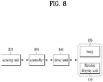
- a mobile terminal including a body varying in size, a flexible display including a first display located on a front side of the body, a second display located on one lateral side of the body and a third display located on a rear side of the body, a drive unit expanded in a direction of the one lateral side of the body to expand a size of the first display, a sensing unit detecting an input signal, and a controller configured to, based on the input signal matching a preset pattern, release locking of the mobile terminal and control the drive unit to expand the size of the first display , wherein the input signal may include a knock code through a user's touch input onto the flexible display and wherein the flexible display may have the third display contracted when the first display is expanded.
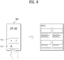
- the knock code may include a touch input of consecutively knocking a prescribed region of the flexible unit within a reference time.
- the prescribed region may include a plurality of divided grids and the knock code may be a password generated from a user-set sequence of the grids from each of which a touch input is detected
- the prescribed region may be located on the second display.
- the knock code may include a touch input of consecutively knocking the prescribed region of each of the first and third displays within a reference time.
- the controller may display a guide text indicating that the size of the first display is expanded on the first display.
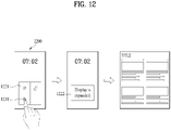
- the input signal may include the knock code and a touch & drag in a specific direction with respect to the knock code and the controller may release the locking of the mobile terminal, expand the size of the first display, and execute an application for the notification on the first display.
- the specific direction may be the same as a direction in which the first display is expanded.
- the notification may be related to at least one of a phone call, a message, or a Social Network Service (SNS).
- SNS Social Network Service
- the input signal may include a knock code detected from the second display and the controller may release the locking of the mobile terminal, expand the size of the first display, and execute an application for the notification on the first display.
- the first display of the flexible display may be expandable into one of a plurality of sizes and based on inputting the knock code, the controller may display a selection menu for selecting any one of a plurality of the sizes on the first display.
- the selection menu may be displayed on a region having the knock code inputted thereto by the user in the first display.
- a mobile terminal including a body varying in size, a flexible display including a first display located on a front side of the body, a second display located on one lateral side of the body and a third display located on a rear side of the body, a drive unit expanded in a direction of the one lateral side of the body to expand a size of the first display, a sensing unit detecting an input signal, and a controller configured to expand the size of the first display and display a standby screen on the first display based on the input signal matching a preset pattern, wherein the flexible display may have the third display contracted when the first display is expanded.
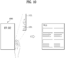
- the input signal may include a combination of a knock code through a user's touch input on to the flexible display and a user's gesture action.
- the knock code may include a touch input of consecutively knocking a prescribed region of the flexible display within a reference time.
- the user's gesture action may include a swipe action performed on one side direction of the mobile terminal and the one side direction may be the same as a direction in which the first display is expanded.
- the input signal may include a knock code of consecutively knocking a prescribed region of the second display within a reference time.
- the input signal may include a swipe action performed in one side direction after fingerprint recognition.
- the controller may display information for guiding the swipe action on the first display.
- the input signal may include fingerprint recognition.
- the mobile terminal capable of extending the display and the method for controlling the same may be provided.
- the mobile terminal when a preset knock code is inputted, the mobile terminal is unlocked and the display is expanded, so that a user may immediately use the expanded display.
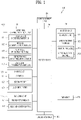
- FIG. 1 is a block diagram of a mobile terminal in accordance with the present disclosure.
- the mobile terminal 100 is shown having components such as a wireless communication unit 110, an input unit 120, a sensing unit 140, an output unit 150, an interface unit 160, a memory 170, a controller 180, and a power supply unit 190.
- a wireless communication unit 110 configured with several commonly implemented components. It is understood that implementing all of the illustrated components is not a requirement, and that greater or fewer components may alternatively be implemented.
- the wireless communication unit 110 typically includes one or more modules which permit communications such as wireless communications between the mobile terminal 100 and a wireless communication system, communications between the mobile terminal 100 and another mobile terminal, communications between the mobile terminal 100 and an external server. Further, the wireless communication unit 110 typically includes one or more modules which connect the mobile terminal 100 to one or more networks.
- the wireless communication unit 110 includes one or more of a broadcast receiving module 111, a mobile communication module 112, a wireless Internet module 113, a short-range communication module 114, and a location information module 115.
- the broadcast receiving module 111 is typically configured to receive a broadcast signal and/or broadcast associated information from an external broadcast managing entity via a broadcast channel.
- the broadcast channel may include a satellite channel, a terrestrial channel, or both.
- two or more broadcast receiving modules 111 may be utilized to facilitate simultaneously receiving of two or more broadcast channels, or to support switching among broadcast channels.
- the mobile communication module 112 can transmit and/or receive wireless signals to and from one or more network entities.
- a network entity include a base station, an external mobile terminal, a server, and the like.
- Such network entities form part of a mobile communication network, which is constructed according to technical standards or communication methods for mobile communications (for example, Global System for Mobile Communication (GSM), Code Division Multi Access (CDMA), CDMA2000(Code Division Multi Access 2000), EV-DO(Enhanced Voice-Data Optimized or Enhanced Voice-Data Only), Wideband CDMA (WCDMA), High Speed Downlink Packet access (HSDPA), HSUPA(High Speed Uplink Packet Access), Long Term Evolution (LTE) , LTE-A(Long Term Evolution-Advanced), and the like).
- GSM Global System for Mobile Communication
- CDMA Code Division Multi Access
- CDMA2000 Code Division Multi Access 2000
- EV-DO Enhanced Voice-Data Optimized or Enhanced Voice-Data Only
- WCDMA Wideband CDMA
- HSDPA High Speed
- Examples of wireless signals transmitted and/or received via the mobile communication module 112 include audio call signals, video (telephony) call signals, or various formats of data to support communication of text and multimedia messages.
- the wireless Internet module 113 is configured to facilitate wireless Internet access. This module may be internally or externally coupled to the mobile terminal 100. The wireless Internet module 113 may transmit and/or receive wireless signals via communication networks according to wireless Internet technologies.
- wireless Internet access examples include Wireless LAN (WLAN), Wireless Fidelity (Wi-Fi), Wi-Fi Direct, Digital Living Network Alliance (DLNA), Wireless Broadband (WiBro), Worldwide Interoperability for Microwave Access (WiMAX), High Speed Downlink Packet Access (HSDPA), HSUPA(High Speed Uplink Packet Access), Long Term Evolution (LTE), LTE-A(Long Term Evolution-Advanced), and the like.
- the wireless Internet module 113 may transmit/receive data according to one or more of such wireless Internet technologies, and other Internet technologies as well.
- the wireless Internet module 113 when the wireless Internet access is implemented according to, for example, WiBro, HSDPA,HSUPA, GSM, CDMA, WCDMA, LTE, LTE-A and the like, as part of a mobile communication network, the wireless Internet module 113 performs such wireless Internet access. As such, the Internet module 113 may cooperate with, or function as, the mobile communication module 112.
- the short-range communication module 114 is configured to facilitate short-range communications. Suitable technologies for implementing such short-range communications include BLUETOOTHTM, Radio Frequency IDentification (RFID), Infrared Data Association (IrDA), Ultra-WideBand (UWB), ZigBee, Near Field Communication (NFC), Wireless-Fidelity (Wi-Fi), Wi-Fi Direct, Wireless USB(Wireless Universal Serial Bus), and the like.
- the short-range communication module 114 in general supports wireless communications between the mobile terminal 100 and a wireless communication system, communications between the mobile terminal 100 and another mobile terminal 100, or communications between the mobile terminal and a network where another mobile terminal 100 (or an external server) is located, via wireless area networks.
- One example of the wireless area networks is a wireless personal area networks.
- the location information module 115 is generally configured to detect, calculate, derive or otherwise identify a position of the mobile terminal.
- the location information module 115 includes a Global Position System (GPS) module, a Wi-Fi module, or both. If desired, the location information module 115 may alternatively or additionally function with any of the other modules of the wireless communication unit 110 to obtain data related to the position of the mobile terminal.
- GPS Global Position System
- a position of the mobile terminal may be acquired using a signal sent from a GPS satellite.
- Wi-Fi module a position of the mobile terminal can be acquired based on information related to a wireless access point (AP) which transmits or receives a wireless signal to or from the Wi-Fi module.
- AP wireless access point
- the input unit 120 includes a camera 121 for obtaining images or video, a microphone 122, which is one type of audio input device for inputting an audio signal, and a user input unit 123 (for example, a touch key, a push key, a mechanical key, a soft key, and the like) for allowing a user to input information.
- Data for example, audio, video, image, and the like
- controller 180 may analyze and process data (for example, audio, video, image, and the like) according to device parameters, user commands, and combinations thereof.
- Such cameras 121 may process image frames of still pictures or video obtained by image sensors in a video or image capture mode. The processed image frames can be displayed on the display unit 151 or stored in memory 170. In some cases, the cameras 121 may be arranged in a matrix configuration to permit a plurality of images having various angles or focal points to be input to the mobile terminal 100. As another example, the cameras 121 may be located in a stereoscopic arrangement to acquire left and right images for implementing a stereoscopic image.
- the microphone 122 is generally implemented to permit audio input to the mobile terminal 100.
- the audio input can be processed in various manners according to a function being executed in the mobile terminal 100.
- the microphone 122 may include assorted noise removing algorithms to remove unwanted noise generated in the course of receiving the external audio.
- the user input unit 123 is a component that permits input by a user. Such user input may enable the controller 180 to control operation of the mobile terminal 100.
- the user input unit 123 may include one or more of a mechanical input element (for example, a key, a button located on a front and/or rear surface or a side surface of the mobile terminal 100, a dome switch, a jog wheel, a jog switch, and the like), or a touch-sensitive input, among others.
- the touch-sensitive input may be a virtual key or a soft key, which is displayed on a touch screen through software processing, or a touch key which is located on the mobile terminal at a location that is other than the touch screen.
- the virtual key or the visual key may be displayed on the touch screen in various shapes, for example, graphic, text, icon, video, or a combination thereof.
- the sensing unit 140 is typically implemented using one or more sensors configured to sense internal information of the mobile terminal, the surrounding environment of the mobile terminal, user information, and the like.
- the sensing unit 140 may alternatively or additionally include other types of sensors or devices, such as a proximity sensor 141 and an illumination sensor 142, a touch sensor, an acceleration sensor, a magnetic sensor, a G-sensor, a gyroscope sensor, a motion sensor, an RGB sensor, an infrared (IR) sensor, a finger scan sensor, a ultrasonic sensor, an optical sensor (for example, camera 121), a microphone 122, a battery gauge, an environment sensor (for example, a barometer, a hygrometer, a thermometer, a radiation detection sensor, a thermal sensor, and a gas sensor, among others), and a chemical sensor (for example, an electronic nose, a health care sensor, a biometric sensor, and the like), to name a few.
- the mobile terminal 100 may be configured to utilize information obtained from sensing unit
- the output unit 150 is typically configured to output various types of information, such as audio, video, tactile output, and the like.
- the output unit 150 is shown having a display unit 151, an audio output module 152, a haptic module 153, and an optical output module 154.
- the display unit 151 may have an inter-layered structure or an integrated structure with a touch sensor in order to facilitate a touch screen.
- the touch screen may provide an output interface between the mobile terminal 100 and a user, as well as function as the user input unit 123 which provides an input interface between the mobile terminal 100 and the user.
- the audio output module 152 is generally configured to output audio data. Such audio data may be obtained from any of a number of different sources, such that the audio data may be received from the wireless communication unit 110 or may have been stored in the memory 170. The audio data may be output during modes such as a signal reception mode, a call mode, a record mode, a voice recognition mode, a broadcast reception mode, and the like. The audio output module 152 can provide audible output related to a particular function (e.g., a call signal reception sound, a message reception sound, etc.) performed by the mobile terminal 100. The audio output module 152 may also be implemented as a receiver, a speaker, a buzzer, or the like.
- a haptic module 153 can be configured to generate various tactile effects that a user feels, perceive, or otherwise experience.
- a typical example of a tactile effect generated by the haptic module 153 is vibration.
- the strength, pattern and the like of the vibration generated by the haptic module 153 can be controlled by user selection or setting by the controller. For example, the haptic module 153 may output different vibrations in a combining manner or a sequential manner.
- An optical output module 154 can output a signal for indicating an event generation using light of a light source. Examples of events generated in the mobile terminal 100 may include message reception, call signal reception, a missed call, an alarm, a schedule notice, an email reception, information reception through an application, and the like.
- the interface unit 160 serves as an interface with various types of external devices that can be coupled to the mobile terminal 100.
- the interface unit 160 may include any of wired or wireless ports, external power supply ports, wired or wireless data ports, memory card ports, ports for connecting a device having an identification module, audio input/output (I/O) ports, video I/O ports, earphone ports, and the like.
- the mobile terminal 100 may perform assorted control functions associated with a connected external device, in response to the external device being connected to the interface unit 160.
- the memory 170 is typically implemented to store data to support various functions or features of the mobile terminal 100.
- the memory 170 may be configured to store application programs executed in the mobile terminal 100, data or instructions for operations of the mobile terminal 100, and the like. Some of these application programs may be downloaded from an external server via wireless communication. Other application programs may be installed within the mobile terminal 100 at time of manufacturing or shipping, which is typically the case for basic functions of the mobile terminal 100 (for example, receiving a call, placing a call, receiving a message, sending a message, and the like). It is common for application programs to be stored in the memory 170, installed in the mobile terminal 100, and executed by the controller 180 to perform an operation (or function) for the mobile terminal 100.
- the controller 180 typically functions to control overall operation of the mobile terminal 100, in addition to the operations associated with the application programs.
- the controller 180 may provide or process information or functions appropriate for a user by processing signals, data, information and the like, which are input or output, or activating application programs stored in the memory 170.
- the controller 180 may be implemented to control a predetermined number of the components mentioned above in reference with FIG. 1A. Moreover, the controller 180 may be implemented to combinedly operate two or more of the components provided in the mobile terminal 100 to drive the application programs.
- the power supply unit 190 can be configured to receive external power or provide internal power in order to supply appropriate power required for operating elements and components included in the mobile terminal 100.
- the power supply unit 190 may include a battery, and the battery may be configured to be embedded in the terminal body, or configured to be detachable from the terminal body.
- Some or more of the components may be operated cooperatively to embody an operation, control or a control method of the mobile terminal in accordance with embodiments of the present disclosure. Also, the operation, control or control method of the mobile terminal may be realized on the mobile terminal by driving of one or more application problems stored in the memory 170.
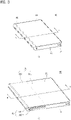
- FIG. 2 is an exploded perspective view of a mobile terminal according to one embodiment.
- FIG. 3 shows perspective views respectively illustrating a first state and a second state viewed from one side of a mobile terminal according to one embodiment.
- FIG. 4 shows rear face views respectively illustrating a first state and a second state of a mobile terminal according to one embodiment.
- FIG. 5 shows cross-sectional views respectively taken along a line A-A and a line B-B of FIG. 3 .
- FIGS. 3 (a) , 4 (a) , and 5 (a) show a first state of the mobile terminal
- FIGS. 3 (b) , 4 (b) , and 5 (b) show a second state of the mobile terminal.
- a mobile terminal 100 in a first state is contracted, and has a smaller size than the mobile terminal 100 in a second state.
- a size of a display unit 151 located disposed on a front face of the mobile terminal 100 also becomes smaller than that of the display unit 151 in the second state.
- the mobile terminal 100 of the first state is expanded in a first direction D1 to be in the second state.
- the size of the mobile terminal 100 and a size of a front face of the display unit 151 are larger than those in the first state.
- a direction in which the mobile terminal 100 and the display 151 thereof are extended or enlarged is referred to as a first direction D1
- a direction in which the mobile terminal 100 and the display 151 thereof are contracted or retracted, or reduce to be converted into the first state from the second state is referred to as a second direction D2
- a direction perpendicular to the first and second directions D1 and D2 is referred to as a third direction.
- the mobile terminal 100 of the present disclosure may be converted from the first state in which the display unit 151 is positioned on the front face of a bar-shaped mobile terminal as shown in FIG. 3 (a) into the second state as shown in FIG. 3 (b) by enlarging a screen thereof.
- the second state an area of the front face of the display unit 151 is enlarged, and an area of a rear face of the display unit 151 is reduced as shown in FIG. 4 (b) . That is, the display unit 151 positioned on a rear face of the mobile terminal 151 in the first state moves to the front face of the mobile terminal 100 in the second state.
- the display unit may use a flexible display 151 that may be bent such that the position of the display unit may be varied.
- the flexible display is a lightweight, unbreakable, and durable display that is built on a thin and flexible substrate that may be bent, crooked, folded, twisted, or rolled while retaining properties of a conventional flat panel display.
- an electronic paper is a display technology to which properties of general ink are applied.
- the electronic paper may be different from the conventional flat panel display in using reflected light.
- the electronic paper may change information using a twisted ball or electrophoresis using a capsule.
- a display region of the flexible display 151 becomes flat.
- the display region may become a curved face.
- information displayed in the deformation state may be visual information output on the curved face.
- Such visual information is implemented by independently controlling light emission of sub-pixels arranged in a matrix.
- the sub-pixel refers to a minimum unit for implementing one color.
- the flexible display 151 may be in a curved state (e.g., a vertically or horizontally curved state) rather than a flat state in the basic state. In this case, when the external force is applied to the flexible display 151, the flexible display 151 may be deformed into the flat state (or a less curved state) or more curved state.
- a curved state e.g., a vertically or horizontally curved state
- the flexible display 151 may be deformed into the flat state (or a less curved state) or more curved state.
- the flexible display 151 may be combined with a touch sensor to implement a flexible touch screen.
- the controller 180 may perform control corresponding to such touch input.
- the flexible touch screen may be configured to detect the touch input in the deformed state as well as in the basic state.
- the touch sensor detects the touch (or touch input) applied on the touch screen using at least one of various touch schemes such as a resistive film scheme, a capacitance scheme, an infrared scheme, an ultrasonic wave scheme, a magnetic field scheme, and the like.
- various touch schemes such as a resistive film scheme, a capacitance scheme, an infrared scheme, an ultrasonic wave scheme, a magnetic field scheme, and the like.
- the touch sensor may be configured to convert a change in pressure applied on a specific portion of the touch screen, capacitance generated at the specific portion, or the like into an electrical input signal.
- the touch sensor may be configured such that a touch object applying a touch on the touch screen may detect touched position and area on the touch sensor, a pressure during the touch, a capacitance during the touch, and the like.
- the mobile terminal 100 may have a deformation detection means for detecting the deformation of the flexible display 151.
- Such deformation detection means may be included in the sensing unit 140 (see FIG. 1 ).
- the deformation detection means may be disposed in the flexible display 151 or a case (first to third frames 101 to 103 to be described later) to detect information related to the deformation of the flexible display 151.
- the information related to the deformation may include a direction in which the flexible display 151 is deformed, a degree of the deformation, a deformed position, a deformed time, an acceleration at which the deformed flexible display 151 is restored, and the like.
- the information related to the deformation may be various information that may be detected due to the bending of the flexible display 151.
- controller 180 may change information displayed on the flexible display 151 or generate a control signal for controlling a function of the mobile terminal 100 based on the information related to the deformation of the flexible display 151 detected by the deformation detection means.
- the state conversion (first or second state) of the flexible display 151 e.g., the size change at the front and rear faces of the mobile terminal 100 of the display unit 151 based on the size change of the mobile terminal 100 may be performed manually by a force applied by the user, but may be not limited to such manual scheme.
- the mobile terminal 100 or the flexible display 151 may be converted into the second state by the user or an application command without the external force applied by the user.
- the mobile terminal 100 may include a driving unit 200 to be described later.
- the flexible display 151 of the present disclosure is bent 180 degrees while being rolled on one of both sides of the mobile terminal 100.
- a portion of the display unit 151 is disposed on the front face of the mobile terminal 100 based on such side, and the other portion thereof is disposed on the rear face of the mobile terminal 100.
- a portion of the display unit 151 located on the front face of the mobile terminal 100 may be fixed to the front face so as not to move. Further, the other portion thereof located on the rear face of the mobile terminal 100 may be movable to the rear face.
- the display unit 151 may be rolled on or released from the side. Accordingly, the portion disposed on the rear face of the mobile terminal 100 moves, so that the size of the portion disposed on the front face of the mobile terminal 100 may be adjusted. Since the area of the flexible display 151 is determined and the flexible display 151 is formed of one continuous body, an area of the portion on the rear face decreases as an area of the portion on the front face increases. Such a display unit 151 may be rolled in a second frame 102, which is movable relative to a first frame 101 to be described later, more correctly, on one of sides of the second frame 102.
- the display unit 151 may be withdrawn or pulled out from or inserted or pushed into the second frame 102 while being rolled in the second frame 102 along a moving direction of the second frame 102 to adjust the area of the display unit 151 on the front face of the mobile terminal 100. Such operation will be described in more detail below along with other relevant components of the mobile terminal 100.
- an antenna is disposed in the case or the housing of the mobile terminal 100, but a portion where the antenna is installed in the case or the housing may be limited because of the flexible display 151 that covers not only the front face of the mobile terminal 100 but also the rear face thereof. For this reason, the antenna may be implemented on the flexible display 151.
- An antenna on display is an antenna in which a transparent film is formed by stacking an electrode layer and a dielectric layer that have patterns engraved thereon, respectively.
- the antenna on display may be implemented thinner than an antenna implemented using a laser direct structuring (LDS) technology using a conventional copper nickel plating scheme, so that the antenna on display may not be exposed to the outside without affecting a thickness.
- the antenna on display may transmit and receive a signal directly to or from the display unit 151. Accordingly, the antenna on display may be used in the mobile terminal 100 in which the display unit 151 is located on the both faces of the mobile terminal 100 as in the present disclosure.
- FIGS. 2 to 5 a detailed configuration of the mobile terminal 100 of the present disclosure will be described in detail below. A following description will be achieved basically with reference to FIG. 2 illustrating an overall configuration.
- FIGS. 3 to 5 are referred to to explain detailed features of corresponding components in the first and second states of the mobile terminal 100.
- the mobile terminal 100 of the present disclosure includes a main frame in which components are mounted, and the main frame of the present disclosure may vary in size in the first direction as shown in FIG. 2 .
- One or more frames move relative to each other, and sizes thereof may vary in the first direction.
- Electronic components are mounted in the main frame, and the flexible display 151 is located out of the main frame.
- the flexible display 151 may be combined in a form surrounding a front face and a rear face of the main frame.
- the main frame may include first to third frames 101 to 103.
- the main frame may include the first frame 101, the second frame 102 moving in the first direction with respect to the first frame 101, and the third frame 103 moving in the first direction with respect to the second frame 102.
- the first frame 101 and the second frame 102 include front portions, a rear portions, and side portions, respectively, and are coupled to each other.
- the mobile terminal 100 may have a hexahedral outer shape by such coupled first and second frames 101 and 102.
- movements of the second and third frames 102 and 103 may be a slide movement.
- the first frame 101 corresponds to a main body of the mobile terminal 100, and may have a space therein for accommodating various components.
- the first frame 101 may accommodate the second frame 102 movably coupled to the first frame 101 in such a space. More specifically, as shown in FIGS. 2 and 5 , the first frame 101 may include a first front portion 1011 disposed at a front portion of the mobile terminal 100 and a first rear portion 1012 and a second rear portion 1013 disposed at a rear portion of the mobile terminal.
- Such first front portion 1011, first rear portion 1012, and second rear portion 1013 may be respectively formed of plate-shaped members that are generally flat.
- the first rear portion 1012 and the second rear portion 1013 may be respectively formed of separate members coupled to each other or may be formed of one member as shown.
- the first front portion 1011 and the first rear portion/second rear portion 1012 and 1013 may be spaced apart from each other at a predetermined spacing to define a predetermined space therebetween, and may be connected to each other by a side portion 1014.
- the controller 180 and the power supply unit 190 may be accommodated as components of the mobile terminal 100 in the space in the first frame 101.
- the controller 180 may be a circuit board including a processor and an electronic circuit for controlling the operation of the mobile terminal, and the power supply unit 190 may be a battery and related components.
- the second frame 102 and the driving unit 200 to be described later may also be accommodated in the first frame 101.
- the display unit 151 has the continuous body, and thus, may be disposed on both the front face and the rear face of the mobile terminal 100 while being rolled in the mobile terminal 100.
- the display unit 151 may include the front face positioned at the front face of the mobile terminal 100, the rear face positioned at the rear face of the mobile terminal 100, and the side face positioned between the front face and the rear face thereof and surrounding the side face of the mobile terminal.
- the front face and the rear face of the display unit 151 are flat, and the side face of the display unit 151 may form a curved face.
- the flexible display 151 may be damaged when being bent.
- the flexible display 151 may be formed to be bent with a predetermined curvature.
- the display unit 151 may be divided into a fixed portion and a variable portion.
- the fixed portion means a portion fixed to the frame. Because of being fixed to the frame, the fixed portion maintains a constant shape without changing a bending degree.
- the variable portion means a portion in which a bending angle or a position of the bent portion changes.
- the variable portion in which the position or bending angle of the bent portion changes requires a structure for supporting a rear face of the variable portion in response to the change.
- a first region of the display unit 151 may be coupled to the first front portion 1011 corresponding to the front face of the mobile terminal 100.
- various physical input units 120 for manipulation of the mobile terminal 100 and sensing units 140 may be located on the first rear portion 1012, and the display unit 151 may be disposed only on the second rear portion 1013. Since the first rear portion 1012 does not overlap the flexible display 151 regardless of the state of the mobile terminal, and is always exposed to the outside, the input unit 120 such as various buttons, switches, the camera 121, and a flash, and the sensing unit 140 such as a proximity sensor 141 may be arranged on the first rear portion 1012. In a conventional bar-shaped terminal, a display unit is provided only on a front face of the terminal.
- a main camera is placed on a rear face of the terminal in order for the user to capture an object at an opposite side while looking through the display unit.
- an additional auxiliary camera is required to be disposed on the front face of the terminal in order for the user to capture himself or herself while viewing himself or herself through the display unit.
- the display unit 151 is positioned both the front face and the rear face of the mobile terminal 100 of the present disclosure. Therefore, when the user captures himself or herself, a display unit on the same face as the camera 121, that is, the portion of the display 151 on the rear face of the mobile terminal 100 in the drawing may be used. Further, when the user captures the object on the opposite side of the user, a display unit on the opposite face of the camera 121, that is, the portion of the display unit 151 on the front face of the mobile terminal 100 in the drawing may be used. For this reason, the mobile terminal 100 may capture the object on the opposite side of the user and capture the user using the single camera 121.
- the camera may include a plurality of cameras having different angles of view, such as wide angle, super wide angle, and telephotographic cameras.
- a proximity sensor sound output unit may be positioned on the first rear portion 1012, and an antenna 116 may be installed on the first rear portion 1012.
- the side portion 1014 may extend along edges of the first front portion 1011 and the first rear portion/second rear portion 1012 and 1013 to surround the first frame 101, and may form the outer shape of the mobile terminal 100.
- the second frame 102 since the second frame 102 is accommodated in the first frame 101 and is movably coupled thereto, in order to allow the movement of the second frame 102 relative to the first frame 101, a portion of the first frame 101 needs to be opened. As shown in FIG. 2 , as an example, the second frame 102 is movably coupled to one of both side portions of the first frame 101, so that the side portion 1014 may not be formed on the same side portion, and thus, the portion of the first frame 101 may be opened.
- the first frame 101 may include a substantially closed first side portion 101a and a second side portion 101b, which is disposed to be opposite to the first side portion 101a and is opened.
- the side portion 1014 is exposed to the outside of the mobile terminal 100, so that an interface unit 160 for connecting a supply port or an ear jack, the user input unit 120 such as a volume button, or the like may be disposed on the side portion 1014.
- the side portion 1014 may serve as an antenna.
- the second rear portion 1013 of the first frame 101 may be covered by the display unit, but may be disposed on the front face of the display unit using a transparent material.
- the second frame 102 may include a second front portion 1021 disposed at the front portion of the mobile terminal 100 and a third rear portion 1022 disposed at the rear portion of the mobile terminal 100.
- the second front portion 1021 and the third rear portion 1023 may be formed of plate-shaped members that are generally flat.
- the second frame 102 also accommodates various components, and should not interfere with the components accommodated in the first frame 101 during the movement. Accordingly, the second front portion 1021 and the third rear portion 1022 may be coupled to each other in a state of being spaced apart from each other to define a predetermined space therebetween, and may have shapes that do not interfere with the components in the first frame 101.
- the display unit 151 may be bent 180 degrees while being rolled in the second frame 102 to be disposed on both the front face and the rear face of the mobile terminal 100.
- the second frame 102 may include a roller 1028 rotatably disposed therein.
- the roller 1028 may be disposed at any position inside the second frame 102.
- the display unit 151 should be spread flat on the front face and the rear face of the mobile terminal 100 to provide a good quality screen to the user. Further, for such spread, a proper tension should be provided on the display unit 151.
- the roller 1028 may be disposed at a first directional end of the second frame 102.
- the roller 1028 may extend in the third direction, and may be rotatably coupled to the second frame 102.
- the display unit 151 may be rolled around the roller 1028 while being gently bent with a predetermined curvature.
- the flexible display 151 may include a first face on which a video is output and exposed to the outside and an inner face facing the frame at the opposite side.
- the roller 1028 may be installed to rotate freely in the second frame 102 while being in contact with the inner face of the display unit 151. Accordingly, the roller 1028 may actually move the display unit 151 in a lateral direction of the mobile terminal 100, that is, in a direction perpendicular to a longitudinal direction.
- the display unit 151 moves to the front face or the rear face of the mobile terminal 100 in different directions (e.g., the first direction D1 or the second direction D2) relative to the second frame 102.
- the roller 1028 may guide such movement while rotating.
- the roller 1028 is disposed on a first side portion 102a of the second frame 102, and the first side portion 102a actually corresponds to an outermost side portion of the mobile terminal 100.
- the display unit 151 rolled on the roller 1028 may be damaged.
- the second frame 102 may include a side frame 1024 disposed on the first side portion 102a.
- the side frame 1024 extends in the longitudinal direction of the second frame 102 to cover the first side portion 102a, thereby protecting the roller 1028 and the display unit 151 rolled thereon. That is, the side frame 1024 covers the side face of the display unit 151, and the side face thereof is located in the third region.
- the first to third regions are at specified positions on the flexible display and do not change in size or position, but the sizes of the front face and the rear face, and the position of the side face are determined based on the state of the main frame.
- the first region and the second region correspond to the fixed portion described above.
- the third region corresponds to the variable portion described above, and may vary in position depending on the state of the mobile terminal. Because the side face is rolled by the roller, the side face is bent with the predetermined curvature, and an inner face of the side frame may include a curved face corresponding to the curvature of the side face.
- the second frame 102 may have the substantially closed first side portion 102a, and the side frame 1024 may substantially form the outer shape of the mobile terminal 100 together with the side face 1014 of the first frame 101.
- the second frame 102 may include a second side portion 102b that is disposed opposite the first side portion 102a to minimize interference with the components within the first frame 101 during the movement, and is opened.
- Such a second frame 102 is movably coupled to the first frame 101, and thus may slide in the predetermined first or second direction D1 or D2 relative to the first frame 101. More specifically, the second frame 102 may be movably coupled to the first frame 101 through the side portion of the first frame 101, more precisely, through the opened second side portion 101b, as shown. More specifically, the second side portion 102b of the second frame is disposed relatively adjacent to the first side portion 101a of the first frame 101 which is closed. Accordingly, the first side portion 102a of the second frame may be disposed to be opposite to the first side portion 101a. Accordingly, the second side portion 102b is inserted into the first frame 101 through the side portion of the first frame, that is, the second side portion 101b thereof.
- the first side portion 102a is not inserted into the first frame 101 but is always located outside the first frame 101, thereby forming the outer shape of the mobile terminal 100 as described above. However, when necessary, such first side portion 102b of the second frame 102 may also be inserted into the first frame 101.
- the second frame 102 may extend from or contract to the first frame 101 in a direction perpendicular to the longitudinal direction of the mobile terminal 100 or the first frame 101. That is, the first and second directions D1 and D2 may basically be directions perpendicular to the longitudinal direction of the mobile terminal 100 or the first frame 101. Further, the first and second directions D1 and D2 may also be described as the lateral direction or the horizontal direction of the mobile terminal 100 or the first frame 101. In addition, during the movement in the first direction D1, the second frame 102 extends from the first frame 101. Accordingly, the first direction D1 may be a direction in which the second frame 102 moves away from the first frame 101, that is, moves outwardly of the mobile terminal 100 or the first frame 101.
- the second frame 102 contracts to the first frame 101.
- the second direction D2 is a direction opposite to the first direction D1, so that the second direction D2 may be a direction in which the second frame 102 moves to become closer to the first frame 101, that is, moves inwardly of the mobile terminal 100 or the first frame 101.
- such second frame 102 extends and applies a force to the portion of the display unit 151 disposed on the rear face of the mobile terminal 100, so that the portion of the display unit 151 may be disposed on the front face of the mobile terminal 100, and a region for such additional arrangement may be defined.
- the second frame 102 may convert the mobile terminal 100 into the second state with the display unit 151 with the relatively extended front face by moving in the first direction D1.
- the second frame 102 contracts into an original state thereof, and applies a force to the portion of the display unit 151 disposed on the front face of the mobile terminal 100 to return to the rear face of the mobile terminal 100 again.
- the second frame 102 may convert the mobile terminal 100 into the first state with the display unit 151 with the relatively contracted front face by moving in the second direction D2.
- the second frame 102 selectively exposes the display unit 151 to the front face of the mobile terminal 100 depending on the moving direction (e.g., the first or second direction D1 and D2). Accordingly, the mobile terminal 100 may be converted into the first or second state defined above.
- the second frame 102 may overlap the first frame 101, more precisely, the first front portion 1011 and the first rear portion 1012 thereof so as not to interfere with the first frame 101.
- the display unit 151 may be coupled to and supported by the first front portion 1011 of the first frame 101, as described above. Accordingly, the display unit 151 does not need to be additionally supported by the second front portion 1021 of the second frame 102. Rather, when the second front portion 1021 is interposed between the first front portion 1011 and the display unit 151, the display unit 151 may be deformed or damaged because of friction with the second front portion 1021, which is repeatedly moved.
- the second front portion 1021 may be disposed below the first front portion 1011, as shown in FIG. 5 . That is, a front face of the second front portion 1021 may face the rear face of the first front portion 1011. In addition, the rear face of the first front portion 1011 may be in contact with the front face of the second front portion 1021 to stably support the movement of the second frame 102.
- the third rear portion 1022 of the second frame 102 may be disposed below the second rear portion 1013 of the first frame 101. That is, the front face of the third rear portion 1022 may face the rear face of the second rear portion 1013. In addition, the rear face of the second rear portion 1013 may be in contact with the front face of the third rear portion 1022 to stably support the movement of the second frame 102. Because of such arrangement, the third rear portion 1022 may be exposed to the outside of the first frame, more precisely, of the second rear portion 1013, and may be coupled to the display unit 151.
- the second rear portion 1013 when the second rear portion 1013 is made of a transparent material, the second rear portion 1013 may form an outer shape of the rear face of the mobile terminal.
- the second rear portion 1013 may be positioned rearward of the third rear portion 1022 of the second frame, and the flexible display may be disposed between the second rear portion 1013 and the third rear portion 1022 in the first state.
- the first rear portion 1012 may be implemented using the same member as the second rear portion 1013. That is, the camera 121, the flash or the sensing unit 140, and the like may be arranged by partially coating the plate-shaped member of the transparent glass material to not allow the internal components to be visible and by not coating only a required portion.
- the second frame 102 may expand and contract the size of the mobile terminal 100 itself, particularly the front face of the mobile terminal 100 by the expansion and the contraction in the first and second directions D1 and D2.
- the display unit 151 should move by such extended or reduced front face size to obtain the intended first and second states.
- the display unit 151 may not be moved smoothly to be adapted for the front face of the mobile terminal 100 that is expanded or contracted. For this reason, the display unit 151 may be movably coupled to the second frame 102.
- the display unit 151 may include a first side edge (or side end) 151d disposed on the front face of the mobile terminal 100 and a second side edge 151e opposite to the first side edge 151d and disposed on the rear face of the mobile terminal 100.
- the first side edge 151 may be disposed on the front face of the first frame 101, that is, the front face of the first front portion 1011 thereof, and may be disposed adjacent to the side portion of the mobile terminal 100, that is, the first side portion 101a of the first frame.
- the second side edge 151e is adjacent to the rear face of the mobile terminal 100 and the third rear portion 1022 of the second frame 102, the second side edge 151e may is be coupled the third rear portion 1022 of the second frame 102 to be movable in the first and second directions D1 and D2.
- a third frame 103 may be coupled to the second side edge 151e.
- the third frame 103 may be formed of a plate-shaped member extending in the longitudinal direction of the mobile terminal 100. Accordingly, the third frame 103 may be coupled to the second frame, that is, the third rear portion 1022 thereof to be movable in the first and second directions D1 and D2 instead of the second side edge 151e.
- the second frame 102 may include a slot 1025 extending in the lateral direction of the mobile terminal 100 or the second frame 102, that is, the direction perpendicular to the longitudinal direction thereof.
- the third frame 103 may be stably moved while being guided by the slot 1025.
- the third frame 103 may include, for example, a projection inserted into the slot 1025 for the movement along the slot 1025.
- the display unit 151 may include a first region 1511 extending from one side thereof, that is, the first side edge 151d toward the second side edge 151e by a predetermined length, and a second region 1512 disposed opposite the first region 1511, and extending from the second side edge 151e toward the first side edge 151d by a predetermined length.
- the display unit 151 may include a third region 1513 disposed between the first and second regions 1511 and 1512.
- Such first to third regions 1511, 1512, and 1513 may be connected to each other, and may form a continuous body of the display unit 151.
- the first region 1511 may be fixed so as not to move to the front face of the mobile terminal 100, and the second region 1512 may be provided to be movable on the rear face of the mobile terminal.
- Such configuration of the display unit 151 will be described in more detail below.
- the first region 1511 may be disposed on the front face of the mobile terminal 100, more specifically, the first frame 101, that is, on the front face of the first front portion 1011.
- the first region 1511 is fixed to the first frame 101, that is, the front face of the first front portion 1011 so as not to be moved during the movement of the second frame 102, and thus, the first region 1511 may always be exposed to the front face of the mobile terminal 100.
- the third region 1513 may be adjacent to the first region 1511, and may extend into the second frame 102 and rolled on the roller 1028.
- the third region 1513 may consecutively extend out of the second frame 102 again and partially cover the second frame 102, that is, the rear face of the third rear portion 1022.
- the second frame 102 that is, the third rear portion 1022, is adjacent to the first frame 101, that is, the second rear portion 1013 and together forms the rear case of the mobile terminal 100, so that it may be described that the third region 1513 is also disposed on the rear face of the first frame 101.
- the second region 1512 may be adjacent to the third region 1513 and may be disposed on the rear face of the mobile terminal 100, more specifically, on the second frame, that is, the rear face of the third rear portion 1022 thereof.
- the second region 1512 may be coupled to the third frame 103 without being directly coupled to the second frame 102.
- the slot 1025 extending in the lateral direction (e.g., the direction perpendicular to the longitudinal direction of the mobile terminal 100) to the second frame 102, that is, to the third rear portion 1022 is defined.
- the third frame 103 may move along the slot 1025.
- the slot 1025 is defined in the rear face of the second frame 102, but may be defined in the side face of the second frame 102.
- the second region 1512 may move in the first or second direction D1 or D2 with respect to the second frame 102 together with the third frame 103, the movement of the second region 1512 may be restricted within the rear face of the mobile terminal 100 by the slot 1025. That is, the second region 1512 does not move out of the second frame 102 even when the second frame 102 is extended or contracted, and may move along the slot 1025 within the second frame 102 by the extended or contracted distance of the second frame 102. Accordingly, the second region 1512 may always be exposed to the rear face of the mobile terminal 100.
- the first region 1511 may be disposed on the front face of the mobile terminal 100 and may be always exposed to the front face regardless of the movement of the second frame 102
- the second region 1512 may be disposed on the rear face of the mobile terminal 100 and may be always exposed to the rear face regardless of the movement of the second frame 102
- the third region 1513 may be disposed between the first and second regions 1511 and 1512, and may be selectively placed on the front face or the rear face of the mobile terminal 100 depending on the moving directions D1 and D2 of the second frame 102.
- the second rear portion 1013 of the first frame 101 is covered by the second and third regions 1512 and 1513 and the third rear portion 1022 of the display unit 151 in the first state, but the third region 1513 moves to the front face of the mobile terminal 100 in the second state, and the third rear portion 1022 also moves in the first direction D1, so that the mobile terminal 100 may be exposed to the outside.
- the second front portion 1021 of the second frame 102 is disposed below the first front portion 1011 of the first frame 101 in the first state, but is moved out of the first frame 101 and supports the third region 1513 of the display unit 151 disposed on the front face of the mobile terminal 100 in the second state.
- first and second regions 1511 and 1512 are always respectively arranged on the front face and the rear face of the mobile terminal 100, curvatures of the first region 1511 and the second region 1512 do not change, and the first region 1511 and the second region 1512 may be maintained in a flat basic state.
- the third region 1513 may be rolled on the roller 1028 and bent in the second frame 102. When converting from the first state to the second state, the third region 1513 may extend from the second frame 102 to the front face of the mobile terminal 100 while being rolled on the roller 1028 in one direction.
- the third region 1513 may be retracted from the front face of the mobile terminal 100 to the second frame 102 while being rolled on the roller 1028 in the opposite direction, and at the same time, may return to the rear face of the mobile terminal 100 from the second frame 102.
- a specific location of the foldable mobile terminal in a form of being spread like a book is easily damaged because only the specific location is folded repeatedly.
- the deformed portion of the flexible display 151 that is, a portion rolled on the roller 1028, may vary based on the first and second states of the mobile terminal 100, that is, the movement of the second frame 102. Accordingly, the mobile terminal 100 of the present disclosure may significantly reduce deformation and fatigue repeatedly applied to a specific portion of the display unit 151, thereby preventing damage to the display unit 151.
- the state conversion may be performed manually by the user, and an operation of the mobile terminal 100 during such manual state conversion will be described.
- operations of the first to third frames 101 to 103 and the display unit 151 which will be described below, may be performed in the same manner when a power source other than a user's force is used, for example, when the driving unit 200 to be described below is applied.
- the second frame 102 is fully retracted into the first frame 102 in the first state. Therefore, only the first region 1511 of the display unit 151 fixed to the front face of the first frame 101 may be exposed to the front face of the mobile terminal 100. Such first region 1511 may be fixed and supported to the first frame 101, that is, the first front portion 1011 thereof. In addition, a major portion of the third region 1513 may be disposed on the rear face of the mobile terminal 100 together with the second region 1512, and the third region 1513 may be disposed in the second frame 102 while being partially rolled on the roller 1028.
- the third region 1513 of the rear face of the mobile terminal 100 may be supported by the second frame, that is, the third rear portion 1022 thereof.
- the second region 1512 may be fixed by the third frame 103 disposed on the second frame (e.g., the third rear portion 1022) and may be movably coupled to the second frame 1012.
- the mobile terminal 100 may be converted into the second state.
- the second frame 102 may extend from the first frame 101 by the movement in the first direction D1, and may increase the overall size of the mobile terminal 100, in particular, the front face thereof.
- the second frame 102 may apply a force, that is, a tension, to the display unit 151 in the first direction D1.
- the display unit 151 is fixed to the first frame 101 but is coupled to the second frame 102 to be movable using the third frame 103, so that the force applied by the second frame 102 allows the third region 1513 to be rolled out from the roller 1028 of the second frame 102 to the front face of the mobile terminal 100. That is, the third region 1513 may be withdrawn (or pulled out) from the second frame 102 or extend to (or move out of) the second frame 102. At the same time, the third region 1513, particularly, the portion located on the rear face of the third region 1513 may be rolled into the roller 1028 of the second frame 102 from the rear face, or may be inserted (or pushed in), retracted, or moved into the second frame 102.
- the third region 1513 is withdrawn from the second frame 102 to the front face of the mobile terminal 100, and a portion of the third region 1513 may be disposed in the second frame 102 while still being rolled on the roller 1028.
- the second region 1512 may also move in the first direction D1 with respect to the second frame 102 together with the third frame 103.
- the second region 1512 and the third frame 103 may be constrained to the second frame 102 and move in the first direction D1 with respect to the first frame 101 together with the second frame 102.
- the second region 1512 and the third frame 103 may move in the first direction D1 relative to the first frame 101 as well as the second frame 102, and accordingly, move a distance longer than the moved distance of the second frame 102.
- the third region 1513 may be smoothly extended to the front face of the mobile terminal 100.
- the movement of the second region 1512 and the third frame 103 in the first direction D1 may be performed simultaneously with the movement of such third region 1512 and second frame 102 in the first direction D1 to be proportional to the movement of third region 1513 and second frame 102.
- the first and third regions 1511 and 1513 may be arranged on the front face of the mobile terminal 100, and only the second region 1512 may be disposed on the rear face of the mobile terminal 100.
- Such first and third regions 1511 and 1513 may be supported by the first frame (e.g., the first front portion 1011 thereof) and the second frame (e.g., the second front portion 1021 thereof).
- the second frame 102 e.g., the third rear portion 1022 thereof exposes the second rear portion 1013 of the first frame while extending in the first direction D1, and supports the moving third region 1513. Therefore, in the second state, the mobile terminal 100 may have the extended front face display unit 151.
- the mobile terminal 100 may again return into the first state as shown in FIGS. 3A , 4A , and 5A .
- the second frame 102 may be contracted to the first frame 101 by the movement in the second direction D2, and may reduce the overall size of the mobile terminal 100, particularly the front face thereof.
- the movement of the display unit 151 during such movement of the second frame 102 may be performed in a reverse order of the movement in the first direction D1 described above.
- the third region 1513 may be rolled from the front face of the mobile terminal 100 into the roller 1028 of the second frame 102, or may be inserted, retracted, or moved into the second frame 102.
- the third region 1513 may be rolled, withdrawn, extended, or moved out of the roller 1028 of the second frame 102 to the rear face of the mobile terminal 100. Not the entirety of the third region 1513 may be withdrawn from the second frame 102 to the rear face of the mobile terminal 100, and the portion of the third region 1513 may still be placed in the second frame 102 while still being rolled on the roller 1028.
- the second region 1512 may also move in the second direction D2 with respect to the second frame 102 together with the third frame 103.
- the second region 1512 and the third frame 103 may be constrained to the second frame 102 to move in the second direction D2 with respect to the first frame 101 together with the second frame 102.
- the second region 1512 and the third frame 103 may move relatively in the second direction D2 with respect to not only the second frame 102 but also the first frame 101.
- the second region 1512 and the third frame 103 may move in the second direction D2 a distance larger than the moved distance of the second frame 102.
- the third region 1513 may be smoothly returned to the rear face of the mobile terminal 100.
- the movements of the second region 1512 and the third frame 103 in the second direction D2 may be performed simultaneously with the movements of the third region 1512 and the second frame 102 in the second direction D2 to be proportional to the movements of the third region 1513 and the second frame 102.
- the mobile terminal 100 may be converted into the first state as described above, and may have the display unit 151 with the front face that is relatively reduced in comparison with the second state in the first state.
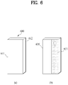
- FIG. 6 is a diagram showing a display provided to a front side, one lateral side and a rear side of a mobile terminal of the present disclosure.
- a mobile terminal 600 of the present disclosure may include a body varying in size and first to third displays 611 to 613 located on the body.
- the first display 611 may be located on a front side of the mobile terminal 600 and the second display 612 may be located on one lateral side of the mobile terminal 600.
- the body is expanded in a direction of the one lateral side, and the first display 611 may be expanded together as well.
- the mobile terminal 600 may include the third display 613 located on a rear side of the mobile terminal 600 and a rear part 651 provided with a camera and the like.
- the mobile terminal 600 of the present disclosure includes a mobile terminal of a rollable type in which the third display 613 is reduced as much as the first display 611 is expanded.
- FIG. 7 is a diagram showing a process for expanding a display located on a front side of a mobile terminal.
- a mobile terminal 700 of the present disclosure may have the first display 711 expanded in one lateral side direction.
- the first display 711 may include a fixed part 711a having a fixed size in the first display and a variable part 711b varying for expansion.
- a size of a third display located on a rear side may be variable in response to a variable size of the variable part 711b.
- FIG. 8 is a block diagram to describe a method of controlling a mobile terminal of the present disclosure.
- a mobile terminal of the present disclosure includes a body 850 varying in size, a flexible display 810 including a first display located on a front side of the body 850, a second display located on one lateral side of the body 850 and a third display located on a rear side of the body 850, a drive unit 840 changing a size of the body 850 and a size of the first display, a sensing unit 820 detecting an input signal, and a controller 830 releasing the locking of the mobile terminal if an input signal matches a preset pattern and controlling the drive unit 840 to expand a size of the first display.
- the flexible display 810 is characterized in that a size of the third dos[;au decreases in response to an increasing size of the first display.
- the sensing unit 820 detects an input signal of a preset pattern
- the signal is forwarded to the controller 830, and thus the controller 830 may control the drive unit 840 to change a size of the body 850 and a size of the first display of the flexible display 810.
- the input signal includes a knock code through a user's touch input to the flexible display 810.
- the knock code is characterized in including a touch input of knocking a prescribed region of the flexible display 810 consecutively within a reference time.
- the flexible display 810 may be regarded as playing the same function as the flexible display 151 mentioned in FIG. 3 and FIG. 4 .
- FIG. 9 is a diagram showing a process for performing unlocking and display expansion of a mobile terminal by inputting a knock code.
- the knock code is a touch input of consecutively knocking a prescribed region of a flexible display within a reference time.
- the reference time may be set to a predetermined time at the beginning of the product release, and may be reset later by a user.
- the prescribed region may include a region including a plurality of divided grids on a display of a mobile terminal 900.
- knock code individual regions on a plurality of grids are touched and a sequence of the touched grids may become a password to form a pattern.
- present disclosure is non-limited by such a pattern and may include various knock code patterns that can be easily derived by those skilled in the art.
- FIG. 10 is a diagram showing a process for performing unlocking and display expansion of a mobile terminal by inputting a knock code onto a display located on one lateral side of a mobile terminal.
- a mobile terminal 1000 of the present disclosure may include a second display on a lateral side part in a direction in which a first display located on a front side is expanded.
- the locking release (i.e., unlocking) and display expansion of the mobile terminal 1000 can be performed through a knock code 1131.
- a region to which the knock code 1031 is inputted corresponds to a prescribed region 1021 of a second display located on a lateral side of the mobile terminal 1000, and the region may include a plurality of divided grids.
- FIG. 11 is a diagram showing a process for performing unlocking and display expansion of a mobile terminal by inputting a knock code onto a display located on front and rear sides of a mobile terminal.
- a mobile terminal 1100 of the present disclosure may include a first display located on a front side and a third display located on a rear side.
- a user performs a knock code action on a prescribed region of each of the displays, thereby expanding the first display located on the front side of the mobile terminal 100 as soon as releasing the locking.
- FIG. 11 in combination of a first knock code 1131 performed on the first display of the front side and a second knock code 1132 performed on the second display of the rear side, the unlocking of the mobile terminal 1100 and display expansion can be achieved.
- FIG. 12 is a diagram showing that a guide text is displayed on a display when the display of a mobile terminal is expanded by a knock code.
- a knock code 1231 when a user inputs a knock code 1231 to a prescribed region 1221 on a display of a mobile terminal 1200 of the present disclosure and the knock code 1231 matches a preset pattern, the locking of the mobile terminal 1200 may be released and the display may be expanded.
- a guide text 1222 indicating that the display is expanded is displayed on the display, thereby providing the user with convenience.
- FIG. 13 is a diagram showing a process for when a notification is received by a mobile terminal, performing unlocking and display expansion of a mobile terminal through a knock code and a gesture action with respect to the notification.
- a mobile terminal 1300 may receive a notification 1361 related to a phone call, a message or a Social Network Service (SNS) in a locked state.
- SNS Social Network Service
- locking is released and a process for executing an application corresponding to the notification by clicking the corresponding notification is performed.
- a display is expandable like the mobile terminal 1300 of the present disclosure, a process for selecting whether to expand a display may be performed additionally.
- unlocking, display expansion and application execution for the notification 1361 may be performed by a knock code 1331 and a gesture action 1332 with respect to the notification 1361 only.
- the knock code 1331 may be separately set by a user, or may be basically set as a simple knock code when the product is shipped.
- the knock code is set by touching the notification 1361 twice within a predetermined time, and then the above functions may be performed by the gesture action1332.
- the gesture action 1332 may include a touch & drag action after the input of the knock code 1331.
- functions (unlocking, display expansion, and application for the notification 1361) described in FIG. 13 may be executed by performing touch & drag in a direction in which a first display of the mobile terminal 1300 is expanded after the knock code 1331.
- FIG. 14 is a diagram showing a process for when a notification is received by a mobile terminal, performing unlocking and display expansion of a mobile terminal through a knock code input to one lateral side of the mobile terminal with respect to the notification.
- FIG. 14 shows a method of utilizing a second display located on one lateral side of a mobile terminal 1400
- FIG. 13 shows a knock code and a gesture action on a notification region.
- a knock code 1431 corresponding to a preset pattern may be inputted to a prescribed region 1421 of a second display.
- the knock code 1431 is the same as the preset pattern, as shown in FIG. 14 , unlocking of the mobile terminal 1400, display expansion and an application for notification 1461 may be executed.
- FIG. 15 is a diagram showing that a separate display size selection menu is provided when a mobile terminal expandable in a plurality of sizes is unlocked by a knock code.
- a size of a first display located on a front side may be expanded as much as a size of a third display located on a rear side is contracted.
- the expansion may go through a plurality of steps, whereby there may be a plurality of expandable sizes of the first display.
- a selection menu 1522 for selecting any one of a plurality of the expandable sizes may be displayed on the display.
- a user may determine a size of an expanded display by selecting any one from the selection menu 1522.
- FIG. 16 is a diagram showing a process for entering a display expansion and standby screen state of a mobile terminal through a knock code and a gesture action.
- a user may just desire to expand a display of a mobile terminal 1600 and enter a standby screen directly without unlocking the mobile terminal 1600.
- a knock code 1631 and a gesture action 1632 are preset, and when an input signal matches a set pattern, a display may be expanded and a standby screen may be displayed on the expanded display.
- the standby screen is in a locked screen state in which the mobile terminal 1600 is still locked, and the mobile terminal 1600 may be unlocked through fingerprint recognition or separate pattern recognition after the display expansion.
- the gesture action 1632 may include a swipe action performed in one direction of the mobile terminal 1600, and the one direction may be the same as or different from a direction in which a first display located on a front surface is expanded.
- unlocking and the display expansion may be possible performed as follows.
- the mobile terminal may perform only the unlocking without the display expansion. That is, the mobile terminal may display a home screen instead of a lock screen without performing the display expansion.
- a user input for unlocking e.g., the knock code, fingerprint recognition, or separate pattern recognition
- the mobile terminal when a user input for unlocking is consecutively performed (or within a prescribed time) after the user input for unlocking has been performed, the mobile terminal performs the display expansion while performing the unlocking, and the home screen may be displayed on the expanded display instead of the lock screen.
- the mobile terminal may display information (e.g., swipe guide graphic) for guiding the gesture to a user in order to notify that the display expansion is possible while performing the unlocking.
- the information for guiding may be displayed when the user input starts to be performed, or may be displayed at a time point when the user input is completed and authenticated.
- the mobile terminal does not necessarily have to have the gesture action. For example, even if only the user input for the unlocking is performed without the gesture action, the mobile terminal may be preconfigured to execute the unlocking together with the display extension.
- FIG. 17 is a diagram showing embodiments of various knock codes for entering a display expansion and standby screen state of a mobile terminal.
- a display extension and a standby screen state may be entered through a knock code 1731 on a second display located on a lateral side of a mobile terminal 1700.
- the knock code may mean an action of consecutively knocking a prescribed region of a display within a reference time.
- the knock code 1731 may be separately set by a user, or may be basically set as a simple knock code when the product is shipped. For example, a knock code may be set by touching twice a prescribed region on the second display unit within a predetermined time.
- a display may be expanded and a standby screen state may be entered.
- a pattern capable of expanding a display and entering a standby screen state may be designated by combining a knock code inputted to a prescribed region of a first display located on a front side and a knock code inputted to a prescribed region of a second display located on a rear side.
Landscapes
- Engineering & Computer Science (AREA)
- Theoretical Computer Science (AREA)
- General Engineering & Computer Science (AREA)
- Physics & Mathematics (AREA)
- Human Computer Interaction (AREA)
- General Physics & Mathematics (AREA)
- Computer Hardware Design (AREA)
- Signal Processing (AREA)
- Mathematical Physics (AREA)
- Multimedia (AREA)
- Computer Networks & Wireless Communication (AREA)
- Telephone Set Structure (AREA)
- Telephone Function (AREA)
Applications Claiming Priority (1)
| Application Number | Priority Date | Filing Date | Title |
|---|---|---|---|
| PCT/KR2019/015543 WO2021095925A1 (ko) | 2019-11-14 | 2019-11-14 | 이동 단말기 및 그 제어 방법 |
Publications (3)
| Publication Number | Publication Date |
|---|---|
| EP4060968A1 true EP4060968A1 (de) | 2022-09-21 |
| EP4060968A4 EP4060968A4 (de) | 2023-07-26 |
| EP4060968B1 EP4060968B1 (de) | 2026-01-28 |
Family
ID=75912450
Family Applications (1)
| Application Number | Title | Priority Date | Filing Date |
|---|---|---|---|
| EP19952939.7A Active EP4060968B1 (de) | 2019-11-14 | 2019-11-14 | Mobiles endgerät und steuerungsverfahren dafür |
Country Status (4)
| Country | Link |
|---|---|
| US (2) | US12081691B2 (de) |
| EP (1) | EP4060968B1 (de) |
| KR (1) | KR102861429B1 (de) |
| WO (1) | WO2021095925A1 (de) |
Families Citing this family (15)
| Publication number | Priority date | Publication date | Assignee | Title |
|---|---|---|---|---|
| KR102826387B1 (ko) * | 2020-07-29 | 2025-06-30 | 삼성전자주식회사 | 슬라이딩 가능한 전자 장치 및 이의 제어 방법 |
| WO2023063681A1 (ko) * | 2021-10-12 | 2023-04-20 | 삼성전자주식회사 | 플렉서블 디스플레이를 구비한 전자 장치 및 플렉서블 디스플레이를 구비한 전자 장치에서 디스플레이 확장 및 축소를 위한 입력 영역 제어 방법 |
| US12399528B2 (en) | 2021-10-12 | 2025-08-26 | Samsung Electronics Co., Ltd. | Electronic device including flexible display and method for controlling input area for expansion and reduction of display in the electronic device |
| WO2023085591A1 (ko) * | 2021-11-10 | 2023-05-19 | 삼성전자주식회사 | 플렉서블 디스플레이의 노출 영역의 크기를 조절하는 방법 및 그 방법을 수행하는 전자 장치 |
| EP4321979A4 (de) | 2021-11-10 | 2024-11-06 | Samsung Electronics Co., Ltd. | Verfahren zur anpassung der grösse des belichtungsbereichs einer flexiblen anzeige und elektronische vorrichtung zur durchführung des verfahrens |
| US20250004498A1 (en) * | 2021-11-10 | 2025-01-02 | Lg Electronics Inc. | Display device and control method thereof |
| WO2023182654A1 (ko) * | 2022-03-21 | 2023-09-28 | 삼성전자 주식회사 | 사용자 입력을 식별하기 위한 전자 장치 및 방법 |
| EP4429218A4 (de) | 2022-04-14 | 2025-04-16 | Samsung Electronics Co., Ltd. | Elektronische vorrichtung, verfahren und nichttransitorisches computerlesbares speichermedium zur anzeige eines visuellen objekts zur änderung der grösse des anzeigebereichs einer flexiblen anzeige |
| WO2023200068A1 (ko) * | 2022-04-14 | 2023-10-19 | 삼성전자 주식회사 | 플렉서블 디스플레이의 표시 영역의 사이즈를 변경하기 위한 시각적 객체를 표시하는 전자 장치, 방법, 및 비일시적 컴퓨터 판독가능 저장 매체 |
| US12556628B2 (en) * | 2022-10-17 | 2026-02-17 | Motorola Mobility Llc | Electronic device that extends a display in response to gaze direction and unviewed visual content |
| WO2024101789A1 (ko) * | 2022-11-07 | 2024-05-16 | 삼성전자 주식회사 | 플렉서블 디스플레이를 포함하는 전자 장치 및 상기 전자 장치의 제어 방법 |
| EP4622231A4 (de) * | 2022-12-08 | 2026-03-04 | Samsung Electronics Co Ltd | Rollbare elektronische vorrichtung mit messschaltung |
| WO2024144151A1 (ko) * | 2022-12-26 | 2024-07-04 | 삼성전자 주식회사 | 화면에 대한 사용자 제스처에 기반하여 전자 장치의 형태를 변경하는 전자 장치 및 그 제어 방법 |
| US12353249B2 (en) * | 2023-03-13 | 2025-07-08 | Motorola Mobility Llc | Rollable screen device voice call management |
| KR20240160422A (ko) * | 2023-05-02 | 2024-11-11 | 삼성전자주식회사 | 전자 장치 및 이를 이용한 모터 구동 방법 |
Family Cites Families (14)
| Publication number | Priority date | Publication date | Assignee | Title |
|---|---|---|---|---|
| KR102105958B1 (ko) * | 2013-03-04 | 2020-04-29 | 엘지전자 주식회사 | 익스펜더블 디스플레이를 탑재한 포터블 디바이스의 2중 잠금 해제 장치 및 그 방법 |
| KR20160031363A (ko) | 2014-09-12 | 2016-03-22 | 삼성전자주식회사 | 유연성 디스플레이 소자를 포함하는 전자 장치 |
| KR20160144198A (ko) * | 2015-06-08 | 2016-12-16 | 엘지전자 주식회사 | 이동 단말기 및 그의 디스플레이 운용 방법 |
| KR102462856B1 (ko) | 2015-06-24 | 2022-11-03 | 삼성전자주식회사 | 디스플레이의 확장 영역에 대한 사용 알림 제공 방법 및 이를 지원하는 전자 장치 |
| KR102500060B1 (ko) * | 2015-11-18 | 2023-02-16 | 삼성전자주식회사 | 전자 장치 및 이의 제어 방법 |
| US10627931B2 (en) * | 2015-12-16 | 2020-04-21 | Lg Electronics Inc. | Rollable mobile terminal |
| KR20170083404A (ko) * | 2016-01-08 | 2017-07-18 | 엘지전자 주식회사 | 이동 단말기 |
| KR102470945B1 (ko) | 2016-06-15 | 2022-11-25 | 엘지전자 주식회사 | 이동 단말기 |
| KR20180079052A (ko) * | 2016-12-30 | 2018-07-10 | 엘지전자 주식회사 | 이동 단말기 및 그 제어방법 |
| KR102262962B1 (ko) * | 2018-02-14 | 2021-06-10 | 삼성전자주식회사 | 어플리케이션과 관련된 기능 또는 콘텐트를 제공하는 방법 및 이를 수행하는 전자 장치 |
| KR102266152B1 (ko) * | 2018-02-22 | 2021-06-17 | 삼성전자주식회사 | 디스플레이 영역의 크기 변경이 가능한 플렉시블 디스플레이를 포함하는 전자 장치 및 그 제어 방법 |
| KR102255469B1 (ko) * | 2018-03-06 | 2021-05-24 | 삼성전자주식회사 | 플렉서블한 디스플레이를 포함하는 전자 장치 및 그 동작 방법 |
| KR102082417B1 (ko) * | 2018-03-12 | 2020-04-23 | 엘지전자 주식회사 | 이동 단말기 및 그 제어 방법 |
| KR102246777B1 (ko) * | 2018-05-09 | 2021-04-30 | 삼성전자주식회사 | 확장 가능한 화면 영역의 콘텐츠 표시 방법 및 이를 지원하는 전자 장치 |
-
2019
- 2019-11-14 KR KR1020227015387A patent/KR102861429B1/ko active Active
- 2019-11-14 US US17/756,005 patent/US12081691B2/en active Active
- 2019-11-14 EP EP19952939.7A patent/EP4060968B1/de active Active
- 2019-11-14 WO PCT/KR2019/015543 patent/WO2021095925A1/ko not_active Ceased
-
2024
- 2024-08-22 US US18/812,870 patent/US20240422252A1/en active Pending
Also Published As
| Publication number | Publication date |
|---|---|
| US12081691B2 (en) | 2024-09-03 |
| EP4060968B1 (de) | 2026-01-28 |
| US20220385750A1 (en) | 2022-12-01 |
| US20240422252A1 (en) | 2024-12-19 |
| EP4060968A4 (de) | 2023-07-26 |
| KR102861429B1 (ko) | 2025-09-18 |
| KR20220084083A (ko) | 2022-06-21 |
| WO2021095925A1 (ko) | 2021-05-20 |
Similar Documents
| Publication | Publication Date | Title |
|---|---|---|
| US20240422252A1 (en) | Mobile terminal and control method therefor | |
| US11009912B2 (en) | Mobile terminal and method for controlling the same | |
| US12192399B2 (en) | Mobile terminal and control method therefor | |
| EP4089984B1 (de) | Mobiles endgerät | |
| EP4044564B1 (de) | Mobiles endgerät | |
| US12124681B2 (en) | Mobile terminal having a display that enlargers a front display region in response to being switched to an extended display mode | |
| KR102643357B1 (ko) | 이동 단말기 | |
| US12130664B2 (en) | Mobile terminal and control method therefor | |
| US12425510B2 (en) | Mobile terminal | |
| US11997223B2 (en) | Mobile terminal | |
| US12156350B2 (en) | Mobile terminal | |
| US12321587B2 (en) | Mobile terminal including flexible display unit having first and second display | |
| US12256036B2 (en) | Mobile terminal | |
| US12284307B2 (en) | Mobile terminal |
Legal Events
| Date | Code | Title | Description |
|---|---|---|---|
| STAA | Information on the status of an ep patent application or granted ep patent |
Free format text: STATUS: THE INTERNATIONAL PUBLICATION HAS BEEN MADE |
|
| PUAI | Public reference made under article 153(3) epc to a published international application that has entered the european phase |
Free format text: ORIGINAL CODE: 0009012 |
|
| STAA | Information on the status of an ep patent application or granted ep patent |
Free format text: STATUS: REQUEST FOR EXAMINATION WAS MADE |
|
| 17P | Request for examination filed |
Effective date: 20220609 |
|
| AK | Designated contracting states |
Kind code of ref document: A1 Designated state(s): AL AT BE BG CH CY CZ DE DK EE ES FI FR GB GR HR HU IE IS IT LI LT LU LV MC MK MT NL NO PL PT RO RS SE SI SK SM TR |
|
| DAV | Request for validation of the european patent (deleted) | ||
| DAX | Request for extension of the european patent (deleted) | ||
| REG | Reference to a national code |
Ref country code: DE Ref legal event code: R079 Free format text: PREVIOUS MAIN CLASS: H04M0001725000 Ipc: H04M0001724630 Ref country code: DE Ref legal event code: R079 Ref document number: 602019081053 Country of ref document: DE Free format text: PREVIOUS MAIN CLASS: H04M0001725000 Ipc: H04M0001724630 |
|
| A4 | Supplementary search report drawn up and despatched |
Effective date: 20230623 |
|
| RIC1 | Information provided on ipc code assigned before grant |
Ipc: G06F 3/04883 20220101ALI20230619BHEP Ipc: G06F 3/0488 20220101ALI20230619BHEP Ipc: G06F 1/16 20060101ALI20230619BHEP Ipc: H04M 1/02 20060101ALI20230619BHEP Ipc: H04M 1/72463 20210101AFI20230619BHEP |
|
| GRAP | Despatch of communication of intention to grant a patent |
Free format text: ORIGINAL CODE: EPIDOSNIGR1 |
|
| STAA | Information on the status of an ep patent application or granted ep patent |
Free format text: STATUS: GRANT OF PATENT IS INTENDED |
|
| INTG | Intention to grant announced |
Effective date: 20250910 |
|
| GRAS | Grant fee paid |
Free format text: ORIGINAL CODE: EPIDOSNIGR3 |
|
| GRAA | (expected) grant |
Free format text: ORIGINAL CODE: 0009210 |
|
| STAA | Information on the status of an ep patent application or granted ep patent |
Free format text: STATUS: THE PATENT HAS BEEN GRANTED |
|
| AK | Designated contracting states |
Kind code of ref document: B1 Designated state(s): AL AT BE BG CH CY CZ DE DK EE ES FI FR GB GR HR HU IE IS IT LI LT LU LV MC MK MT NL NO PL PT RO RS SE SI SK SM TR |
|
| REG | Reference to a national code |
Ref country code: CH Ref legal event code: F10 Free format text: ST27 STATUS EVENT CODE: U-0-0-F10-F00 (AS PROVIDED BY THE NATIONAL OFFICE) Effective date: 20260128 Ref country code: GB Ref legal event code: FG4D |
|
| REG | Reference to a national code |
Ref country code: DE Ref legal event code: R096 Ref document number: 602019081053 Country of ref document: DE |
|
| REG | Reference to a national code |
Ref country code: IE Ref legal event code: FG4D |