EP4060803A1 - Secondary battery - Google Patents
Secondary battery Download PDFInfo
- Publication number
- EP4060803A1 EP4060803A1 EP21740682.6A EP21740682A EP4060803A1 EP 4060803 A1 EP4060803 A1 EP 4060803A1 EP 21740682 A EP21740682 A EP 21740682A EP 4060803 A1 EP4060803 A1 EP 4060803A1
- Authority
- EP
- European Patent Office
- Prior art keywords
- electrolyte
- secondary battery
- main body
- accommodation
- connection part
- Prior art date
- Legal status (The legal status is an assumption and is not a legal conclusion. Google has not performed a legal analysis and makes no representation as to the accuracy of the status listed.)
- Pending
Links
Images


Classifications
-
- H—ELECTRICITY
- H01—ELECTRIC ELEMENTS
- H01M—PROCESSES OR MEANS, e.g. BATTERIES, FOR THE DIRECT CONVERSION OF CHEMICAL ENERGY INTO ELECTRICAL ENERGY
- H01M50/00—Constructional details or processes of manufacture of the non-active parts of electrochemical cells other than fuel cells, e.g. hybrid cells
- H01M50/60—Arrangements or processes for filling or topping-up with liquids; Arrangements or processes for draining liquids from casings
- H01M50/673—Containers for storing liquids; Delivery conduits therefor
- H01M50/682—Containers for storing liquids; Delivery conduits therefor accommodated in battery or cell casings
-
- H—ELECTRICITY
- H01—ELECTRIC ELEMENTS
- H01M—PROCESSES OR MEANS, e.g. BATTERIES, FOR THE DIRECT CONVERSION OF CHEMICAL ENERGY INTO ELECTRICAL ENERGY
- H01M50/00—Constructional details or processes of manufacture of the non-active parts of electrochemical cells other than fuel cells, e.g. hybrid cells
- H01M50/60—Arrangements or processes for filling or topping-up with liquids; Arrangements or processes for draining liquids from casings
-
- H—ELECTRICITY
- H01—ELECTRIC ELEMENTS
- H01M—PROCESSES OR MEANS, e.g. BATTERIES, FOR THE DIRECT CONVERSION OF CHEMICAL ENERGY INTO ELECTRICAL ENERGY
- H01M10/00—Secondary cells; Manufacture thereof
- H01M10/04—Construction or manufacture in general
-
- H—ELECTRICITY
- H01—ELECTRIC ELEMENTS
- H01M—PROCESSES OR MEANS, e.g. BATTERIES, FOR THE DIRECT CONVERSION OF CHEMICAL ENERGY INTO ELECTRICAL ENERGY
- H01M10/00—Secondary cells; Manufacture thereof
- H01M10/04—Construction or manufacture in general
- H01M10/0413—Large-sized flat cells or batteries for motive or stationary systems with plate-like electrodes
-
- H—ELECTRICITY
- H01—ELECTRIC ELEMENTS
- H01M—PROCESSES OR MEANS, e.g. BATTERIES, FOR THE DIRECT CONVERSION OF CHEMICAL ENERGY INTO ELECTRICAL ENERGY
- H01M10/00—Secondary cells; Manufacture thereof
- H01M10/04—Construction or manufacture in general
- H01M10/0431—Cells with wound or folded electrodes
-
- H—ELECTRICITY
- H01—ELECTRIC ELEMENTS
- H01M—PROCESSES OR MEANS, e.g. BATTERIES, FOR THE DIRECT CONVERSION OF CHEMICAL ENERGY INTO ELECTRICAL ENERGY
- H01M10/00—Secondary cells; Manufacture thereof
- H01M10/05—Accumulators with non-aqueous electrolyte
- H01M10/052—Li-accumulators
-
- H—ELECTRICITY
- H01—ELECTRIC ELEMENTS
- H01M—PROCESSES OR MEANS, e.g. BATTERIES, FOR THE DIRECT CONVERSION OF CHEMICAL ENERGY INTO ELECTRICAL ENERGY
- H01M10/00—Secondary cells; Manufacture thereof
- H01M10/05—Accumulators with non-aqueous electrolyte
- H01M10/058—Construction or manufacture
-
- H—ELECTRICITY
- H01—ELECTRIC ELEMENTS
- H01M—PROCESSES OR MEANS, e.g. BATTERIES, FOR THE DIRECT CONVERSION OF CHEMICAL ENERGY INTO ELECTRICAL ENERGY
- H01M10/00—Secondary cells; Manufacture thereof
- H01M10/42—Methods or arrangements for servicing or maintenance of secondary cells or secondary half-cells
- H01M10/4214—Arrangements for moving electrodes or electrolyte
-
- H—ELECTRICITY
- H01—ELECTRIC ELEMENTS
- H01M—PROCESSES OR MEANS, e.g. BATTERIES, FOR THE DIRECT CONVERSION OF CHEMICAL ENERGY INTO ELECTRICAL ENERGY
- H01M50/00—Constructional details or processes of manufacture of the non-active parts of electrochemical cells other than fuel cells, e.g. hybrid cells
- H01M50/10—Primary casings; Jackets or wrappings
- H01M50/102—Primary casings; Jackets or wrappings characterised by their shape or physical structure
- H01M50/103—Primary casings; Jackets or wrappings characterised by their shape or physical structure prismatic or rectangular
-
- H—ELECTRICITY
- H01—ELECTRIC ELEMENTS
- H01M—PROCESSES OR MEANS, e.g. BATTERIES, FOR THE DIRECT CONVERSION OF CHEMICAL ENERGY INTO ELECTRICAL ENERGY
- H01M50/00—Constructional details or processes of manufacture of the non-active parts of electrochemical cells other than fuel cells, e.g. hybrid cells
- H01M50/60—Arrangements or processes for filling or topping-up with liquids; Arrangements or processes for draining liquids from casings
- H01M50/609—Arrangements or processes for filling with liquid, e.g. electrolytes
- H01M50/627—Filling ports
-
- H—ELECTRICITY
- H01—ELECTRIC ELEMENTS
- H01M—PROCESSES OR MEANS, e.g. BATTERIES, FOR THE DIRECT CONVERSION OF CHEMICAL ENERGY INTO ELECTRICAL ENERGY
- H01M50/00—Constructional details or processes of manufacture of the non-active parts of electrochemical cells other than fuel cells, e.g. hybrid cells
- H01M50/60—Arrangements or processes for filling or topping-up with liquids; Arrangements or processes for draining liquids from casings
- H01M50/691—Arrangements or processes for draining liquids from casings; Cleaning battery or cell casings
-
- H—ELECTRICITY
- H01—ELECTRIC ELEMENTS
- H01M—PROCESSES OR MEANS, e.g. BATTERIES, FOR THE DIRECT CONVERSION OF CHEMICAL ENERGY INTO ELECTRICAL ENERGY
- H01M50/00—Constructional details or processes of manufacture of the non-active parts of electrochemical cells other than fuel cells, e.g. hybrid cells
- H01M50/70—Arrangements for stirring or circulating the electrolyte
-
- Y—GENERAL TAGGING OF NEW TECHNOLOGICAL DEVELOPMENTS; GENERAL TAGGING OF CROSS-SECTIONAL TECHNOLOGIES SPANNING OVER SEVERAL SECTIONS OF THE IPC; TECHNICAL SUBJECTS COVERED BY FORMER USPC CROSS-REFERENCE ART COLLECTIONS [XRACs] AND DIGESTS
- Y02—TECHNOLOGIES OR APPLICATIONS FOR MITIGATION OR ADAPTATION AGAINST CLIMATE CHANGE
- Y02E—REDUCTION OF GREENHOUSE GAS [GHG] EMISSIONS, RELATED TO ENERGY GENERATION, TRANSMISSION OR DISTRIBUTION
- Y02E60/00—Enabling technologies; Technologies with a potential or indirect contribution to GHG emissions mitigation
- Y02E60/10—Energy storage using batteries
-
- Y—GENERAL TAGGING OF NEW TECHNOLOGICAL DEVELOPMENTS; GENERAL TAGGING OF CROSS-SECTIONAL TECHNOLOGIES SPANNING OVER SEVERAL SECTIONS OF THE IPC; TECHNICAL SUBJECTS COVERED BY FORMER USPC CROSS-REFERENCE ART COLLECTIONS [XRACs] AND DIGESTS
- Y02—TECHNOLOGIES OR APPLICATIONS FOR MITIGATION OR ADAPTATION AGAINST CLIMATE CHANGE
- Y02P—CLIMATE CHANGE MITIGATION TECHNOLOGIES IN THE PRODUCTION OR PROCESSING OF GOODS
- Y02P70/00—Climate change mitigation technologies in the production process for final industrial or consumer products
- Y02P70/50—Manufacturing or production processes characterised by the final manufactured product
Definitions
- the present invention relate to a secondary battery.
- Secondary batteries are rechargeable unlike primarily batteries, and also, the possibility of compact size and high capacity is high. Thus, recently, many studies on secondary batteries are being carried out. As technology development and demands for mobile devices increase, the demands for secondary batteries as energy sources are rapidly increasing.
- Rechargeable batteries are classified into coin type batteries, cylindrical type batteries, prismatic type batteries, and pouch type batteries according to a shape of a battery case.
- the secondary battery accommodates an electrode assembly and an electrolyte.
- an electrode assembly mounted in a battery case is a chargeable and dischargeable power generating device having a structure in which an electrode and a separator are stacked.
- the electrode assembly may be approximately classified into a jelly-roll type electrode assembly in which a separator is interposed between a positive electrode and a negative electrode, each of which is provided as the form of a sheet coated with an active material, and then, the positive electrode, the separator, and the negative electrode are wound, a stacked type electrode assembly in which a plurality of positive and negative electrodes with a separator therebetween are sequentially stacked, and a stack/folding type electrode assembly in which stacked type unit cells are wound together with a separation film having a long length.
- the pouch-type battery in which a stack/folding type electrode assembly is built in a pouch-type battery case provided as an aluminum lamination sheet is attracting much attention due to its low manufacturing cost, small weight, easy shape deformation, and the like, and thus, its usage is gradually increasing.
- the electrolyte may be gasified as the secondary battery is repeatedly charged and discharged and be gradually consumed by being accumulated in the form of a polymer.
- Patent Document Korean Patent Publication No. 10-2014-0015647
- One aspect of the present invention is to provide a secondary battery that is capable of easily supplying an additional electrolyte to the secondary battery.
- a secondary battery comprises a secondary battery, which comprises an electrode assembly, an electrolyte, and a battery case configured to accommodate the electrode assembly and the electrolyte
- the battery case comprises: a main body having accommodation space in which the electrode assembly and the electrolyte are accommodated; an additional electrolyte accommodation part having a storage space in which an additional electrolyte is accommodated; a connection part configured to form a moving passage through which the additional electrolyte is supplied from the addition electrolyte accommodation part to the main body; and an electrolyte impregnation member provided on the connection part and impregnated with the additional electrolyte.
- a battery pack according to an embodiment of the present invention comprises a battery pack comprising the secondary battery according to an embodiment of the present invention.
- the additional electrolyte accommodation part in which the storage space for accommodating the additional electrolyte is formed may be provided in the secondary battery to easily supply the additional electrolyte and prevent the cycle performance from being deteriorated.
- the electrolyte impregnation member that is impregnated with the additional electrolyte may be provided on the connection part through which the additional electrolyte is supplied to the main body in which the electrolyte is accommodated from the addition electrolyte accommodation part to more smoothly supply the additional electrolyte, thereby more effectively improving the performance.
- FIG. 1 is a perspective view of a secondary battery according to a first embodiment of the present invention
- FIG. 2 is an exploded perspective view illustrating a state in which a portion of the secondary battery is removed according to the first embodiment of the present invention.
- a secondary battery 100 according to a first embodiment of the present invention relates to a secondary battery 100 comprising an electrolyte and a battery case 110.
- the battery case 110 comprises a main body 111 in which the electrode assembly 120 and the electrolyte are accommodated, an additional electrolyte accommodation part 112 accommodating an additional electrolyte, a connection part 113 forming a moving passage 113d from the additional electrolyte accommodation part 112 to the main body 111, and an electrolyte impregnation member 130 provided in the connection part 113.
- the secondary battery 100 according to the first embodiment of the present invention may further comprise a sealing part 114.
- the secondary battery 100 according to the first embodiment of the present invention comprises the electrode assembly 120, the electrolyte, and the battery case 110 accommodating the electrode assembly 120 and the electrolyte.
- the electrode assembly 120 may be a chargeable and dischargeable power generation element and may comprise electrodes 122 and separators 124, which are alternately stacked.
- the electrodes 122 may comprise a positive electrode 121 and a negative electrode 122.
- the electrode assembly 120 may have a structure in which the positive electrode 121/the separator 124/the negative electrode 122 are alternately laminated.
- the electrode lead 30 may comprise a positive electrode lead connected to the positive electrode 121 and a negative electrode lead connected to the negative electrode 122.
- the positive electrode 121 may comprise a positive electrode collector and a positive electrode active material stacked on the positive electrode collector.
- the positive electrode collector may be made of an aluminum foil.
- the positive electrode active material may comprise lithium manganese oxide, lithium cobalt oxide, lithium nickel oxide, lithium iron phosphate, or a compound or mixture containing at least one of the above-described materials.
- the negative electrode 122 may comprise a negative electrode collector and a negative electrode active material stacked on the negative electrode collector.
- the negative electrode collector may be made of, for example, a foil made of a copper (Cu) material.
- the negative active material may be a compound or a mixture containing a graphite-based material.
- the separator 124 is made of an insulation material to electrically insulate the positive electrode 121 from the negative electrode 122.
- the separator 124 may be made of a polyolefin-based resin film such as polyethylene or polypropylene having micropores.
- the battery case 110 may comprise the main body 111, the additional electrolyte accommodation part 112, the connection part 113, and the electrolyte impregnation member 130.
- An accommodation space 111a in which the electrode assembly 120 and the electrolyte are accommodated may be formed in the main body 111.
- a storage space 112a accommodating the additional electrolyte may be formed in the additional electrolyte accommodation part 112.
- the additional electrolyte may be the same component as the electrolyte contained in the accommodation space 111a of the main body 111.
- the additional electrolyte accommodation part 112 may have the same length as the main body 111.
- the additional electrolyte accommodation part 112 may be formed in a rectangular cylindrical shape with a hollow therein.
- connection part 113 may form the moving passage 113d through which the additional electrolyte is supplied from the additional electrolyte accommodation part 112 to the main body 111.
- connection part 113 may have the same thickness as each of the main body 111 and the additional electrolyte accommodation part 112.
- connection part 113 may connect upper, lower and central portions of the additional electrolyte accommodation part 112 to each other.
- connection part 113 may comprise a first connection part 113a connecting the main body 111 to the uppermost side of the additional electrolyte accommodation part 112, a second connection part 113b connecting the main body 111 to the lowermost side of the additional electrolyte accommodation part 112, and a third connection part 113c connecting the main body to a central side of the additional electrolyte accommodation part 112.
- each of the first connection part 113a, the second connection part 113b, and the third connection part 113c may be formed in a rectangular cylindrical shape.
- the electrolyte impregnation member 130 may be provided on the connection part 113 and may be impregnated with the additional electrolyte.
- the electrolyte impregnation member 130 may induce the additional electrolyte disposed in the additional electrolyte accommodation part 112 so as to be supplied to the accommodation space 111a of the main body 111.
- one side part 132 of the electrolyte impregnation member 130 may further extend into the storage space 112a of the additional electrolyte accommodation part 112.
- the electrolyte impregnation member 130 may comprise at least one or more of a nonwoven fabric, a separation membrane, or a cloth.
- the separation membrane used in the electrolyte impregnation member 130 may be made of the same material as the separator 124 used in the electrode assembly 120.
- the electrolyte impregnation member 130 may comprise an impregnation part 131 disposed on the connection part, one side part 132 that further extends into the storage space 112a of the additional electrolyte accommodation part 112, and the other side part 133 of which an end further extends into the accommodation part of the main body 111.
- the other side part 133 of the electrolyte impregnation member 130 may have a size corresponding to a length and width of the accommodation space 111a of the additional electrolyte accommodation part 112.
- the other side part 133 of the electrolyte impregnation member 130 may be formed in a rectangular plate shape having a predetermined width.
- an end of the other side part 133 of the electrolyte impregnation member 130 may further extend into the accommodation space of the main body 111.
- the end of the other side part 133 of the electrolyte impregnation member 130 may extend between the electrode 122 and the separator 124.
- the electrolyte impregnation member 130 may be formed in an "E" shape.
- the impregnation part 131 may be formed to have a size corresponding to a length and width of the moving passage 113d of the connection part 113.
- the impregnation part 131 may comprise a first impregnation part 131a disposed on the first connection part 113a and connected to the uppermost side of the other side part 133, a second impregnation part 132b disposed on the second connection part 113b and connected to the lowermost side of the other side part 133, and a third impregnation part 133c disposed on the third connection part 113c and connected to a central side of the other side part 133.
- the sealing part 114 may be formed between the main body 111 and the additional electrolyte accommodation part 112 except for the connection part 113.
- the sealing part 114 may comprise a first sealing part 114a and a second sealing part 114b.
- the first sealing part 114a may be provided between the first connection part 113a connecting the uppermost side and the third connection part 113c connecting the central side
- the second sealing part 114b may be provided between the second connection part 113b connecting the lowermost side and the third connection part 113c connecting the central side.
- sealing part 114 may be formed by thermally fusing the battery case 110.
- the plurality of secondary batteries 100 according to the first embodiment of the present invention may be electrically connected to each other to form a battery pack.
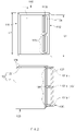
- FIG. 3 is a perspective view of a secondary battery according to a second embodiment of the present invention
- FIG. 4 is an exploded perspective view illustrating a state in which a portion of the secondary battery is removed according to the second embodiment of the present invention.
- a secondary battery 200 according to a second embodiment of the present invention relates to a secondary battery 200 comprising an electrolyte and a battery case 210.
- the battery case 210 comprises a main body 211 in which the , electrode assembly 120 and the electrolyte are accommodated, an additional electrolyte accommodation part 212 accommodating an additional electrolyte, a connection part 213 forming a moving passage 212d from the additional electrolyte accommodation part 212 to the main body 211, and an electrolyte impregnation member 230 provided in the connection part 213.
- the secondary battery 200 according to the second embodiment of the present invention may further comprise a sealing part 214.
- the secondary battery 200 according to the second embodiment of the present invention is the same as the secondary battery according to the first embodiment of the present invention except for a shape of the connection part 213.
- contents duplicated with the secondary battery according to the forgoing first embodiment of the present invention will be omitted or briefly described, and also, differences therebetween will be mainly described.
- the secondary battery 200 comprises the electrode assembly 120, the electrolyte, and the battery case 210 accommodating the electrode assembly 120 and the electrolyte.
- the battery case 210 may comprise the main body 211, the additional electrolyte accommodation part 212, the connection part 213, and the electrolyte impregnation member 230.
- An accommodation space 211a in which the electrode assembly 120 and the electrolyte are accommodated may be formed in the main body 211.
- a storage space 212a accommodating the additional electrolyte may be formed in the additional electrolyte accommodation part 212.
- the additional electrolyte accommodation part 212 may be formed in a rectangular cylindrical shape with a hollow therein.
- the additional electrolyte accommodation part 212 may have a length L1 that is same as a length L2 of the main body 211.
- connection part 213 may form the moving passage 213d through which the additional electrolyte is supplied from the additional electrolyte accommodation part 212 to the main body 211.
- connection part 213 may have the same thickness as each of the main body 211 and the additional electrolyte accommodation part 212.
- connection part 213 may connect upper and lower portions of the additional electrolyte accommodation part 212 to each other.
- connection part 213 may comprise a first connection part 213a connecting the main body 211 to the uppermost side of the additional electrolyte accommodation part 212 and a second connection part 113b connecting the main body 211 to the lowermost side of the additional electrolyte accommodation part 212.
- Each of the first connection part 213a and the second connection part 213b may be formed in a rectangular cylindrical shape.
- the electrolyte impregnation member 230 may be provided on the connection part 213 and may be impregnated with the additional electrolyte.
- the electrolyte impregnation member 230 may induce the additional electrolyte disposed in the additional electrolyte accommodation part 212 so as to be supplied to the accommodation space 211a of the main body 211.
- one side part 232 of the electrolyte impregnation member 230 may further extend into the storage space 212a of the additional electrolyte accommodation part 212.
- the electrolyte solution impregnation member 230 may comprise at least one or more of a nonwoven fabric, a separation membrane 124, or a cloth.
- the separation membrane used in the electrolyte impregnation member 230 may be made of the same material as the separator 224 used in the electrode assembly.
- the electrolyte impregnation member 230 may comprise an impregnation part 231 disposed on the connection part 213, one side part 232 that further extends into the storage space 212a of the additional electrolyte accommodation part 212, and the other side part 233 that further extends into the accommodation part of the main body 211.
- the other side part 233 of the electrolyte impregnation member 230 may have a size corresponding to a length and width of the accommodation space 211a of the additional electrolyte accommodation part 212.
- the other side part 233 of the electrolyte impregnation member 230 may be formed in a rectangular plate shape having a predetermined width.
- an end of the other side part 233 of the electrolyte impregnation member 230 may further extend into the accommodation space of the main body 211.
- the end of the other side part 233 of the electrolyte impregnation member 230 may extend between the electrode 122 and the separator 124.
- the electrolyte impregnation member 230 may be formed in a " ⁇ " shape.
- the impregnation part 231 may be formed to have a size corresponding to a length and width of the moving passage 213d of the connection part 213.
- the impregnation part 231 may comprise a first impregnation part 231a disposed on the first connection part 213a and connected to the uppermost side of the other side part 233 and a second impregnation part 232b disposed on the second connection part 213b and connected to the lowermost side of the other side part 233.
- the sealing part 214 may be formed between the main body 211 and the additional electrolyte accommodation part 212 except for the connection part 213.
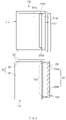
- FIG. 5 is a perspective view of a secondary battery according to a third embodiment of the present invention
- FIG. 6 is an exploded perspective view illustrating a state in which a portion of the secondary battery is removed according to the third embodiment of the present invention.
- a secondary battery 300 according to a third embodiment of the present invention relates to a secondary battery 300 comprising an electrolyte and a battery case 310.
- the battery case 310 comprises a main body 311 in which the , electrode assembly 120 and the electrolyte are accommodated, an additional electrolyte accommodation part 312 accommodating an additional electrolyte, a connection part 313 forming a moving passage 313d from the additional electrolyte accommodation part 312 to the main body 311, and an electrolyte impregnation member 330 provided in the connection part 313.
- the secondary battery 300 according to the third embodiment of the present invention may further comprise a sealing part 314.
- the secondary battery 400 according to the third embodiment of the present invention is the same as the secondary batteries according to the first and second embodiments of the present invention except for a shape of the connection part 313.
- contents duplicated with the secondary batteries according to the forgoing embodiments of the present invention will be omitted or briefly described, and also, differences therebetween will be mainly described.
- the secondary battery 300 comprises the electrode assembly 120, the electrolyte, and the battery case 310 accommodating the electrode assembly 120 and the electrolyte.
- the battery case 310 may comprise the main body 311, the additional electrolyte accommodation part 312, the connection part 313, and the electrolyte impregnation member 330.
- An accommodation space 311a in which the electrode assembly 120 and the electrolyte are accommodated may be formed in the main body 311.
- a storage space 312a accommodating the additional electrolyte may be formed in the additional electrolyte accommodation part 312.
- the additional electrolyte accommodation part 312 may be formed in a rectangular cylindrical shape with a hollow therein.
- the additional electrolyte accommodation part 312 may have the same length as the main body 311.
- connection part 313 may form the moving passage 313d through which the additional electrolyte is supplied from the additional electrolyte accommodation part 312 to the main body 311.
- connection part 313 may have the same thickness as each of the main body 311 and the additional electrolyte accommodation part 312.
- connection part 313 may connect a central portion of the additional electrolyte accommodation part 312 to each other.
- connection part 313 may comprise a third connection part 313c connecting the main body 311 to a central side of the additional electrolyte accommodation part 312.
- the third connection part 313c may be formed in a rectangular cylindrical shape.
- the electrolyte impregnation member 330 may be provided on the connection part 313 and may be impregnated with the additional electrolyte.
- the electrolyte impregnation member 330 may induce the additional electrolyte disposed in the additional electrolyte accommodation part 312 so as to be supplied to the accommodation space 311a of the main body 311.
- one side part 332 of the electrolyte impregnation member 330 may further extend into the storage space 312a of the additional electrolyte accommodation part 312.
- the electrolyte impregnation member 330 may comprise at least one or more of a nonwoven fabric, a separation membrane, or a cloth.
- the separation membrane used in the electrolyte impregnation member 330 may be made of the same material as the separator 224 used in the electrode assembly 120.
- the electrolyte impregnation member 330 may comprise an impregnation part 331 disposed on the connection part 313, one side part 332 that further extends into the storage space 312a of the additional electrolyte accommodation part 312, and the other side part 333 that further extends into the accommodation part main body 311.
- the other side part 333 of the electrolyte impregnation member 330 may have a size corresponding to a length and width of the accommodation space 311a of the additional electrolyte accommodation part 312.
- the other side part 333 of the electrolyte impregnation member 330 may be formed in a rectangular plate shape having a predetermined width.
- an end of the other side part 333 of the electrolyte impregnation member 330 may further extend into the accommodation space of the main body 311.
- the end of the other side part 333 of the electrolyte impregnation member 330 may extend between the electrode 122 and the separator 124.
- the electrolyte impregnation member 330 may be formed in a " " shape.
- the impregnation part 331 may be formed to have a size corresponding to a length and width of the moving passage 313d of the connection part 313.
- the impregnation part 331 may comprise a third impregnation part 331c disposed on the third connection part 313c and connected to a center side of the other side part 333.
- the sealing part 314 may be formed between the main body 311 and the additional electrolyte accommodation part 312 except for the connection part 313.
- the prepared negative electrode mixture slurry was applied on both surfaces of a copper collector, and then, dried and rolled to prepare a negative electrode.
- LiNi0.8Co0.1Mn0.1O2 as a positive electrode active material
- Denka black conductive agent
- PVdF binder
- the prepared positive electrode mixture slurry was applied on both surfaces of an aluminum collector, and then, dried and rolled to prepare a positive electrode.
- An electrode assembly in which the prepared positive electrode and negative electrode are stacked with a separator (poly propylene) therebetween was put into a battery case, and 2 wt% of fluoroethylene carbonate (FEC) was added to a solvent in which ethylene carbonate (EC) and ethyl methyl carbonate (EMC) are mixed at a volume of 3:7. Then, 4 ml of an electrolyte in which 1M of LiPF6 is dissolved was injected, and the battery case was sealed to manufacture the secondary battery.
- FEC fluoroethylene carbonate
- EMC ethyl methyl carbonate
- the secondary battery was manufactured in the same configuration as the secondary battery according to the first embodiment of the present invention, which is illustrated in FIG. 1 .
- a secondary battery comprising a main body accommodating the electrode assembly and the electrolyte, an additional electrolyte accommodation part having a storage space in which an additional electrolyte is accommodated, a connection part connecting a moving passage, through which the additional electrolyte is supplied from the additional electrolyte accommodation part to the main body, to the uppermost side, the lowermost side, and a central side, and an electrolyte impregnation member provided on the connection part and impregnated with the additional electrolyte.
- a sealing part was formed between the main body and the additional electrolyte accommodation part except for the connection part.
- the additional electrolyte was the same component as the electrolyte, and the electrolyte disposed in the additional electrolyte accommodation part was defined as the additional electrolyte.
- a secondary battery was manufactured in the same manner as in Manufacturing Example 1, except for a shape of a battery case, which is different from that of the battery case according to Manufacturing Example 1.
- the secondary battery was manufactured in the same configuration as the secondary battery according to the second embodiment of the present invention, which is illustrated in FIG. 3 .
- a secondary battery comprising a main body accommodating the electrode assembly and the electrolyte, an additional electrolyte accommodation part having a storage space in which an additional electrolyte is accommodated, a connection part connecting a moving passage, through which the additional electrolyte is supplied from the additional electrolyte accommodation part to the main body, to the uppermost side and the lowermost side, and an electrolyte impregnation member provided on the connection part and impregnated with the additional electrolyte.
- a sealing part was formed between the main body and the additional electrolyte accommodation part except for the connection part.
- a secondary battery was manufactured in the same manner as in Manufacturing Example 1, except for a shape of a battery case, which is different from that of the battery case according to Manufacturing Example 1.
- the secondary battery was manufactured in the same configuration as the secondary battery according to the third embodiment of the present invention, which is illustrated in FIG. 5 .
- a secondary battery comprising a main body accommodating the electrode assembly and the electrolyte, an additional electrolyte accommodation part having a storage space in which an additional electrolyte is accommodated, a connection part connecting a moving passage, through which the additional electrolyte is supplied from the additional electrolyte accommodation part to the main body, to a central side, and an electrolyte impregnation member provided on the connection part and impregnated with the additional electrolyte.
- a sealing part was formed between the main body and the additional electrolyte accommodation part except for the connection part.
- FIG. 7 is a perspective view of a secondary battery according to Comparative Example 1.
- a secondary battery was manufactured in the same manner as in Manufacturing Example 1, except that the additional electrolyte accommodation part, the connection part, and the sealing part are not formed in the battery case according to Manufacturing Example 1.
- a secondary battery 400 was manufactured by forming only a main body 411 accommodating an electrode assembly and an electrolyte in a battery case 410.
- FIG. 8 is a perspective view of a secondary battery according to Comparative Example 2.
- a secondary battery was manufactured in the same manner as in Manufacturing Example 1, except that the connection part and the sealing part are not formed in the battery case according to Manufacturing Example 1.
- a secondary battery 500 comprising a main body 511 accommodating an electrode assembly and an electrolyte and an additional electrolyte accommodation part 512 in a battery case 510 was manufactured.
- the main body 511 and the additional electrolyte accommodation part 512 were manufactured in a form in which an additional space is further formed in a side surface of the main body without being connected to each other by a connection part.
- the secondary batteries prepared in Manufacturing Examples 1 to 3 and Comparative Examples 1 and 2 were subjected to a charge/discharge reversibility test using an electrochemical charging/discharging device. During charging, current was applied to a voltage of 4.2 V (vs. Li/LI+) at a current density of 0.1 C-rate, and during discharging, the discharge was performed to a voltage of 2.5 V at the same current density.
- Table 1 shows a 300 cycle capacity retention rate compared to a first cycle discharge capacity.
- [Table 1] Manufactur ing Example 1 Manufacturi ng Example 2 Manufactur ing Example 3 Comparat ive Example 1 Comparat ive Example 2 300 cycle capacity retention rate (%) 76 74 73 43 62
Landscapes
- Chemical & Material Sciences (AREA)
- Chemical Kinetics & Catalysis (AREA)
- Electrochemistry (AREA)
- General Chemical & Material Sciences (AREA)
- Engineering & Computer Science (AREA)
- Manufacturing & Machinery (AREA)
- Secondary Cells (AREA)
Abstract
Description
- The present application claims the benefit of the priority of
Korean Patent Application No. 10-2020-0005637, filed on January 15, 2020 - The present invention relate to a secondary battery.
- Secondary batteries are rechargeable unlike primarily batteries, and also, the possibility of compact size and high capacity is high. Thus, recently, many studies on secondary batteries are being carried out. As technology development and demands for mobile devices increase, the demands for secondary batteries as energy sources are rapidly increasing.
- Rechargeable batteries are classified into coin type batteries, cylindrical type batteries, prismatic type batteries, and pouch type batteries according to a shape of a battery case. The secondary battery accommodates an electrode assembly and an electrolyte. In such a secondary battery, an electrode assembly mounted in a battery case is a chargeable and dischargeable power generating device having a structure in which an electrode and a separator are stacked.
- The electrode assembly may be approximately classified into a jelly-roll type electrode assembly in which a separator is interposed between a positive electrode and a negative electrode, each of which is provided as the form of a sheet coated with an active material, and then, the positive electrode, the separator, and the negative electrode are wound, a stacked type electrode assembly in which a plurality of positive and negative electrodes with a separator therebetween are sequentially stacked, and a stack/folding type electrode assembly in which stacked type unit cells are wound together with a separation film having a long length.
- Recently, the pouch-type battery in which a stack/folding type electrode assembly is built in a pouch-type battery case provided as an aluminum lamination sheet is attracting much attention due to its low manufacturing cost, small weight, easy shape deformation, and the like, and thus, its usage is gradually increasing.
- However, as the secondary battery is used, there has been a problem that an electrolyte is gradually consumed to deteriorate performance. The electrolyte may be gasified as the secondary battery is repeatedly charged and discharged and be gradually consumed by being accumulated in the form of a polymer.
- [Prior Art Document] (Patent Document)
Korean Patent Publication No. 10-2014-0015647 - One aspect of the present invention is to provide a secondary battery that is capable of easily supplying an additional electrolyte to the secondary battery.
- A secondary battery according to an embodiment of the present invention comprises a secondary battery, which comprises an electrode assembly, an electrolyte, and a battery case configured to accommodate the electrode assembly and the electrolyte, wherein the battery case comprises: a main body having accommodation space in which the electrode assembly and the electrolyte are accommodated; an additional electrolyte accommodation part having a storage space in which an additional electrolyte is accommodated; a connection part configured to form a moving passage through which the additional electrolyte is supplied from the addition electrolyte accommodation part to the main body; and an electrolyte impregnation member provided on the connection part and impregnated with the additional electrolyte.
- A battery pack according to an embodiment of the present invention comprises a battery pack comprising the secondary battery according to an embodiment of the present invention.
- According to the present invention, the additional electrolyte accommodation part in which the storage space for accommodating the additional electrolyte is formed may be provided in the secondary battery to easily supply the additional electrolyte and prevent the cycle performance from being deteriorated.
- In addition, the electrolyte impregnation member that is impregnated with the additional electrolyte may be provided on the connection part through which the additional electrolyte is supplied to the main body in which the electrolyte is accommodated from the addition electrolyte accommodation part to more smoothly supply the additional electrolyte, thereby more effectively improving the performance.
-
-
FIG. 1 is a perspective view of a secondary battery according to a first embodiment of the present invention. -
FIG. 2 is an exploded perspective view illustrating a state in which a portion of the secondary battery is removed according to the first embodiment of the present invention. -
FIG. 3 is a perspective view of a secondary battery according to a second embodiment of the present invention. -
FIG. 4 is an exploded perspective view illustrating a state in which a portion of the secondary battery is removed according to the second embodiment of the present invention. -
FIG. 5 is a perspective view of a secondary battery according to a third embodiment of the present invention. -
FIG. 6 is an exploded perspective view illustrating a state in which a portion of the secondary battery is removed according to the third embodiment of the present invention. -
FIG. 7 is a perspective view of a secondary battery according to Comparative Example 1. -
FIG. 8 is a perspective view of a secondary battery according to Comparative Example 2. - The objectives, specific advantages, and novel features of the present invention will become more apparent from the following detailed description taken in conjunction with the accompanying drawings. It should be noted that the reference numerals are added to the components of the drawings in the present specification with the same numerals as possible, even if they are illustrated in other drawings. Also, the present invention may be embodied in different forms and should not be construed as limited to the embodiments set forth herein. In the following description of the present invention, the detailed descriptions of related arts which may unnecessarily obscure the gist of the present invention will be omitted.
-
FIG. 1 is a perspective view of a secondary battery according to a first embodiment of the present invention, andFIG. 2 is an exploded perspective view illustrating a state in which a portion of the secondary battery is removed according to the first embodiment of the present invention. - Referring to
FIGS. 1 and2 , asecondary battery 100 according to a first embodiment of the present invention relates to asecondary battery 100 comprising an electrolyte and abattery case 110. Thebattery case 110 comprises amain body 111 in which theelectrode assembly 120 and the electrolyte are accommodated, an additionalelectrolyte accommodation part 112 accommodating an additional electrolyte, aconnection part 113 forming a movingpassage 113d from the additionalelectrolyte accommodation part 112 to themain body 111, and anelectrolyte impregnation member 130 provided in theconnection part 113. In addition, thesecondary battery 100 according to the first embodiment of the present invention may further comprise a sealingpart 114. - In more detail, the
secondary battery 100 according to the first embodiment of the present invention comprises theelectrode assembly 120, the electrolyte, and thebattery case 110 accommodating theelectrode assembly 120 and the electrolyte. - The
electrode assembly 120 may be a chargeable and dischargeable power generation element and may compriseelectrodes 122 andseparators 124, which are alternately stacked. - The
electrodes 122 may comprise apositive electrode 121 and anegative electrode 122. Here, theelectrode assembly 120 may have a structure in which thepositive electrode 121/theseparator 124/thenegative electrode 122 are alternately laminated. Also, the electrode lead 30 may comprise a positive electrode lead connected to thepositive electrode 121 and a negative electrode lead connected to thenegative electrode 122. - The
positive electrode 121 may comprise a positive electrode collector and a positive electrode active material stacked on the positive electrode collector. - The positive electrode collector may be made of an aluminum foil.
- The positive electrode active material may comprise lithium manganese oxide, lithium cobalt oxide, lithium nickel oxide, lithium iron phosphate, or a compound or mixture containing at least one of the above-described materials.
- The
negative electrode 122 may comprise a negative electrode collector and a negative electrode active material stacked on the negative electrode collector. - The negative electrode collector may be made of, for example, a foil made of a copper (Cu) material.
- The negative active material may be a compound or a mixture containing a graphite-based material.
- The
separator 124 is made of an insulation material to electrically insulate thepositive electrode 121 from thenegative electrode 122. Here, theseparator 124 may be made of a polyolefin-based resin film such as polyethylene or polypropylene having micropores. - The
battery case 110 may comprise themain body 111, the additionalelectrolyte accommodation part 112, theconnection part 113, and theelectrolyte impregnation member 130. - An
accommodation space 111a in which theelectrode assembly 120 and the electrolyte are accommodated may be formed in themain body 111. - A
storage space 112a accommodating the additional electrolyte may be formed in the additionalelectrolyte accommodation part 112. Here, the additional electrolyte may be the same component as the electrolyte contained in theaccommodation space 111a of themain body 111. - Also, the additional
electrolyte accommodation part 112 may have the same length as themain body 111. - Furthermore, the additional
electrolyte accommodation part 112 may be formed in a rectangular cylindrical shape with a hollow therein. - The
connection part 113 may form the movingpassage 113d through which the additional electrolyte is supplied from the additionalelectrolyte accommodation part 112 to themain body 111. - Also, the
connection part 113 may have the same thickness as each of themain body 111 and the additionalelectrolyte accommodation part 112. - Furthermore, the
connection part 113 may connect upper, lower and central portions of the additionalelectrolyte accommodation part 112 to each other. - Here, the
connection part 113 may comprise afirst connection part 113a connecting themain body 111 to the uppermost side of the additionalelectrolyte accommodation part 112, asecond connection part 113b connecting themain body 111 to the lowermost side of the additionalelectrolyte accommodation part 112, and athird connection part 113c connecting the main body to a central side of the additionalelectrolyte accommodation part 112. - Here, each of the
first connection part 113a, thesecond connection part 113b, and thethird connection part 113c may be formed in a rectangular cylindrical shape. - The
electrolyte impregnation member 130 may be provided on theconnection part 113 and may be impregnated with the additional electrolyte. - Thus, when an amount of electrolyte accommodated in the
accommodation space 111a of themain body 111 is reduced, theelectrolyte impregnation member 130 may induce the additional electrolyte disposed in the additionalelectrolyte accommodation part 112 so as to be supplied to theaccommodation space 111a of themain body 111. - Also, one
side part 132 of theelectrolyte impregnation member 130 may further extend into thestorage space 112a of the additionalelectrolyte accommodation part 112. - Also, the
electrolyte impregnation member 130 may comprise at least one or more of a nonwoven fabric, a separation membrane, or a cloth. Here, the separation membrane used in theelectrolyte impregnation member 130 may be made of the same material as theseparator 124 used in theelectrode assembly 120. - The
electrolyte impregnation member 130 may comprise animpregnation part 131 disposed on the connection part, oneside part 132 that further extends into thestorage space 112a of the additionalelectrolyte accommodation part 112, and theother side part 133 of which an end further extends into the accommodation part of themain body 111. - Here, the
other side part 133 of theelectrolyte impregnation member 130 may have a size corresponding to a length and width of theaccommodation space 111a of the additionalelectrolyte accommodation part 112. Here, theother side part 133 of theelectrolyte impregnation member 130 may be formed in a rectangular plate shape having a predetermined width. - Furthermore, an end of the
other side part 133 of theelectrolyte impregnation member 130 may further extend into the accommodation space of themain body 111. Here, the end of theother side part 133 of theelectrolyte impregnation member 130 may extend between theelectrode 122 and theseparator 124. - Also, the
electrolyte impregnation member 130 may be formed in an "E" shape. - The
impregnation part 131 may be formed to have a size corresponding to a length and width of the movingpassage 113d of theconnection part 113. - Also, the
impregnation part 131 may comprise afirst impregnation part 131a disposed on thefirst connection part 113a and connected to the uppermost side of theother side part 133, a second impregnation part 132b disposed on thesecond connection part 113b and connected to the lowermost side of theother side part 133, and a third impregnation part 133c disposed on thethird connection part 113c and connected to a central side of theother side part 133. - The sealing
part 114 may be formed between themain body 111 and the additionalelectrolyte accommodation part 112 except for theconnection part 113. - Also, the sealing
part 114 may comprise afirst sealing part 114a and asecond sealing part 114b. Thefirst sealing part 114a may be provided between thefirst connection part 113a connecting the uppermost side and thethird connection part 113c connecting the central side, and thesecond sealing part 114b may be provided between thesecond connection part 113b connecting the lowermost side and thethird connection part 113c connecting the central side. - Furthermore, the sealing
part 114 may be formed by thermally fusing thebattery case 110. - The plurality of
secondary batteries 100 according to the first embodiment of the present invention may be electrically connected to each other to form a battery pack. - Hereinafter, a secondary battery according to a second embodiment of the present invention will be described.
-
FIG. 3 is a perspective view of a secondary battery according to a second embodiment of the present invention, andFIG. 4 is an exploded perspective view illustrating a state in which a portion of the secondary battery is removed according to the second embodiment of the present invention. - Referring to
FIGS. 3 and4 , asecondary battery 200 according to a second embodiment of the present invention relates to asecondary battery 200 comprising an electrolyte and abattery case 210. Thebattery case 210 comprises amain body 211 in which the ,electrode assembly 120 and the electrolyte are accommodated, an additionalelectrolyte accommodation part 212 accommodating an additional electrolyte, aconnection part 213 forming a movingpassage 212d from the additionalelectrolyte accommodation part 212 to themain body 211, and anelectrolyte impregnation member 230 provided in theconnection part 213. In addition, thesecondary battery 200 according to the second embodiment of the present invention may further comprise a sealingpart 214. - The
secondary battery 200 according to the second embodiment of the present invention is the same as the secondary battery according to the first embodiment of the present invention except for a shape of theconnection part 213. Thus, in the second embodiment of thesecondary battery 200, contents duplicated with the secondary battery according to the forgoing first embodiment of the present invention will be omitted or briefly described, and also, differences therebetween will be mainly described. - In more detail, the
secondary battery 200 comprises theelectrode assembly 120, the electrolyte, and thebattery case 210 accommodating theelectrode assembly 120 and the electrolyte. - The
battery case 210 may comprise themain body 211, the additionalelectrolyte accommodation part 212, theconnection part 213, and theelectrolyte impregnation member 230. - An
accommodation space 211a in which theelectrode assembly 120 and the electrolyte are accommodated may be formed in themain body 211. - A
storage space 212a accommodating the additional electrolyte may be formed in the additionalelectrolyte accommodation part 212. Here, the additionalelectrolyte accommodation part 212 may be formed in a rectangular cylindrical shape with a hollow therein. - Also, the additional
electrolyte accommodation part 212 may have a length L1 that is same as a length L2 of themain body 211. - The
connection part 213 may form the moving passage 213d through which the additional electrolyte is supplied from the additionalelectrolyte accommodation part 212 to themain body 211. - The
connection part 213 may have the same thickness as each of themain body 211 and the additionalelectrolyte accommodation part 212. - The
connection part 213 may connect upper and lower portions of the additionalelectrolyte accommodation part 212 to each other. - The
connection part 213 may comprise afirst connection part 213a connecting themain body 211 to the uppermost side of the additionalelectrolyte accommodation part 212 and asecond connection part 113b connecting themain body 211 to the lowermost side of the additionalelectrolyte accommodation part 212. - Each of the
first connection part 213a and thesecond connection part 213b may be formed in a rectangular cylindrical shape. - The
electrolyte impregnation member 230 may be provided on theconnection part 213 and may be impregnated with the additional electrolyte. - Thus, when an amount of electrolyte accommodated in the
accommodation space 211a of themain body 211 is reduced, theelectrolyte impregnation member 230 may induce the additional electrolyte disposed in the additionalelectrolyte accommodation part 212 so as to be supplied to theaccommodation space 211a of themain body 211. - Also, one
side part 232 of theelectrolyte impregnation member 230 may further extend into thestorage space 212a of the additionalelectrolyte accommodation part 212. - Also, the electrolyte
solution impregnation member 230 may comprise at least one or more of a nonwoven fabric, aseparation membrane 124, or a cloth. Here, the separation membrane used in theelectrolyte impregnation member 230 may be made of the same material as the separator 224 used in the electrode assembly. - Also, the
electrolyte impregnation member 230 may comprise animpregnation part 231 disposed on theconnection part 213, oneside part 232 that further extends into thestorage space 212a of the additionalelectrolyte accommodation part 212, and theother side part 233 that further extends into the accommodation part of themain body 211. - Here, the
other side part 233 of theelectrolyte impregnation member 230 may have a size corresponding to a length and width of theaccommodation space 211a of the additionalelectrolyte accommodation part 212. Here, theother side part 233 of theelectrolyte impregnation member 230 may be formed in a rectangular plate shape having a predetermined width. - Furthermore, an end of the
other side part 233 of theelectrolyte impregnation member 230 may further extend into the accommodation space of themain body 211. Here, the end of theother side part 233 of theelectrolyte impregnation member 230 may extend between theelectrode 122 and theseparator 124. - Also, the
electrolyte impregnation member 230 may be formed in a "⊏" shape. - The
impregnation part 231 may be formed to have a size corresponding to a length and width of the moving passage 213d of theconnection part 213. - Also, the
impregnation part 231 may comprise afirst impregnation part 231a disposed on thefirst connection part 213a and connected to the uppermost side of theother side part 233 and a second impregnation part 232b disposed on thesecond connection part 213b and connected to the lowermost side of theother side part 233. - The sealing
part 214 may be formed between themain body 211 and the additionalelectrolyte accommodation part 212 except for theconnection part 213. - Hereinafter, a secondary battery according to a third embodiment of the present invention will be described.
-
FIG. 5 is a perspective view of a secondary battery according to a third embodiment of the present invention, andFIG. 6 is an exploded perspective view illustrating a state in which a portion of the secondary battery is removed according to the third embodiment of the present invention. - Referring to
FIGS. 5 and6 , asecondary battery 300 according to a third embodiment of the present invention relates to asecondary battery 300 comprising an electrolyte and abattery case 310. Thebattery case 310 comprises amain body 311 in which the ,electrode assembly 120 and the electrolyte are accommodated, an additionalelectrolyte accommodation part 312 accommodating an additional electrolyte, aconnection part 313 forming a moving passage 313d from the additionalelectrolyte accommodation part 312 to themain body 311, and anelectrolyte impregnation member 330 provided in theconnection part 313. In addition, thesecondary battery 300 according to the third embodiment of the present invention may further comprise a sealingpart 314. - The
secondary battery 400 according to the third embodiment of the present invention is the same as the secondary batteries according to the first and second embodiments of the present invention except for a shape of theconnection part 313. Thus, in the third embodiment of thesecondary battery 300, contents duplicated with the secondary batteries according to the forgoing embodiments of the present invention will be omitted or briefly described, and also, differences therebetween will be mainly described. - In more detail, the
secondary battery 300 comprises theelectrode assembly 120, the electrolyte, and thebattery case 310 accommodating theelectrode assembly 120 and the electrolyte. - The
battery case 310 may comprise themain body 311, the additionalelectrolyte accommodation part 312, theconnection part 313, and theelectrolyte impregnation member 330. - An
accommodation space 311a in which theelectrode assembly 120 and the electrolyte are accommodated may be formed in themain body 311. - A
storage space 312a accommodating the additional electrolyte may be formed in the additionalelectrolyte accommodation part 312. Here, the additionalelectrolyte accommodation part 312 may be formed in a rectangular cylindrical shape with a hollow therein. - The additional
electrolyte accommodation part 312 may have the same length as themain body 311. - The
connection part 313 may form the moving passage 313d through which the additional electrolyte is supplied from the additionalelectrolyte accommodation part 312 to themain body 311. - Also, the
connection part 313 may have the same thickness as each of themain body 311 and the additionalelectrolyte accommodation part 312. - Furthermore, the
connection part 313 may connect a central portion of the additionalelectrolyte accommodation part 312 to each other. - Here, the
connection part 313 may comprise athird connection part 313c connecting themain body 311 to a central side of the additionalelectrolyte accommodation part 312. - Here, the
third connection part 313c may be formed in a rectangular cylindrical shape. - The
electrolyte impregnation member 330 may be provided on theconnection part 313 and may be impregnated with the additional electrolyte. - Thus, when an amount of electrolyte accommodated in the
accommodation space 311a of themain body 311 is reduced, theelectrolyte impregnation member 330 may induce the additional electrolyte disposed in the additionalelectrolyte accommodation part 312 so as to be supplied to theaccommodation space 311a of themain body 311. - Also, one
side part 332 of theelectrolyte impregnation member 330 may further extend into thestorage space 312a of the additionalelectrolyte accommodation part 312. - Also, the
electrolyte impregnation member 330 may comprise at least one or more of a nonwoven fabric, a separation membrane, or a cloth. Here, the separation membrane used in theelectrolyte impregnation member 330 may be made of the same material as the separator 224 used in theelectrode assembly 120. - The
electrolyte impregnation member 330 may comprise animpregnation part 331 disposed on theconnection part 313, oneside part 332 that further extends into thestorage space 312a of the additionalelectrolyte accommodation part 312, and theother side part 333 that further extends into the accommodation partmain body 311. - Here, the
other side part 333 of theelectrolyte impregnation member 330 may have a size corresponding to a length and width of theaccommodation space 311a of the additionalelectrolyte accommodation part 312. Here, theother side part 333 of theelectrolyte impregnation member 330 may be formed in a rectangular plate shape having a predetermined width. - Furthermore, an end of the
other side part 333 of theelectrolyte impregnation member 330 may further extend into the accommodation space of themain body 311. Here, the end of theother side part 333 of theelectrolyte impregnation member 330 may extend between theelectrode 122 and theseparator 124. - Also, the
electrolyte impregnation member 330 may be formed in a "" shape.
- The
impregnation part 331 may be formed to have a size corresponding to a length and width of the moving passage 313d of theconnection part 313. - Also, the
impregnation part 331 may comprise athird impregnation part 331c disposed on thethird connection part 313c and connected to a center side of theother side part 333. - The sealing
part 314 may be formed between themain body 311 and the additionalelectrolyte accommodation part 312 except for theconnection part 313. - 92% by weight of a negative electrode active material (graphite:Sio=7:3), 3% by weight of Denka black (conductive agent), 3.5% by weight of SBR (binder), and 1.5% by weight of CMC (thickening agent) were added to water to prepare negative electrode mixture slurry.
- The prepared negative electrode mixture slurry was applied on both surfaces of a copper collector, and then, dried and rolled to prepare a negative electrode.
- 97.5% by weight of LiNi0.8Co0.1Mn0.1O2 as a positive electrode active material, 1% by weight of Denka black (conductive agent), and 1.5% by weight of PVdF (binder) were added to NMP to prepare positive electrode mixture slurry.
- The prepared positive electrode mixture slurry was applied on both surfaces of an aluminum collector, and then, dried and rolled to prepare a positive electrode.
- An electrode assembly in which the prepared positive electrode and negative electrode are stacked with a separator (poly propylene) therebetween was put into a battery case, and 2 wt% of fluoroethylene carbonate (FEC) was added to a solvent in which ethylene carbonate (EC) and ethyl methyl carbonate (EMC) are mixed at a volume of 3:7. Then, 4 ml of an electrolyte in which 1M of LiPF6 is dissolved was injected, and the battery case was sealed to manufacture the secondary battery.
- Here, the secondary battery was manufactured in the same configuration as the secondary battery according to the first embodiment of the present invention, which is illustrated in
FIG. 1 . - That is, a secondary battery comprising a main body accommodating the electrode assembly and the electrolyte, an additional electrolyte accommodation part having a storage space in which an additional electrolyte is accommodated, a connection part connecting a moving passage, through which the additional electrolyte is supplied from the additional electrolyte accommodation part to the main body, to the uppermost side, the lowermost side, and a central side, and an electrolyte impregnation member provided on the connection part and impregnated with the additional electrolyte. At this time, a sealing part was formed between the main body and the additional electrolyte accommodation part except for the connection part. Here, the additional electrolyte was the same component as the electrolyte, and the electrolyte disposed in the additional electrolyte accommodation part was defined as the additional electrolyte.
- In Manufacturing Example 2, a secondary battery was manufactured in the same manner as in Manufacturing Example 1, except for a shape of a battery case, which is different from that of the battery case according to Manufacturing Example 1.
- Here, the secondary battery was manufactured in the same configuration as the secondary battery according to the second embodiment of the present invention, which is illustrated in
FIG. 3 . - That is, a secondary battery comprising a main body accommodating the electrode assembly and the electrolyte, an additional electrolyte accommodation part having a storage space in which an additional electrolyte is accommodated, a connection part connecting a moving passage, through which the additional electrolyte is supplied from the additional electrolyte accommodation part to the main body, to the uppermost side and the lowermost side, and an electrolyte impregnation member provided on the connection part and impregnated with the additional electrolyte. At this time, a sealing part was formed between the main body and the additional electrolyte accommodation part except for the connection part.
- In Manufacturing Example 3, a secondary battery was manufactured in the same manner as in Manufacturing Example 1, except for a shape of a battery case, which is different from that of the battery case according to Manufacturing Example 1.
- Here, the secondary battery was manufactured in the same configuration as the secondary battery according to the third embodiment of the present invention, which is illustrated in
FIG. 5 . - That is, a secondary battery comprising a main body accommodating the electrode assembly and the electrolyte, an additional electrolyte accommodation part having a storage space in which an additional electrolyte is accommodated, a connection part connecting a moving passage, through which the additional electrolyte is supplied from the additional electrolyte accommodation part to the main body, to a central side, and an electrolyte impregnation member provided on the connection part and impregnated with the additional electrolyte. At this time, a sealing part was formed between the main body and the additional electrolyte accommodation part except for the connection part.
-
FIG. 7 is a perspective view of a secondary battery according to Comparative Example 1. - Referring to
FIG. 7 , in Comparative Example 1, a secondary battery was manufactured in the same manner as in Manufacturing Example 1, except that the additional electrolyte accommodation part, the connection part, and the sealing part are not formed in the battery case according to Manufacturing Example 1. - That is, a
secondary battery 400 was manufactured by forming only amain body 411 accommodating an electrode assembly and an electrolyte in abattery case 410. -
FIG. 8 is a perspective view of a secondary battery according to Comparative Example 2. - Referring to
FIG. 8 , in Comparative Example 2, a secondary battery was manufactured in the same manner as in Manufacturing Example 1, except that the connection part and the sealing part are not formed in the battery case according to Manufacturing Example 1. - That is, a
secondary battery 500 comprising amain body 511 accommodating an electrode assembly and an electrolyte and an additionalelectrolyte accommodation part 512 in abattery case 510 was manufactured. Here, themain body 511 and the additionalelectrolyte accommodation part 512 were manufactured in a form in which an additional space is further formed in a side surface of the main body without being connected to each other by a connection part. - The secondary batteries prepared in Manufacturing Examples 1 to 3 and Comparative Examples 1 and 2 were subjected to a charge/discharge reversibility test using an electrochemical charging/discharging device. During charging, current was applied to a voltage of 4.2 V (vs. Li/LI+) at a current density of 0.1 C-rate, and during discharging, the discharge was performed to a voltage of 2.5 V at the same current density. Table 1 shows a 300 cycle capacity retention rate compared to a first cycle discharge capacity.
[Table 1] Manufactur ing Example 1 Manufacturi ng Example 2 Manufactur ing Example 3 Comparat ive Example 1 Comparat ive Example 2 300 cycle capacity retention rate (%) 76 74 73 43 62 - Referring to Table 1, in the case of Manufacturing Examples 1 to 3, since there is a surplus electrolyte in the additional electrolyte space, cycle deterioration due to depletion of the electrolyte is not severe, and thus, the 300 cycle capacity retention rate was high. On the other hand, in the case of Comparative Example 1, which relates to the general secondary battery structure, it is seen that since there is no surplus electrolyte, the 300 cycle capacity retention rate decreases by about 20% to about 23% due to the depletion of the electrolyte. In the case of Comparative Example 2, it is seen that although the additional electrolyte space is formed, and the surplus electrolyte is put in the additional electrolyte space, the connection part in which the electrolyte impregnation member is disposed is not provided between the electrode part and the additional electrolyte space, and thus, the electrolyte is not induced, and also, the sealing part is not provided to deteriorate electrode compression force due to the battery case, and thus, the charging/discharging of the electrode is not performed well during the charging/discharging, and as a result, the 300 cycle capacity retention rate decreases by about 11% to about 40%. As a result, it is seen that since the capacity retention rate in Manufacturing Examples 1 to 3 is significantly higher than that in Comparative Examples 1 and 2, the battery capacity has been improved.
- While the present invention has been particularly shown and described with reference to exemplary embodiments thereof, it is to be understood that the scope of the present invention is not limited to the secondary battery according to the present invention. It will be understood by those of ordinary skill in the art that various changes in form and details may be made therein without departing from the spirit and scope of the present invention.
- Furthermore, the scope of protection of the present invention will be clarified by the appended claims.
-
- 100: Secondary battery
- 110, 210, 310: Battery case
- 111, 211, 311: Main body
- 111a: Accommodation space
- 112, 212, 312: Additional electrolyte accommodation part
- 112a: Storage space
- 113, 213, 313: Connection part
- 113a, 213a: First connection part
- 113b, 312b: Second connection part
- 113c, 213c: Third connection part
- 114, 214, 314: Sealing part
- 114a: First sealing part
- 114b: Second sealing part
- 120: Electrode assembly
- 121: Positive electrode
- 122: Negative electrode
- 123: Electrode
- 124: Separator
- 130, 230, 330: Electrolyte impregnation member
- 131, 231, 331: Impregnation part
- 132, 232, 332: One side part
- 133, 233, 333: The other side part
Claims (15)
- A secondary battery, which comprises an electrode assembly, an electrolyte, and a battery case configured to accommodate the electrode assembly and the electrolyte,
wherein the battery case comprises:a main body having accommodation space in which the electrode assembly and the electrolyte are accommodated;an additional electrolyte accommodation part having a storage space in which an additional electrolyte is accommodated;a connection part configured to form a moving passage through which the additional electrolyte is supplied from the addition electrolyte accommodation part to the main body; andan electrolyte impregnation member provided on the connection part and impregnated with the additional electrolyte. - The secondary battery of claim 1, wherein the electrolyte impregnation member induces the additional electrolyte, which is disposed in the additional electrolyte accommodation part, to be supplied into the accommodation space of the main body when an amount of electrolyte accommodated in the accommodation space of the main body decreases.
- The secondary battery of claim 1, wherein one side part of the electrolyte impregnation member further extends into the storage space of the additional electrolyte accommodation part.
- The secondary battery of claim 1, wherein an end of the other side part of the electrolyte impregnation member further extends into the accommodation space of the main body.
- The secondary battery of claim 4, wherein the electrode assembly comprises electrodes and a separator, which are alternately stacked, and
the end of the other side part of the electrolyte impregnation member extends between the electrodes and the separator. - The secondary battery of claim 1, wherein the electrolyte impregnation member comprises at least one or more of a nonwoven fabric, a separation membrane, or a cloth.
- The secondary battery of claim 1, wherein the connection part connects the main body to upper and lower portions or a central portion of the additional electrolyte accommodation part.
- The secondary battery of claim 1, wherein the connection part connects the main body to upper and lower portions and a central portion of the additional electrolyte accommodation part.
- The secondary battery of claim 8, wherein the connection part comprises:a first connection part configured to connect the main body to the uppermost side of the additional electrolyte accommodation part;a second connection part configured to connect the main body to the lowermost side of the additional electrolyte accommodation part; anda third connection part configured to connect the main body to a central side of the additional electrolyte accommodation part.
- The secondary battery of claim 9, wherein the electrolyte impregnation member comprises:an impregnation part disposed on the connection part;one side part that further extends into the storage space of the additional electrolyte accommodation part; andthe other side part that further extends into the accommodation space of the main body,wherein the other side part has a size corresponding to a length and width of the accommodation space of the additional electrolyte accommodation part, andthe impregnation part has a size corresponding to a length and width of the moving passage of the connection part.
- The secondary battery of claim 10, wherein the other side part has a rectangular plate shape having a predetermined width, and
the impregnation part comprises:a first impregnation part disposed on the first connection part and connected to the uppermost side of the other side part;a second impregnation part disposed on the second connection part and connected to the lowermost side of the other side part; anda third impregnation part disposed on the third connection part and connected to the central side of the other side part. - The secondary battery of claim 1, wherein the additional electrolyte accommodation part has the same length as the main body.
- The secondary battery of claim 1, further comprising a sealing part between the main body and the additional electrolyte accommodation part except for the connection part.
- The secondary battery of claim 1, wherein the connection part has the same thickness as each of the main body and the additional electrolyte accommodation part.
- A battery pack comprising the secondary battery of any one of claims 1 to 14.
Applications Claiming Priority (2)
| Application Number | Priority Date | Filing Date | Title |
|---|---|---|---|
| KR1020200005637A KR102825293B1 (en) | 2020-01-15 | 2020-01-15 | Rechargeable battery |
| PCT/KR2021/000345 WO2021145623A1 (en) | 2020-01-15 | 2021-01-11 | Secondary battery |
Publications (2)
| Publication Number | Publication Date |
|---|---|
| EP4060803A1 true EP4060803A1 (en) | 2022-09-21 |
| EP4060803A4 EP4060803A4 (en) | 2024-07-31 |
Family
ID=76864309
Family Applications (1)
| Application Number | Title | Priority Date | Filing Date |
|---|---|---|---|
| EP21740682.6A Pending EP4060803A4 (en) | 2020-01-15 | 2021-01-11 | SECONDARY BATTERY |
Country Status (6)
| Country | Link |
|---|---|
| US (1) | US20230013715A1 (en) |
| EP (1) | EP4060803A4 (en) |
| JP (1) | JP7427316B2 (en) |
| KR (1) | KR102825293B1 (en) |
| CN (1) | CN114902488B (en) |
| WO (1) | WO2021145623A1 (en) |
Family Cites Families (17)
| Publication number | Priority date | Publication date | Assignee | Title |
|---|---|---|---|---|
| JP3175928B2 (en) | 1999-03-17 | 2001-06-11 | 日本電気株式会社 | Rechargeable battery |
| JP2001351671A (en) | 2000-06-09 | 2001-12-21 | Furukawa Battery Co Ltd:The | Lead storage battery |
| JP4994603B2 (en) * | 2005-04-21 | 2012-08-08 | 三菱電機株式会社 | Electric double layer capacitor |
| JP2008159315A (en) | 2006-12-21 | 2008-07-10 | Fdk Corp | Lithium ion storage / release type organic electrolyte storage battery |
| JP5626872B2 (en) * | 2010-09-16 | 2014-11-19 | 学校法人同志社 | Hydrogen / air secondary battery |
| JP5397436B2 (en) * | 2010-11-18 | 2014-01-22 | 日産自動車株式会社 | Secondary battery |
| KR101651515B1 (en) * | 2011-10-10 | 2016-08-29 | 주식회사 엘지화학 | Secondary battery with automatic electrolyte supplementing function |
| TWI437751B (en) * | 2011-12-09 | 2014-05-11 | Lorom Ind Co Ltd | Can automatically add the electrolyte lithium battery core |
| JP6102062B2 (en) | 2012-02-28 | 2017-03-29 | 株式会社Gsユアサ | Electricity storage element |
| KR101528001B1 (en) | 2012-06-22 | 2015-06-10 | 주식회사 엘지화학 | Electrode assembly, manufacture thereof, and secondary batteries including same |
| US9735402B2 (en) * | 2013-07-30 | 2017-08-15 | Lg Chem, Ltd. | Battery cell having double sealing structure |
| KR20150014637A (en) * | 2013-07-30 | 2015-02-09 | 주식회사 엘지화학 | Secondary Battery Capable of Additional Supplying of Electrolyte |
| KR101732697B1 (en) * | 2014-09-16 | 2017-05-04 | 에스케이이노베이션 주식회사 | Lithium secondary battery |
| KR102297666B1 (en) * | 2014-10-24 | 2021-09-02 | 에스케이이노베이션 주식회사 | Secondary battery and manufacturing method thereof |
| KR102232542B1 (en) * | 2017-01-11 | 2021-03-26 | 주식회사 엘지화학 | Battery Cell Having Double Sealing Portion of Structure Capable of Additionally Supplying Electrolyte |
| WO2018212121A1 (en) * | 2017-05-18 | 2018-11-22 | 株式会社村田製作所 | Battery semi-fabricated product, battery, battery manufacturing method, battery pack, electronic device, vehicle, power tool, and power storage system |
| CN109860444A (en) * | 2018-12-19 | 2019-06-07 | 惠州亿纬锂能股份有限公司 | A kind of battery packaging structure and method |
-
2020
- 2020-01-15 KR KR1020200005637A patent/KR102825293B1/en active Active
-
2021
- 2021-01-11 CN CN202180007942.0A patent/CN114902488B/en active Active
- 2021-01-11 JP JP2022538856A patent/JP7427316B2/en active Active
- 2021-01-11 US US17/785,289 patent/US20230013715A1/en active Pending
- 2021-01-11 WO PCT/KR2021/000345 patent/WO2021145623A1/en not_active Ceased
- 2021-01-11 EP EP21740682.6A patent/EP4060803A4/en active Pending
Also Published As
| Publication number | Publication date |
|---|---|
| KR20210092093A (en) | 2021-07-23 |
| JP7427316B2 (en) | 2024-02-05 |
| EP4060803A4 (en) | 2024-07-31 |
| WO2021145623A1 (en) | 2021-07-22 |
| CN114902488B (en) | 2025-12-02 |
| CN114902488A (en) | 2022-08-12 |
| KR102825293B1 (en) | 2025-06-26 |
| JP2023508372A (en) | 2023-03-02 |
| US20230013715A1 (en) | 2023-01-19 |
Similar Documents
| Publication | Publication Date | Title |
|---|---|---|
| US8067112B2 (en) | Stacked lithium secondary battery and its fabrication utilizing a folded configuration | |
| EP4270565A1 (en) | Electrode assembly and secondary battery comprising same | |
| KR20140064418A (en) | Secondary battery module | |
| US11296325B2 (en) | Electrode for secondary battery including electrode protecting layer | |
| EP3598556A1 (en) | Electrode and electrode assembly | |
| US20060240290A1 (en) | High rate pulsed battery | |
| EP4037068A1 (en) | Electrode assembly and secondary battery comprising same | |
| WO2004097971A1 (en) | Stacked lithium secondary battery and its fabrication | |
| KR102943877B1 (en) | Lithium rechargeable battery and lithium rechargeable battery manufacturing method | |
| KR20190082180A (en) | Secondary Battery Module | |
| US11322799B2 (en) | Electrode including single-sided electrode with inorganic coating layer attached to slurry on collector and electrode assembly including the same | |
| EP4060803A1 (en) | Secondary battery | |
| KR101416805B1 (en) | Folding cell and super capacitor folding type having the same | |
| US11069899B2 (en) | Negative electrode for secondary battery | |
| KR102795173B1 (en) | Electrode plate for lithium secondary battery and method of manufacturing the same | |
| EP4164028A1 (en) | Electrode assembly and secondary battery comprising same | |
| US20250055018A1 (en) | Electrode Assembly and Battery Cell Including the Same | |
| KR101416806B1 (en) | Folding cell and super capacitor folding type having the same | |
| US20260045641A1 (en) | Battery cell, battery, and electric apparatus | |
| CN118435416A (en) | Electrode assembly and battery cell including the electrode assembly | |
| JP2012129039A (en) | Nonaqueous electrolytic solution secondary battery | |
| JP2019169651A (en) | Lithium ion capacitor | |
| JPWO1997036337A1 (en) | Lithium secondary batteries, chargers, and information terminal equipment | |
| JP2000228192A (en) | Non-aqueous electrolyte battery |
Legal Events
| Date | Code | Title | Description |
|---|---|---|---|
| STAA | Information on the status of an ep patent application or granted ep patent |
Free format text: STATUS: THE INTERNATIONAL PUBLICATION HAS BEEN MADE |
|
| PUAI | Public reference made under article 153(3) epc to a published international application that has entered the european phase |
Free format text: ORIGINAL CODE: 0009012 |
|
| STAA | Information on the status of an ep patent application or granted ep patent |
Free format text: STATUS: REQUEST FOR EXAMINATION WAS MADE |
|
| 17P | Request for examination filed |
Effective date: 20220615 |
|
| AK | Designated contracting states |
Kind code of ref document: A1 Designated state(s): AL AT BE BG CH CY CZ DE DK EE ES FI FR GB GR HR HU IE IS IT LI LT LU LV MC MK MT NL NO PL PT RO RS SE SI SK SM TR |
|
| DAV | Request for validation of the european patent (deleted) | ||
| DAX | Request for extension of the european patent (deleted) | ||
| A4 | Supplementary search report drawn up and despatched |
Effective date: 20240703 |
|
| RIC1 | Information provided on ipc code assigned before grant |
Ipc: H01M 50/682 20210101ALI20240627BHEP Ipc: H01M 10/42 20060101ALI20240627BHEP Ipc: H01M 50/10 20210101ALI20240627BHEP Ipc: H01M 50/103 20210101ALI20240627BHEP Ipc: H01M 10/058 20100101ALI20240627BHEP Ipc: H01M 50/60 20210101AFI20240627BHEP |
|
| STAA | Information on the status of an ep patent application or granted ep patent |
Free format text: STATUS: EXAMINATION IS IN PROGRESS |
|
| 17Q | First examination report despatched |
Effective date: 20250328 |
|
| GRAP | Despatch of communication of intention to grant a patent |
Free format text: ORIGINAL CODE: EPIDOSNIGR1 |
|
| STAA | Information on the status of an ep patent application or granted ep patent |
Free format text: STATUS: GRANT OF PATENT IS INTENDED |
|
| RIC1 | Information provided on ipc code assigned before grant |
Ipc: H01M 50/60 20210101AFI20250924BHEP Ipc: H01M 10/058 20100101ALI20250924BHEP Ipc: H01M 50/103 20210101ALI20250924BHEP Ipc: H01M 50/10 20210101ALI20250924BHEP Ipc: H01M 10/42 20060101ALI20250924BHEP Ipc: H01M 50/682 20210101ALI20250924BHEP Ipc: H01M 50/70 20210101ALI20250924BHEP Ipc: H01M 50/691 20210101ALI20250924BHEP Ipc: H01M 50/627 20210101ALI20250924BHEP Ipc: H01M 10/052 20100101ALI20250924BHEP Ipc: H01M 10/04 20060101ALI20250924BHEP |
|
| INTG | Intention to grant announced |
Effective date: 20251010 |
|
| P01 | Opt-out of the competence of the unified patent court (upc) registered |
Free format text: CASE NUMBER: UPC_APP_0012137_4060803/2025 Effective date: 20251105 |
|
| GRAS | Grant fee paid |
Free format text: ORIGINAL CODE: EPIDOSNIGR3 |
|
| GRAA | (expected) grant |
Free format text: ORIGINAL CODE: 0009210 |
|
| STAA | Information on the status of an ep patent application or granted ep patent |
Free format text: STATUS: THE PATENT HAS BEEN GRANTED |