EP4060773A1 - Separator for fuel cells, method for producing separator for fuel cells, and method for producing sheet for thermal transfer - Google Patents
Separator for fuel cells, method for producing separator for fuel cells, and method for producing sheet for thermal transfer Download PDFInfo
- Publication number
- EP4060773A1 EP4060773A1 EP20886202.9A EP20886202A EP4060773A1 EP 4060773 A1 EP4060773 A1 EP 4060773A1 EP 20886202 A EP20886202 A EP 20886202A EP 4060773 A1 EP4060773 A1 EP 4060773A1
- Authority
- EP
- European Patent Office
- Prior art keywords
- conductive
- resin
- separator
- projections
- conductive layer
- Prior art date
- Legal status (The legal status is an assumption and is not a legal conclusion. Google has not performed a legal analysis and makes no representation as to the accuracy of the status listed.)
- Pending
Links
Images




Classifications
-
- H—ELECTRICITY
- H01—ELECTRIC ELEMENTS
- H01M—PROCESSES OR MEANS, e.g. BATTERIES, FOR THE DIRECT CONVERSION OF CHEMICAL ENERGY INTO ELECTRICAL ENERGY
- H01M8/00—Fuel cells; Manufacture thereof
- H01M8/02—Details
- H01M8/0202—Collectors; Separators, e.g. bipolar separators; Interconnectors
- H01M8/0204—Non-porous and characterised by the material
- H01M8/0206—Metals or alloys
-
- C—CHEMISTRY; METALLURGY
- C23—COATING METALLIC MATERIAL; COATING MATERIAL WITH METALLIC MATERIAL; CHEMICAL SURFACE TREATMENT; DIFFUSION TREATMENT OF METALLIC MATERIAL; COATING BY VACUUM EVAPORATION, BY SPUTTERING, BY ION IMPLANTATION OR BY CHEMICAL VAPOUR DEPOSITION, IN GENERAL; INHIBITING CORROSION OF METALLIC MATERIAL OR INCRUSTATION IN GENERAL
- C23C—COATING METALLIC MATERIAL; COATING MATERIAL WITH METALLIC MATERIAL; SURFACE TREATMENT OF METALLIC MATERIAL BY DIFFUSION INTO THE SURFACE, BY CHEMICAL CONVERSION OR SUBSTITUTION; COATING BY VACUUM EVAPORATION, BY SPUTTERING, BY ION IMPLANTATION OR BY CHEMICAL VAPOUR DEPOSITION, IN GENERAL
- C23C28/00—Coating for obtaining at least two superposed coatings either by methods not provided for in a single one of groups C23C2/00 - C23C26/00 or by combinations of methods provided for in subclasses C23C and C25C or C25D
-
- H—ELECTRICITY
- H01—ELECTRIC ELEMENTS
- H01M—PROCESSES OR MEANS, e.g. BATTERIES, FOR THE DIRECT CONVERSION OF CHEMICAL ENERGY INTO ELECTRICAL ENERGY
- H01M8/00—Fuel cells; Manufacture thereof
- H01M8/02—Details
- H01M8/0202—Collectors; Separators, e.g. bipolar separators; Interconnectors
- H01M8/0204—Non-porous and characterised by the material
- H01M8/0213—Gas-impermeable carbon-containing materials
-
- H—ELECTRICITY
- H01—ELECTRIC ELEMENTS
- H01M—PROCESSES OR MEANS, e.g. BATTERIES, FOR THE DIRECT CONVERSION OF CHEMICAL ENERGY INTO ELECTRICAL ENERGY
- H01M8/00—Fuel cells; Manufacture thereof
- H01M8/02—Details
- H01M8/0202—Collectors; Separators, e.g. bipolar separators; Interconnectors
- H01M8/0204—Non-porous and characterised by the material
- H01M8/0221—Organic resins; Organic polymers
-
- H—ELECTRICITY
- H01—ELECTRIC ELEMENTS
- H01M—PROCESSES OR MEANS, e.g. BATTERIES, FOR THE DIRECT CONVERSION OF CHEMICAL ENERGY INTO ELECTRICAL ENERGY
- H01M8/00—Fuel cells; Manufacture thereof
- H01M8/02—Details
- H01M8/0202—Collectors; Separators, e.g. bipolar separators; Interconnectors
- H01M8/0204—Non-porous and characterised by the material
- H01M8/0223—Composites
- H01M8/0228—Composites in the form of layered or coated products
-
- H—ELECTRICITY
- H01—ELECTRIC ELEMENTS
- H01M—PROCESSES OR MEANS, e.g. BATTERIES, FOR THE DIRECT CONVERSION OF CHEMICAL ENERGY INTO ELECTRICAL ENERGY
- H01M8/00—Fuel cells; Manufacture thereof
- H01M8/02—Details
- H01M8/0202—Collectors; Separators, e.g. bipolar separators; Interconnectors
- H01M8/0247—Collectors; Separators, e.g. bipolar separators; Interconnectors characterised by the form
- H01M8/0254—Collectors; Separators, e.g. bipolar separators; Interconnectors characterised by the form corrugated or undulated
-
- Y—GENERAL TAGGING OF NEW TECHNOLOGICAL DEVELOPMENTS; GENERAL TAGGING OF CROSS-SECTIONAL TECHNOLOGIES SPANNING OVER SEVERAL SECTIONS OF THE IPC; TECHNICAL SUBJECTS COVERED BY FORMER USPC CROSS-REFERENCE ART COLLECTIONS [XRACs] AND DIGESTS
- Y02—TECHNOLOGIES OR APPLICATIONS FOR MITIGATION OR ADAPTATION AGAINST CLIMATE CHANGE
- Y02E—REDUCTION OF GREENHOUSE GAS [GHG] EMISSIONS, RELATED TO ENERGY GENERATION, TRANSMISSION OR DISTRIBUTION
- Y02E60/00—Enabling technologies; Technologies with a potential or indirect contribution to GHG emissions mitigation
- Y02E60/30—Hydrogen technology
- Y02E60/50—Fuel cells
-
- Y—GENERAL TAGGING OF NEW TECHNOLOGICAL DEVELOPMENTS; GENERAL TAGGING OF CROSS-SECTIONAL TECHNOLOGIES SPANNING OVER SEVERAL SECTIONS OF THE IPC; TECHNICAL SUBJECTS COVERED BY FORMER USPC CROSS-REFERENCE ART COLLECTIONS [XRACs] AND DIGESTS
- Y02—TECHNOLOGIES OR APPLICATIONS FOR MITIGATION OR ADAPTATION AGAINST CLIMATE CHANGE
- Y02P—CLIMATE CHANGE MITIGATION TECHNOLOGIES IN THE PRODUCTION OR PROCESSING OF GOODS
- Y02P70/00—Climate change mitigation technologies in the production process for final industrial or consumer products
- Y02P70/50—Manufacturing or production processes characterised by the final manufactured product
Definitions
- the present invention relates to a separator for a fuel cell, a method for producing the separator for the fuel cell, and a method for producing a thermal transfer sheet.
- Polymer electrolyte fuel cells include a stack in which cells are stacked (see, for example, Patent Literature 1).
- Each cell includes a power generation portion and two metal separators.
- the power generation portion includes a membrane electrode assembly.
- the separators hold the power generation portion.
- the separators each include projections and recesses that are alternately provided.
- gas passages are defined by the projections and the recesses between the separators and the power generation portion. Fuel gas and oxidizing gas are supplied through the gas passages.
- Each separator includes a base having a surface opposing the power generation portion. This surface includes a conductive layer, which has conductivity, in contact with the power generation portion. The conductive layer reduces the contact resistance between the separator and the power generation portion.
- Patent Literature 1 Japanese Laid-Open Patent Publication No. 2010-65257
- a first aspect of the present invention provides a separator for a fuel cell.
- the separator includes a base including projections.
- the base is made of a metal plate.
- the separator includes a conductive layer including conductive carbon materials, conductive particles, and a thermosetting resin.
- the conductive layer is arranged on a top surface of each of the projections of the base such that the conductive layer is in contact with a power generation portion of the fuel cell.
- the conductive carbon materials and the conductive particles are dispersed in the resin and are in contact with each other over an entirety of the conductive layer in a thickness direction of the conductive layer.
- a second aspect of the present invention provides a method for producing a separator for a fuel cell.
- the separator for the fuel cell includes a base including projections.
- the base is made of a metal plate.
- the separator for the fuel cell includes a conductive layer including conductive carbon materials, conductive particles, and a thermosetting resin.
- the conductive layer is arranged on a top surface of each of the projections of the base such that the conductive layer is in contact with a power generation portion of the fuel cell.
- the method includes applying a conductive paint to a film to form a thermal transfer sheet.
- the conductive paint is produced by dispersing the conductive carbon materials and the conductive particles in an entirety of the resin.
- the method includes pressurizing the thermal transfer sheet against the base and heating the thermal transfer sheet with the thermal transfer sheet in contact with each of the top surfaces of the projections, thereby thermally transferring the conductive paint to the each of the top surfaces of the projections and forming the conductive layer on the each of the top surfaces of the projections.
- a third aspect of the present invention provides a method for producing a thermal transfer sheet.
- the thermal transfer sheet is used to thermally transfer a conductive film on a front surface of a base of a separator for a fuel cell and form a conductive layer on the front surface by pressurizing and heating the thermal transfer sheet in contact with the front surface.
- the method includes forming the conductive film on one surface of a film by applying a conductive paint to the surface of the film.
- the conductive paint is produced by dispersing conductive carbon materials and conductive particles in an entirety of a thermosetting resin.
- a separator for a fuel cell, a method for producing the separator for the fuel cell, and a method for producing a thermal transfer sheet according to a first embodiment will now be described with reference to Figs. 1 to 9 .
- the components in the drawings may be partially exaggerated or simplified, and the dimension of each part may be shown in a ratio that differs from an actual ratio.
- a separator for a fuel cell (hereinafter referred to as the separator 20) is used for a stack 100 of a polymer electrolyte fuel cell.
- the separator 20 is a collective term for a first separator 30 and a second separator 40, which will be described later.
- cells 10 are stacked.
- the cells 10 each include a power generation portion 11 having a membrane electrode assembly 12.
- the membrane electrode assembly 12 is held by the first separator 30 and the second separator 40.
- the membrane electrode assembly 12 includes an electrolyte membrane 13 and two catalytic electrode layers 14 that hold the electrolyte membrane 13.
- the electrolyte membrane 13 is made of a solid polymer material that has an excellent proton conductivity in a wet state.
- Each catalytic electrode layer 14 supports a catalyst, such as platinum, in order to expedite the electrochemical reaction of reactant gas in the fuel cell.
- the first separator 30 includes a base 31 made of a metal plate.
- the base 31 is made of, for example, stainless steel.
- the base 31 includes first projections 32 and first recesses 33.
- the first projections 32 and the first recesses 33 extend in a surface direction of the base 31 (i.e., a direction that is orthogonal to the sheet of Fig. 1 ) and are alternately arranged.
- Each first projection 32 is in contact with the power generation portion 11, more specifically, in contact with the anode-side gas diffusion layer 15.
- the second separator 40 includes a base 41 made of a metal plate.
- the base 41 is made of, for example, stainless steel.
- the base 41 includes second projections 42 and second recesses 43.
- the second projections 42 and the second recesses 43 extend in a surface direction of the base 41 (i.e., a direction that is orthogonal to the sheet of Fig. 1 ) and are alternately arranged.
- Each second projection 42 is in contact with the power generation portion 11, more specifically, in contact with the cathode-side gas diffusion layer 16.
- the section defined by a portion of the first separator 30 corresponding to each first recess 33 and the anode-side gas diffusion layer 15 is a gas passage through which fuel gas (e.g., hydrogen gas) flows.
- fuel gas e.g., hydrogen gas
- the section defined by a portion of the second separator 40 corresponding to each second recess 43 and the cathode-side gas diffusion layer 16 is a gas passage through which air (e.g., oxidizing gas) flows.
- each first recess 33 of the first separator 30 and the bottom of the corresponding second recess 43 of the second separator 40, which is adjacent to the first separator 30, are joined to each other through, for example, laser welding.
- the section defined by a portion of the first separator 30 corresponding to the rear surface of each first projection 32 and a portion of the second separator 40 corresponding to the rear surface of the corresponding second projection 42 is a cooling passage through which coolant flows.
- a resin layer 50 is arranged on the entirety of a first front surface of each of the bases 31, 41 in the separator 20.
- the first front surface opposes the power generation portion 11.
- the resin layer 50 is not arranged on a second front surface of each of the bases 31, 41 that is opposite from the first front surface.
- the resin layer 50 includes a thermosetting resin 50a, such as epoxy resin.
- the resin 50a is an example of a second resin.
- a conductive layer 60 which has conductivity, is arranged on each of the top surfaces of the projections 32, 42 of the bases 31, 41 with the resin layer 50 located between the conductive layer 60 and the top surface.
- Each conductive layer 60 includes conductive carbon materials 61, conductive particles 62, a thermosetting resin 63, and a solvent.
- the resin 63 is an example of a first resin.
- the conductive carbon materials 61 are, for example, graphite particles.
- the conductive particles 62 are, for example, titanium nitrides.
- the resin 63 is, for example, epoxy resin.
- the solvent is, for example, methyl ethyl ketone (MEK).
- the hardness of titanium nitride is higher than the hardness of oxide films 31a, 41a that are arranged on the front surfaces of the bases 31, 41.
- the conductive carbon materials 61 and the conductive particles 62 are dispersed in the resin 63 and are in contact with each other over the entirety of the conductive layer 60 in a thickness direction of the conductive layer 60.
- the conductive particles 62 extend through the oxide films 31a, 41a, which are arranged on the front surfaces of the projections 32, 42, to contact the bases 31, 41.
- conductive passages that do not go through the oxide films 31a, 41a are defined by the bases 31, 41, the conductive carbon materials 61, and the conductive particles 62.
- the method for producing the first separator 30 will now be described.
- the method for producing the second separator 40 is the same as the method for producing the first separator 30 and thus will not be described.
- the conductive particles 62, the resin 63, the solvent, and the raw materials of the conductive carbon materials 61 are first injected into a grinding device 70 (e.g., jet mill).
- the raw materials of the conductive carbon materials 61 are ground, and the ground conductive carbon materials 61, the conductive particles 62, the resin 63, and the solvent are mixed.
- the ground conductive carbon materials 61 and the conductive particles 62 are dispersed in the resin 63.
- the result of measuring the viscosity of the conductive paint 60a will now be described with reference to Fig. 4 .
- the conductive paint 60a of the first embodiment was used as an example, and a conductive paint containing titanium nitride and epoxy resin was used as comparative example 1.
- the viscosity of each example was measured.
- Fig. 4 reveals that the viscosity of the example is larger than the viscosity of comparative example 1. This is presumably because the ground raw materials of the conductive carbon materials 61 are dispersed in the resin 63.
- a coater 90 is used to apply the conductive paint 60a to one surface of a resin (e.g., polyethylene terephthalate) film 81. This forms a conductive film 60b on the surface of the film 81. A thermal transfer sheet 80 is thus produced.
- a resin e.g., polyethylene terephthalate
- a spray or the like is used to spray a resin material onto the entire first front surface of the base 31.
- the base 31 is mounted on a fixed die 111 of a thermal transfer apparatus 110 with the first front surface directed upward.
- the thermal transfer sheet 80 is mounted on the first projections 32 of the base 31 with the conductive film 60b directed downward.
- a movable die 115 is lowered toward the fixed die 111.
- the fixed die 111 and the movable die 115 are used to pressurize the base 31 and the thermal transfer sheet 80. This causes the conductive particles 62 to extend through the resin layer 50 and the oxide film 31a of the base 31 and contact the base 31 as shown in Fig. 2 .
- Fig. 8 power is supplied to electrically-heated wires 112, 116 that are respectively arranged on the fixed die 111 and the movable die 115.
- the base 31 is heated to a given temperature that is higher than the thermosetting temperature of each of the resin 63 and the resin 50a, which are epoxy resins. This causes the resin layer 50 to be thermally cured and causes the conductive film 60b to be thermally transferred to the top surfaces of the projections 32 of the base 31, thereby forming the conductive layer 60.
- the movable die 115 is separated from the fixed die 111 to remove the first separator 30 from the thermal transfer apparatus 110. The first separator 30 is thus produced.
- Comparative example 1 includes titanium nitride and epoxy resin.
- Comparative example 2 includes graphite particles and epoxy resin.
- Comparative example 3 includes a first layer and a second layer. The first layer is arranged on each of the front surfaces of the bases 31, 41 and includes titanium nitride and epoxy resin. The second layer is arranged on the front surface of the first layer and includes graphite particles and epoxy resin.
- the contact resistance in each example was measured as follows. First, two carbon clothes were used to hold test pieces of the bases 31, 41 in which the front surfaces of the bases 31, 41 included conductive layers. Next, in this state, while a jig was used to apply a given load to the test pieces, a given amount of current was supplied to the test pieces. The voltages during the application of the current were measured to obtain the contact resistance in each example.
- the carbon clothes are made of the same material as the anode-side gas diffusion layer 15 and the cathode-side gas diffusion layer 16.
- Fig. 9 reveals that the contact resistance in the example is lower than the contact resistances in comparative examples 1 to 3.
- comparative example 1 has a lower viscosity than the example.
- conductive passages are defined by graphite particles, which have a smaller conductivity than titanium nitrides.
- the first layer includes titanium nitrides and the second layer includes graphite particles.
- conductive passages are defined by the titanium nitrides in the first layer and conductive passage are defined by the graphite particles in the second layer.
- the example has a higher viscosity than comparative example 1.
- graphite particles (conductive carbon materials 61) and titanium nitrides (conductive particles 62) are easily dispersed in the epoxy resin (resin 63) over the entirety of the conductive layer 60 in the thickness direction.
- conductive passages going through the graphite particles (conductive carbon materials 61) and the titanium nitrides (conductive particles 62) are easily defined over the entirety of the conductive layer 60 in the thickness direction. Accordingly, it is presumed that the contact resistance in the example is lower than the contact resistances in comparative examples 1 to 3.
- the conductive carbon materials 61 and the conductive particles 62 are dispersed in the resin 63 and are in contact with each other over the entirety of the conductive layer 60 in the thickness direction.
- conductive passages going through the conductive carbon materials 61 and the conductive particles 62 are defined in the conductive layer 60 in the thickness direction. This increases the conductivity of the conductive layer 60 (operation 1).
- the thermal transfer sheet 80 in which the conductive paint 60a is applied to the film 81 is used.
- the conductive carbon materials 61 and the conductive particles 62 are dispersed in the entirety of the resin 63.
- the conductive carbon materials 61 and the conductive particles 62 are easily dispersed over the entirety of the conductive layer 60 in the thickness direction. Accordingly, conductive passages going through the conductive carbon materials 61 and the conductive particles 62 are easily defined in the conductive layer 60 (operation 2).
- the conductive paint 60a including the conductive carbon materials 61, the conductive particles 62, and the thermosetting resin 63 When the conductive paint 60a including the conductive carbon materials 61, the conductive particles 62, and the thermosetting resin 63 is applied to one surface of the film 81, the conductive particles 62 potentially settle downward (i.e., settle toward the film 81) due to the weights of the conductive particles 62.
- the conductive carbon materials 61 that have been ground to become minute are dispersed in the entirety of the resin 63. Accordingly, the viscosity of the conductive paint 60a is higher than the viscosity of the conductive paint 60a that includes the conductive carbon materials 61 prior to being ground. This limits situations in which the conductive particles 62 settle toward the film 81 in the conductive paint 60a, which is applied to the surface of the film 81 (operation 3).
- a separator for a fuel cell, a method for producing the separator for the fuel cell, and a method for producing a thermal transfer sheet according to a second embodiment will now be described with reference to Figs. 10 to 13 . Differences from the first embodiment will be mainly described.
- a separator 220 includes a resin layer 250 arranged only on each top surface of the projections 32, 42 of the bases 31, 41.
- the bases 31, 41 of the second embodiment are made of, for example, titanium alloy.
- the resin layer 250 includes a thermosetting resin 250a, such as epoxy resin.
- the resin 250a is an example of the second resin.
- the conductive layer 60 is arranged on each of the top surfaces of the projections 32, 42 of the bases 31, 41 with the resin layer 250 located between the conductive layer 60 and the top surface.
- the method for producing a first separator 230 will now be described.
- the method for producing a second separator 240 is the same as the method for producing the first separator 230 and thus will not be described.
- the steps that are the same as those of the first embodiment will not be described.
- a coater 290 is used to apply the conductive paint 60a to one surface of the film 81 to form the conductive film 60b on the surface of the film 81.
- a resin paint 250b including the resin 250a is applied to the front surface of the conductive film 60b.
- a thermal transfer sheet 280 is thus produced.
- the thermal transfer sheet 280 is mounted on the first projections 32 of the base 31 with the resin paint 250b directed downward.
- the movable die 115 is lowered toward the fixed die 111.
- the fixed die 111 and the movable die 115 are used to pressurize and heat the base 31 and the thermal transfer sheet 280.
- This causes the resin paint 250b and the conductive film 60b to be thermally transferred to the top surfaces of the projections 32 to form the resin layer 250 and the conductive layers 60 on the top surfaces of the projections 32 as shown in Fig. 10 .
- the first separator 230 is thus produced.
- the thermal transfer sheet 280 in which the conductive paint 60a and the resin paint 250b are applied to the film 81 is used.
- the conductive layer 60 is arranged on each of the projections 32, 42 of the bases 31, 41 with the resin layer 250 located between the conductive layer 60 and the projection 32, 42. This allows the conductive layer 60 to be in closer contact with the top surfaces of the projections 32, 42 of the bases 31, 41. Thus, the formation of gaps between the conductive layer 60 and the front surfaces of the projections 32, 42 of the bases 31, 41 is limited (operation 4).
- the separator 220 of the second embodiment, the method for producing the separator 220, and the method for producing the thermal transfer sheet 280 according to the second embodiment provide the following advantage in addition to advantages (1) to (3) and (5) of the first embodiment.
- the resin paint 250b including the thermosetting resin 250a is applied to the front surface of the conductive paint 60a of the film 81. This method provides operation 4 and thus reduces the contact resistance between the separator 220 and the power generation portion 11.
- the resin layer 50 may be arranged on two surfaces of each of the bases 31, 41.
- the formation of the resin layer 50 may be omitted.
- the conductive layer 60 is directly formed on each of the top surfaces of the projections 32, 42 of the bases 31, 41.
- the formation of the resin layer 250 may also be omitted.
- the conductive layer 60 is directly formed on each of the top surfaces of the projections 32, 42 of the bases 31, 41.
- the resin 63 which corresponds to the first resin, may be a thermosetting resin of a type that differs from the resin 50a, which corresponds to the second resin.
- the resin 63, which corresponds to the first resin may be a thermosetting resin of a type that differs from the resin 250a, which corresponds to the second resin.
- the ground conductive carbon materials 61 After only the raw materials of the conductive carbon materials 61 are ground using the grinding device 70, the ground conductive carbon materials 61, the conductive particles 62, the resin 63, and the solvent may be mixed.
- the conductive paint 60a may be produced by preparing conductive carbon materials 61 having a given size in advance and mixing the conductive carbon materials 61, the conductive particles 62, the resin 63, and the solvent.
- the conductive particles 62 may be ground using the grinding device 70.
- the grinding device may be a device other than a jet mill.
- a bead mill may be used.
- conductive carbon material such as carbon black
- carbon black another type of conductive carbon material
- titanium nitride instead of titanium nitride, another type of conductive particles such as titanium carbide or titanium boride may be used.
- the base material 31.41 may be made of a metal plate other than stainless steel or titanium alloy.
- Examples of the metal include aluminum alloy and magnesium alloy.
- the resins 63, 50a, 250a are not limited to epoxy resin and may be another type of thermosetting resin, such as phenol resin.
Landscapes
- Chemical & Material Sciences (AREA)
- Engineering & Computer Science (AREA)
- Chemical Kinetics & Catalysis (AREA)
- Sustainable Development (AREA)
- Sustainable Energy (AREA)
- Life Sciences & Earth Sciences (AREA)
- Manufacturing & Machinery (AREA)
- Electrochemistry (AREA)
- General Chemical & Material Sciences (AREA)
- Materials Engineering (AREA)
- Mechanical Engineering (AREA)
- Metallurgy (AREA)
- Organic Chemistry (AREA)
- Composite Materials (AREA)
- Fuel Cell (AREA)
Abstract
Description
- The present invention relates to a separator for a fuel cell, a method for producing the separator for the fuel cell, and a method for producing a thermal transfer sheet.
- Polymer electrolyte fuel cells include a stack in which cells are stacked (see, for example, Patent Literature 1). Each cell includes a power generation portion and two metal separators. The power generation portion includes a membrane electrode assembly. The separators hold the power generation portion. The separators each include projections and recesses that are alternately provided. In each cell, gas passages are defined by the projections and the recesses between the separators and the power generation portion. Fuel gas and oxidizing gas are supplied through the gas passages. Each separator includes a base having a surface opposing the power generation portion. This surface includes a conductive layer, which has conductivity, in contact with the power generation portion. The conductive layer reduces the contact resistance between the separator and the power generation portion.
- Patent Literature 1:
Japanese Laid-Open Patent Publication No. 2010-65257 - To improve the performance of the fuel cell, it is desired that the contact resistance between the separator and the power generation portion be further reduced.
- It is an objective of the present invention to provide a separator for a fuel cell, a method for producing the separator for the fuel cell, and a method for producing a thermal transfer sheet capable of reducing the contact resistance between the separator and a power generation portion.
- To achieve the above-described objective, a first aspect of the present invention provides a separator for a fuel cell. The separator includes a base including projections. The base is made of a metal plate. The separator includes a conductive layer including conductive carbon materials, conductive particles, and a thermosetting resin. The conductive layer is arranged on a top surface of each of the projections of the base such that the conductive layer is in contact with a power generation portion of the fuel cell. The conductive carbon materials and the conductive particles are dispersed in the resin and are in contact with each other over an entirety of the conductive layer in a thickness direction of the conductive layer.
- To achieve the above-described objective, a second aspect of the present invention provides a method for producing a separator for a fuel cell. The separator for the fuel cell includes a base including projections. The base is made of a metal plate. The separator for the fuel cell includes a conductive layer including conductive carbon materials, conductive particles, and a thermosetting resin. The conductive layer is arranged on a top surface of each of the projections of the base such that the conductive layer is in contact with a power generation portion of the fuel cell. The method includes applying a conductive paint to a film to form a thermal transfer sheet. The conductive paint is produced by dispersing the conductive carbon materials and the conductive particles in an entirety of the resin. The method includes pressurizing the thermal transfer sheet against the base and heating the thermal transfer sheet with the thermal transfer sheet in contact with each of the top surfaces of the projections, thereby thermally transferring the conductive paint to the each of the top surfaces of the projections and forming the conductive layer on the each of the top surfaces of the projections.
- To achieve the above-described objective, a third aspect of the present invention provides a method for producing a thermal transfer sheet. The thermal transfer sheet is used to thermally transfer a conductive film on a front surface of a base of a separator for a fuel cell and form a conductive layer on the front surface by pressurizing and heating the thermal transfer sheet in contact with the front surface. The method includes forming the conductive film on one surface of a film by applying a conductive paint to the surface of the film. The conductive paint is produced by dispersing conductive carbon materials and conductive particles in an entirety of a thermosetting resin.
-
-
Fig. 1 is an enlarged cross-sectional view of a separator for a fuel cell, a method for producing the separator for the fuel cell, and a method for producing a thermal transfer sheet according to a first embodiment, mainly showing a cell including the separator. -
Fig. 2 is a cross-sectional view of the separator. -
Fig. 3 is a schematic diagram showing a step of producing a conductive paint. -
Fig. 4 is a graph showing the result of measuring the viscosity in the conductive paint in an example and a conductive paint of comparative example 1. -
Fig. 5 is a cross-sectional view of a film to which the conductive paint is applied. -
Fig. 6 is a cross-sectional view of the base on which the resin layer is formed. -
Fig. 7 is a cross-sectional view showing a state in which the thermal transfer sheet is mounted on the base. -
Fig. 8 is a cross-sectional view showing a state in which the conductive film is thermally transferred to the base. -
Fig. 9 is a graph showing the result of measuring the contact resistance in the conductive layer of the example, a conductive layer of comparative example 1, a conductive layer of comparative example 2, and a conductive layer of comparative example 3. -
Fig. 10 is a cross-sectional view of a separator for a fuel cell, a method for producing the separator for the fuel cell, and a method for producing a thermal transfer sheet according to a second embodiment. -
Fig. 11 is a cross-sectional view showing a state in which a resin paint is applied to the front surface of the conductive paint of the thermal transfer sheet. -
Fig. 12 is a cross-sectional view showing a state in which the thermal transfer sheet is mounted on the base. -
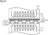
Fig. 13 is a cross-sectional view showing a state in which the resin paint and the conductive film are thermally transferred to the base. - A separator for a fuel cell, a method for producing the separator for the fuel cell, and a method for producing a thermal transfer sheet according to a first embodiment will now be described with reference to
Figs. 1 to 9 . For illustrative purposes, the components in the drawings may be partially exaggerated or simplified, and the dimension of each part may be shown in a ratio that differs from an actual ratio. - As shown in
Fig. 1 , a separator for a fuel cell (hereinafter referred to as the separator 20) is used for astack 100 of a polymer electrolyte fuel cell. Theseparator 20 is a collective term for afirst separator 30 and asecond separator 40, which will be described later. In thestack 100,cells 10 are stacked. Thecells 10 each include apower generation portion 11 having a membrane electrode assembly 12. The membrane electrode assembly 12 is held by thefirst separator 30 and thesecond separator 40. - An anode-side
gas diffusion layer 15, which includes carbon fibers, is arranged between the membrane electrode assembly 12 and thefirst separator 30. A cathode-sidegas diffusion layer 16, which includes carbon fibers, is arranged between the membrane electrode assembly 12 and thesecond separator 40. The membrane electrode assembly 12 includes an electrolyte membrane 13 and twocatalytic electrode layers 14 that hold the electrolyte membrane 13. The electrolyte membrane 13 is made of a solid polymer material that has an excellent proton conductivity in a wet state. Eachcatalytic electrode layer 14 supports a catalyst, such as platinum, in order to expedite the electrochemical reaction of reactant gas in the fuel cell. - The
first separator 30 includes abase 31 made of a metal plate. Thebase 31 is made of, for example, stainless steel. Thebase 31 includesfirst projections 32 and first recesses 33. Thefirst projections 32 and thefirst recesses 33 extend in a surface direction of the base 31 (i.e., a direction that is orthogonal to the sheet ofFig. 1 ) and are alternately arranged. Eachfirst projection 32 is in contact with thepower generation portion 11, more specifically, in contact with the anode-sidegas diffusion layer 15. - The
second separator 40 includes a base 41 made of a metal plate. Thebase 41 is made of, for example, stainless steel. Thebase 41 includessecond projections 42 and second recesses 43. Thesecond projections 42 and thesecond recesses 43 extend in a surface direction of the base 41 (i.e., a direction that is orthogonal to the sheet ofFig. 1 ) and are alternately arranged. Eachsecond projection 42 is in contact with thepower generation portion 11, more specifically, in contact with the cathode-sidegas diffusion layer 16. - The section defined by a portion of the
first separator 30 corresponding to eachfirst recess 33 and the anode-sidegas diffusion layer 15 is a gas passage through which fuel gas (e.g., hydrogen gas) flows. The section defined by a portion of thesecond separator 40 corresponding to eachsecond recess 43 and the cathode-sidegas diffusion layer 16 is a gas passage through which air (e.g., oxidizing gas) flows. - The bottom of each
first recess 33 of thefirst separator 30 and the bottom of the correspondingsecond recess 43 of thesecond separator 40, which is adjacent to thefirst separator 30, are joined to each other through, for example, laser welding. The section defined by a portion of thefirst separator 30 corresponding to the rear surface of eachfirst projection 32 and a portion of thesecond separator 40 corresponding to the rear surface of the correspondingsecond projection 42 is a cooling passage through which coolant flows. - As shown in
Fig. 2 , aresin layer 50 is arranged on the entirety of a first front surface of each of thebases separator 20. The first front surface opposes thepower generation portion 11. Theresin layer 50 is not arranged on a second front surface of each of thebases resin layer 50 includes athermosetting resin 50a, such as epoxy resin. Theresin 50a is an example of a second resin. Further, aconductive layer 60, which has conductivity, is arranged on each of the top surfaces of theprojections bases resin layer 50 located between theconductive layer 60 and the top surface. Eachconductive layer 60 includesconductive carbon materials 61,conductive particles 62, athermosetting resin 63, and a solvent. Theresin 63 is an example of a first resin. - The
conductive carbon materials 61 are, for example, graphite particles. Theconductive particles 62 are, for example, titanium nitrides. Theresin 63 is, for example, epoxy resin. The solvent is, for example, methyl ethyl ketone (MEK). The hardness of titanium nitride is higher than the hardness ofoxide films bases - The
conductive carbon materials 61 and theconductive particles 62 are dispersed in theresin 63 and are in contact with each other over the entirety of theconductive layer 60 in a thickness direction of theconductive layer 60. Theconductive particles 62 extend through theoxide films projections bases separators oxide films bases conductive carbon materials 61, and theconductive particles 62. - The method for producing the
first separator 30 will now be described. The method for producing thesecond separator 40 is the same as the method for producing thefirst separator 30 and thus will not be described. - Referring to
Fig. 3 , theconductive particles 62, theresin 63, the solvent, and the raw materials of theconductive carbon materials 61 are first injected into a grinding device 70 (e.g., jet mill). The raw materials of theconductive carbon materials 61 are ground, and the groundconductive carbon materials 61, theconductive particles 62, theresin 63, and the solvent are mixed. This produces aconductive paint 60a. In theconductive paint 60a, the groundconductive carbon materials 61 and theconductive particles 62 are dispersed in theresin 63. - The result of measuring the viscosity of the
conductive paint 60a will now be described with reference toFig. 4 . Theconductive paint 60a of the first embodiment was used as an example, and a conductive paint containing titanium nitride and epoxy resin was used as comparative example 1. The viscosity of each example was measured.Fig. 4 reveals that the viscosity of the example is larger than the viscosity of comparative example 1. This is presumably because the ground raw materials of theconductive carbon materials 61 are dispersed in theresin 63. - Next, as shown in
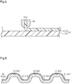
Fig. 5 , acoater 90 is used to apply theconductive paint 60a to one surface of a resin (e.g., polyethylene terephthalate)film 81. This forms aconductive film 60b on the surface of thefilm 81. Athermal transfer sheet 80 is thus produced. - Then, as shown in
Fig. 6 , a spray or the like is used to spray a resin material onto the entire first front surface of thebase 31. This forms theresin layer 50, including theresin 50a. Subsequently, as shown inFig. 7 , thebase 31 is mounted on a fixeddie 111 of athermal transfer apparatus 110 with the first front surface directed upward. Further, thethermal transfer sheet 80 is mounted on thefirst projections 32 of the base 31 with theconductive film 60b directed downward. - Afterwards, as shown in
Fig. 8 , amovable die 115 is lowered toward the fixeddie 111. The fixeddie 111 and themovable die 115 are used to pressurize thebase 31 and thethermal transfer sheet 80. This causes theconductive particles 62 to extend through theresin layer 50 and theoxide film 31a of thebase 31 and contact the base 31 as shown inFig. 2 . - Next, as shown in
Fig. 8 , power is supplied to electrically-heated wires die 111 and themovable die 115. Thebase 31 is heated to a given temperature that is higher than the thermosetting temperature of each of theresin 63 and theresin 50a, which are epoxy resins. This causes theresin layer 50 to be thermally cured and causes theconductive film 60b to be thermally transferred to the top surfaces of theprojections 32 of thebase 31, thereby forming theconductive layer 60. Lastly, although not shown in the drawings, themovable die 115 is separated from the fixeddie 111 to remove thefirst separator 30 from thethermal transfer apparatus 110. Thefirst separator 30 is thus produced. - The result of measuring the contact resistance in the
conductive layer 60 will now be described with reference toFig. 9 . The result of measuring the contact resistance in theconductive layer 60 of the first embodiment, which was used as the example, the conductive layer of comparative example 1, the conductive layer of comparative example 2, and the conductive layer of comparative example 3 will now be described. - First, the structures of comparative examples 1 to 3 will be described. Comparative example 1 includes titanium nitride and epoxy resin. Comparative example 2 includes graphite particles and epoxy resin. Comparative example 3 includes a first layer and a second layer. The first layer is arranged on each of the front surfaces of the
bases - The contact resistance in each example was measured as follows. First, two carbon clothes were used to hold test pieces of the
bases bases gas diffusion layer 15 and the cathode-sidegas diffusion layer 16. -
Fig. 9 reveals that the contact resistance in the example is lower than the contact resistances in comparative examples 1 to 3. As described above, comparative example 1 has a lower viscosity than the example. Thus, in the conductive layer of comparative example 1, it is presumed that when the titanium nitrides settle in the epoxy resin, the titanium nitrides are unevenly distributed in the thickness direction of the conductive layer. - In comparative example 2, it is presumed that conductive passages are defined by graphite particles, which have a smaller conductivity than titanium nitrides. In comparative example 3, the first layer includes titanium nitrides and the second layer includes graphite particles. Thus, it is presumed that conductive passages are defined by the titanium nitrides in the first layer and conductive passage are defined by the graphite particles in the second layer.
- The example has a higher viscosity than comparative example 1. Thus, it is presumed that graphite particles (conductive carbon materials 61) and titanium nitrides (conductive particles 62) are easily dispersed in the epoxy resin (resin 63) over the entirety of the
conductive layer 60 in the thickness direction. Thus, conductive passages going through the graphite particles (conductive carbon materials 61) and the titanium nitrides (conductive particles 62) are easily defined over the entirety of theconductive layer 60 in the thickness direction. Accordingly, it is presumed that the contact resistance in the example is lower than the contact resistances in comparative examples 1 to 3. - The operation of the first embodiment will now be described.
- In the
conductive layer 60, theconductive carbon materials 61 and theconductive particles 62 are dispersed in theresin 63 and are in contact with each other over the entirety of theconductive layer 60 in the thickness direction. Thus, conductive passages going through theconductive carbon materials 61 and theconductive particles 62 are defined in theconductive layer 60 in the thickness direction. This increases the conductivity of the conductive layer 60 (operation 1). - Further, in order to produce the
conductive layer 60, thethermal transfer sheet 80 in which theconductive paint 60a is applied to thefilm 81 is used. Theconductive carbon materials 61 and theconductive particles 62 are dispersed in the entirety of theresin 63. Thus, in theconductive layer 60 arranged on each of theprojections bases conductive carbon materials 61 and theconductive particles 62 are easily dispersed over the entirety of theconductive layer 60 in the thickness direction. Accordingly, conductive passages going through theconductive carbon materials 61 and theconductive particles 62 are easily defined in the conductive layer 60 (operation 2). - When the
conductive paint 60a including theconductive carbon materials 61, theconductive particles 62, and thethermosetting resin 63 is applied to one surface of thefilm 81, theconductive particles 62 potentially settle downward (i.e., settle toward the film 81) due to the weights of theconductive particles 62. Thus, in theconductive paint 60a, theconductive carbon materials 61 that have been ground to become minute are dispersed in the entirety of theresin 63. Accordingly, the viscosity of theconductive paint 60a is higher than the viscosity of theconductive paint 60a that includes theconductive carbon materials 61 prior to being ground. This limits situations in which theconductive particles 62 settle toward thefilm 81 in theconductive paint 60a, which is applied to the surface of the film 81 (operation 3). - The advantages of the first embodiment will now be described.
- (1) The
separator 20 includes thebases bases projections conductive layers 60 are arranged on the top surfaces of theprojections bases conductive layer 60 includes theconductive carbon materials 61, theconductive particles 62, and thethermosetting resin 63. Theconductive carbon materials 61 and theconductive particles 62 are dispersed in theresin 63 and are in contact with each other over the entirety of theconductive layer 60 in the thickness direction. This structure providesoperation 1 and thus reduces the contact resistance between theseparator 20 and thepower generation portion 11. - (2) To produce the
separator 20, thethermal transfer sheet 80 is used. In thethermal transfer sheet 80, theconductive paint 60a is applied to thefilm 81 so that theconductive film 60b is formed on thefilm 81. Thebases thermal transfer sheet 80 in contact with the top surfaces of theprojections conductive film 60b to be thermally transferred to the top surfaces of theprojections conductive layers 60 on the top surfaces of theprojections operation 2 and thus reduces the contact resistance between theseparator 20 and thepower generation portion 11. - (3) The raw materials of the
conductive carbon materials 61 are ground, and the groundconductive carbon materials 61, theconductive particles 62, and theresin 63 are mixed. As a result, theconductive paint 60a is produced. This method providesoperation 3 and thus easily produces theconductive paint 60a in which the groundconductive carbon materials 61 and theconductive particles 62 are dispersed in the entirety of thethermosetting resin 63. Accordingly, thethermal transfer sheet 80 in which theconductive paint 60a is applied to thefilm 81 is produced. - (4) Before the
conductive film 60b is thermally transferred to each of the top surfaces of theprojections conductive layer 60, theresin layer 50 including thethermosetting resin 50a is formed on the entire first front surface of each of thebases power generation portion 11. In this method, theresin layer 50 is formed on the entire first front surface of each of thebases power generation portion 11, and theconductive layer 60 is then formed on each of theprojections bases resin 63, which is included in theconductive layer 60 and corresponds to the first resin, and theresin 50a, which is included in theresin layer 50 and corresponds to the second resin, are thermosetting resins. Thus, theresin 63 and theresin 50a are thermally cured by heating thebases separator 20 is obtained in such a manner. In this structure, the entire first front surface of each of thebases power generation portion 11 is covered by theresin layer 50. This prevents the elution of ions from the first front surface of each of thebases - (5) To produce the
thermal transfer sheet 80, theconductive paint 60a is applied to one surface of thefilm 81 to form theconductive film 60b on the surface of thefilm 81. Theconductive paint 60a is produced by dispersing theconductive carbon materials 61 and theconductive particles 62 in the entirety of thethermosetting resin 63. This method provides an advantage similar to advantage (2). - A separator for a fuel cell, a method for producing the separator for the fuel cell, and a method for producing a thermal transfer sheet according to a second embodiment will now be described with reference to
Figs. 10 to 13 . Differences from the first embodiment will be mainly described. - In the second embodiment, like or the same reference numerals are given to those components that are like or the same as the corresponding components of the first embodiment. Further, the components that correspond to those in the first embodiment are given reference numbers "2∗∗" obtained by adding 200 to reference numbers "∗∗" of the first embodiment and will not be described. For illustrative purposes, the components in the drawings may be partially exaggerated or simplified, and the dimension of each part may be shown in a ratio that differs from an actual ratio.
- As shown in
Fig. 10 , a separator 220 includes aresin layer 250 arranged only on each top surface of theprojections bases bases resin layer 250 includes a thermosetting resin 250a, such as epoxy resin. The resin 250a is an example of the second resin. Further, theconductive layer 60 is arranged on each of the top surfaces of theprojections bases resin layer 250 located between theconductive layer 60 and the top surface. - The method for producing a first separator 230 will now be described. The method for producing a second separator 240 is the same as the method for producing the first separator 230 and thus will not be described. The steps that are the same as those of the first embodiment will not be described.
- As shown in
Fig. 11 , acoater 290 is used to apply theconductive paint 60a to one surface of thefilm 81 to form theconductive film 60b on the surface of thefilm 81. Next, aresin paint 250b including the resin 250a is applied to the front surface of theconductive film 60b. Athermal transfer sheet 280 is thus produced. - Next, as shown in
Fig. 12 , thethermal transfer sheet 280 is mounted on thefirst projections 32 of the base 31 with theresin paint 250b directed downward. Afterwards, as shown inFig. 13 , themovable die 115 is lowered toward the fixeddie 111. The fixeddie 111 and themovable die 115 are used to pressurize and heat thebase 31 and thethermal transfer sheet 280. This causes theresin paint 250b and theconductive film 60b to be thermally transferred to the top surfaces of theprojections 32 to form theresin layer 250 and theconductive layers 60 on the top surfaces of theprojections 32 as shown inFig. 10 . The first separator 230 is thus produced. - The operation of the second embodiment will now be described.
- The
thermal transfer sheet 280 in which theconductive paint 60a and theresin paint 250b are applied to thefilm 81 is used. This forms theresin layer 250 and theconductive layer 60 on each of the top surfaces of theprojections bases conductive layer 60 is arranged on each of theprojections bases resin layer 250 located between theconductive layer 60 and theprojection conductive layer 60 to be in closer contact with the top surfaces of theprojections bases conductive layer 60 and the front surfaces of theprojections bases - The advantages of the second embodiment will now be described.
- The separator 220 of the second embodiment, the method for producing the separator 220, and the method for producing the
thermal transfer sheet 280 according to the second embodiment provide the following advantage in addition to advantages (1) to (3) and (5) of the first embodiment. - (6) To produce the separator 220, the
resin paint 250b including the thermosetting resin 250a is applied to the front surface of theconductive paint 60a of thefilm 81. This method provides operation 4 and thus reduces the contact resistance between the separator 220 and thepower generation portion 11. - The above-described embodiments may be modified as follows. The above-described embodiments and the following modifications can be combined as long as the combined modifications remain technically consistent with each other.
- The
resin layer 50 may be arranged on two surfaces of each of thebases - The formation of the
resin layer 50 may be omitted. In this case, theconductive layer 60 is directly formed on each of the top surfaces of theprojections bases resin layer 250 may also be omitted. In this case, theconductive layer 60 is directly formed on each of the top surfaces of theprojections bases - The
resin 63, which corresponds to the first resin, may be a thermosetting resin of a type that differs from theresin 50a, which corresponds to the second resin. Theresin 63, which corresponds to the first resin, may be a thermosetting resin of a type that differs from the resin 250a, which corresponds to the second resin. - After only the raw materials of the
conductive carbon materials 61 are ground using the grindingdevice 70, the groundconductive carbon materials 61, theconductive particles 62, theresin 63, and the solvent may be mixed. - The
conductive paint 60a may be produced by preparingconductive carbon materials 61 having a given size in advance and mixing theconductive carbon materials 61, theconductive particles 62, theresin 63, and the solvent. - The
conductive particles 62 may be ground using the grindingdevice 70. - The grinding device may be a device other than a jet mill. For example, a bead mill may be used.
- In addition to or instead of graphite particles, another type of conductive carbon material such as carbon black may be used.
- Instead of titanium nitride, another type of conductive particles such as titanium carbide or titanium boride may be used.
- The base material 31.41 may be made of a metal plate other than stainless steel or titanium alloy. Examples of the metal include aluminum alloy and magnesium alloy.
- The
resins
Claims (6)
- A separator for a fuel cell, the separator comprising:a base including projections, the base being made of a metal plate; anda conductive layer including conductive carbon materials, conductive particles, and a thermosetting resin, the conductive layer being arranged on a top surface of each of the projections of the base such that the conductive layer is in contact with a power generation portion of the fuel cell,wherein the conductive carbon materials and the conductive particles are dispersed in the resin and are in contact with each other over an entirety of the conductive layer in a thickness direction of the conductive layer.
- A method for producing a separator for a fuel cell,
the separator for the fuel cell including:a base including projections, the base being made of a metal plate; anda conductive layer including conductive carbon materials, conductive particles, and a thermosetting resin, the conductive layer being arranged on a top surface of each of the projections of the base such that the conductive layer is in contact with a power generation portion of the fuel cell,the method comprising:applying a conductive paint to a film to form a thermal transfer sheet, the conductive paint being produced by dispersing the conductive carbon materials and the conductive particles in an entirety of the resin; andpressurizing the thermal transfer sheet against the base and heating the thermal transfer sheet with the thermal transfer sheet in contact with each of the top surfaces of the projections, thereby thermally transferring the conductive paint to the each of the top surfaces of the projections and forming the conductive layer on the each of the top surfaces of the projections. - The method according to claim 2, wherein the conductive carbon materials are produced by grinding raw materials of the conductive carbon materials and mixing the ground conductive carbon materials, the conductive particles, and the resin.
- The method according to claim 2 or 3, whereinthe resin is a first resin, andbefore the conductive paint is thermally transferred to the each of the top surfaces of the projections to form the conductive layer on the each of the top surfaces of the projections, a resin layer including a thermosetting second resin is formed on an entirety of a front surface of the base opposing the power generation portion.
- The method according to claim 2 or 3, whereinthe resin is a first resin, anda resin paint including a thermosetting second resin is applied to a front surface of the conductive paint of the film.
- A method for producing a thermal transfer sheet, the thermal transfer sheet being used to thermally transfer a conductive film on a front surface of a base of a separator for a fuel cell and form a conductive layer on the front surface by pressurizing and heating the thermal transfer sheet in contact with the front surface,
the method comprising:
forming the conductive film on one surface of a film by applying a conductive paint to the surface of the film, the conductive paint being produced by dispersing conductive carbon materials and conductive particles in an entirety of a thermosetting resin.
Applications Claiming Priority (2)
| Application Number | Priority Date | Filing Date | Title |
|---|---|---|---|
| JP2019203746A JP7247864B2 (en) | 2019-11-11 | 2019-11-11 | Separator for fuel cell, method for producing separator for fuel cell, and method for producing thermal transfer sheet |
| PCT/JP2020/031116 WO2021095312A1 (en) | 2019-11-11 | 2020-08-18 | Separator for fuel cells, method for producing separator for fuel cells, and method for producing sheet for thermal transfer |
Publications (2)
| Publication Number | Publication Date |
|---|---|
| EP4060773A1 true EP4060773A1 (en) | 2022-09-21 |
| EP4060773A4 EP4060773A4 (en) | 2024-10-02 |
Family
ID=75899836
Family Applications (1)
| Application Number | Title | Priority Date | Filing Date |
|---|---|---|---|
| EP20886202.9A Pending EP4060773A4 (en) | 2019-11-11 | 2020-08-18 | SEPARATOR FOR FUEL CELLS, METHOD FOR PRODUCING A SEPARATOR FOR FUEL CELLS AND METHOD FOR PRODUCING A HEAT TRANSFER FILM |
Country Status (5)
| Country | Link |
|---|---|
| US (1) | US12021273B2 (en) |
| EP (1) | EP4060773A4 (en) |
| JP (1) | JP7247864B2 (en) |
| CN (1) | CN114270581B (en) |
| WO (1) | WO2021095312A1 (en) |
Family Cites Families (14)
| Publication number | Priority date | Publication date | Assignee | Title |
|---|---|---|---|---|
| JP2002050366A (en) * | 2000-08-07 | 2002-02-15 | Hitachi Ltd | Solid polymer fuel cell metal separator and fuel cell using the same |
| WO2005027248A1 (en) | 2003-09-10 | 2005-03-24 | Mitsubishi Plastics, Inc. | Fuel cell separator |
| JP2006172719A (en) * | 2004-12-10 | 2006-06-29 | Japan Carlit Co Ltd:The | Fuel cell separator and method for producing the same |
| US9099690B2 (en) | 2005-06-17 | 2015-08-04 | University Of Yamanashi | Metallic separator for fuel cells and method of manufacturing the metallic separator |
| JP2009224294A (en) | 2008-03-19 | 2009-10-01 | Toppan Printing Co Ltd | Manufacturing method for fuel cell separator |
| JP2009230880A (en) | 2008-03-19 | 2009-10-08 | Toppan Printing Co Ltd | Manufacturing method of separator for fuel cell |
| JP2010065257A (en) | 2008-09-09 | 2010-03-25 | Toyota Auto Body Co Ltd | Surface treatment method for metal sheet and metal separator for fuel cell |
| JP5930036B2 (en) * | 2012-07-11 | 2016-06-08 | トヨタ車体株式会社 | Fuel cell separator and method for producing fuel cell separator |
| JP6402831B2 (en) | 2015-08-31 | 2018-10-10 | トヨタ車体株式会社 | Fuel cell separator coating film forming apparatus and fuel cell separator |
| JP6620711B2 (en) * | 2016-09-30 | 2019-12-18 | トヨタ車体株式会社 | Manufacturing method of thermal transfer sheet |
| JP6812945B2 (en) | 2017-10-18 | 2021-01-13 | トヨタ自動車株式会社 | Manufacturing method of separator for fuel cell |
| WO2019082591A1 (en) * | 2017-10-25 | 2019-05-02 | Jfeスチール株式会社 | Method for producing stainless steel plate for fuel cell separator |
| JP2019121523A (en) * | 2018-01-09 | 2019-07-22 | トヨタ車体株式会社 | Method of manufacturing fuel cell separator |
| JP7010077B2 (en) | 2018-03-13 | 2022-02-10 | トヨタ車体株式会社 | Method for manufacturing a fuel cell separator joint and a fuel cell separator joint |
-
2019
- 2019-11-11 JP JP2019203746A patent/JP7247864B2/en active Active
-
2020
- 2020-08-18 EP EP20886202.9A patent/EP4060773A4/en active Pending
- 2020-08-18 WO PCT/JP2020/031116 patent/WO2021095312A1/en not_active Ceased
- 2020-08-18 US US17/634,900 patent/US12021273B2/en active Active
- 2020-08-18 CN CN202080056814.0A patent/CN114270581B/en active Active
Also Published As
| Publication number | Publication date |
|---|---|
| EP4060773A4 (en) | 2024-10-02 |
| CN114270581B (en) | 2024-08-30 |
| CN114270581A (en) | 2022-04-01 |
| JP2021077527A (en) | 2021-05-20 |
| US20220328849A1 (en) | 2022-10-13 |
| JP7247864B2 (en) | 2023-03-29 |
| US12021273B2 (en) | 2024-06-25 |
| WO2021095312A1 (en) | 2021-05-20 |
Similar Documents
| Publication | Publication Date | Title |
|---|---|---|
| US8197632B2 (en) | Method for producing fuel cell electrolyte membrane and method for producing membrane-electrode assembly | |
| US10658683B2 (en) | Method for producing electrolyte membrane electrode assembly for fuel cells | |
| EP1586132B1 (en) | One-step method of bonding and sealing a fuel cell membrane electrode assembly | |
| EP1919015B1 (en) | Metal separator for fuel cell and manufacturing method thereof | |
| US8795918B2 (en) | Single fuel cell and fuel cell stack | |
| US11075395B2 (en) | Fuel cell membrane electrode assembly (MEA) with hexagonal boron nitride thin film | |
| EP1484810A1 (en) | Method for manufacturing polymer electrolyte type fuel cell | |
| EP1378953A1 (en) | Polymer electrolyte fuel cell and production method of separator plate thereof | |
| KR101710253B1 (en) | Fuel cell gas diffusion layer and method for forming same | |
| US20120282539A1 (en) | Fuel cell | |
| JP5135341B2 (en) | Manufacturing method of separator plate for fuel cell and fuel cell using the same | |
| JP2008300347A (en) | Method for producing 5-layer MEA with improved electrical conductivity | |
| US8808942B2 (en) | Adhesive for fuel cell and membrane-electrode assembly produced using the same | |
| US20100298119A1 (en) | Fuel cell electrode and method for producing the same | |
| US12021273B2 (en) | Method for producing separator for fuel cells | |
| CN102437301A (en) | Composite separator for polymer electrolyte membrane fuel cell and method for manufacturing the same | |
| US8431285B2 (en) | Edge design for ePTFE-reinforced membranes for PEM fuel cells | |
| CN109546175B (en) | Method for manufacturing fuel cell separator | |
| JP7375721B2 (en) | Separator and separator manufacturing method | |
| JP7095588B2 (en) | Surface treatment method for fuel cell separators | |
| JP4240285B2 (en) | Method for producing gas diffusion layer of polymer electrolyte fuel cell | |
| JP2005251676A (en) | Separator manufacturing method | |
| JP7276250B2 (en) | METHOD FOR MANUFACTURING FUEL CELL SEPARATOR | |
| JP2025025209A (en) | Manufacturing method of fuel cell separator | |
| JP2006134677A (en) | Separator for polymer electrolyte fuel cell and method for producing the same |
Legal Events
| Date | Code | Title | Description |
|---|---|---|---|
| STAA | Information on the status of an ep patent application or granted ep patent |
Free format text: STATUS: THE INTERNATIONAL PUBLICATION HAS BEEN MADE |
|
| PUAI | Public reference made under article 153(3) epc to a published international application that has entered the european phase |
Free format text: ORIGINAL CODE: 0009012 |
|
| STAA | Information on the status of an ep patent application or granted ep patent |
Free format text: STATUS: REQUEST FOR EXAMINATION WAS MADE |
|
| 17P | Request for examination filed |
Effective date: 20220211 |
|
| AK | Designated contracting states |
Kind code of ref document: A1 Designated state(s): AL AT BE BG CH CY CZ DE DK EE ES FI FR GB GR HR HU IE IS IT LI LT LU LV MC MK MT NL NO PL PT RO RS SE SI SK SM TR |
|
| DAV | Request for validation of the european patent (deleted) | ||
| DAX | Request for extension of the european patent (deleted) | ||
| A4 | Supplementary search report drawn up and despatched |
Effective date: 20240904 |
|
| RIC1 | Information provided on ipc code assigned before grant |
Ipc: C23C 28/00 20060101ALI20240829BHEP Ipc: H01M 8/10 20160101ALI20240829BHEP Ipc: H01M 8/0254 20160101ALI20240829BHEP Ipc: H01M 8/0228 20160101ALI20240829BHEP Ipc: H01M 8/0221 20160101ALI20240829BHEP Ipc: H01M 8/0213 20160101ALI20240829BHEP Ipc: H01M 8/0206 20160101AFI20240829BHEP |