EP4060772A1 - Method for producing a conductor foil for batteries - Google Patents
Method for producing a conductor foil for batteries Download PDFInfo
- Publication number
- EP4060772A1 EP4060772A1 EP22162131.1A EP22162131A EP4060772A1 EP 4060772 A1 EP4060772 A1 EP 4060772A1 EP 22162131 A EP22162131 A EP 22162131A EP 4060772 A1 EP4060772 A1 EP 4060772A1
- Authority
- EP
- European Patent Office
- Prior art keywords
- cutting
- feed direction
- foil
- roll
- feed
- Prior art date
- Legal status (The legal status is an assumption and is not a legal conclusion. Google has not performed a legal analysis and makes no representation as to the accuracy of the status listed.)
- Pending
Links
- 239000011888 foil Substances 0.000 title claims abstract description 75
- 239000004020 conductor Substances 0.000 title claims abstract description 61
- 238000004519 manufacturing process Methods 0.000 title claims abstract description 42
- 238000003698 laser cutting Methods 0.000 claims abstract description 46
- 238000000034 method Methods 0.000 claims abstract description 27
- 238000005520 cutting process Methods 0.000 claims description 77
- 229910052751 metal Inorganic materials 0.000 description 10
- 239000002184 metal Substances 0.000 description 10
- 239000011149 active material Substances 0.000 description 7
- 238000004080 punching Methods 0.000 description 7
- 238000004804 winding Methods 0.000 description 7
- 239000003792 electrolyte Substances 0.000 description 4
- RYGMFSIKBFXOCR-UHFFFAOYSA-N Copper Chemical compound [Cu] RYGMFSIKBFXOCR-UHFFFAOYSA-N 0.000 description 3
- 229910052782 aluminium Inorganic materials 0.000 description 3
- XAGFODPZIPBFFR-UHFFFAOYSA-N aluminium Chemical compound [Al] XAGFODPZIPBFFR-UHFFFAOYSA-N 0.000 description 3
- 239000002482 conductive additive Substances 0.000 description 3
- 239000011889 copper foil Substances 0.000 description 3
- 239000000463 material Substances 0.000 description 3
- OKTJSMMVPCPJKN-UHFFFAOYSA-N Carbon Chemical compound [C] OKTJSMMVPCPJKN-UHFFFAOYSA-N 0.000 description 2
- HBBGRARXTFLTSG-UHFFFAOYSA-N Lithium ion Chemical compound [Li+] HBBGRARXTFLTSG-UHFFFAOYSA-N 0.000 description 2
- 239000011230 binding agent Substances 0.000 description 2
- 239000011248 coating agent Substances 0.000 description 2
- 238000000576 coating method Methods 0.000 description 2
- 238000011161 development Methods 0.000 description 2
- 230000018109 developmental process Effects 0.000 description 2
- 238000004146 energy storage Methods 0.000 description 2
- 239000010439 graphite Substances 0.000 description 2
- 229910002804 graphite Inorganic materials 0.000 description 2
- 150000002500 ions Chemical class 0.000 description 2
- 235000015110 jellies Nutrition 0.000 description 2
- 239000008274 jelly Substances 0.000 description 2
- 229910001416 lithium ion Inorganic materials 0.000 description 2
- BFZPBUKRYWOWDV-UHFFFAOYSA-N lithium;oxido(oxo)cobalt Chemical compound [Li+].[O-][Co]=O BFZPBUKRYWOWDV-UHFFFAOYSA-N 0.000 description 2
- VNWKTOKETHGBQD-UHFFFAOYSA-N methane Chemical compound C VNWKTOKETHGBQD-UHFFFAOYSA-N 0.000 description 2
- 230000003287 optical effect Effects 0.000 description 2
- 239000010935 stainless steel Substances 0.000 description 2
- 229910001220 stainless steel Inorganic materials 0.000 description 2
- 229910000838 Al alloy Inorganic materials 0.000 description 1
- 229910000831 Steel Inorganic materials 0.000 description 1
- 230000001133 acceleration Effects 0.000 description 1
- 239000010426 asphalt Substances 0.000 description 1
- 239000002800 charge carrier Substances 0.000 description 1
- 238000002485 combustion reaction Methods 0.000 description 1
- 239000004567 concrete Substances 0.000 description 1
- 230000001419 dependent effect Effects 0.000 description 1
- 238000004512 die casting Methods 0.000 description 1
- 230000000694 effects Effects 0.000 description 1
- 239000007788 liquid Substances 0.000 description 1
- 229910021450 lithium metal oxide Inorganic materials 0.000 description 1
- 239000007787 solid Substances 0.000 description 1
- 239000010959 steel Substances 0.000 description 1
- 238000003860 storage Methods 0.000 description 1
- 239000011269 tar Substances 0.000 description 1
Images


Classifications
-
- H—ELECTRICITY
- H01—ELECTRIC ELEMENTS
- H01M—PROCESSES OR MEANS, e.g. BATTERIES, FOR THE DIRECT CONVERSION OF CHEMICAL ENERGY INTO ELECTRICAL ENERGY
- H01M4/00—Electrodes
- H01M4/02—Electrodes composed of, or comprising, active material
- H01M4/64—Carriers or collectors
-
- B—PERFORMING OPERATIONS; TRANSPORTING
- B23—MACHINE TOOLS; METAL-WORKING NOT OTHERWISE PROVIDED FOR
- B23K—SOLDERING OR UNSOLDERING; WELDING; CLADDING OR PLATING BY SOLDERING OR WELDING; CUTTING BY APPLYING HEAT LOCALLY, e.g. FLAME CUTTING; WORKING BY LASER BEAM
- B23K26/00—Working by laser beam, e.g. welding, cutting or boring
- B23K26/36—Removing material
- B23K26/38—Removing material by boring or cutting
-
- H—ELECTRICITY
- H01—ELECTRIC ELEMENTS
- H01B—CABLES; CONDUCTORS; INSULATORS; SELECTION OF MATERIALS FOR THEIR CONDUCTIVE, INSULATING OR DIELECTRIC PROPERTIES
- H01B13/00—Apparatus or processes specially adapted for manufacturing conductors or cables
-
- B—PERFORMING OPERATIONS; TRANSPORTING
- B23—MACHINE TOOLS; METAL-WORKING NOT OTHERWISE PROVIDED FOR
- B23K—SOLDERING OR UNSOLDERING; WELDING; CLADDING OR PLATING BY SOLDERING OR WELDING; CUTTING BY APPLYING HEAT LOCALLY, e.g. FLAME CUTTING; WORKING BY LASER BEAM
- B23K26/00—Working by laser beam, e.g. welding, cutting or boring
- B23K26/08—Devices involving relative movement between laser beam and workpiece
- B23K26/083—Devices involving movement of the workpiece in at least one axial direction
-
- H—ELECTRICITY
- H01—ELECTRIC ELEMENTS
- H01M—PROCESSES OR MEANS, e.g. BATTERIES, FOR THE DIRECT CONVERSION OF CHEMICAL ENERGY INTO ELECTRICAL ENERGY
- H01M4/00—Electrodes
- H01M4/02—Electrodes composed of, or comprising, active material
- H01M4/04—Processes of manufacture in general
-
- B—PERFORMING OPERATIONS; TRANSPORTING
- B23—MACHINE TOOLS; METAL-WORKING NOT OTHERWISE PROVIDED FOR
- B23K—SOLDERING OR UNSOLDERING; WELDING; CLADDING OR PLATING BY SOLDERING OR WELDING; CUTTING BY APPLYING HEAT LOCALLY, e.g. FLAME CUTTING; WORKING BY LASER BEAM
- B23K2101/00—Articles made by soldering, welding or cutting
- B23K2101/36—Electric or electronic devices
-
- H—ELECTRICITY
- H01—ELECTRIC ELEMENTS
- H01M—PROCESSES OR MEANS, e.g. BATTERIES, FOR THE DIRECT CONVERSION OF CHEMICAL ENERGY INTO ELECTRICAL ENERGY
- H01M10/00—Secondary cells; Manufacture thereof
- H01M10/05—Accumulators with non-aqueous electrolyte
- H01M10/052—Li-accumulators
- H01M10/0525—Rocking-chair batteries, i.e. batteries with lithium insertion or intercalation in both electrodes; Lithium-ion batteries
Definitions
- the invention relates to a method for producing a conductor foil for batteries and a production device.
- a high-voltage battery which comprises a number of individual battery modules, is usually used to power the electric motor.
- the battery modules are usually structurally identical to one another and are electrically connected to one another in series and/or in parallel, so that the electrical voltage present at the high-voltage battery corresponds to a multiple of the electrical voltage provided by each of the battery modules.
- Each battery module in turn comprises a plurality of batteries which are usually arranged in a common housing and which are electrically connected to one another in series and/or in parallel.
- Each of the batteries usually includes a number of battery cells, each of which is also referred to as a galvanic element. These each have two electrodes, namely an anode and a cathode, as well as a separator arranged between them and an electrolyte with freely mobile charge carriers. A liquid, for example, is used as such an electrolyte.
- the battery is in the form of a solid-state battery and the electrolyte is in the form of a solid.
- the anode and the cathode, which form the electrodes of the battery cell usually include a current conductor, also referred to simply as a conductor or carrier.
- An active material which is part of a layer applied to the carrier, is usually attached to this. It is possible that the electrolyte is already present in the layer, or that it is introduced later. However, the active material is at least suitable for absorbing the working ions, eg lithium ions. Depending on whether it is used as an anode or cathode, a different material is used for the support and a different type of material for the layer.
- the conductors are usually made from a metal foil, so that the thickness of the electrodes is comparatively small.
- the metal foil is usually initially in the form of a raw foil in the form of a roll.
- the layer is applied to this and then cured.
- the roll goods are then cut to length so that the respective electrode is created.
- the layer is not applied to the entire surface of the raw film, but an edge area is left free of the layer, so that direct electrical contacting with the arrester is made possible there. Only a comparatively small section of the edge area is required for this, and the remaining part of the edge area is not required. So that this space can be used for other purposes, the edge area in this part is usually cut out, this usually being done before the layer is applied.
- the raw film is first unwound and fed to a punching machine to make a cut-out. This is used to punch the edge area so that the sections remain as connections and the remaining parts are separated.
- the raw film processed in this way is then wound up again and can be temporarily stored. Direct further processing, in particular the provision of the layer, is also possible.
- the unwound section of the raw film to be punched is not moved.
- the section of the roll is unwound and fed into the punching machine.
- the roll is then stopped and the punching machine is activated.
- This punching machine is then removed from the punching machine, for which purpose the roll is unwound again and a new section of the raw film is thus fed to the punching machine. Consequently, the raw film is processed in a cycled manner.
- a comparatively high load acts on the raw film.
- a maximum acceleration and deceleration is specified. Thus, it is not possible to increase the manufacturing speed beyond a certain level.
- the invention is based on the object of specifying a particularly suitable method for producing a collector foil for batteries and a particularly suitable production device for producing a collector foil, flexibility being advantageously increased and/or rejects being reduced.
- the process is used to produce a conductor foil for batteries. For example, it is possible to create only a single conductor from the conductor foil. However, it is particularly preferably possible to create a number of conductors from the conductor foil.
- the created arresters are each a component of an electrode of the respective battery.
- the electrodes created by means of the conductor foil are, for example, anodes or cathodes.
- Each of the electrodes expediently comprises a layer which is applied to the respective collector.
- the layer has, in particular, an active material that is suitable and provided and set up to absorb working ions, such as lithium ions.
- a lithium metal oxide such as lithium cobalt(III) oxide (LiCoO2), NMC, NCA, LFP, GIC, LTO, for example, is used as the active material.
- LiCoO2 lithium cobalt(III) oxide
- NMC NMC
- NCA lithium cobalt(III) oxide
- LFP low-density polyethylene
- GIC lithium cobalt(III) oxide
- LTO lithium cobalt(III) oxide
- NMC622 or NMC811 is used as the active material.
- the battery thus includes a cell stack.
- the conductor foil or at least part of it is wound up and the battery comprises a so-called “jelly roll”.
- the batteries produced are preferably a component part of a motor vehicle.
- the batteries are suitable for this, in particular provided and set up.
- the batteries are, for example, part of an energy store in the motor vehicle, which has a number of such batteries.
- the batteries are preferably divided among a number of battery modules, which in turn are structurally identical to one another.
- the batteries are arranged in particular in a housing of the energy store or of the respective battery module and are electrically connected to one another in parallel and/or in series.
- the electrical voltage applied to the energy store/battery module is therefore a multiple of the electrical voltage provided by each of the batteries.
- the housing of the energy store or of the respective battery module is preferably made of a metal, for example steel, such as stainless steel, or an aluminum alloy. A die-casting process, for example, is used to produce it.
- the housing of the energy store or of the respective battery module is designed to be closed.
- An interface is expediently introduced into the housing of the energy store or the respective battery module, which connects the Energy storage / battery module forms. The interface is in electrical contact with the batteries, so that it is possible to feed in electrical energy and/or to draw electrical energy from the batteries from outside the energy store, provided that a corresponding plug is plugged into the connection.
- the motor vehicle is preferably land-based and preferably has a number of wheels, of which at least one, preferably several or all, are driven by a drive.
- one, preferably several, of the wheels is designed to be steerable. It is thus possible to move the motor vehicle independently of a specific roadway, for example rails or the like. It is expediently possible to position the motor vehicle essentially anywhere on a roadway that is made of asphalt, tar or concrete in particular.
- the motor vehicle is, for example, a commercial vehicle, such as a truck (truck) or a bus. However, the motor vehicle is particularly preferably a passenger car.
- the motor vehicle is expediently moved by means of the drive.
- the drive in particular the main drive, is designed at least partially electrically, and the motor vehicle is an electric vehicle, for example.
- the electric motor is operated, for example, by means of the energy store, which is suitably designed as a high-voltage battery.
- An electrical DC voltage is expediently provided by means of the high-voltage battery, the electrical voltage being between 200 V and 800 V, for example, and essentially 400 V, for example.
- An electrical converter is preferably arranged between the energy store and the electric motor, by means of which the energization of the electric motor is adjusted.
- the drive also has an internal combustion engine, so that the motor vehicle is designed as a hybrid motor vehicle.
- a low-voltage electrical system of the motor vehicle is fed by means of the energy store, and by means of the energy store, in particular, an electrical DC voltage of 12 V, 24 V or 48 V is provided.
- the battery is a component of an industrial truck, an industrial plant, a hand-held device, such as a tool, in particular a cordless screwdriver.
- the battery is part of an energy supply and is used there, for example, as a so-called backup battery.
- the battery is part of a portable device, for example a portable mobile phone, or another wearable. It is also possible such a Battery to be used in camping, model making or for other outdoor activities.
- the method provides that a roll with a metallic raw foil is initially provided.
- the raw film is rolled up into the roll.
- the raw foil is made of a metal, the metal being matched to the type of electrode that is to be created using the respective conductor made from the conductor foil.
- a copper foil is used for a conductor foil from which anodes are to be produced, and an aluminum foil is preferably used for conductors which are to be used to produce cathodes.
- the raw foil consists only of bare metal.
- a coating is already present on the metal, in particular a layer. This is present, for example, only on one side or on both sides of the metal.
- the layer has, for example, the respective active material, a binder and/or a conductive additive, such as conductive carbon black or conductive graphite.
- the rolls are continuously unrolled at a feed rate in a feed direction.
- the feed direction is perpendicular to the axis around which the raw film is wound and around which the roll is rotated for unwinding.
- the feed rate is, for example, constant or adapted to current requirements. In particular, this is initially increased at the beginning of the method until a desired speed is reached.
- the feed speed corresponds to a speed at which the roll is unwound.
- the part of the raw film that is unwound is fed to a laser cutting group.
- connections are cut out in an edge area of the unwound raw film by means of the laser cutting group while the roll is being unwound.
- the leads cut out by the laser cutting group remain on the remaining components of the raw film, and the components located between the leads in the direction of feed are severed from the rest of the raw film.
- the terminals have a rectangular shape and the edge area extends along the full feed direction.
- the edge area extends from an edge of the raw film, which extends along the feed direction, to a central area and corresponds, for example, to a maximum of 10%, 5% or 2% of the extension perpendicular to the edge.
- the edge area is expediently free of the layer. If the layer does not already exist, it will suitably subsequently only the area not formed by means of the terminals is coated.
- the distance between the connections in the feed direction, which are cut out by means of the laser cutting group, is constant, for example. In this case, several conductors of the same type are expediently created using the conductor foil, and the electrodes created using the conductors are, in particular, stacked one on top of the other. As an alternative to this, the distance between the connections changes in the feed direction, and an electrode which is wound up, in particular to form what is known as a “jelly roll”, is produced on the basis of the conductor foil in particular.
- the raw foil in which the terminals are cut out is the conductor foil, or further work steps are required to completely create the conductor foil, such as providing the eventual layer.
- the conductor foil it is at least possible to use the conductor foil to create one or more conductors for the batteries.
- the laser cutting group preferably has a laser, by means of which an optical system is irradiated. It is expediently possible by means of the optics, and this is provided and set up in particular for this purpose, to deflect the laser beam that is created by means of the laser.
- the optics suitably comprise a driven or at least movable mirror for this purpose.
- the laser cutting group expediently also has a cutting table with a cutting mask. In particular, the area of the raw film that is to be cut by means of the laser cutting group is arranged between the optics and the cutting table.
- the cutting mask is particularly adapted to how the laser beam is adjusted by means of the optics to be led.
- the cutting mask expediently at least partially defines the shape of one of the conductors, and when the laser beam penetrates through the raw film, it hits a specific part of the cutting mask where backscattering to the raw film is avoided.
- a cutting point of the laser cutting group ie the point at which the edge area is cut by means of the laser cutting group, is preferably set as a function of the feed rate. It is thus possible to select different feed speeds, while always cutting the connections as desired. Therefore, rejects are reduced. It is also possible to vary the feed speed and, for example, when starting up, i.e. when the raw film starts to unroll from the roll, in which it is moved at a comparatively low speed, to already cut out the connections according to the respective specification without that there is a committee.
- the cutting point of the laser cutting group is set only as a function of the feed rate or preferably also as a function of other parameters, such as the current location/position of the laser cutting group.
- edges of the connections running perpendicularly to the feed direction are created by guiding the cutting point at an angle obliquely to the feed direction, with the cutting point being moved at a cutting speed.
- a component of the cutting speed running perpendicularly to the feed direction is selected as a function of the feed rate. Consequently, the speed of movement of the cutting point, ie the cutting speed, is selected depending on the feed speed and is thus set. Consequently, even with different feed speeds, an edge running perpendicularly to the feed direction is always cut into the raw film, so that the shape of the connections is essentially independent of that of the feed speed.
- the angle at which the cutting point is guided is constant. Thus, it is possible to always use the same cutting mask, which is why manufacturing costs are reduced.
- the angle is selected as a function of the feed rate if edges running perpendicular to the feed direction are to be created.
- the cutting speed is chosen to be constant, so that controlling any optics is simplified.
- the cutting mask is designed to be adjustable and has, for example, a slot that can be adjusted. In this case, the slot is adjusted in particular according to the angle.
- the laser cutting group is moved in the feed direction at the feed speed during the cutting out of each of the connections, so that there is no relative movement between the laser cutting group and the raw foil. It is thus possible to control the laser cutting group in the same way as when the raw film is stopped. Control of the laser cutting group is thus simplified and more intuitive.
- the laser cutting group is expediently moved to the original position, i.e. in the opposite direction to the feed direction. As soon as the raw film has subsequently been unwound in such a way that a point at which another of the connections is to be cut out is in the laser cutting group, it is moved again in the feed direction at the feed rate.
- the raw foil into which the connections are introduced preferably corresponds to the conductor foil.
- the part of the raw foil that already has the connections is cut to length, in particular if the electrodes created by means of the arresters are to be stacked in layers one on top of the other.
- the conductors are separated from the raw film which has the connections and which, in particular, forms the conductor film.
- the part of the raw foil that already has the connections is rolled up again, so that storage is possible. It is therefore possible to pre-produce several conductor foils and use them to manufacture the batteries if required.
- the production device is used to produce a conductor foil and is suitable for this purpose, in particular provided and set up.
- the production device is operated in such a way that it is used to produce the conductor foil or at least a preliminary product thereof.
- the production device has a receiving station for a roll with a metallic raw foil.
- the manufacturing device has an unwinding device for the roll.
- the unwinding device has an electric motor or some other drive, by means of which the roll is driven.
- the production device has a laser cutting group.
- the manufacturing apparatus is operated according to a method in which a roll of a metallic raw foil is provided.
- the raw film is picked up by the pick-up station for this purpose.
- the roll is continuously unwound at a feed speed in a feed direction, connections are cut out by means of the laser cutting group in an edge region of the unwound raw foil extending along the feed direction.
- the unwinding device is expediently used for unwinding.
- the production device has a control unit that is suitable, in particular provided and set up, to carry out the method.
- the manufacturing device is used to carry out the method.
- the production device additionally includes a winding device, so that the processed raw foil, which in particular forms the conductor foil, ie which is the raw foil from which the connections are cut, is wound up.
- the laser cutting group expediently comprises a laser. During operation of the laser, a laser beam is generated by means of it, which is directed in particular to an optical system of the laser cutting group.
- the optics are expediently designed to be adjustable, so that the laser beam is suitably guided and/or deflected by means of the optics.
- the laser cutting group expediently has a cutting table with a cutting mask.
- the cutting mask has, for example, a slit, a plurality of slits or other recesses, with the object to be cut, in particular the raw film, being located between the optics and the cutting table when the laser cutting group is in operation.
- the recesses in the cutting table are such that when the laser beam penetrates the object to be cut, i.e. the raw film, it hits the slits, so that uncontrolled backscattering onto the raw film is avoided.
- the invention therefore also relates to the use of the production device for carrying out the method and also to a conductor foil produced according to the method and/or by means of the production device and a battery produced therefrom.
- a motor vehicle 2 in the form of a passenger car is shown in a schematically simplified manner.
- the motor vehicle 2 has a number of wheels 4, at least some of which are driven by a drive 6 that includes an electric motor.
- the motor vehicle 2 is an electric vehicle or a hybrid vehicle.
- the drive 6 has a converter, by means of which the electric motor is energized.
- the converter of the drive 6 in turn is powered by an energy store 8 in the form of a high-voltage battery.
- the drive 6 is connected to an interface 10 of the energy store 8, which is introduced into a housing 12 of the energy store 8, which is made of stainless steel.
- a plurality of battery modules are arranged, some of the battery modules of which are electrically connected in series with one another and these in turn are electrically connected in parallel with one another.
- the electrical assembly of the battery modules makes electrical contact with the interface 10 so that the battery modules are discharged or charged (recuperation) when the drive 6 is in operation. Because of the electrical interconnection, the electrical voltage provided at the interface 10, which is 400 V, is a multiple of the electrical voltage provided with the battery modules that are structurally identical to one another.
- Each of the battery modules in turn includes multiple batteries 14, two of which are shown here.
- the batteries 14 of each battery module are electrically connected to one another in part in parallel and otherwise electrically in series, so that the electrical voltage provided by each battery module is a multiple of the electrical voltage provided by one of the batteries 14 .
- the battery 14 has a plurality of battery cells 16 which are structurally identical to one another, only one of which is shown here.
- the battery cell 16 comprises an anode 18 and a cathode 20, each of which is of flat design, and between which a separator 22 is arranged and rests against it.
- the individual battery cells 16 are stacked one on top of the other to form the battery 14, with a further separator (not shown in detail) being arranged between the individual battery cells 16, so that a cell stack is formed.
- the anode 18 and the cathode 20 each have a conductor 24, which is also referred to as a carrier, and which is a metal foil in each case.
- the conductor 24 is copper foil and in the case of the cathode 20, the conductor 24 is aluminum foil.
- the conductors 24 are each provided with a layer 26, at least on the side facing the separator 22, which has an active material, such as NMC, and a binder as well as a conductive additive.
- the conductive additive is, for example, graphite and in the case of the cathode 20 conductive carbon black.
- the complete conductor 24 is provided with the layer 26, but only a main body 28, and a connection 32 located in an edge region 30 is free of the layer 26.
- the size of the main body 28 and thus also the size of the layer 26 corresponds to the size of the separator 22.
- other components are electrically connected to the connections 32, for example the connections 32 of the other battery cells 16 or connections of the battery 14, in particular via so-called busbars.
- a raw film 34 is shown in part, from which the conductors 24 are created.
- the raw foil 24 is metallic and, depending on whether anodes 18 or cathodes 20 are to be produced from it, is in the form of copper foil or aluminum foil.
- the bare metal of the raw foil 24 is provided with a coating (not shown in detail) or is already provided with the layer 26 .
- the raw sheet 34 has the edge portion 30 extending along the longitudinal direction thereof and a main portion 36 forming the remaining portion of the raw foil 34, and which will form the main bodies 28 of the respective electrode, i.e. either the anode 18 or the cathode 20.
- a collector foil 38 is created from the raw foil 34, which figure 4 is shown.
- the conductor foil 38 also continues to have the main area 36, which is not changed.
- the connections 32 are cut out in the edge region 30 .
- the parts of the raw film 34 located between the connections 32 have been removed.
- the shape of the terminals 32 is rectangular and the distance between the terminals 32 is constant.
- the individual conductors 24 are created from the conductor foil 38 by cutting the conductor foil to length. For this purpose, the conductor foil 38 is cut, with the cut being perpendicular to the course of the edge area 30 .
- the conductor foil 38 is thus separated so that the conductors 24 are created. In this case, each of the arresters 24 is assigned one of the connections 32, and the size of the arresters 24 is the same.
- FIG 5 A method 40 for producing the conductor foil 38 is shown, for which an in figure 6 Manufacturing device 42 shown in a plan view is used.
- the production device 42 has a control unit, not shown in detail, which is suitable, provided and set up to carry out the method 40 .
- the manufacturing device 42 is operated in accordance with the method 40 .
- the production device 42 also has a receiving station 44 for a roll 46 into which the metallic raw foil 34 is rolled up.
- the manufacturing device 42 also has a winding device 48 with a further roll 50 .
- Both the winding device 48 and the receiving station 44 each have a drive 52, by means of which the roller 46 and the further roller 50 are driven.
- the drives 52 are components of an unwinding device for the roll 46, and when the drive 52 is operated, the roll 46 and consequently the raw film 46 are unwound in a feed direction 56 and wound onto the further roll 50, which is behind the roll 46 in the feed direction 56 located.
- a laser cutting group 58 which has a laser 60 is arranged between the receiving station 44 and the winding device 48 .
- the laser 60 creates a laser beam 62 which is directed onto optics 64 of the laser cutting assembly 58 .
- the optics 64 has a mirror, not shown in detail, which is movably mounted and driven. It is possible to change the path of the laser beam 62 by adjusting the optics 64 .
- the laser beam 62 is directed by the optics 64 onto a cutting table 66 which has a cutting mask 68 .
- the cutting mask 68 at least partially forms the boundary of the cutting table 66 facing the raw film 34.
- the cutting mask 68 is in figure 7 shown in a plan view from optic 64 . This has a triangular slot 70 .
- the method 40 provides that the roll 46 with the metallic raw foil 34 is provided in a first work step 72 .
- the roller 46 is inserted into the receiving station 44 for this purpose.
- a subsequent second work step 74 the roll 46 is continuously unrolled at a feed rate in the feed direction 56 and is thus guided through the laser cutting group 58.
- the edge area 30 extends along the feed direction 56.
- a subsequent third work step 75 while the roll 46 is unwound continuously at the feed speed, i.e. the unwound part of the raw film 34 is moved at the feed speed in the feed direction 56, the laser cutting group 58 cuts the edges into the edge region 30 of the unwound raw film 34 Connections 32 cut out.
- the connections 32 each have edges 76 running perpendicular to the course of the edge region 30 , which are therefore also perpendicular to the feed direction 56 .
- a cutting point 78 ie the point at which the laser beam 62 hits the raw film 34, is guided at an angle to the feed direction 56.
- the cutting point 78 is guided at a cutting speed that is selected as a function of the feed rate.
- the component of the cutting speed running perpendicular to the feed direction 56 and also the component of the cutting speed running parallel to the feed direction 56 are selected as a function of the feed speed.
- the cutting point 78 is always moved in such a way that it always strikes the triangular slot 70 covered by the raw film 34 . In other words, the cutting point 78 is cut along the triangular shape of the in figure 7 shown slot moves.
- the part of the laser beam 62 that penetrates through the raw film 34 after cutting is always within the slot 70. Since the cutting speed is selected depending on the feed speed, i.e.
- the Edges 76 are always cut perpendicularly to the course of the edge area 30 . So at a comparatively low feed rate a low cutting speed is also selected, whereas a high cutting speed is used at a high feed rate.
- the raw film 34 After the raw film 34 has passed the laser cutting group 58 in the feed direction 56, it has the connections 32 and the collector film 38 is created. In a fourth work step 79, this is wound onto the winding device 48 for the further roll 50, so that the part of the raw film 34 that has the connections 32 that have already been created is wound up again. The raw film 34 is also unwound from the roll 46 due to the drive of the further roll 50 .
- FIG. 8-10 An alternative embodiment of the cutting table 66 with the cutting mask 58 is shown.
- the cutting mask 68 is circular and rotatably mounted about an axis running through its center. The axis is also perpendicular to the course of the raw film 34.
- the slot 70 of the cutting mask 68 is now configured in a straight line.
- a lever 80 eccentrically engages the cutting mask 68 so that when the lever 80 is moved the cutting mask 68 and thus also the slot 70 is pivoted with respect to the feed direction 56 , the slot 70 forming an angle with the feed direction 56 .
- the angle is 90° and gradually increases figure 10 down
- one of the connections 32 is also shown in each case in an overlay.
- the slit 70 is corresponding to FIG figure 8 set so that it is perpendicular to the feed direction 56.
- the cutting point 78 is guided along above the slit 70 so that the edges 76 of the respective connection 32 running perpendicularly to the feed direction 56 are created.
- the cutting point 78 is set at an angle oblique to the Feed direction 56 out, always the same cutting speed is selected.
- the cutting point 78 is moved above the slit 70, so that the angle between the slit 70 and the feed direction 56 is also selected as a function of the feed rate.
- a comparatively high feed rate as in figure 10 shown
- a comparatively small angle to the feed direction 56 is selected, whereas at a comparatively low speed a deviation of the angle from 90° is comparatively small, as in FIG figure 9 shown. on in this way, the terminals 32 are cut out in a rectangular shape even if the cutting point 78 is moved in a substantially trapezoidal shape.
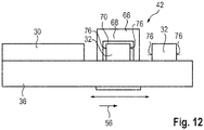
- FIG 11 is in a plan view and in figure 12 in a side view, a further embodiment of the production device 42 is shown in part, wherein the receiving station 44, the winding device 48 and the unwinding device 54, which are not shown, are not changed.
- the laser cutting group 58 also further includes the laser 60 and the optics 64, which are not shown, and by means of which the laser beam 62 is suitably guided.
- the cutting table 66 is also present, with the raw film 34 passing between the optics 64 and the cutting table 66 .
- the complete laser cutting group 58 is no longer stationary, as in the previous embodiments, but is designed to be movable, namely in the feed direction 56. While one of the connections 32 is being cut out by means of the laser cutting group 58, the laser cutting group 58 is in the feed direction 56 with the raw film 34 with moved. In this case, the laser cutting group 58 is moved at the feed rate, at least when the cutting out takes place. Therefore, the shape of the slit 70 of the cutting mask 68 exactly corresponds to the outer contour of one of the terminals 32, and the cutting point 78 is guided according to the path of the slit 70 during movement.
- the complete laser cutting group 58 is moved counter to the feed direction 56 to the original position, and as soon as another of the connections 32 is to be created, again in the feed direction 56, with the laser beam 62 again corresponding to the slot 70 is moved.
- the cutting point 78 is set as a function of the feed rate, with the entire laser cutting group 58 being moved at least partially for this purpose.
- the laser cutting assembly 58 is moved in the feed direction 56 at the feed rate.
- the cutting point 78 is set as a function of the feed rate, so that the production system 42 can be operated at different feed rates, with the course of the edges 76 always being perpendicular to the feed direction 56 and thus to the edge area 30 . It is thus also possible to use the part of the raw foil 34 that is processed by the laser cutting group 58 during the start-up of the production device 42 as a conductor foil 38 after the processing. Thus, a reject is reduced.
Landscapes
- Engineering & Computer Science (AREA)
- Physics & Mathematics (AREA)
- Optics & Photonics (AREA)
- Plasma & Fusion (AREA)
- Mechanical Engineering (AREA)
- Manufacturing & Machinery (AREA)
- Chemical & Material Sciences (AREA)
- Chemical Kinetics & Catalysis (AREA)
- Electrochemistry (AREA)
- General Chemical & Material Sciences (AREA)
- Battery Electrode And Active Subsutance (AREA)
Abstract
Die Erfindung betrifft ein Verfahren (40) zur Herstellung einer Ableiterfolie (38) für Batterien (14). Eine Rolle (46) mit einer metallischen Rohfolie (34) wird bereitgestellt. Während die Rolle (46) mit einer Vorschubgeschwindigkeit in eine Vorschubrichtung (56) kontinuierlich abgerollt wird, werden mittels einer Laserschneidgruppe (58) in einem sich entlang der Vorschubrichtung (56) erstreckenden Randbereich (30) der abgewickelten Rohfolie (34) Anschlüsse (32) ausgeschnitten. Die Erfindung betrifft ferner eine Fertigungsvorrichtung (42).The invention relates to a method (40) for producing a conductor foil (38) for batteries (14). A roll (46) of metallic green foil (34) is provided. While the roll (46) is continuously unwound at a feed rate in a feed direction (56), a laser cutting group (58) is used to cut connections (32) in an edge region (30) of the unwound raw film (34) extending along the feed direction (56). cut out. The invention also relates to a manufacturing device (42).
Description
Die Erfindung betrifft ein Verfahren zur Herstellung einer Ableiterfolie für Batterien sowie eine Fertigungsvorrichtung.The invention relates to a method for producing a conductor foil for batteries and a production device.
In zunehmendem Maße werden Kraftfahrzeuge zumindest teilweise mittels eines Elektromotors angetrieben, sodass diese als Elektrofahrzeug oder Hybridfahrzeug ausgestaltet sind. Zur Bestromung des Elektromotors wird üblicherweise eine Hochvoltbatterie herangezogen, die mehrere einzelne Batteriemodule umfasst. Die Batteriemodule sind meist zueinander baugleich sowie miteinander elektrisch in Reihe und/oder parallel geschaltet, sodass die an der Hochvoltbatterie anliegende elektrische Spannung einem Vielfachen der mittels jedes der Batteriemodule bereitgestellten elektrischen Spannung entspricht. Jedes Batteriemodul wiederum umfasst mehrere Batterien, die meist in einem gemeinsamen Gehäuse angeordnet sind, und die miteinander elektrisch in Reihe und/oder parallel geschaltet sind.Motor vehicles are increasingly being driven at least partially by means of an electric motor, so that they are designed as electric vehicles or hybrid vehicles. A high-voltage battery, which comprises a number of individual battery modules, is usually used to power the electric motor. The battery modules are usually structurally identical to one another and are electrically connected to one another in series and/or in parallel, so that the electrical voltage present at the high-voltage battery corresponds to a multiple of the electrical voltage provided by each of the battery modules. Each battery module in turn comprises a plurality of batteries which are usually arranged in a common housing and which are electrically connected to one another in series and/or in parallel.
Jede der Batterien wiederum umfasst üblicherweise mehrere Batteriezellen, die jeweils auch als galvanisches Element bezeichnet werden. Diese weisen jeweils zwei Elektroden, nämlich eine Anode und eine Kathode, sowie einen dazwischen angeordneten Separator als auch einen Elektrolyten mit freibeweglichen Ladungsträgern auf. Als ein derartiger Elektrolyt wird beispielsweise eine Flüssigkeit herangezogen. In einer Alternative ist die Batterie als Festkörperbatterie ausgestaltet, und der Elektrolyt liegt als Festkörper vor.Each of the batteries, in turn, usually includes a number of battery cells, each of which is also referred to as a galvanic element. These each have two electrodes, namely an anode and a cathode, as well as a separator arranged between them and an electrolyte with freely mobile charge carriers. A liquid, for example, is used as such an electrolyte. In an alternative, the battery is in the form of a solid-state battery and the electrolyte is in the form of a solid.
Die Anode und die Kathode, die die Elektroden der Batteriezelle bilden, umfassen üblicherweise einen Stromableiter auch lediglich als Ableiter oder Träger bezeichnet wird. An diesem ist üblicherweise ein Aktivmaterial befestigt, das ein Bestandteil einer auf den Träger aufgebrachten Schicht ist. Hierbei ist es möglich, dass in der Schicht bereits der Elektrolyt vorhanden ist, oder dieser wird nachträglich eingebracht. Zumindest jedoch ist das Aktivmaterial zur Aufnahme der Arbeitsionen, z.B. Lithium-Ionen, geeignet. Je nach Verwendung als Anode oder Kathode wird ein anderes Material für den Träger und eine unterschiedliche Art des Materials der Schicht verwendet.The anode and the cathode, which form the electrodes of the battery cell, usually include a current conductor, also referred to simply as a conductor or carrier. An active material, which is part of a layer applied to the carrier, is usually attached to this. It is possible that the electrolyte is already present in the layer, or that it is introduced later. However, the active material is at least suitable for absorbing the working ions, eg lithium ions. Depending on whether it is used as an anode or cathode, a different material is used for the support and a different type of material for the layer.
Die Ableiter werden üblicherweise aus einer Metallfolie erstellt, sodass eine Dicke der Elektroden vergleichsweise gering ist. Die Metallfolie liegt üblicherweise zunächst als Rohfolie in Rollenform vor. Auf diese wird die Schicht aufgetragen und anschließend ausgehärtet. Im Anschluss hieran erfolgt ein Ablängen von der Rollware, sodass die jeweilige Elektrode erstellt ist. Damit eine elektrische Kontaktierung der Elektrode vereinfacht ist, wird nicht auf die vollständige Fläche der Rohfolie die Schicht aufgetragen, sondern ein Randbereich wird frei von der Schicht belassen, sodass dort eine direkte elektrische Kontaktierung mit dem Ableiter ermöglicht ist. Hierfür ist lediglich ein vergleichsweise geringer Abschnitt des Randbereichs erforderlich, und der verbleibende Teil des Randbereichs wird nicht benötigt. Damit dieser Platz anderweitig genutzt werden kann, wird der Randbereich in diesem Teil meist ausgespart, wobei dies üblicherweise vor dem Aufbringen der Schicht erfolgt.The conductors are usually made from a metal foil, so that the thickness of the electrodes is comparatively small. The metal foil is usually initially in the form of a raw foil in the form of a roll. The layer is applied to this and then cured. The roll goods are then cut to length so that the respective electrode is created. In order to simplify electrical contacting of the electrode, the layer is not applied to the entire surface of the raw film, but an edge area is left free of the layer, so that direct electrical contacting with the arrester is made possible there. Only a comparatively small section of the edge area is required for this, and the remaining part of the edge area is not required. So that this space can be used for other purposes, the edge area in this part is usually cut out, this usually being done before the layer is applied.
Üblicherweise wird zum Aussparen zunächst die Rohfolie abgewickelt und zu einer Stanzmaschine geleitet. Mittels dieser erfolgt ein Stanzen des Randbereichs, sodass die Abschnitte als Anschlüsse stehen bleiben und die verbleibenden Teile abgetrennt werden. Nachfolgend wird die auf diese Weise bearbeitete Rohfolie erneut aufgewickelt und kann zwischengelagert werden. Auch ist ein direktes Weiterverarbeiten, insbesondere das Versehen mit der Schicht, ermöglicht.Usually, the raw film is first unwound and fed to a punching machine to make a cut-out. This is used to punch the edge area so that the sections remain as connections and the remaining parts are separated. The raw film processed in this way is then wound up again and can be temporarily stored. Direct further processing, in particular the provision of the layer, is also possible.
Zum Stanzen ist es erforderlich, dass der abgewickelte und zu stanzende Abschnitt der Rohfolie nicht bewegt wird. Somit wird zunächst der Abschnitt der Rolle abgewickelt und in die Stanzmaschine geführt. Im Anschluss wird die Rolle stillgesetzt und die Stanzmaschine betätigt. Nachfolgend wird dieser Stanzmaschine aus der Stanzmaschine entfernt, wofür die Rolle erneut abgewickelt und somit ein neuer Abschnitt der Rohfolie der Stanzmaschine zugeleitet wird. Folglich erfolgt ein getaktetes Bearbeiten der Rohfolie. Somit wirkt einerseits eine vergleichsweise hohe Belastung auf der Rohfolie. Andererseits ist aufgrund der Materialeigenschaften der Rohfolie eine maximale Beschleunigung und Abbremsung vorgegeben. Somit ist es nicht möglich, die Herstellungsgeschwindigkeit über ein bestimmtes Maß zu erhöhen.For punching it is necessary that the unwound section of the raw film to be punched is not moved. Thus, first the section of the roll is unwound and fed into the punching machine. The roll is then stopped and the punching machine is activated. This punching machine is then removed from the punching machine, for which purpose the roll is unwound again and a new section of the raw film is thus fed to the punching machine. Consequently, the raw film is processed in a cycled manner. Thus, on the one hand, a comparatively high load acts on the raw film. On the other hand, due to the material properties of the raw film, a maximum acceleration and deceleration is specified. Thus, it is not possible to increase the manufacturing speed beyond a certain level.
Der Erfindung liegt die Aufgabe zugrunde, ein besonders geeignetes Verfahren zur Herstellung einer Ableiterfolie für Batterien und eine besonders geeignete Fertigungsvorrichtung zur Herstellung einer Ableiterfolie anzugeben, wobei vorteilhafterweise eine Flexibilität erhöht und/oder ein Ausschuss verringert sind.The invention is based on the object of specifying a particularly suitable method for producing a collector foil for batteries and a particularly suitable production device for producing a collector foil, flexibility being advantageously increased and/or rejects being reduced.
Hinsichtlich des Verfahrens wird diese Aufgabe durch die Merkmale des Anspruchs 1 und hinsichtlich der Fertigungsvorrichtung durch die Merkmale des Anspruchs 7 erfindungsgemäß gelöst. Vorteilhafte Weiterbildungen und Ausgestaltungen sind Gegenstand der jeweiligen Unteransprüche.With regard to the method, this object is achieved according to the invention by the features of claim 1 and with regard to the production device by the features of claim 7 . Advantageous developments and refinements are the subject of the respective dependent claims.
Das Verfahren dient der Herstellung einer Ableiterfolie für Batterien. Zum Beispiel ist es dabei möglich, aus der Ableiterfolie lediglich einen einzigen Ableiter zu erstellen. Besonders bevorzugt ist es jedoch möglich, aus der Ableiterfolie mehrere Ableiter zu erstellen. Die erstellten Ableiter sind im bestimmungsgemäßen Zustand jeweils ein Bestandteil einer Elektrode der jeweiligen Batterie. Die mittels der Ableiterfolie erstellten Elektroden sind dabei beispielsweise Anoden oder Kathoden. Jede der Elektroden umfasst zweckmäßigerweise eine Schicht, die auf den jeweiligen Ableiter aufgetragen ist. Die Schicht weist insbesondere ein Aktivmaterial auf, das zur Aufnahme von Arbeitsionen, wie Lithium-Ionen, geeignet sowie vorgesehen und eingerichtet ist. Als Aktivmaterial wird beispielsweise ein Lithium-Metall-Oxid, wie Lithium-Cobalt(III)-Oxid (LiCoO2), NMC, NCA, LFP, GIC, LTO verwendet. Alternativ wird als Aktivmaterial NMC622 oder NMC811 herangezogen.The process is used to produce a conductor foil for batteries. For example, it is possible to create only a single conductor from the conductor foil. However, it is particularly preferably possible to create a number of conductors from the conductor foil. In the intended condition, the created arresters are each a component of an electrode of the respective battery. The electrodes created by means of the conductor foil are, for example, anodes or cathodes. Each of the electrodes expediently comprises a layer which is applied to the respective collector. The layer has, in particular, an active material that is suitable and provided and set up to absorb working ions, such as lithium ions. A lithium metal oxide, such as lithium cobalt(III) oxide (LiCoO2), NMC, NCA, LFP, GIC, LTO, for example, is used as the active material. Alternatively, NMC622 or NMC811 is used as the active material.
Beispielsweise werden für die jeweilige Batterie mehrere Elektroden übereinandergestapelt, wobei sich hierbei die Anoden und Kathoden abwechseln, und wobei zwischen den einzelnen Elektroden jeweils ein Separator angeordnet ist. Mit anderen Worten umfasst die Batterie somit einen Zellstapel. Alternativ hierzu wird die Ableiter Folie oder zumindest ein Teil hiervon aufgewickelt, und die Batterie umfasst eine sogenannte "Jelly Roll".For example, a plurality of electrodes are stacked one on top of the other for the respective battery, with the anodes and cathodes alternating in this case, and with a separator being arranged in each case between the individual electrodes. In other words, the battery thus includes a cell stack. As an alternative to this, the conductor foil or at least part of it is wound up and the battery comprises a so-called “jelly roll”.
Die erstellten Batterien sind im bestimmungsgemäßen Zustand vorzugsweise jeweils ein Bestandteil eines Kraftfahrzeugs. Hierfür sind die Batterien geeignet, insbesondere vorgesehen und eingerichtet. Im bestimmungsgemäßen Zustand sind die Batterien beispielsweise ein Bestandteil eines Energiespeichers des Kraftfahrzeugs, der mehrere derartige Batterien aufweist. Vorzugsweise sind hierbei die Batterien auf mehrere Batteriemodule aufgeteilt, die zueinander wiederum baugleich sind. Die Batterien sind insbesondere in einem Gehäuse des Energiespeichers bzw. des jeweiligen Batteriemoduls angeordnet und miteinander elektrisch parallel und/oder in Reihe geschaltet. Somit ist die an dem Energiespeicher/Batteriemodul anliegende elektrische Spannung ein Vielfaches der mittels jeder der Batterien bereitgestellten elektrischen Spannung. Das Gehäuse des Energiespeichers bzw. des jeweiligen Batteriemoduls ist bevorzugt aus einem Metall gefertigt, beispielsweise einem Stahl, wie einem Edelstahl, oder einer Aluminium-Legierung. Zu dessen Herstellung wird zum Beispiel ein Druckgussverfahren verwendet. Insbesondere ist das Gehäuse des Energiespeichers bzw. des jeweiligen Batteriemoduls verschlossen ausgestaltet. Zweckmäßigerweise ist in das Gehäuse des Energiespeichers bzw. des jeweiligen Batteriemoduls eine Schnittstelle eingebracht, die einen Anschluss des Energiespeichers/Batteriemoduls bildet. Die Schnittstelle ist dabei elektrisch mit den Batterien kontaktiert, sodass ein Einspeisen von elektrischer Energie und/oder eine Entnahme von elektrischer Energie aus den Batterien von außerhalb des Energiespeichers möglich ist, sofern an den Anschluss ein entsprechender Stecker gesteckt ist.In the intended state, the batteries produced are preferably a component part of a motor vehicle. The batteries are suitable for this, in particular provided and set up. In the intended state, the batteries are, for example, part of an energy store in the motor vehicle, which has a number of such batteries. In this case, the batteries are preferably divided among a number of battery modules, which in turn are structurally identical to one another. The batteries are arranged in particular in a housing of the energy store or of the respective battery module and are electrically connected to one another in parallel and/or in series. The electrical voltage applied to the energy store/battery module is therefore a multiple of the electrical voltage provided by each of the batteries. The housing of the energy store or of the respective battery module is preferably made of a metal, for example steel, such as stainless steel, or an aluminum alloy. A die-casting process, for example, is used to produce it. In particular, the housing of the energy store or of the respective battery module is designed to be closed. An interface is expediently introduced into the housing of the energy store or the respective battery module, which connects the Energy storage / battery module forms. The interface is in electrical contact with the batteries, so that it is possible to feed in electrical energy and/or to draw electrical energy from the batteries from outside the energy store, provided that a corresponding plug is plugged into the connection.
Das Kraftfahrzeug ist bevorzugt landgebunden und weist vorzugsweise eine Anzahl an Rädern auf, von denen zumindest eines, vorzugsweise mehrere oder alle, mittels eines Antriebs angetrieben sind. Geeigneterweise ist eines, vorzugsweise mehrere, der Räder steuerbar ausgestaltet. Somit ist es möglich, das Kraftfahrzeug unabhängig von einer bestimmten Fahrbahn, beispielsweise Schienen oder dergleichen, zu bewegen. Dabei ist es zweckmäßigerweise möglich, das Kraftfahrzeug im Wesentlichen beliebig auf einer Fahrbahn zu positionieren, die insbesondere aus einem Asphalt, einem Teer oder Beton gefertigt ist. Das Kraftfahrzeug ist beispielsweise ein Nutzkraftwagen, wie ein Lastkraftwagen (Lkw) oder ein Bus. Besonders bevorzugt jedoch ist das Kraftfahrzeug ein Personenkraftwagen (Pkw).The motor vehicle is preferably land-based and preferably has a number of wheels, of which at least one, preferably several or all, are driven by a drive. Suitably one, preferably several, of the wheels is designed to be steerable. It is thus possible to move the motor vehicle independently of a specific roadway, for example rails or the like. It is expediently possible to position the motor vehicle essentially anywhere on a roadway that is made of asphalt, tar or concrete in particular. The motor vehicle is, for example, a commercial vehicle, such as a truck (truck) or a bus. However, the motor vehicle is particularly preferably a passenger car.
Mittels des Antriebs erfolgt zweckmäßigerweise eine Fortbewegung des Kraftfahrzeugs. Zum Beispiel ist der Antrieb, insbesondere der Hauptantrieb, zumindest teilweise elektrisch ausgestaltet, und das Kraftfahrzeug ist beispielsweise ein Elektrofahrzeug. Der Elektromotor wird zum Beispiel mittels des Energiespeichers betrieben, der geeigneterweise als eine Hochvoltbatterie ausgestaltet ist. Mittels der Hochvoltbatterie wird zweckmäßigerweise eine elektrische Gleichspannung bereitgestellt, wobei die elektrische Spannung zum Beispiel zwischen 200 V und 800 V und beispielsweise im Wesentlichen 400 V beträgt. Vorzugsweise ist zwischen dem Energiespeicher und dem Elektromotor ein elektrischer Umrichter angeordnet, mittels dessen die Bestromung des Elektromotors eingestellt wird. In einer Alternative weist der Antrieb zusätzlich einen Verbrennungsmotor auf, sodass das Kraftfahrzeug als Hybrid-Kraftfahrzeug ausgestaltet ist. In einer Alternative wird mittels des Energiespeichers ein Niedervoltbordnetz des Kraftfahrzeugs gespeist, und mittels des Energiespeichers wird insbesondere eine elektrische Gleichspannung von 12 V, 24 V oder 48 V bereitgestellt.The motor vehicle is expediently moved by means of the drive. For example, the drive, in particular the main drive, is designed at least partially electrically, and the motor vehicle is an electric vehicle, for example. The electric motor is operated, for example, by means of the energy store, which is suitably designed as a high-voltage battery. An electrical DC voltage is expediently provided by means of the high-voltage battery, the electrical voltage being between 200 V and 800 V, for example, and essentially 400 V, for example. An electrical converter is preferably arranged between the energy store and the electric motor, by means of which the energization of the electric motor is adjusted. In an alternative, the drive also has an internal combustion engine, so that the motor vehicle is designed as a hybrid motor vehicle. In an alternative, a low-voltage electrical system of the motor vehicle is fed by means of the energy store, and by means of the energy store, in particular, an electrical DC voltage of 12 V, 24 V or 48 V is provided.
In einer weiteren Alternative ist die Batterie ein Bestandteil eines Flurförderfahrzeug, einer Industrieanlage, eines handgeführten Geräts, wie beispielsweise eines Werkzeugs, insbesondere eines Akkuschraubers. In einer weiteren Alternative ist die Batterie ein Bestandteil einer Energieversorgung und wird dort beispielsweise als sogenannte Pufferbatterie verwendet. In einer weiteren Alternative ist die Batterie ein Bestandteil eines tragbaren Geräts, beispielsweise eines tragbaren Mobiltelefons, oder eines sonstigen Wearables. Auch ist es möglich, eine derartige Batterie im Campingbereich, Modellbaubereich oder für sonstige Outdoor-Aktivitäten zu verwenden.In a further alternative, the battery is a component of an industrial truck, an industrial plant, a hand-held device, such as a tool, in particular a cordless screwdriver. In a further alternative, the battery is part of an energy supply and is used there, for example, as a so-called backup battery. In a further alternative, the battery is part of a portable device, for example a portable mobile phone, or another wearable. It is also possible such a Battery to be used in camping, model making or for other outdoor activities.
Das Verfahren sieht vor, dass zunächst eine Rolle mit einer metallischen Rohfolie bereitgestellt ist. Mit anderen Worten ist die Rohfolie zu der Rolle zusammengerollt. Die Rohfolie ist aus einem Metall erstellt, wobei das Metall auf die Art der Elektrode abgestimmt ist, die mittels des jeweiligen aus der Ableiterfolie erstellten Ableiters erstellt werden soll. So wird für eine Ableiterfolie, aus der Anoden erstellt werden sollen, beispielsweise eine Kupferfolie verwendet, und für Ableiter, mittels der Kathoden erstellt werden sollen, wird vorzugsweise eine Aluminiumfolie verwendet. Beispielsweise besteht die Rohfolie lediglich auf blankem Metall. Alternativ hierzu ist auf dem Metall bereits eine Beschichtung vorhanden, insbesondere eine Schicht. Diese ist beispielsweise lediglich auf einer Seite oder auf beiden Seiten des Metalls vorhanden. Die Schicht weist beispielsweise das jeweilige Aktivmaterial, einen Binder und/oder ein Leitadditiv auf, wie beispielsweise Leitruß oder Leitgraphit.The method provides that a roll with a metallic raw foil is initially provided. In other words, the raw film is rolled up into the roll. The raw foil is made of a metal, the metal being matched to the type of electrode that is to be created using the respective conductor made from the conductor foil. For example, a copper foil is used for a conductor foil from which anodes are to be produced, and an aluminum foil is preferably used for conductors which are to be used to produce cathodes. For example, the raw foil consists only of bare metal. As an alternative to this, a coating is already present on the metal, in particular a layer. This is present, for example, only on one side or on both sides of the metal. The layer has, for example, the respective active material, a binder and/or a conductive additive, such as conductive carbon black or conductive graphite.
Bei dem Verfahren wird die Rollen mit einer Vorschubgeschwindigkeit in eine Vorschubrichtung kontinuierlich abgerollt. Insbesondere ist hierbei die Vorschubrichtung senkrecht zur Achse, um die die Rohfolie aufgewickelt ist, und um die die Rolle zum Abrollen rotiert wird. Die Vorschubgeschwindigkeit ist beispielsweise konstant oder auf aktuelle Anforderungen angepasst. Insbesondere wird diese bei Beginn des Verfahrens zunächst erhöht, bis eine gewünschte Geschwindigkeit erreicht ist. Die Vorschubgeschwindigkeit korrespondiert zu einer Geschwindigkeit, mit der die Rolle abgerollt wird. Insbesondere wird der Teil der Rohfolie, der abgewickelt wird, einer Laserschneidgruppe zugeleitet.In the method, the rolls are continuously unrolled at a feed rate in a feed direction. In particular, the feed direction is perpendicular to the axis around which the raw film is wound and around which the roll is rotated for unwinding. The feed rate is, for example, constant or adapted to current requirements. In particular, this is initially increased at the beginning of the method until a desired speed is reached. The feed speed corresponds to a speed at which the roll is unwound. In particular, the part of the raw film that is unwound is fed to a laser cutting group.
Mittels der Laserschneidgruppe werden, während die Rolle abgerollt wird, in einem Randbereich der abgewickelten Rohfolie Anschlüsse ausgeschnitten. Die Anschlüsse, die mittels der Laserschneidgruppe ausgeschnitten werden, verbleiben an den restlichen Bestandteilen der Rohfolie, und die sich zwischen den Anschlüssen in Vorschubrichtung befindenden Bestandteile werden von dem Rest der Rohfolie abgetrennt. Insbesondere weisen die Anschlüsse einer rechteckförmige Form auf, und der Randbereich erstreckt sich entlang der vollständigen Vorschubrichtung. Zum Beispiel reicht der Randbereich von einer Kante der Rohfolie, die sich entlang der Vorschubrichtung erstreckt, zu einem Mittelbereich und entspricht zum Beispiel maximal 10 %, 5 % oder 2 % der Ausdehnung senkrecht zu der Kante.Connections are cut out in an edge area of the unwound raw film by means of the laser cutting group while the roll is being unwound. The leads cut out by the laser cutting group remain on the remaining components of the raw film, and the components located between the leads in the direction of feed are severed from the rest of the raw film. In particular, the terminals have a rectangular shape and the edge area extends along the full feed direction. For example, the edge area extends from an edge of the raw film, which extends along the feed direction, to a central area and corresponds, for example, to a maximum of 10%, 5% or 2% of the extension perpendicular to the edge.
Sofern die Rohfolie bereits mit der Schicht versehen ist, ist zweckmäßigerweise der Randbereich frei von der Schicht. Sofern die Schicht noch nicht vorhanden ist, wird geeigneterweise nachfolgend lediglich der Bereich beschichtet, der nicht mittels der Anschlüsse gebildet ist. Der Abstand der Anschlüsse zueinander in Vorschubrichtung, die mittels der Laserschneidgruppe ausgeschnitten werden, ist beispielsweise konstant. In diesem Fall werden anhand der Ableiterfolie zweckmäßigerweise mehrere gleichartige Ableiter erstellt, und die mittels der Ableiter erstellten Elektroden werden insbesondere übereinandergestapelt. Alternativ hierzu ändert sich der Abstand der Anschlüsse in Vorschubrichtung, und anhand der Ableiterfolie wird insbesondere eine Elektrode erstellt, die aufgewickelt ist, insbesondere zu einer sogenannten "Jelly Roll".If the raw film is already provided with the layer, the edge area is expediently free of the layer. If the layer does not already exist, it will suitably subsequently only the area not formed by means of the terminals is coated. The distance between the connections in the feed direction, which are cut out by means of the laser cutting group, is constant, for example. In this case, several conductors of the same type are expediently created using the conductor foil, and the electrodes created using the conductors are, in particular, stacked one on top of the other. As an alternative to this, the distance between the connections changes in the feed direction, and an electrode which is wound up, in particular to form what is known as a “jelly roll”, is produced on the basis of the conductor foil in particular.
Beispielsweise ist die Rohfolie, bei der die Anschlüsse ausgeschnitten sind, die Ableiterfolie, oder es sind weitere Arbeitsschritte zum vollständigen Erstellen der Ableiterfolie erforderlich, wie beispielsweise das Versehen mit der etwaigen Schicht. Zumindest jedoch ist es möglich, anhand der Ableiterfolie einen oder mehrere Ableiter für die Batterien zu erstellen.For example, the raw foil in which the terminals are cut out is the conductor foil, or further work steps are required to completely create the conductor foil, such as providing the eventual layer. However, it is at least possible to use the conductor foil to create one or more conductors for the batteries.
Da während des kontinuierlichen Abrollens der Rolle die Anschlüsse ausgeschnitten werden, ist ein Beschleunigen und Abbremsen der Rohfolie, was zu einer vergleichsweise hohen mechanischen Belastung der Rohfolie führen würde, nicht erforderlich. Somit ist eine Beschädigung der Rohfolie beim Herstellen der Ableiterfolie vermieden, weswegen ein Ausschuss verringert ist. Auch ist es möglich, die Vorschubgeschwindigkeit an bestimmte Anforderungen anzupassen und beispielsweise die Menge der erstellten Ableiterfolie auf die aktuellen Bedürfnisse anzupassen. Somit ist eine Flexibilität erhöht. Dabei ist es auch möglich, eine vergleichsweise hohe Vorschubgeschwindigkeit und somit eine vergleichsweise hohe Herstellungsgeschwindigkeit für die Ableiterfolie zu wählen, ohne dass mehrere Laserschneidgruppen erforderlich sind. Somit sind Herstellungskosten einer Fertigungsvorrichtung zur Herstellung der Ableiterfolie, die entsprechend des Verfahrens betrieben ist, verringert. Da zudem die Laserschneidgruppe vergleichsweise wenige bewegte Teile aufweist, ist die Anpassung der Vorschubgeschwindigkeit erleichtert.Since the connections are cut out during the continuous unwinding of the roll, it is not necessary to accelerate and decelerate the raw film, which would lead to a comparatively high mechanical load on the raw film. Damage to the raw foil during production of the conductor foil is thus avoided, which is why rejects are reduced. It is also possible to adapt the feed speed to specific requirements and, for example, to adapt the amount of collector foil produced to current needs. Flexibility is thus increased. In this case, it is also possible to select a comparatively high feed rate and thus a comparatively high production rate for the conductor foil, without the need for a plurality of laser cutting groups. Thus, manufacturing costs of a manufacturing device for manufacturing the conductor foil, which is operated according to the method, are reduced. In addition, since the laser cutting group has comparatively few moving parts, it is easier to adjust the feed rate.
Die Laserschneidgruppe weist vorzugsweise einen Laser auf, mittels dessen eine Optik bestrahlt ist. Mittels der Optik ist es zweckmäßigerweise möglich, und diese ist insbesondere hierfür vorgesehen und eingerichtet, den Laserstrahl, der mittels des Lasers erstellt wird, umzulenken. Geeigneterweise umfasst die Optik hierfür einen angetriebenen oder zumindest beweglichen Spiegel. Zweckmäßigerweise weist die Laserschneidgruppe zusätzlich einen Schneidtisch mit einer Schneidmaske auf. Insbesondere ist der Bereich der Rohfolie, der mittels der Laserschneidgruppe geschnitten werden soll, zwischen der Optik und dem Schneidetisch angeordnet. Die Schneidmaske ist insbesondere darauf angepasst, wie der Laserstrahl mittels der Optik geführt wird. Mittels der Schneidmaske wird zweckmäßigerweise zumindest teilweise die Form eines der Ableiter vorgegeben, und bei einem Durchdringen des Laserstrahls durch die Rohfolie trifft dieser auf einen bestimmten Teil der Schneidmaske trifft, bei dem ein Zurückstreuen zu der Rohfolie vermieden ist.The laser cutting group preferably has a laser, by means of which an optical system is irradiated. It is expediently possible by means of the optics, and this is provided and set up in particular for this purpose, to deflect the laser beam that is created by means of the laser. The optics suitably comprise a driven or at least movable mirror for this purpose. The laser cutting group expediently also has a cutting table with a cutting mask. In particular, the area of the raw film that is to be cut by means of the laser cutting group is arranged between the optics and the cutting table. The cutting mask is particularly adapted to how the laser beam is adjusted by means of the optics to be led. The cutting mask expediently at least partially defines the shape of one of the conductors, and when the laser beam penetrates through the raw film, it hits a specific part of the cutting mask where backscattering to the raw film is avoided.
Vorzugsweise wird ein Schneidpunkt der Laserschneidgruppe, also der Punkt, an dem mittels der Laserschneidgruppe in den Randbereich geschnitten wird, in Abhängigkeit der Vorschubgeschwindigkeit eingestellt. Somit ist es möglich, unterschiedliche Vorschubgeschwindigkeiten zu wählen, wobei stets die Anschlüsse wie gewünscht geschnitten werden. Daher ist ein Ausschuss reduziert. Hierbei ist es auch möglich, die Vorschubgeschwindigkeit zu variieren, und beispielsweise bei einem Anlauf, also bei einem Start des Abrollens der Rohfolie von der Rolle, bei der diese mit einer vergleichsweise geringen Geschwindigkeit bewegt wird, bereits die Anschlüsse entsprechend der jeweiligen Vorgabe auszuschneiden, ohne dass ein Ausschuss vorhanden ist. Beispielsweise wird dabei der Schneidpunkt der Laserschneidgruppe lediglich in Abhängigkeit der Vorschubgeschwindigkeit eingestellt oder bevorzugt auch in Abhängigkeit weiterer Parameter, wie bevorzugt der aktuellen Lage/Position der Laserschneidgruppe.A cutting point of the laser cutting group, ie the point at which the edge area is cut by means of the laser cutting group, is preferably set as a function of the feed rate. It is thus possible to select different feed speeds, while always cutting the connections as desired. Therefore, rejects are reduced. It is also possible to vary the feed speed and, for example, when starting up, i.e. when the raw film starts to unroll from the roll, in which it is moved at a comparatively low speed, to already cut out the connections according to the respective specification without that there is a committee. For example, the cutting point of the laser cutting group is set only as a function of the feed rate or preferably also as a function of other parameters, such as the current location/position of the laser cutting group.
In einer Ausführungsform werden senkrecht zur Vorschubrichtung verlaufende Kanten der Anschlüsse mittels Führens des Schneidpunkts unter einem Winkel schräg zur Vorschubrichtung erstellt, wobei der Schneidpunkt mit einer Schneidgeschwindigkeit bewegt wird. Hierbei wird beispielsweise eine senkrecht zur Vorschubrichtung verlaufende Komponente der Schneidgeschwindigkeit in Abhängigkeit der Vorschubgeschwindigkeit gewählt. Folglich wird die Bewegungsgeschwindigkeit des Schneidpunkts, also die Schneidgeschwindigkeit, in Abhängigkeit der Vorschubgeschwindigkeit gewählt und somit eingestellt. Folglich wird auch bei unterschiedlichen Vorschubgeschwindigkeiten stets eine senkrecht zur Vorschubrichtung verlaufende Kante in die Rohfolie geschnitten, sodass der Form der Anschlüsse im Wesentlichen unabhängig von der der Vorschubgeschwindigkeit ist. Geeigneterweise ist der Winkel, unter dem der Schneidpunkt geführt wird, konstant. Somit ist es möglich, stets die gleiche Schneidmaske heranzuziehen, weswegen Herstellungskosten verringert sind.In one embodiment, edges of the connections running perpendicularly to the feed direction are created by guiding the cutting point at an angle obliquely to the feed direction, with the cutting point being moved at a cutting speed. In this case, for example, a component of the cutting speed running perpendicularly to the feed direction is selected as a function of the feed rate. Consequently, the speed of movement of the cutting point, ie the cutting speed, is selected depending on the feed speed and is thus set. Consequently, even with different feed speeds, an edge running perpendicularly to the feed direction is always cut into the raw film, so that the shape of the connections is essentially independent of that of the feed speed. Suitably the angle at which the cutting point is guided is constant. Thus, it is possible to always use the same cutting mask, which is why manufacturing costs are reduced.
In einer Alternative hierzu wird beispielsweise der Winkel in Abhängigkeit der Vorschubgeschwindigkeit gewählt, wenn senkrecht zur Vorschubrichtung verlaufende Kanten erstellt werden sollen. Beispielsweise wird hierbei die Schneidgeschwindigkeit konstant gewählt, sodass eine Ansteuerung der etwaigen Optik vereinfacht ist. Insbesondere ist die Schneidmaske verstellbar ausgestaltet und weist beispielsweise einen Schlitz auf, der verstellt werden kann. Der Schlitz ist hierbei insbesondere entsprechend des Winkels verstellt.In an alternative to this, for example, the angle is selected as a function of the feed rate if edges running perpendicular to the feed direction are to be created. For example, the cutting speed is chosen to be constant, so that controlling any optics is simplified. In particular, the cutting mask is designed to be adjustable and has, for example, a slot that can be adjusted. In this case, the slot is adjusted in particular according to the angle.
In einer weiteren Alternative wird die Laserschneidgruppe während des Ausschneidens jedes der Anschlüsse in der Vorschubrichtung mit der Vorschubgeschwindigkeit bewegt, sodass keine Relativbewegung zwischen der Laserschneidgruppe und der Rohfolie erfolgt. Somit ist es möglich, die Laserschneidgruppe in gleicher Weise anzusteuern, wie wenn die Rohfolie stillgesetzt ist. Somit ist eine Ansteuerung der Laserschneidgruppe vereinfacht und intuitiver. Nachdem der jeweilige Anschluss ausgeschnitten ist, wird Laserschneidgruppe zweckmäßigerweise in die ursprüngliche Position bewegt, also entgegen der Vorschubrichtung. Sobald nachfolgend die Rohfolie derart abgewickelt wurde, dass sich eine Stelle, an der ein weiterer der Anschlüsse ausgeschnitten werden soll, in der Laserschneidgruppe befindet, wird diese erneut in die Vorschubrichtung mit der Vorschubgeschwindigkeit bewegt.In a further alternative, the laser cutting group is moved in the feed direction at the feed speed during the cutting out of each of the connections, so that there is no relative movement between the laser cutting group and the raw foil. It is thus possible to control the laser cutting group in the same way as when the raw film is stopped. Control of the laser cutting group is thus simplified and more intuitive. After the respective connection has been cut out, the laser cutting group is expediently moved to the original position, i.e. in the opposite direction to the feed direction. As soon as the raw film has subsequently been unwound in such a way that a point at which another of the connections is to be cut out is in the laser cutting group, it is moved again in the feed direction at the feed rate.
Vorzugsweise entspricht die Rohfolie, in die die Anschlüsse eingebracht sind, der Ableiterfolie. Beispielsweise wird der Teil der Rohfolie, der bereits die Anschlüsse aufweist, abgelängt, insbesondere sofern die mittels der Ableiter erstellten Elektroden lagenförmig übereinander gestapelt werden sollen. Mit anderen Worten erfolgt eine Vereinzelung der Ableiter aus der Rohfolie, die die Anschlüsse aufweist, und die insbesondere die Ableiterfolie bildet. Alternativ hierzu wird der Teil der Rohfolie, der bereits die Anschlüsse aufweist, erneut aufgerollt, sodass eine Lagerhaltung ermöglicht ist. Somit ist es möglich, mehrere Ableiterfolien vorzuproduzieren und diese bei Bedarf zur Herstellung der Batterien heranzuziehen.The raw foil into which the connections are introduced preferably corresponds to the conductor foil. For example, the part of the raw foil that already has the connections is cut to length, in particular if the electrodes created by means of the arresters are to be stacked in layers one on top of the other. In other words, the conductors are separated from the raw film which has the connections and which, in particular, forms the conductor film. As an alternative to this, the part of the raw foil that already has the connections is rolled up again, so that storage is possible. It is therefore possible to pre-produce several conductor foils and use them to manufacture the batteries if required.
Die Fertigungsvorrichtung dient der Herstellung einer Ableiterfolie und ist hierfür geeignet, insbesondere vorgesehen und eingerichtet. Insbesondere ist die Fertigungsvorrichtung derart betrieben, dass mittels dieser die Ableiterfolie oder zumindest ein Vorprodukt hiervon hergestellt wird. Die Fertigungsvorrichtung weist eine Aufnahmestation für eine Rolle mit einer metallischen Rohfolie auf. Zudem weist die Fertigungsvorrichtung eine Abwickelvorrichtung für die Rolle auf. Insbesondere weist die Abwickelvorrichtung einen Elektromotor oder einer sonstigen Antrieb auf, mittels dessen die Rolle angetrieben ist. Zudem weist die Fertigungsvorrichtung eine Laserschneidgruppe auf.The production device is used to produce a conductor foil and is suitable for this purpose, in particular provided and set up. In particular, the production device is operated in such a way that it is used to produce the conductor foil or at least a preliminary product thereof. The production device has a receiving station for a roll with a metallic raw foil. In addition, the manufacturing device has an unwinding device for the roll. In particular, the unwinding device has an electric motor or some other drive, by means of which the roll is driven. In addition, the production device has a laser cutting group.
Die Fertigungsvorrichtung ist gemäß einem Verfahren betrieben, bei dem eine Rolle mit einer metallischen Rohfolie bereitgestellt wird. Insbesondere wird hierfür die Rohfolie von der Aufnahmestation aufgenommen. Während die Rolle mit einer Vorschubgeschwindigkeit in eine Vorschubrichtung kontinuierlich abgerollt wird, wird mittels der Laserschneidgruppe in einem sich entlang der Vorschubrichtung erstreckenden Randbereich der abgewickelten Rohfolie Anschlüsse ausgeschnitten. Zum Abrollen wird zweckmäßigerweise die Abwickelvorrichtung verwendet. Insbesondere weist die Fertigungsvorrichtung eine Steuereinheit auf, die geeignet, insbesondere vorgesehen und eingerichtet ist, das Verfahren durchzuführen. Geeigneterweise wird die Fertigungsvorrichtung verwendet, um das Verfahren durchzuführen.The manufacturing apparatus is operated according to a method in which a roll of a metallic raw foil is provided. In particular, the raw film is picked up by the pick-up station for this purpose. While the roll is continuously unwound at a feed speed in a feed direction, connections are cut out by means of the laser cutting group in an edge region of the unwound raw foil extending along the feed direction. The unwinding device is expediently used for unwinding. In particular, the production device has a control unit that is suitable, in particular provided and set up, to carry out the method. Suitably the manufacturing device is used to carry out the method.
Geeigneterweise umfasst die Fertigungsvorrichtung zusätzlich eine Aufrollvorrichtung, sodass die bearbeitete Rohfolie, die insbesondere die Ableiterfolie bildet, also die die Rohfolie ist, aus der die Anschlüsse ausgeschnitten sind, aufgewickelt wird. Die Laserschneidgruppe umfasst zweckmäßigerweise einen Laser. Bei Betrieb des Lasers wird mittels dessen ein Laserstrahl erzeugt, der insbesondere auf eine Optik der Laserschneidgruppe gerichtet ist. Zweckmäßigerweise ist die Optik verstellbar ausgestaltet, sodass mittels der Optik der Laserstrahl geeignet geführt und/oder umgelenkt wird. Zudem weist die Laserschneidgruppe zweckmäßigerweise einen Schneidetisch mit einer Schneidmaske auf. Die Schneidmaske weist dabei beispielsweise einen Schlitz, mehrere Schlitze oder sonstige Aussparungen auf, wobei der zuschneidende Gegenstand, insbesondere die Rohfolie, sich bei Betrieb der Laserschneidgruppe zwischen der Optik und dem Schneidetisch befindet. Die Aussparungen in dem Schneidetisch sind hierbei derart, dass bei Durchdringen des zuschneiden Gegenstand, also der Rohfolie, mittels des Laserstrahls, dieser auf die Schlitze trifft, sodass ein unkontrolliertes Zurückstreuen auf die Rohfolie vermieden ist.Suitably, the production device additionally includes a winding device, so that the processed raw foil, which in particular forms the conductor foil, ie which is the raw foil from which the connections are cut, is wound up. The laser cutting group expediently comprises a laser. During operation of the laser, a laser beam is generated by means of it, which is directed in particular to an optical system of the laser cutting group. The optics are expediently designed to be adjustable, so that the laser beam is suitably guided and/or deflected by means of the optics. In addition, the laser cutting group expediently has a cutting table with a cutting mask. The cutting mask has, for example, a slit, a plurality of slits or other recesses, with the object to be cut, in particular the raw film, being located between the optics and the cutting table when the laser cutting group is in operation. The recesses in the cutting table are such that when the laser beam penetrates the object to be cut, i.e. the raw film, it hits the slits, so that uncontrolled backscattering onto the raw film is avoided.
Die Erfindung betrifft daher auch die Verwendung der Fertigungsvorrichtung zur Durchführung des Verfahrens und auch eine gemäß dem Verfahren und/oder mittels der Fertigungsvorrichtung hergestellte Ableiterfolie sowie eine daraus erstellte Batterie.The invention therefore also relates to the use of the production device for carrying out the method and also to a conductor foil produced according to the method and/or by means of the production device and a battery produced therefrom.
Die im Zusammenhang mit dem Verfahren beschriebenen Vorteile und Weiterbildungen sind sinngemäß auch auf die Fertigungsvorrichtung /die Verwendung/ die Ableiterfolie /die Batterie und untereinander zu übertragen und umgekehrt.The advantages and developments described in connection with the method can also be transferred to the manufacturing device/the use/the conductor foil/the battery and to each other and vice versa.
Nachfolgend werden Ausführungsbeispiele der Erfindung anhand einer Zeichnung näher erläutert. Darin zeigen:
- Fig. 1
- schematisch vereinfacht ein Kraftfahrzeug, das eine Hochvoltbatterie mit mehreren baugleichen Batterien aufweist,
- Fig. 2
- in einer Schnittdarstellung schematisch eine der Batterien, die zwei Ableiter aufweist, die aus einer Ableiterfolie erstellt sind
- Fig. 3
- in einer Draufsicht ausschnittsweise eine Rohfolie,
- Fig. 4
- gemäß
Fig. 3 eine aus der Rohfolie erstellte Ableiterfolie, - Fig. 5
- ein Verfahren zur Herstellung einer Ableiterfolie für Batterien,
- Fig. 6
- in einer Draufsicht eine eine Schneidmaske aufweisende Fertigungsvorrichtung zur Herstellung einer Ableiterfolie,
- Fig. 7
- die Schneidmaske in einer Frontalansicht,
- Fig. 8 - 10
- eine weitere Variante der Schneidmaske in unterschiedlichen Betriebsstellungen,
- Fig. 11
- gemäß
Fig. 6 ausschnittsweise eine Alternative der Fertigungsvorrichtung, und - Fig. 12
- in einer Frontalansicht die Fertigungsvorrichtung gemäß
Fig. 11 .
- 1
- schematically simplified a motor vehicle that has a high-voltage battery with several identical batteries,
- 2
- a schematic sectional view of one of the batteries, which has two conductors that are created from a conductor foil
- 3
- in a top view, a cutout of a raw film,
- 4
- according to
3 a conductor foil created from the raw foil, - figure 5
- a method for producing a conductor foil for batteries,
- 6
- in a top view, a manufacturing device having a cutting mask for manufacturing a conductor foil,
- 7
- the cutting mask in a frontal view,
- Figures 8 - 10
- another variant of the cutting mask in different operating positions,
- 11
- according to
6 a detail of an alternative manufacturing device, and - 12
- in a front view the manufacturing device according to FIG
11 .
Einander entsprechende Teile sind in allen Figuren mit den gleichen Bezugszeichen versehen.Corresponding parts are provided with the same reference symbols in all figures.
In
Jedes der Batteriemodule wiederum umfasst mehrere Batterien 14, von denen hier zwei dargestellt sind. Die Batterien 14 jedes Batteriemoduls sind elektrisch miteinander zum Teil parallel und anderenfalls elektrisch in Reihe geschaltet, sodass die mittels jedes Batteriemoduls bereitgestellte elektrische Spannung einem Vielfachen der mittels einer der Batterien 14 bereitgestellten elektrischen Spannung beträgt.Each of the battery modules in turn includes
In
Die Anode 18 und die Kathode 20 weisen jeweils einen Ableiter 24 auf, der auch als Träger bezeichnet wird, und der jeweils eine Metallfolie ist. Im Fall der Anode 18 ist der Ableiter 24 eine Kupferfolie, und im Fall der Kathode 20 ist der Ableiter 24 eine Aluminiumfolie. Die Ableiter 24 sind zumindest auf der dem Separator 22 zugewandten Seite jeweils mit einer Schicht 26 versehen, die ein Aktivmaterial, wie NMC, und einen Binder sowie ein Leitadditiv aufweist. Im Fall der Anode 18 ist das Leitadditiv zum Beispiel Graphit und im Fall der Kathode 20 Leitruß.The
Hierbei ist nicht jeweils der vollständige Ableiter 24 mit der Schicht 26 versehen, sondern lediglich ein Hauptkörper 28, und ein sich jeweils in einem Randbereich 30 befindender Anschluss 32 ist frei von der Schicht 26. Die Größe des Hauptkörpers 28 und somit auch die Größe der Schicht 26 entspricht dabei der Größe des Separators 22. Im Montagezustand sind an den Anschlüssen 32 weitere Bestandteile elektrisch angebunden, beispielsweise die Anschlüsse 32 der weiteren Batteriezellen 16 oder Anschlüsse der Batterie 14, insbesondere über sogenannte Stromschienen.In this case, not the
In
Aus der Rohfolie 34 wird eine Ableiterfolie 38 erstellt, die in
In
Die Fertigungsvorrichtung 42 weist zudem eine Aufnahmestation 44 für eine Rolle 46 auf, zu der die metallische Rohfolie 34 aufgerollt ist. Auch weist die Fertigungsvorrichtung 42 eine Aufrollvorrichtung 48 mit einer weiteren Rolle 50 auf. Sowohl die Aufrollvorrichtung 48 als auch die Aufnahmestation 44 weisen jeweils einen Antrieb 52 auf, mittels derer die Rolle 46 bzw. die weitere Rolle 50 angetrieben sind. Die Antriebe 52 sind Bestandteile einer Abwickelvorrichtung für die Rolle 46, und bei Betrieb der Antrieb 52 wird die Rolle 46 ab und folglich die Rohfolie 46 in eine Vorschubrichtung 56 abgewickelt und auf die weitere Rolle 50 aufgewickelt, die sich in Vorschubrichtung 56 hinter der Rolle 46 befindet.The
Zwischen der Aufnahmestation 44 und der Aufrollvorrichtung 48 ist eine Laserschneidgruppe 58 angeordnet, die einen Laser 60 aufweist. Bei Betrieb wird mittels des Lasers 60 ein Laserstrahl 62 erstellt, der auf eine Optik 64 der Laserschneidgruppe 58 gerichtet ist. Die Optik 64 weist einen nicht näher dargestellten Spiegel auf, der beweglich gelagert sowie angetrieben ist. Dabei ist es möglich, mittels der Einstellung der Optik 64 den Verlauf des Laserstrahls 62 zu verändern. Der Laserstrahl 62 ist mittels der Optik 64 auf einen Schneidtisch 66 gerichtet, der eine Schneidmaske 68 aufweist. Hierbei wird, wenn die Rohfolie 34 von der Rolle 46 abgewickelt und in Richtung der Aufrollvorrichtung 48 in der Vorschubrichtung 56 bewegt wird, diese zwischen der Optik 64 und dem Schneidtisch 66 hindurchbewegt. Die Schneidmaske 68 bildet zumindest teilweise die der Rohfolie 34 zugewandte Begrenzung des Schneidtischs 66. Die Schneidmaske 68 ist in
Das Verfahren 40 sieht vor, dass in einem ersten Arbeitsschritt 72 die Rolle 46 mit der metallischen Rohfolie 34 bereitgestellt wird. Hierfür wird die Rolle 46 in die Aufnahmestation 44 eingesetzt. In einem nachfolgenden zweiten Arbeitsschritt 74 wird die Rolle 46 mit einer Vorschubgeschwindigkeit in die Vorschubrichtung 56 kontinuierlich abgerollt und somit durch die Laserschneidgruppe 58 hindurchgeführt. Hierbei erstreckt sich der Randbereich 30 entlang der Vorschubrichtung 56.The
In einem sich anschließenden dritten Arbeitsschritt 75 werden, während die Rolle 46 kontinuierlich mit der Vorschubgeschwindigkeit abgerollt wird, also der abgerollte Teil der Rohfolie 34 mit der Vorschubgeschwindigkeit in die Vorschubrichtung 56 bewegt wird, mittels der Laserschneidgruppe 58 in den Randbereich 30 der abgewickelten Rohfolie 34 die Anschlüsse 32 ausgeschnitten. Die Anschlüsse 32 weisen jeweils senkrecht zum Verlauf des Randbereichs 30 verlaufende Kanten 76 auf, die somit auch senkrecht zu der Vorschubrichtung 56 sind. Zum Schneiden dieser Kanten 76 der Anschlüsse 32, die senkrecht zur Vorschubrichtung 56 verlaufen, wird ein Schneidpunkt 78, also der Punkt, an dem der Laserstrahl 62 auf die Rohfolie 34 trifft, unter einem Winkel schräg zur Vorschubrichtung 56 geführt.In a subsequent
Das Führen des Schneidpunkts 78 erfolgt mit einer Schneidgeschwindigkeit, die in Abhängigkeit der Vorschubgeschwindigkeit gewählt wird. Dabei wird die senkrecht zur Vorschubrichtung 56 verlaufende Komponente der Schneidgeschwindigkeit sowie auch die parallel zur Vorschubrichtung 56 verlaufende Komponente der Schneidgeschwindigkeit in Abhängigkeit der Vorschubgeschwindigkeit gewählt. Dabei wird der Schneidpunkt 78 stets derart bewegt, dass dieser stets auf den mittels der Rohfolie 34 abgedeckten dreiecksförmigen Schlitz 70 trifft. Mit anderen Worten wird der Schneidpunkt 78 entlang der Dreiecksform des in
Nachdem die Rohfolie 34 die Laserschneidgruppe 58 in Vorschubrichtung 56 passiert hat, weist diese die Anschlüsse 32 auf, und die Ableiterfolie 38 ist erstellt. Diese wird in einem vierten Arbeitsschritt 79 auf die Aufrollvorrichtung 48 zur weiteren Rolle 50 aufgewickelt, sodass der Teil der Rohfolie 34, der die bereits erstellten Anschlüsse 32 aufweist, erneut aufgewickelt wird. Dabei wird aufgrund des Antriebs der weiteren Rolle 50 auch die Rohfolie 34 von der Rolle 46 abgewickelt.After the
In den
In
Falls jedoch, wie von dem Verfahren 40 abgedeckt, die Rohfolie 34 während des Schneidens kontinuierlich abgerollt wird, erfolgt eine Bewegung der Rohfolie 54 bezüglich des Schneidtisch 66. Um die senkrecht verlaufenden Kanten 76 zu erstellen, wird daher der Schneidpunkt 78 unter einem Winkel schräg zur Vorschubrichtung 56 geführt, wobei stets die gleiche Schneidgeschwindigkeit gewählt wird. Hierbei wird der Schneidpunkt 78 oberhalb des Schlitzes 70 bewegt, sodass auch der der Winkel zwischen dem Schlitz 70 und der Vorschubrichtung 56 in Abhängigkeit der Vorschubgeschwindigkeit gewählt ist. So wird bei einer vergleichsweise hohen Vorschubgeschwindigkeit, wie in
In
Die vollständige Laserschneidgruppe 58 ist jedoch nicht mehr ortsfest, wie bei den vorherigen Ausführungsformen, sondern beweglich ausgestaltet, nämlich in der Vorschubrichtung 56. Während einer der Anschlüsse 32 mittels der Laserschneidgruppe 58 ausgeschnitten wird, wird die Laserschneidgruppe 58 in der Vorschubrichtung 56 mit der Rohfolie 34 mit bewegt. Dabei wird die Laserschneidgruppe 58 mit der Vorschubgeschwindigkeit bewegt, zumindest wenn das Ausschneiden erfolgt. Daher entspricht die Form des Schlitzes 70 der Schneidmaske 68 genau dem Außenumriss eines der Anschlüsse 32, und der Schneidpunkt 78 wird während des Bewegens entsprechend des Verlaufs des Schlitzes 70 geführt. Sobald der jeweilige Anschluss 32 ausgeschnitten ist, wird die vollständige Laserschneidgruppe 58 entgegen der Vorschubrichtung 56 in die ursprüngliche Position bewegt, und, sobald ein weiterer der Anschlüsse 32 erstellt werden soll, erneut in die Vorschubrichtung 56, wobei der Laserstrahl 62 erneut entsprechend des Schlitzes 70 bewegt wird. Somit wird auch hier der Schneidpunkt 78 in Abhängigkeit der Vorschubgeschwindigkeit eingestellt, wobei hierfür zumindest teilweise die vollständige Laserschneidgruppe 58 bewegt wird. Zusammenfassend wird somit die Laserschneidgruppe 58 während des Ausschneidens jedes der Anschlüsse 32 in der Vorschubrichtung 56 mit der Vorschubgeschwindigkeit bewegt.However, the complete
Bei sämtlichen Varianten wird der Schneidpunkt 78 in Abhängigkeit der Vorschubgeschwindigkeit eingestellt, sodass die Fertigungsanlage 42 mit unterschiedlichen Vorschubgeschwindigkeiten betrieben werden kann, wobei der Verlauf der Kanten 76 stets senkrecht zur Vorschubrichtung 56 und somit zum Randbereich 30 ist. Somit ist es auch möglich, den Teil der Rohfolie 34, der während des Anfahrens der Fertigungsvorrichtung 42 mittels der Laserschneidgruppe 58 bearbeitet wird, als Ableiterfolie 38 nach dem Bearbeiten heranzuziehen. Somit ist ein Ausschuss verringert.In all variants, the
Die Erfindung ist nicht auf die vorstehend beschriebenen Ausführungsbeispiele beschränkt. Vielmehr können auch andere Varianten der Erfindung von dem Fachmann hieraus abgeleitet werden, ohne den Gegenstand der Erfindung zu verlassen. Insbesondere sind ferner alle im Zusammenhang mit den einzelnen Ausführungsbeispielen beschriebene Einzelmerkmale auch auf andere Weise miteinander kombinierbar, ohne den Gegenstand der Erfindung zu verlassen.The invention is not limited to the exemplary embodiments described above. On the contrary, other variants of the invention can also be derived from this by a person skilled in the art without departing from the subject matter of the invention. In particular, all of the individual features described in connection with the individual exemplary embodiments can also be combined with one another in other ways without departing from the subject matter of the invention.
- 22
- Kraftfahrzeugmotor vehicle
- 44
- Radwheel
- 66
- Antriebdrive
- 88th
- Energiespeicherenergy storage
- 1010
- Schnittstelleinterface
- 1212
- GehäuseHousing
- 1414
- Batteriebattery
- 1616
- Batteriezellebattery cell
- 1818
- Anodeanode
- 2020
- Kathodecathode
- 2222
- Separatorseparator
- 2424
- Ableiterarrester
- 2626
- Schichtlayer
- 2828
- Hauptkörpermain body
- 3030
- Randbereichedge area
- 3232
- Anschlussconnection
- 3434
- Rohfolieraw film
- 3636
- Hauptbereichmain area
- 3838
- Ableiterfolieconductor foil
- 4040
- Verfahrenprocedure
- 4242
- Fertigungsvorrichtungmanufacturing device
- 4444
- Aufnahmestationadmission station
- 4646
- Rollerole
- 4848
- Aufrollvorrichtungretractor
- 5050
- weitere Rolleanother role
- 5252
- Antriebdrive
- 5454
- Abwickelvorrichtungunwinding device
- 5656
- Vorschubrichtungfeed direction
- 5858
- Laserschneidgruppelaser cutting group
- 6060
- Laserlaser
- 6262
- Laserstrahllaser beam
- 6464
- Optikoptics
- 6666
- Schneidtischcutting table
- 6868
- Schneidmaskecutting mask
- 7070
- Schlitzslot
- 7272
- erster Arbeitsschrittfirst step
- 7474
- zweiter Arbeitsschrittsecond step
- 7575
- dritter Arbeitsschrittthird step
- 7676
- Kanteedge
- 7878
- Schneidpunktcutting point
- 7979
- vierter Arbeitsschrittfourth step
- 8080
- Hebellever
Claims (7)
Applications Claiming Priority (1)
| Application Number | Priority Date | Filing Date | Title |
|---|---|---|---|
| DE102021202644.3A DE102021202644A1 (en) | 2021-03-18 | 2021-03-18 | Process for producing a conductor foil for batteries |
Publications (1)
| Publication Number | Publication Date |
|---|---|
| EP4060772A1 true EP4060772A1 (en) | 2022-09-21 |
Family
ID=80780709
Family Applications (1)
| Application Number | Title | Priority Date | Filing Date |
|---|---|---|---|
| EP22162131.1A Pending EP4060772A1 (en) | 2021-03-18 | 2022-03-15 | Method for producing a conductor foil for batteries |
Country Status (4)
| Country | Link |
|---|---|
| US (1) | US20220297238A1 (en) |
| EP (1) | EP4060772A1 (en) |
| CN (1) | CN115148412A (en) |
| DE (1) | DE102021202644A1 (en) |
Citations (3)
| Publication number | Priority date | Publication date | Assignee | Title |
|---|---|---|---|---|
| DE102013203810A1 (en) * | 2013-03-06 | 2014-09-11 | Thyssenkrupp System Engineering Gmbh | Method and apparatus for cutting an electrode tape |
| US20180079035A1 (en) * | 2016-01-06 | 2018-03-22 | O.M.C. Co., Ltd. | Method for producing electrode sheet with tab and apparatus therefor |
| EP3415265A1 (en) * | 2017-06-12 | 2018-12-19 | Robert Bosch GmbH | Method and device for high-throughput cutting of a ribbon-type substrate, particularly for an electrode of a battery, into separated pieces |
-
2021
- 2021-03-18 DE DE102021202644.3A patent/DE102021202644A1/en active Pending
-
2022
- 2022-03-15 EP EP22162131.1A patent/EP4060772A1/en active Pending
- 2022-03-17 US US17/697,460 patent/US20220297238A1/en active Pending
- 2022-03-18 CN CN202210268524.3A patent/CN115148412A/en active Pending
Patent Citations (3)
| Publication number | Priority date | Publication date | Assignee | Title |
|---|---|---|---|---|
| DE102013203810A1 (en) * | 2013-03-06 | 2014-09-11 | Thyssenkrupp System Engineering Gmbh | Method and apparatus for cutting an electrode tape |
| US20180079035A1 (en) * | 2016-01-06 | 2018-03-22 | O.M.C. Co., Ltd. | Method for producing electrode sheet with tab and apparatus therefor |
| EP3415265A1 (en) * | 2017-06-12 | 2018-12-19 | Robert Bosch GmbH | Method and device for high-throughput cutting of a ribbon-type substrate, particularly for an electrode of a battery, into separated pieces |
Also Published As
| Publication number | Publication date |
|---|---|
| DE102021202644A1 (en) | 2022-09-22 |
| CN115148412A (en) | 2022-10-04 |
| US20220297238A1 (en) | 2022-09-22 |
Similar Documents
| Publication | Publication Date | Title |
|---|---|---|
| EP2705556B1 (en) | Method and device for producing electrode coils | |
| EP2647070A1 (en) | Method and system for cutting sheet-like or plate-like objects | |
| DE102017216138A1 (en) | Method for producing an electrode stack for a battery cell and battery cell | |
| EP3878030B1 (en) | Method of production of a cathode device, method of production of an electrode composite and battery | |
| WO2012065767A1 (en) | Production method for electrodes | |
| EP3758104A1 (en) | Method for producing battery electrodes | |
| WO2019076592A1 (en) | Method for producing a battery cell and battery cell | |
| DE102017216193A1 (en) | Process for the production of electrodes | |
| EP3968426A2 (en) | Method and device for producing a cell stack for battery cells | |
| EP3968427A2 (en) | Method and device for producing a cell stack for battery cells | |
| EP2764561A1 (en) | Method and system for cutting sheet-shaped or plate-shaped objects | |
| DE102012005229B4 (en) | Method for producing a battery cell and battery cell | |
| WO2019052815A1 (en) | Stacking device for multilayer, flat electrode stacks | |
| EP4060772A1 (en) | Method for producing a conductor foil for batteries | |
| WO2019052813A1 (en) | Method for producing an electrode stack for a battery cell, and battery cell | |
| DE102012213111B4 (en) | Method and device for the efficient production of film stacks for forming a lithium-ion battery cell | |
| DE102017216151A1 (en) | Workpiece carrier for transporting a multilayer electrode stack | |
| DE102020213941A1 (en) | Process for manufacturing an electrode of a battery | |
| DE102017216188A1 (en) | Method for producing an electrode stack for a battery cell and battery cell | |
| DE102017216131A1 (en) | Method for producing an electrode stack for a battery cell and battery cell | |
| DE102017207766A1 (en) | Method for producing an electrode stack for a battery cell and battery cell | |
| EP3968425A2 (en) | Method and device for producing a cell stack for battery cells | |
| EP4060779A2 (en) | Production device for batteries | |
| EP4068411A2 (en) | Method for manufacturing an electrode of a battery | |
| WO2023025440A1 (en) | Process for manufacturing a stack of electrode sheets, and cutting device, spacing element and cross-cutting device therefor |
Legal Events
| Date | Code | Title | Description |
|---|---|---|---|
| PUAI | Public reference made under article 153(3) epc to a published international application that has entered the european phase |
Free format text: ORIGINAL CODE: 0009012 |
|
| STAA | Information on the status of an ep patent application or granted ep patent |
Free format text: STATUS: THE APPLICATION HAS BEEN PUBLISHED |
|
| AK | Designated contracting states |
Kind code of ref document: A1 Designated state(s): AL AT BE BG CH CY CZ DE DK EE ES FI FR GB GR HR HU IE IS IT LI LT LU LV MC MK MT NL NO PL PT RO RS SE SI SK SM TR |
|
| STAA | Information on the status of an ep patent application or granted ep patent |
Free format text: STATUS: REQUEST FOR EXAMINATION WAS MADE |
|
| 17P | Request for examination filed |
Effective date: 20230321 |
|
| RBV | Designated contracting states (corrected) |
Designated state(s): AL AT BE BG CH CY CZ DE DK EE ES FI FR GB GR HR HU IE IS IT LI LT LU LV MC MK MT NL NO PL PT RO RS SE SI SK SM TR |
|
| GRAP | Despatch of communication of intention to grant a patent |
Free format text: ORIGINAL CODE: EPIDOSNIGR1 |
|
| STAA | Information on the status of an ep patent application or granted ep patent |
Free format text: STATUS: GRANT OF PATENT IS INTENDED |
|
| INTG | Intention to grant announced |
Effective date: 20240129 |
|
| GRAS | Grant fee paid |
Free format text: ORIGINAL CODE: EPIDOSNIGR3 |
|
| GRAA | (expected) grant |
Free format text: ORIGINAL CODE: 0009210 |
|
| STAA | Information on the status of an ep patent application or granted ep patent |
Free format text: STATUS: THE PATENT HAS BEEN GRANTED |