EP4060635A1 - Money handling machine - Google Patents
Money handling machine Download PDFInfo
- Publication number
- EP4060635A1 EP4060635A1 EP22162085.9A EP22162085A EP4060635A1 EP 4060635 A1 EP4060635 A1 EP 4060635A1 EP 22162085 A EP22162085 A EP 22162085A EP 4060635 A1 EP4060635 A1 EP 4060635A1
- Authority
- EP
- European Patent Office
- Prior art keywords
- money
- unit
- withdrawal
- handling machine
- withdrawal unit
- Prior art date
- Legal status (The legal status is an assumption and is not a legal conclusion. Google has not performed a legal analysis and makes no representation as to the accuracy of the status listed.)
- Granted
Links
Images




Classifications
-
- G—PHYSICS
- G07—CHECKING-DEVICES
- G07D—HANDLING OF COINS OR VALUABLE PAPERS, e.g. TESTING, SORTING BY DENOMINATIONS, COUNTING, DISPENSING, CHANGING OR DEPOSITING
- G07D11/00—Devices accepting coins; Devices accepting, dispensing, sorting or counting valuable papers
- G07D11/10—Mechanical details
- G07D11/12—Containers for valuable papers
- G07D11/125—Secure containers
-
- G—PHYSICS
- G07—CHECKING-DEVICES
- G07D—HANDLING OF COINS OR VALUABLE PAPERS, e.g. TESTING, SORTING BY DENOMINATIONS, COUNTING, DISPENSING, CHANGING OR DEPOSITING
- G07D11/00—Devices accepting coins; Devices accepting, dispensing, sorting or counting valuable papers
- G07D11/10—Mechanical details
- G07D11/14—Inlet or outlet ports
-
- G—PHYSICS
- G07—CHECKING-DEVICES
- G07D—HANDLING OF COINS OR VALUABLE PAPERS, e.g. TESTING, SORTING BY DENOMINATIONS, COUNTING, DISPENSING, CHANGING OR DEPOSITING
- G07D11/00—Devices accepting coins; Devices accepting, dispensing, sorting or counting valuable papers
- G07D11/10—Mechanical details
- G07D11/16—Handling of valuable papers
-
- G—PHYSICS
- G07—CHECKING-DEVICES
- G07D—HANDLING OF COINS OR VALUABLE PAPERS, e.g. TESTING, SORTING BY DENOMINATIONS, COUNTING, DISPENSING, CHANGING OR DEPOSITING
- G07D11/00—Devices accepting coins; Devices accepting, dispensing, sorting or counting valuable papers
- G07D11/20—Controlling or monitoring the operation of devices; Data handling
- G07D11/22—Means for sensing or detection
-
- G—PHYSICS
- G07—CHECKING-DEVICES
- G07D—HANDLING OF COINS OR VALUABLE PAPERS, e.g. TESTING, SORTING BY DENOMINATIONS, COUNTING, DISPENSING, CHANGING OR DEPOSITING
- G07D7/00—Testing specially adapted to determine the identity or genuineness of valuable papers or for segregating those which are unacceptable, e.g. banknotes that are alien to a currency
- G07D7/004—Testing specially adapted to determine the identity or genuineness of valuable papers or for segregating those which are unacceptable, e.g. banknotes that are alien to a currency using digital security elements, e.g. information coded on a magnetic thread or strip
- G07D7/0047—Testing specially adapted to determine the identity or genuineness of valuable papers or for segregating those which are unacceptable, e.g. banknotes that are alien to a currency using digital security elements, e.g. information coded on a magnetic thread or strip using checkcodes, e.g. coded numbers derived from serial number and denomination
-
- G—PHYSICS
- G07—CHECKING-DEVICES
- G07D—HANDLING OF COINS OR VALUABLE PAPERS, e.g. TESTING, SORTING BY DENOMINATIONS, COUNTING, DISPENSING, CHANGING OR DEPOSITING
- G07D2211/00—Paper-money handling devices
Definitions
- the technique disclosed here relates to a money handling machine.
- Patent Document 1 describes an automatic correcting method of automated equipment such as an automated trading machine in, for example, a financial institution.
- money is delivered from a safe by the automated equipment based on a payment telegram from a center to a customer, is counted up while discriminating whether the money is real or not, and then is discharged to a receiving part. If money remains in the receiving part after a lapse of a given time, the money is taken in and rediscriminated and counted. The amount counted before discharge is compared with the rediscriminated amount.
- both the amounts coincide with each other money taken from the receiving part is stored in the safe, and a correction telegram is sent to the center and the account balance of the customer in the center is returned to the balance before payment. If both the amounts do not coincide with each other, the money taken from the receiving part is collected to a non-managed money collection unit for collecting money out of management in the automated equipment.
- the money handling machine disclosed here includes: a withdrawal unit configured to receive money therein and allow the money to be removed from the inside of the withdrawal unit; a detector configured to detect a removal action associated with removal of the money; and a controller configured to switch a process on money remaining in the withdrawal unit based on a result of detection by the detector.
- the money handling machine may include a storage unit configured to store the money, and the withdrawal unit may receive money delivered from the storage unit.
- the withdrawal unit is used as a destination of withdrawn money in the withdrawal process.
- the withdrawal unit may be used as a rejection unit that receives money as a target to be rejected. For example, rejection money determined not to be received in a deposit process or a replacement process is transported to the rejection unit.
- the money handling machine may include a transport unit configured to transport money.
- the controller may control the transport unit to switch a destination to which money remaining in the withdrawal unit is delivered.
- money delivered from the storage unit is transported to the withdrawal unit by the transport unit.
- the controller may perform a first process of controlling an operation of the money handling machine such that the money remaining in the withdrawal unit is transported into the money handling machine in a case where the detector does not detect the removal action.
- the money remaining in the withdrawal unit may be transported to the storage unit.
- the controller may be configured to perform a second process on the money remaining in the withdrawal unit in a case where the detector detects the removal action, and the second process is different from the first process.
- the result of detection by the detector may be a detection result before a lapse of a predetermined time from when money delivered from the storage unit is received by the withdrawal unit.
- the controller may be configured to perform the first process in the case where the detector does not detect the removal action before a lapse of a predetermined time from when money delivered from the storage unit is received by the withdrawal unit.
- the controller may be configured to perform the first process in the case where the detector does not detect the removal action by the time when a predetermined time elapses from the time when money delivered from the storage unit is received by the withdrawal unit.
- the money handling machine may include a holder configured to hold the money.
- the holder is a structure different from the storage unit.
- the controller may control an operation of the money handling machine such that money remaining in the withdrawal unit is transported to the holder.
- the holder may store only the money remaining in the withdrawal unit.
- the money handling machine may include a recognition unit configured to recognize the money.
- the controller may switch a process on the money remaining in the withdrawal unit depending on a result of recognition by the recognition unit, in addition to the detection result by the detector. In the second process, the controller may switch the process on money remaining in the withdrawal unit depending on a recognition result by the recognition unit.
- the money handling machine may include a holder configured to hold the money, and the controller may perform control in the second process such that money remaining in the withdrawal unit is finally transported to one of the holder or the storage unit depending on a recognition result by the recognition unit.
- the recognition result may include at least one of the number of the money or a type of the money.
- the recognition result may include recognition information for recognizing the money.
- the recognition information may be a serial number of money.
- the recognition result may include a first recognition result that is a result of recognition by the recognition unit performed on money delivered from the storage unit and received by the withdrawal unit.
- the recognition result may include a second recognition result that is a result of recognition by the recognition unit performed on the money remaining in the withdrawal unit.
- the controller may switch a process on the money remaining in the withdrawal unit, depending on one or both of the first recognition result and the second recognition result. For example, the controller compares the first recognition result and the second recognition result with each other to thereby switch a process on the money remaining in the withdrawal unit.
- the controller may control an operation of the money handling machine in the second process such that the money remaining in the withdrawal unit is transported to the holder in a case where the first recognition result and the second recognition result do not coincide with each other.
- the controller may control an operation of the money handling machine in the second process such that the money remaining in the withdrawal unit is transported to the storage unit in a case where the first recognition result and the second recognition result do not coincide with each other.
- the money handling machine may include a temporary storage unit configured to temporarily store money.
- the controller may control an operation of the money handling machine such that the money remaining in the withdrawal unit is delivered from the withdrawal unit, transported to the recognition unit, and then stored in the temporary storage unit and may acquire the second recognition result in the second process.
- the controller may control an operation of the money handling machine in the second process such that the money stored in the temporary storage unit is transported to the holder in a case where the first recognition result and the second recognition result do not coincide with each other, and the money stored in the temporary storage unit is transported to the storage unit in a case where the first recognition result and the second recognition result coincide with each other.
- the detector may be a sensor.
- the detector may be an optical sensor.
- the detector may be an image sensor.
- the removal action may include movement money removed from the withdrawal unit.
- the movement of money may be movement of money from inside of the withdrawal unit to outside of the withdrawal unit.
- the removal action may include movement of an object entering the withdrawal unit.
- the object may be a hand of a person who is removing money.
- the removal action may include a person in front of the money handling machine.
- the movement of a person may be movement of a person who is removing money in front of the money handling machine.
- the detector may detect the removal action and whether the money is present in the withdrawal unit or not.
- FIG. 1 illustrates an example configuration of a money handling machine 1 according to a first embodiment.
- the money handling machine 1 includes a storage unit 11, a withdrawal unit 12, a holder 13, a transport unit 14, a detector 20, and a controller 25.
- the storage unit 11 stores money.
- the withdrawal unit 12 can receive money delivered from the storage unit 11 therein.
- the withdrawal unit 12 is configured to allow the money to be removed from the inside of the withdrawal unit 12.
- the holder 13 holds money.
- the transport unit 14 transports money among the storage unit 11, the withdrawal unit 12, and the holder 13.
- the detector 20 detects an action associated with removal of money from the withdrawal unit 12.
- the action associated with removal of money from the withdrawal unit 12 will be hereinafter referred to as a "removal action.”
- the controller 25 switches a process on money remaining in the withdrawal unit 12, depending on a result of detection by the detector 20.
- the money transport process is a process for transporting money remaining in the withdrawal unit 12.
- the money transport process is carried out in a case where money remains in the withdrawal unit 12 after a lapse of a predetermined time from when money delivered from the storage unit 11 is received by the withdrawal unit 12.
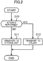
- the controller 25 determines whether a removal action is performed or not.
- the controller 25 measures an elapsed time from when money delivered from the storage unit 11 is received by the withdrawal unit 12. If the detector 20 detects the removal action before a lapse of a predetermined time from when money delivered from the storage unit 11 is received by the withdrawal unit 12, the controller 25 determines that the removal action is performed. If the detector 20 does not detect the removal action before a lapse of the predetermined time from when money delivered from the storage unit 11 is received by the withdrawal unit 12, the controller 25 determines that the removal action is not performed.
- step S12 is performed, and otherwise, step S11 is performed.
- the controller 25 performs a first process.
- the controller 25 controls an operation of the money handling machine 1 such that money remaining in the withdrawal unit 12 is transported to the storage unit 11.
- the controller 25 performs a second process different from the first process.
- the controller 25 controls an operation of the money handling machine 1 such that money remaining in the withdrawal unit 12 is transported to the holder 13.
- the controller 25 switches the process on the money remaining in the withdrawal unit 12, depending on a result of detection by the detector 20 configured to detect a removal action that is an action associated with money removal from the withdrawal unit 12. Specifically, the controller 25 performs the first process of controlling an operation of the money handling machine 1 such that money remaining in the withdrawal unit 12 is transported to the storage unit 11 in a case where the detector 20 does not detect a removal action, and performs the second process different from the first process on money remaining in the withdrawal unit 12 in a case where the detector 20 detects a removal action.
- the controller 25 controls an operation of the money handling machine 1 in the second process such that money remaining in the withdrawal unit 12 is transported to the holder 13.
- the controller 25 controls an operation of the money handling machine 1 in the second process such that money remaining in the withdrawal unit 12 is transported to the holder 13.
- the money remaining in the withdrawal unit 12 can be returned without any process. Accordingly, when an operator (e.g., a customer of a bank) who left money in the withdrawal unit 12 requests a return of "money remaining in the withdrawal unit 12," the money remaining in the withdrawal unit 12 can be appropriately returned.
- an operator e.g., a customer of a bank
- the removal action may include movement of money removed from the withdrawal unit 12.
- the detector 20 may detect movement of money removed from the withdrawal unit 12. In the case of removing money from the withdrawal unit 12, the money moves from the inside of the withdrawal unit 12 to the outside of the withdrawal unit 12. Thus, based on the movement of money removed from the withdrawal unit 12, it is confirmed that there is a possibility that part of money received by the withdrawal unit 12 has been removed from the withdrawal unit 12.
- the removal action may include movement of an object entering the withdrawal unit 12.
- the detector 20 may detect movement of an object entering the withdrawal unit 12. In the case of removing money from the withdrawal unit 12, to remove the money from the withdrawal unit 12, an object (e.g., a hand of a person who is removing money) enters the withdrawal unit 12. Thus, based on movement of the object entering the withdrawal unit 12, it is confirmed that there is a possibility that part of money received by the withdrawal unit 12 has been removed from the withdrawal unit 12.
- the removal action may include movement of a person in front of the money handling machine 1.
- the detector 20 may detect movement of a person in front of the money handling machine 1. In the case of removing money from the withdrawal unit 12, there is movement of a person who is to remove money in front of the money handling machine 1. Thus, based on the movement of a person in front of the money handling machine 1, it is confirmed that there is a possibility that part of money received by the withdrawal unit 12 has been removed from the withdrawal unit 12.
- the detector 20 may be configured to detect an action associated with money removal from the withdrawal unit 12 and whether the money is present in the withdrawal unit 12 or not. With this configuration, the number of components of the money handling machine 1 can be reduced, as compared to a case where a detector for detecting an action associated with money removal from the withdrawal unit 12 and a detector for detecting whether the money is present in the withdrawal unit 12 or not are provided separately.
- FIG. 3 illustrates an example configuration of a money handling machine 1 according to a second embodiment.
- the money handling machine 1 according to the second embodiment includes a recognition unit 15 and a temporary storage unit 16, in addition to the configuration of the money handling machine 1 according to the first embodiment illustrated in FIG. 1 .
- the transport unit 14 according to the second embodiment transports money among the storage unit 11, the withdrawal unit 12, the holder 13, and the temporary storage unit 16.
- the other part of the configuration of the money handling machine 1 according to the second embodiment is similar to the configuration of the money handling machine 1 according to the first embodiment.
- the recognition unit 15 recognizes money. Specifically, the recognition unit 15 recognizes, for example, serial numbers of money.
- the temporary storage unit 16 stores money.
- the temporary storage unit 16 temporarily stores money.
- money delivered from the storage unit 11 and received by the withdrawal unit 12 is recognized by the recognition unit 15.
- the controller 25 controls an operation of the money handling machine 1 such that money delivered from the storage unit 11 is recognized by the recognition unit 15 and then transported to the withdrawal unit 12. Then, the controller 25 acquires a result of recognition by the recognition unit 15 performed on money delivered from the storage unit 11 and received by the withdrawal unit 12.
- the controller 25 a result of recognition by the recognition unit 15 performed on money delivered from the storage unit 11 and received by the withdrawal unit 12 will be referred to as a "first recognition result.”
- the first recognition result includes, for example, serial numbers of money.
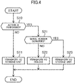
- steps S21 through S23 are performed instead of step S12 shown in FIG. 2 .
- the money transport process according to the second embodiment is different in the second process from the money transport process of the first embodiment.
- the controller 25 controls an operation of the money handling machine 1 such that money remaining in the withdrawal unit 12 is recognized by the recognition unit 15.
- the controller 25 controls an operation of the money handling machine 1 such that money delivered from the withdrawal unit 12 is recognized by the recognition unit 15 and then transported to the temporary storage unit 16.
- the controller 25 acquires a result of recognition by the recognition unit 15 performed on money remaining in the withdrawal unit 12.
- a result of recognition by the recognition unit 15 performed on money remaining in the withdrawal unit 12 will be referred to as a "second recognition result.”
- the second recognition result includes, for example, serial numbers of money.
- the controller 25 determines whether serial numbers of money shown in the first recognition result coincide with serial numbers of money shown in the second recognition result. Specifically, if all the serial numbers of money shown in the first recognition result coincide with all the serial numbers of money shown in the second recognition result in a one-to-one correspondence, the controller 25 determines that the serial numbers of money shown in the first recognition result coincide with the serial numbers of money shown in the second recognition result.
- step S23 is performed, and otherwise, step S22 is performed.
- the controller 25 controls an operation of the money handling machine 1 such that money remaining in the withdrawal unit 12 is transported to the holder 13.
- the controller 25 controls an operation of the money handling machine 1 such that money delivered from the temporary storage unit 16 is transported to the holder 13.
- the controller 25 controls an operation of the money handling machine 1 such that money remaining in the withdrawal unit 12 is transported to the storage unit 11.
- the controller 25 controls an operation of the money handling machine 1 such that money delivered from the temporary storage unit 16 is transported to the storage unit 11.
- the controller 25 controls an operation of the money handling machine 1 in the second process such that if the serial numbers of money shown in the first recognition result that is a result of recognition by the recognition unit 15 performed on money delivered from the storage unit 11 and received by the withdrawal unit 12 do not coincide with the serial numbers of money shown in the second recognition result that is a result of recognition by the recognition unit 15 performed on money remaining in the withdrawal unit 12, money remaining in the withdrawal unit 12 is transported to the holder 13.
- the controller 25 controls an operation of the money handling machine 1 such that if the serial numbers of money shown in the first recognition result coincide with the serial numbers of money shown in the second recognition result, money remaining in the withdrawal unit 12 is transported to the storage unit 11.
- FIG. 5 illustrates an example configuration of a money handling machine 1 according to a third embodiment.
- the money handling machine 1 according to the third embodiment is an example configuration of the money handling machines 1 according to the first and second embodiments.
- Directions (front, rear, up, and down) used herein correspond to directions when the money handling machine 1 placed on a horizontal plane is seen from the front.
- the front side of the money handling machine 1 is a side in which a deposit unit 31 and a withdrawal unit 32 are formed, and a rear side of the money handling machine 1 is a side opposite to the side in which the deposit unit 31 and the withdrawal unit 32 are formed.
- the money handling machine 1 constitutes a banknote processing machine for processing banknotes.
- the money handling machine 1 including a processor 30, a safe 40, and a transport unit 50.
- the money handling machine 1 performs various processes including a deposit process and a withdrawal process.
- the money handling machine 1 is installed in a financial institution such as a bank.
- the transport unit 50 is an example of the transport units 14 of the first and second embodiments.
- the processor 30 constitutes an upper portion of the money handling machine 1.
- the processor 30 includes a processing casing 30a.
- the processing casing 30a houses the deposit unit 31, the withdrawal unit 32, a rejection unit 33, a temporary storage unit 34, a retraction unit 35, and a recognition unit 36.
- the withdrawal unit 32 is an example of the withdrawal units 12 of the first and second embodiments.
- the temporary storage unit 34 is an example of the temporary storage unit 16 of the second embodiment.
- the retraction unit 35 is an example of the holders 13 of the first and second embodiments.
- the recognition unit 36 is an example of the recognition unit 15 of the second embodiment.
- the deposit unit 31 receives banknotes.
- the deposit unit 31 is disposed in an upper front portion of the processor 30.
- the deposit unit 31 has a deposit port that is open upward. An operator places banknotes in the deposit unit 31 through the deposit port.
- the deposit unit 31 can hold a stack of banknotes.
- the deposit unit 31 includes a feed mechanism that feeds banknotes in the deposit unit 31 to a processing-side transport unit 51 one by one.
- the withdrawal unit 32 feeds out banknotes.
- the withdrawal unit 32 is disposed forward of the deposit unit 31 in the upper front portion of the processor 30.
- the withdrawal unit 32 can hold a stack of banknotes.
- the withdrawal unit 32 has a withdrawal port 32a that is open upward. The operator can take out banknotes accumulated in the withdrawal unit 32 through the withdrawal port 32a by hand.
- the withdrawal unit 32 may include a shutter for opening and closing the withdrawal port 32a.
- the withdrawal unit 32 includes a feed in/out mechanism 32b.
- the feed in/out mechanism 32b receives banknotes from the processing-side transport unit 51 into the withdrawal unit 32 one by one.
- the feed in/out mechanism 32b feeds banknotes from the inside of the withdrawal unit 32 to the processing-side transport unit 51 one by one.
- the rejection unit 33 accumulates banknotes as a target to be rejected.
- the rejection unit 33 is disposed below the withdrawal unit 32 in a front portion of the processor 30.
- the rejection unit 33 can hold a stack of banknotes.
- the rejection unit 33 has a reject port that is open forward.
- the rejection unit 33 includes a shutter for opening and closing the reject port. When the shutter is opened, the operator can remove banknotes accumulated in the rejection unit 33 through the reject port by hand.
- the rejection unit 33 includes a feed in/out mechanism.
- the feed in/out mechanism receives banknotes from the processing-side transport unit 51 into the rejection unit 33 one by one.
- the feed in/out mechanism feeds banknotes from the inside of the rejection unit 33 to the processing-side transport unit 51 one by one.
- the temporary storage unit 34 stores banknotes.
- the temporary storage unit 34 feeds banknotes stored therein.
- the temporary storage unit 34 is disposed below the rejection unit 33 in a front portion of the processor 30.
- the configuration of the temporary storage unit 34 can employ a known configuration of a storage unit that stores and feeds banknotes.
- the temporary storage unit 34 is a tape-type storage unit.
- the tape-type storage unit stores banknotes by winding banknotes around a drum together with a tape.
- the temporary storage unit 34 may be a stack-type storage unit.
- the stack-type storage unit stores a stack of banknotes.
- the retraction unit 35 stores banknotes.
- the configuration of the retraction unit 35 can employ a known configuration of a storage unit that stores banknotes.
- the retraction unit 35 has a retraction port communicating with the inside of the retraction unit 35.
- the retraction unit 35 includes a shutter for opening and closing the retraction port. When the shutter is opened, the operator can remove banknotes accumulated in the retraction unit 35 through the retraction port by hand.
- the shutter of the retraction unit 35 may be configured to be opened only by an operator having predetermined authority (e.g., bank clerk).
- the recognition unit 36 recognizes banknotes. Specifically, the recognition unit 36 is provided in the processing-side transport unit 51 described later, and performs recognition on banknotes transported by the processing-side transport unit 51. In the recognition, the recognition unit 36 recognizes denomination, fitness, new or old, authenticity, transport state, and serial numbers of banknotes, for example.
- the recognition unit 36 includes sensors such as a line sensor, a magnetic sensor, and an image sensor, a processor, and a memory that stores programs and data for operating the processor. A result of recognition of banknotes by the recognition unit 36 is transmitted to the controller 25.
- the safe 40 includes a safe casing 40a.
- the safe casing 40a stores first through fifth storage units 41 through 45.
- the first through fifth storage units 41 through 45 are an example of the storage units 11 of the first and second embodiments.
- a security level of the safe casing 40a is higher than a security level of the processing casing 10a.
- the safe casing 40a is formed of a metal plate having a predetermined thickness or more, and protects, for example, the first through fifth storage units 41 through 45 at a security level of a predetermined level or more.
- the safe casing 40a includes a door configured to be opened and closed, and an electronic lock is attached to the door.
- the operator e.g., bank clerk
- the operator can access the first through fifth storage units 41 through 45 disposed inside the safe casing 40a.
- Each of the first through fifth storage units 41 through 45 stores banknotes. Each of the first through fifth storage units 41 through 45 feeds stored banknotes.
- the first through fifth storage units 41 through 45 are arranged in the front-rear direction.
- the configuration of each of the first through fifth storage units 41 through 45 can employ a known configuration of a storage unit that stores and feeds banknotes.
- the first through fifth storage units 41 through 45 are stack-type storage units.
- the first storage unit 41 includes a first storage region 41a and a second storage region 41b that are independent of each other.
- the first storage unit 41 stores and feeds banknotes in the first storage region 41a, and stores and feeds banknotes in the second storage region 41b.
- the second storage unit 42 includes a first storage region 42a and a second storage region 42b that are independent of each other.
- the second storage unit 42 stores and feeds banknotes in the first storage region 42a, and stores and feeds banknotes in the second storage region 42b.
- the transport unit 50 transports banknotes in the money handling machine 1.
- the transport unit 50 includes the processing-side transport unit 51, a first safe-side transport unit 52, and a second safe-side transport unit 53.
- the processing-side transport unit 51 is housed in the processing casing 30a.
- the processing-side transport unit 51 transports banknotes in the processor 30.
- the first safe-side transport unit 52 and the second safe-side transport unit 53 are housed in the safe casing 40a.
- the first safe-side transport unit 52 and the second safe-side transport unit 53 transport banknotes in the safe 40.
- the processing-side transport unit 51, the first safe-side transport unit 52, and the second safe-side transport unit 53 include transport paths.
- the transport paths include, for example, a transport mechanism for transporting banknotes, a guide member for guiding banknotes under transport, a branch mechanism for switching a transport direction of banknotes, and a driving mechanism for driving the transport mechanism and the branch mechanism.
- Examples of the transport mechanism include a roller and a belt.
- Examples of the branch mechanism include a branch pawl provided at a branch portion of the transport path.
- Examples of the driving mechanism include a motor and a gear.
- the processing-side transport unit 51 includes a ring-shaped path 510 and first through eighth transport paths 511 through 518.
- the ring-shaped path 510 is formed in a ring shape.
- the ring-shaped path 510 can transport banknotes both clockwise and counterclockwise in FIG. 5 .
- the first transport path 511 connects the ring-shaped path 510 to the deposit unit 31.
- the first transport path 511 transports banknotes between the ring-shaped path 510 and the deposit unit 31.
- the second transport path 512 connects the ring-shaped path 510 to the withdrawal unit 32.
- the second transport path 512 transports banknotes between the ring-shaped path 510 and the withdrawal unit 32.
- the third transport path 513 connects the ring-shaped path 510 to the rej ection unit 33.
- the third transport path 513 transports banknotes between the ring-shaped path 510 and the rejection unit 33.
- the third transport path 513 is partially shared by the second transport path 512.
- the fourth transport path 514 connects the ring-shaped path 510 to the temporary storage unit 34.
- the fourth transport path 514 conveys banknotes between the ring-shaped path 510 and the temporary storage unit 34.
- the fifth transport path 515 connects the ring-shaped path 510 to the retraction unit 35.
- the fifth transport path 515 transports banknotes between the ring-shaped path 510 and the retraction unit 35.
- the sixth transport path 516 connects the ring-shaped path 510 to a first transport path 521 of the first safe-side transport unit 52.
- the sixth transport path 516 transports banknotes between the ring-shaped path 510 and the first transport path 521 of the first safe-side transport unit 52.
- the seventh transport path 517 connects the ring-shaped path 510 to a second transport path 522 of the first safe-side transport unit 52.
- the seventh transport path 517 conveys banknotes between the ring-shaped path 510 and the second transport path 522 of the first safe-side transport unit 52.
- the eighth transport path 518 connects the ring-shaped path 510 to a third transport path 523 of the first safe-side transport unit 52.
- the eighth transport path 518 transports banknotes between the ring-shaped path 510 and the third transport path 523 of the first safe-side transport unit 52.
- the first safe-side transport unit 52 includes the first transport path 521, the second transport path 522, and the third transport path 523.
- the first transport path 521 connects the sixth transport path 516 of the processing-side transport unit 51 to the first storage region 41a of the first storage unit 41.
- the first transport path 521 transports banknotes between the sixth transport path 516 of the processing-side transport unit 51 and the first storage region 41a of the first storage unit 41.
- the second transport path 522 connects the sixth transport path 516 of the processing-side transport unit 51 to a first transport path 531 of the second safe-side transport unit 53 described later.
- the second transport path 522 transports banknotes between the sixth transport path 516 of the processing-side transport unit 51 and the first transport path 531 of the second safe-side transport unit 53.
- the third transport path 523 transports banknotes among the eighth transport path 518 of the processing-side transport unit 51, the first storage region 42a of the second storage unit 42, and the third through fifth storage units 43 through 45.
- the third transport path 523 includes a main path 524 and first through fourth branch paths 525 through 528.
- the main path 524 is connected to the eighth transport path 518 of the processing-side transport unit 51.
- the first branch path 525 connects the main path 524 to the first storage region 42a of the second storage unit 42.
- the second branch path 526 connects the main path 524 to the third storage unit 43.
- the third branch path 527 connects the main path 524 to the fourth storage unit 44.
- the fourth branch path 528 connects the main path 524 to the fifth storage unit 45.
- the second safe-side transport unit 53 includes the first transport path 531, a second transport path 532, and a third transport path 533.
- the first transport path 531 is connected to the second transport path 522 of the first safe-side transport unit 52.
- the second transport path 532 connects the first transport path 531 to the second storage region 41b of the first storage unit 41.
- the second transport path 532 transports banknotes between the first transport path 531 and the second storage region 41b of the first storage unit 41.
- the third transport path 533 connects the first transport path 531 to the second storage region 42b of the second storage unit 42.
- the third transport path 533 transports banknotes between the first transport path 531 and the second storage region 42b of the second storage unit 42.
- the money handling machine 1 includes various sensors such as a passage sensor for detecting passage of a banknote. Information obtained by these sensors is transmitted to the controller 25.
- the money handling machine 1 includes a first detector 21 and a second detector 22.
- the first detector 21 and the second detector 22 are an example of the detectors 20 of the first and second embodiments.
- the first detector 21 detects an action associated with removal of a banknote from the withdrawal unit 32.
- the first detector 21 detects movement of a banknote removed from the withdrawal unit 32.
- the first detector 21 also detects movement of an object entering the withdrawal unit 32.
- the first detector 21 includes a transmitter that transmits light and a receiver that receives light from the transmitter.
- the transmitter and the receiver are disposed such that when an object (specifically a hand of a person) enters the withdrawal unit 32 and removes a banknote from the withdrawal unit 32, light emitted from the transmitter toward the receiver is blocked by the banknote or the object
- the first detector 21 detects "movement of a banknote removed from the withdrawal unit 32" or "movement of the object entering the withdrawal unit 32" by blocking of light emitted from the transmitter toward the receiver.
- the second detector 22 detects whether a banknote is present in the withdrawal unit 32 or not.
- the second detector 22 includes a transmitter that transmits light and a receiver that receives light from the transmitter.
- the transmitter and the receiver are disposed such that in a case where the banknote is present in the withdrawal unit 32, light emitted from the transmitter toward the receiver is blocked by the banknote.
- the second detector 22 detects the presence of a banknote in the withdrawal unit 32 by blocking of light emitted from the transmitter toward the receiver.
- the money handling machine 1 includes an operation unit 26, a memory unit 27, and a communicator 28.
- the operation unit 26 receives a manipulation by an operator and outputs a signal in response to the manipulation. This configuration enables the operator to manipulate the operation unit 26 and input information and an instruction to the money handling machine 1.
- the memory unit 27 stores various types of information.
- the memory unit 27 stores, for example, information on an inventory of banknotes in the money handling machine 1, and information for use in control of components of the money handling machine 1.
- Examples of the information for use in control of components of the money handling machine 1 include values detected by sensors and thresholds for use in control of the components.
- the memory unit 27 may be an external storage disposed outside the controller 25.
- the communicator 28 is provided to allow the controller 25 to perform wired communication or wireless communication with external equipment.
- the external equipment include a tablet, a smartphone, and a management computer.
- the controller 25 of the third embodiment is connected to components of the money handling machine 1.
- the controller 25 can communicate with external equipment via the communicator 28
- the controller 25 controls components of the money handling machine 1 to control an operation of the money handling machine 1 based on a manipulation input to the operation unit 26, signals and information sent from components of the money handling machine 1 (including sensors provided in the components) and external equipment, for example.
- the controller 25 includes a processor, and a memory that stores programs and data for operating the processor. Control and determination by the controller 25 are performed by execution of a program by the processor.
- the program and data for operating the processor may be stored in the memory unit 27.
- a withdrawal process, a withdrawal banknote transport process, a withdrawal fraud determination process, a deposit process, a deposit banknote transport process, and a deposit fraud determination process are performed.
- the withdrawal process is a process for withdrawing banknotes from the money handling machine 1.
- the controller 25 controls an operation of the money handling machine 1 to perform a withdrawal process.
- banknotes delivered from a storage unit as a target of the withdrawal process in the first through fifth storage units 41 through 45 are transported to the recognition unit 36 via the first safe-side transport unit 52 and the processing-side transport unit 51, and recognized by the recognition unit 36. If the banknotes recognized by the recognition unit 36 are a target to be rejected, the banknotes are transported to the temporary storage unit 34. On the other hand, if the banknotes recognized by the recognition unit 36 are not a target to be rejected, the banknotes are transported to the withdrawal unit 32.
- the controller 25 acquires a result of recognition by the recognition unit 36 performed on banknotes delivered from the storage unit as a target of the withdrawal process and received by the withdrawal unit 32.
- a result of recognition by the recognition unit 36 performed on banknotes delivered from the storage unit as a target of the withdrawal process and received by the withdrawal unit 32 will be hereinafter referred as a "withdrawal recognition result.”
- the withdrawal recognition result includes serial numbers of banknotes and a total amount of banknotes.
- the withdrawal recognition result is an example of the first recognition result of the second embodiment.
- the withdrawal banknote transport process is performed in a case where banknotes remain in the withdrawal unit 32 after the withdrawal process is completed.
- the withdrawal banknote transport process is a process for transporting banknotes remaining in the withdrawal unit 32. Specifically, the withdrawal banknote transport process is performed in a case where one or more banknotes remain in the withdrawal unit 32 after a lapse of a predetermined time from when transport of banknotes from a storage unit as a target of the withdrawal process in the first through fifth storage units 41 through 45 to the withdrawal unit 32 is completed.
- the withdrawal banknote transport process of the third embodiment is similar to the money transport process of the first embodiment shown in FIG. 2 or the money transport process of the second embodiment shown in FIG. 4 .
- the withdrawal banknote transport process is an example of the money transport processes of the first and second embodiments.
- the "first through fifth storage units 41 through 45” correspond to the “storage unit 11" in the first and second embodiments
- the "retraction unit 35" corresponds to the "holder 13" of the first and second embodiments
- the "first detector 21 and the second detector 22” correspond to the “detector 20" of the first and second embodiments
- the "recognition unit 36” corresponds to the "recognition unit 15" of the second embodiment
- the "temporary storage unit 34" corresponds to the "temporary storage unit 16" of the second embodiment.
- the withdrawal fraud determination process is a process for determining whether removal of banknotes from the withdrawal unit 32 after the withdrawal process is suspected to be fraudulent or not.
- the "fraudulent (fraud)" means that part of the banknotes received by the withdrawal unit 32 has been removed but the other part of the banknotes remain in the withdrawal unit 32.
- the withdrawal fraud determination process is performed after the withdrawal process is completed.
- the withdrawal fraud determination process is performed after a lapse of a predetermined time from when transport of banknotes from a storage unit as a target of the withdrawal process in the first through fifth storage units 41 through 45 is completed in the withdrawal process.
- the controller 25 determines whether one or more banknotes remain in the withdrawal unit 32 or not. Specifically, the controller 25 determines whether one or more banknotes are present in the withdrawal unit 32 or not, based on a detection result of the second detector 22. If one or more banknotes are present in the withdrawal unit 32, the controller 25 determines that one or more banknotes remain in the withdrawal unit 32. If one or more banknotes are present in the withdrawal unit 32, step S32 is performed, and otherwise, step S35 is performed.
- the controller 25 determines whether a hand of an operator is inserted in the withdrawal unit 32 or not. Specifically, the controller 25 detects the presence of movement of an object entering the withdrawal unit 32 based on a detection result of the first detector 21. If there is movement of an object entering the withdrawal unit 32, the controller 25 determines that a hand of the operator is inserted in the withdrawal unit 32. If the hand of the operator is inserted in the withdrawal unit 32, step S33 is performed, and otherwise, step S35 is performed.
- the controller 25 controls an operation of the money handling machine 1 such that banknote remaining in the withdrawal unit 32 is recognized by the recognition unit 36.
- the controller 25 controls an operation of the money handling machine 1 such that banknote delivered from the withdrawal unit 32 is recognized by the recognition unit 36 and then transported to the temporary storage unit 34.
- the controller 25 acquires a result of recognition by the recognition unit 36 performed on banknote remaining in the withdrawal unit 32.
- a result of recognition by the recognition unit 36 performed on banknote remaining in the withdrawal unit 32 will be hereinafter referred to as a "remaining recognition result.”
- the remaining recognition result includes serial numbers of banknotes and a total amount of banknotes.
- the remaining recognition result is an example of the second recognition result of the second embodiment.
- step S34 determines whether a total amount of banknote shown in the withdrawal recognition result is equal to a total amount of banknote shown in the remaining recognition result or not. If the total amount of banknote shown in the withdrawal recognition result is equal to the total amount of banknote shown in the remaining recognition result, step S34 is performed, and otherwise, step S35 is performed.
- the controller 25 determines that removal of banknotes from the withdrawal unit 32 after the withdrawal process is suspected to be fraudulent.
- the controller 25 stores, in the memory unit 27, determination result information showing that removal of banknotes from the withdrawal unit 32 after the withdrawal process is suspected to be fraudulent.
- the determination result information includes information for specifying a withdrawal process suspected to be fraudulent, information indicating a total amount of banknotes withdrawn in the withdrawal process, information indicating the presence of one or more banknotes remaining in the withdrawal unit 32, and information indicating that a hand of an operator is inserted in the withdrawal unit 32, in addition to the information indicating a suspicion of fraud.
- the controller 25 determines that removal of banknotes from the withdrawal unit 32 after the withdrawal process is not suspected to be fraudulent.
- the controller 25 stores, in the memory unit 27, determination result information showing that removal of banknotes from the withdrawal unit 32 after the withdrawal process is not suspected to be fraudulent.
- the determination result information includes information for specifying a withdrawal process not suspected to be fraudulent, information indicating the total amount of banknotes withdrawn in the withdrawal process, information indicating whether one or more banknotes remain in the withdrawal unit 32 or not, and information indicating whether a hand of an operator is inserted in the withdrawal unit 32 or not, in addition to the information indicating no suspicion of fraud.
- the deposit process is a process for depositing one or more banknotes in the money handling machine 1.
- the controller 25 controls an operation of the money handling machine 1 such that the deposit process is performed.
- one or more banknotes supplied to the deposit unit 31 are delivered from the deposit unit 31 to the processing-side transport unit 51, transported to the recognition unit 36 via the processing-side transport unit 51, and recognized by the recognition unit 36. If banknotes recognized by the recognition unit 36 are a target to be rejected, the banknotes are transported to the rejection unit 33. On the other hand, if the banknotes recognized by the recognition unit 36 are not a target to be rejected, the banknotes are transported to the temporary storage unit 34.
- banknotes stored in the temporary storage unit 34 are delivered to the processing-side transport unit 51.
- the banknotes delivered to the processing-side transport unit 51 are conveyed to one of the first through fifth storage units 41 through 45 via the processing-side transport unit 51 and the first safe-side transport unit 52, depending on a recognition result of banknotes by the recognition unit 36.
- banknotes stored in the temporary storage unit 34 are transported to the withdrawal unit 32 and returned from the withdrawal unit 32.
- the deposit banknote transport process is performed in a case where one or more banknotes remain in the rejection unit 33 after the deposit process is completed.
- the deposit banknote transport process is a process for transporting banknotes remaining in the rejection unit 33.
- the deposit banknote transport process is performed in a case where one or more banknotes remain in the rejection unit 33 after a lapse of a predetermined time from when a "manipulation of approving a deposit of banknotes" or a "manipulation of canceling a deposit of banknotes" is input to the operation unit 26 in the deposit process.
- the controller 25 performs an operation of the money handling machine 1 such that banknotes remaining in the rejection unit 33 are transported to the retraction unit 35.
- the deposit fraud determination process is a process for determining whether removal of banknotes from the rejection unit 33 after the deposit process is suspected to be fraudulent or not.
- the "fraudulent (fraud)" means that part of banknotes received by the rejection unit 33 has been removed but the other part of the banknotes remains in the rejection unit 33.
- the deposit fraud determination process is performed after the deposit process is completed.
- the deposit banknote transport process is performed after a lapse of a predetermined time from when a "manipulation of approving a deposit of banknotes" or a "manipulation of canceling a deposit of banknotes" is input to the operation unit 26 in the deposit process.
- the case of providing a third detector for detecting an action associated with removal of banknotes in the rejection unit 33 and a fourth detector for detecting whether banknotes are present in the rejection unit 33 or not will be described as an example.
- the configuration of the third detector is similar to the configuration of the first detector 21, and the configuration of the fourth detector is similar to the configuration of the second detector 22.
- the controller 25 determines whether one or more banknotes remain in the rejection unit 33 or not. Specifically, the controller 25 determines whether one or more banknotes are present in the rejection unit 33 or not, based on a detection result of the fourth detector. If one or more banknotes are present in the rejection unit 33, the controller 25 determines that one or more banknotes remain in the rejection unit 33. If one or more banknotes remain in the rejection unit 33, step S42 is performed, and otherwise, step S44 is performed.
- the controller 25 determines whether a hand of an operator is inserted in the rejection unit 33 or not. For example, the controller 25 detects the presence of movement of an object entering the rejection unit 33 based on a detection result of the third detector. If there is movement of an object entering the rejection unit 33, the controller 25 determines that a hand of the operator is inserted in the rejection unit 33. If the hand of the operator is inserted in the rejection unit 33, step S43 is performed, and otherwise, step S44 is performed.
- the controller 25 determines that removal of banknotes from the rejection unit 33 after the deposit process is suspected to be fraudulent.
- the controller 25 stores, in the memory unit 27, determination result information showing that removal of banknotes from the rejection unit 33 after the deposit process is suspected to be fraudulent.
- the determination result information includes information for specifying a deposit process suspected to be fraudulent, information indicating a total amount of banknotes deposited in the deposit process, information indicating the presence of one or more banknotes remaining in the rejection unit 33, and information indicating that a hand of an operator is inserted in the rejection unit 33, in addition to the information indicating a suspicion of fraud.
- the controller 25 determines that removal of banknotes from the rejection unit 33 after the deposit process is not suspected to be fraudulent.
- the controller 25 stores, in the memory unit 27, determination result information showing that removal of banknotes from the rejection unit 33 after the deposit process is not suspected to be fraudulent.
- the determination result information includes information for specifying a deposit process not suspected to be fraudulent, information indicating the total amount of banknotes deposited in the deposit process, information indicating whether one or more banknotes remain in the rejection unit 33 or not, and information indicating whether a hand of an operator is inserted in the rejection unit 33 or not, in addition to the information indicating no suspicion of fraud.
- the money handling machine 1 according to the third embodiment can obtain advantages similar to those of the money handling machines 1 according to the first and second embodiments.
- banknotes remaining in the withdrawal unit 32 can be appropriately processed.
- the withdrawal fraud determination process is performed so that it is possible to determine whether removal of banknotes from the withdrawal unit 32 after the withdrawal process is suspected to be fraudulent or not.
- the deposit fraud determination process is performed so that it is possible to determine whether removal of banknotes from the rejection unit 33 after the deposit process is suspected to be fraudulent or not.
- the controller 25 may transmit determination result information to external equipment via the communicator 28. Similarly, in the deposit fraud determination process, the controller 25 may transmit determination result information to the external equipment via the communicator 28.
- the controller 25 may store, in the memory unit 27, information showing a result of recognition by the recognition unit 36 performed on banknotes remaining in the withdrawal unit 32.
- banknotes transported to the retraction unit 35 can be appropriately managed. Accordingly, when an operator (e.g., a customer of a bank) who left banknotes in the withdrawal unit 32 requests a return of "banknotes remaining in the withdrawal unit 32, the "banknotes remaining in the withdrawal unit 32" can be appropriately returned from banknotes housed in the retraction unit 35 by referring to the information stored in the memory unit 27.
- the first detector 21 may be configured to detect movement of a person in front of the money handling machine 1.
- the first detector 21 may be an image sensor (camera) that captures an image forward of the money handling machine 1.
- the controller 25 analyzes the image forward of the money handling machine 1 acquired by the first detector 21 to thereby detect movement of the person in front of the money handling machine 1.
- the money handling machine 1 may include the detector 20 for performing "detection of an action associated with removal of banknotes from the withdrawal unit 32" and “detection of the presence of banknotes in the withdrawal unit 32," instead of the first detector 21 and the second detector 22.
- the detector 20 may be an image sensor (camera) that captures an image of the inside of the withdrawal unit 32.
- the controller 25 analyzes an image of the inside of the withdrawal unit 32 obtained by the detector 20 to thereby detect an "action associated with removal of banknotes from the withdrawal unit 32" and "whether banknotes are present in the withdrawal unit 32 or not.”
- the rejected banknotes may be transported to the withdrawal unit 32.
- the deposit banknote transport process in this case is the same as the withdrawal banknote transport process.
- the deposit fraud determination process in this case is the same as the withdrawal fraud determination process.
- banknotes are used as an example of money, but the present disclosure is not limited to this example.
- money may be coins.
- the retraction unit 35 is used as an example of the holder 13, but the present disclosure is not limited to this example.
- the holder 13 may be the rejection unit 33, the temporary storage unit 34, a storage unit different from one of the first through fifth storage units 41 through 45 from which money remaining in the withdrawal unit 32 has been delivered, or a part of the transport path of the transport unit 50.
- the money handling machine 1 of the second embodiment may include a plurality of storage units 11.
- the storage unit 11 to which money remaining in the withdrawal unit 12 is transported may be a storage unit 11 different from the storage unit 11 from which the money was been delivered.
- money remaining in the withdrawal unit 12 may be transported to a storage unit 11 for collection in the plurality of storage units 11.
- one of the first through fifth storage units 41 through 45 illustrated in FIG. 5 may be a storage unit for collection.
Landscapes
- Physics & Mathematics (AREA)
- General Physics & Mathematics (AREA)
- Engineering & Computer Science (AREA)
- Computer Security & Cryptography (AREA)
- Financial Or Insurance-Related Operations Such As Payment And Settlement (AREA)
Abstract
Description
- The technique disclosed here relates to a money handling machine.
-
Japanese Patent No. 3037813 - If both the amounts coincide with each other, money taken from the receiving part is stored in the safe, and a correction telegram is sent to the center and the account balance of the customer in the center is returned to the balance before payment. If both the amounts do not coincide with each other, the money taken from the receiving part is collected to a non-managed money collection unit for collecting money out of management in the automated equipment.
- In such as machine as described in Patent Document 1, it cannot be confirmed whether part of money received by a withdrawal unit (receiving part in Patent Document 1) has been removed or not. Thus, money remaining in the withdrawal unit might fail to be appropriately processed.
- For example, all the money cannot be correctly recognized because of a difference in transport direction of money, a failure in transporting money, and so forth. Thus, it is not always correctly determined whether the amount of money received by the withdrawal unit coincides with the amount of money remaining in the withdrawal unit, and thus, it is difficult to appropriately manage the money remaining in the withdrawal unit.
- The money handling machine disclosed here includes: a withdrawal unit configured to receive money therein and allow the money to be removed from the inside of the withdrawal unit; a detector configured to detect a removal action associated with removal of the money; and a controller configured to switch a process on money remaining in the withdrawal unit based on a result of detection by the detector.
- In the configuration described above, by detecting the removal action associated with removal of money from the withdrawal unit, it is confirmed that there is a possibility that part of money received by the withdrawal unit has been removed from the withdrawal unit. Then, depending on whether there is a possibility that part of money received by the withdrawal unit has been removed from the withdrawal unit or not, a process on money remaining in the withdrawal unit can be switched. Accordingly, the money remaining in the withdrawal unit can be appropriately processed.
- The money handling machine may include a storage unit configured to store the money, and the withdrawal unit may receive money delivered from the storage unit. In this case, the withdrawal unit is used as a destination of withdrawn money in the withdrawal process.
- The withdrawal unit may be used as a rejection unit that receives money as a target to be rejected. For example, rejection money determined not to be received in a deposit process or a replacement process is transported to the rejection unit.
- The money handling machine may include a transport unit configured to transport money. The controller may control the transport unit to switch a destination to which money remaining in the withdrawal unit is delivered. In the case where the money handling machine includes the storage unit, money delivered from the storage unit is transported to the withdrawal unit by the transport unit.
- In the money handling machine, the controller may perform a first process of controlling an operation of the money handling machine such that the money remaining in the withdrawal unit is transported into the money handling machine in a case where the detector does not detect the removal action. In the first process, the money remaining in the withdrawal unit may be transported to the storage unit. The controller may be configured to perform a second process on the money remaining in the withdrawal unit in a case where the detector detects the removal action, and the second process is different from the first process.
- The result of detection by the detector may be a detection result before a lapse of a predetermined time from when money delivered from the storage unit is received by the withdrawal unit.
- For example, the controller may be configured to perform the first process in the case where the detector does not detect the removal action before a lapse of a predetermined time from when money delivered from the storage unit is received by the withdrawal unit. The controller may be configured to perform the first process in the case where the detector does not detect the removal action by the time when a predetermined time elapses from the time when money delivered from the storage unit is received by the withdrawal unit.
- The money handling machine may include a holder configured to hold the money. The holder is a structure different from the storage unit. In the second process, the controller may control an operation of the money handling machine such that money remaining in the withdrawal unit is transported to the holder. The holder may store only the money remaining in the withdrawal unit.
- The money handling machine may include a recognition unit configured to recognize the money. The controller may switch a process on the money remaining in the withdrawal unit depending on a result of recognition by the recognition unit, in addition to the detection result by the detector. In the second process, the controller may switch the process on money remaining in the withdrawal unit depending on a recognition result by the recognition unit.
- For example, the money handling machine may include a holder configured to hold the money, and the controller may perform control in the second process such that money remaining in the withdrawal unit is finally transported to one of the holder or the storage unit depending on a recognition result by the recognition unit.
- The recognition result may include at least one of the number of the money or a type of the money.
- The recognition result may include recognition information for recognizing the money. The recognition information may be a serial number of money.
- The recognition result may include a first recognition result that is a result of recognition by the recognition unit performed on money delivered from the storage unit and received by the withdrawal unit.
- The recognition result may include a second recognition result that is a result of recognition by the recognition unit performed on the money remaining in the withdrawal unit.
- The controller may switch a process on the money remaining in the withdrawal unit, depending on one or both of the first recognition result and the second recognition result. For example, the controller compares the first recognition result and the second recognition result with each other to thereby switch a process on the money remaining in the withdrawal unit.
- For example, the controller may control an operation of the money handling machine in the second process such that the money remaining in the withdrawal unit is transported to the holder in a case where the first recognition result and the second recognition result do not coincide with each other.
- The controller may control an operation of the money handling machine in the second process such that the money remaining in the withdrawal unit is transported to the storage unit in a case where the first recognition result and the second recognition result do not coincide with each other.
- The money handling machine may include a temporary storage unit configured to temporarily store money. The controller may control an operation of the money handling machine such that the money remaining in the withdrawal unit is delivered from the withdrawal unit, transported to the recognition unit, and then stored in the temporary storage unit and may acquire the second recognition result in the second process. The controller may control an operation of the money handling machine in the second process such that the money stored in the temporary storage unit is transported to the holder in a case where the first recognition result and the second recognition result do not coincide with each other, and the money stored in the temporary storage unit is transported to the storage unit in a case where the first recognition result and the second recognition result coincide with each other.
- The detector may be a sensor. For example, the detector may be an optical sensor. The detector may be an image sensor.
- The removal action may include movement money removed from the withdrawal unit. The movement of money may be movement of money from inside of the withdrawal unit to outside of the withdrawal unit.
- The removal action may include movement of an object entering the withdrawal unit. The object may be a hand of a person who is removing money.
- In the money handling machine, the removal action may include a person in front of the money handling machine. The movement of a person may be movement of a person who is removing money in front of the money handling machine.
- In the money handling machine, the detector may detect the removal action and whether the money is present in the withdrawal unit or not.
-
-
FIG. 1 is a block diagram illustrating an example configuration of a money handling machine according to a first embodiment. -
FIG. 2 is a flowchart depicting an example money transport process according to the first embodiment. -
FIG. 3 is a block diagram illustrating an example configuration of a money handling machine according to a second embodiment. -
FIG. 4 is a flowchart depicting an example money transport process according to the second embodiment. -
FIG. 5 illustrates an example configuration of a money handling machine according to a third embodiment. -
FIG. 6 illustrates an example configuration of a withdrawal unit according to the third embodiment. -
FIG. 7 is a block diagram illustrating an example configuration of a money handling machine according to the third embodiment. -
FIG. 8 is a flowchart depicting an example withdrawal fraud determination process according to the third embodiment. -
FIG. 9 is a flowchart depicting an example deposit fraud determination process according to the third embodiment. - Embodiments will be described in detail hereinafter with reference to the drawings. In the drawings, the same or corresponding parts are denoted by the same reference characters, and description thereof will not be repeated.
-
FIG. 1 illustrates an example configuration of a money handling machine 1 according to a first embodiment. The money handling machine 1 includes astorage unit 11, awithdrawal unit 12, aholder 13, atransport unit 14, adetector 20, and acontroller 25. - The
storage unit 11 stores money. - The
withdrawal unit 12 can receive money delivered from thestorage unit 11 therein. Thewithdrawal unit 12 is configured to allow the money to be removed from the inside of thewithdrawal unit 12. - The
holder 13 holds money. - The
transport unit 14 transports money among thestorage unit 11, thewithdrawal unit 12, and theholder 13. - The
detector 20 detects an action associated with removal of money from thewithdrawal unit 12. The action associated with removal of money from thewithdrawal unit 12 will be hereinafter referred to as a "removal action." - The
controller 25 switches a process on money remaining in thewithdrawal unit 12, depending on a result of detection by thedetector 20. - Referring now to
FIG. 2 , a money transport process carried out in the money handling machine 1 according to the first embodiment will be described. The money transport process is a process for transporting money remaining in thewithdrawal unit 12. For example, the money transport process is carried out in a case where money remains in thewithdrawal unit 12 after a lapse of a predetermined time from when money delivered from thestorage unit 11 is received by thewithdrawal unit 12. - The
controller 25 determines whether a removal action is performed or not. - For example, the
controller 25 measures an elapsed time from when money delivered from thestorage unit 11 is received by thewithdrawal unit 12. If thedetector 20 detects the removal action before a lapse of a predetermined time from when money delivered from thestorage unit 11 is received by thewithdrawal unit 12, thecontroller 25 determines that the removal action is performed. If thedetector 20 does not detect the removal action before a lapse of the predetermined time from when money delivered from thestorage unit 11 is received by thewithdrawal unit 12, thecontroller 25 determines that the removal action is not performed. - If the removal action is performed, step S12 is performed, and otherwise, step S11 is performed.
- If the removal action is not performed, the
controller 25 performs a first process. In the first process, thecontroller 25 controls an operation of the money handling machine 1 such that money remaining in thewithdrawal unit 12 is transported to thestorage unit 11. - On the other hand, if the removal action is performed, the
controller 25 performs a second process different from the first process. In this example, in the second process, thecontroller 25 controls an operation of the money handling machine 1 such that money remaining in thewithdrawal unit 12 is transported to theholder 13. - In some cases, for some reasons, all the money received by the
withdrawal unit 12 is not removed from thewithdrawal unit 12, and part of the money received by thewithdrawal unit 12 is removed from thewithdrawal unit 12 and the other part of the money remains in thewithdrawal unit 12. In such cases, the money remaining in thewithdrawal unit 12 cannot be appropriately processed only by returning the money remaining in thewithdrawal unit 12 to thestorage unit 11. - For example, as described above, it is difficult to determine which part of money stored in the
storage unit 11 is the "money remaining in thewithdrawal unit 12" simply by returning the money remaining in thewithdrawal unit 12 to thestorage unit 11. Thus, when an operator (e.g., a customer of a bank) who left money in thewithdrawal unit 12 requests a return of "money remaining in thewithdrawal unit 12," it is difficult to determine which part of the money stored in thestorage unit 11 is to be returned to the operator. Even if the "amount of money remaining in thewithdrawal unit 12" declared by the operator is larger than an actual amount, it is difficult to confirm whether the amount declared by the operator is a correct amount or not. - As described above, if there is a possibility that part of money received by the
withdrawal unit 12 is removed from thewithdrawal unit 12, simply performing a normal process cannot appropriately process money remaining in thewithdrawal unit 12. In view of this, if there is a possibility that part of money received by thewithdrawal unit 12 is removed from thewithdrawal unit 12, it is preferable to switch a process on the money remaining in thewithdrawal unit 12 from the "normal process" to a "process different from the normal process." - As described above, in the first embodiment, the
controller 25 switches the process on the money remaining in thewithdrawal unit 12, depending on a result of detection by thedetector 20 configured to detect a removal action that is an action associated with money removal from thewithdrawal unit 12. Specifically, thecontroller 25 performs the first process of controlling an operation of the money handling machine 1 such that money remaining in thewithdrawal unit 12 is transported to thestorage unit 11 in a case where thedetector 20 does not detect a removal action, and performs the second process different from the first process on money remaining in thewithdrawal unit 12 in a case where thedetector 20 detects a removal action. - In the manner described above, by detecting an action associated with money removal from the
withdrawal unit 12, it is conformed that there is a possibility that part of money received by thewithdrawal unit 12 has been removed from thewithdrawal unit 12. If there is a possibility that part of money received by thewithdrawal unit 12 was removed from thewithdrawal unit 12, a process on money remaining in thewithdrawal unit 12 can be switched. Accordingly, money remaining in thewithdrawal unit 12 can be appropriately processed. - In the first embodiment, the
controller 25 controls an operation of the money handling machine 1 in the second process such that money remaining in thewithdrawal unit 12 is transported to theholder 13. With such control, in a case where there is a possibility that part of money received by thewithdrawal unit 12 was removed, money remaining in thewithdrawal unit 12 can be transported to theholder 13. Accordingly, money remaining in thewithdrawal unit 12 can be managed in theholder 13 different from thestorage unit 11. - In addition, since money remaining in the
withdrawal unit 12 is managed by theholder 13, the money remaining in thewithdrawal unit 12 can be returned without any process. Accordingly, when an operator (e.g., a customer of a bank) who left money in thewithdrawal unit 12 requests a return of "money remaining in thewithdrawal unit 12," the money remaining in thewithdrawal unit 12 can be appropriately returned. - The removal action may include movement of money removed from the
withdrawal unit 12. Thedetector 20 may detect movement of money removed from thewithdrawal unit 12. In the case of removing money from thewithdrawal unit 12, the money moves from the inside of thewithdrawal unit 12 to the outside of thewithdrawal unit 12. Thus, based on the movement of money removed from thewithdrawal unit 12, it is confirmed that there is a possibility that part of money received by thewithdrawal unit 12 has been removed from thewithdrawal unit 12. - The removal action may include movement of an object entering the
withdrawal unit 12. Thedetector 20 may detect movement of an object entering thewithdrawal unit 12. In the case of removing money from thewithdrawal unit 12, to remove the money from thewithdrawal unit 12, an object (e.g., a hand of a person who is removing money) enters thewithdrawal unit 12. Thus, based on movement of the object entering thewithdrawal unit 12, it is confirmed that there is a possibility that part of money received by thewithdrawal unit 12 has been removed from thewithdrawal unit 12. - The removal action may include movement of a person in front of the money handling machine 1. The
detector 20 may detect movement of a person in front of the money handling machine 1. In the case of removing money from thewithdrawal unit 12, there is movement of a person who is to remove money in front of the money handling machine 1. Thus, based on the movement of a person in front of the money handling machine 1, it is confirmed that there is a possibility that part of money received by thewithdrawal unit 12 has been removed from thewithdrawal unit 12. - The
detector 20 may be configured to detect an action associated with money removal from thewithdrawal unit 12 and whether the money is present in thewithdrawal unit 12 or not. With this configuration, the number of components of the money handling machine 1 can be reduced, as compared to a case where a detector for detecting an action associated with money removal from thewithdrawal unit 12 and a detector for detecting whether the money is present in thewithdrawal unit 12 or not are provided separately. -
FIG. 3 illustrates an example configuration of a money handling machine 1 according to a second embodiment. The money handling machine 1 according to the second embodiment includes arecognition unit 15 and atemporary storage unit 16, in addition to the configuration of the money handling machine 1 according to the first embodiment illustrated inFIG. 1 . Thetransport unit 14 according to the second embodiment transports money among thestorage unit 11, thewithdrawal unit 12, theholder 13, and thetemporary storage unit 16. The other part of the configuration of the money handling machine 1 according to the second embodiment is similar to the configuration of the money handling machine 1 according to the first embodiment. - The
recognition unit 15 recognizes money. Specifically, therecognition unit 15 recognizes, for example, serial numbers of money. - The
temporary storage unit 16 stores money. In this example, thetemporary storage unit 16 temporarily stores money. - In the second embodiment, money delivered from the
storage unit 11 and received by thewithdrawal unit 12 is recognized by therecognition unit 15. Specifically, thecontroller 25 controls an operation of the money handling machine 1 such that money delivered from thestorage unit 11 is recognized by therecognition unit 15 and then transported to thewithdrawal unit 12. Then, thecontroller 25 acquires a result of recognition by therecognition unit 15 performed on money delivered from thestorage unit 11 and received by thewithdrawal unit 12. - In the following description, in the
controller 25, a result of recognition by therecognition unit 15 performed on money delivered from thestorage unit 11 and received by thewithdrawal unit 12 will be referred to as a "first recognition result." The first recognition result includes, for example, serial numbers of money. - Referring now to
FIG. 4 , a money transport process carried out in the money handling machine 1 according to the second embodiment will be described. In the money transport process according to the second embodiment, steps S21 through S23 are performed instead of step S12 shown inFIG. 2 . The money transport process according to the second embodiment is different in the second process from the money transport process of the first embodiment. - In the case of performing a removal action, the
controller 25 controls an operation of the money handling machine 1 such that money remaining in thewithdrawal unit 12 is recognized by therecognition unit 15. In this example, thecontroller 25 controls an operation of the money handling machine 1 such that money delivered from thewithdrawal unit 12 is recognized by therecognition unit 15 and then transported to thetemporary storage unit 16. - Then, the
controller 25 acquires a result of recognition by therecognition unit 15 performed on money remaining in thewithdrawal unit 12. In the following description, a result of recognition by therecognition unit 15 performed on money remaining in thewithdrawal unit 12 will be referred to as a "second recognition result." The second recognition result includes, for example, serial numbers of money. - Next, the
controller 25 determines whether serial numbers of money shown in the first recognition result coincide with serial numbers of money shown in the second recognition result. Specifically, if all the serial numbers of money shown in the first recognition result coincide with all the serial numbers of money shown in the second recognition result in a one-to-one correspondence, thecontroller 25 determines that the serial numbers of money shown in the first recognition result coincide with the serial numbers of money shown in the second recognition result. - If the serial numbers of money shown in the first recognition result coincide with the serial numbers of money shown in the second recognition result, step S23 is performed, and otherwise, step S22 is performed.
- If the serial numbers of money shown in the first recognition result do not coincide with the serial numbers of money shown in the second recognition result, the
controller 25 controls an operation of the money handling machine 1 such that money remaining in thewithdrawal unit 12 is transported to theholder 13. In this example, thecontroller 25 controls an operation of the money handling machine 1 such that money delivered from thetemporary storage unit 16 is transported to theholder 13. - On the other hand, if the serial numbers of money shown in the first recognition result coincide with the serial numbers of money shown in the second recognition result, the
controller 25 controls an operation of the money handling machine 1 such that money remaining in thewithdrawal unit 12 is transported to thestorage unit 11. In this example, thecontroller 25 controls an operation of the money handling machine 1 such that money delivered from thetemporary storage unit 16 is transported to thestorage unit 11. - As described above, in the second embodiment, the
controller 25 controls an operation of the money handling machine 1 in the second process such that if the serial numbers of money shown in the first recognition result that is a result of recognition by therecognition unit 15 performed on money delivered from thestorage unit 11 and received by thewithdrawal unit 12 do not coincide with the serial numbers of money shown in the second recognition result that is a result of recognition by therecognition unit 15 performed on money remaining in thewithdrawal unit 12, money remaining in thewithdrawal unit 12 is transported to theholder 13. In the second process, thecontroller 25 controls an operation of the money handling machine 1 such that if the serial numbers of money shown in the first recognition result coincide with the serial numbers of money shown in the second recognition result, money remaining in thewithdrawal unit 12 is transported to thestorage unit 11. - Even in a case where an action associated with money removal from the
withdrawal unit 12 is confirmed, if the serial numbers of money received by thewithdrawal unit 12 coincide with the serial numbers of money remaining in thewithdrawal unit 12, part of money received by thewithdrawal unit 12 is less likely to be removed from thewithdrawal unit 12. - Thus, in the second process, if the serial numbers of money shown in the first recognition result coincide with the serial numbers of money shown in the second recognition result, money remaining in the
withdrawal unit 12 is transported to thestorage unit 11 different from theholder 13. Accordingly, it is possible to prevent or reduce the use ofholder 13 more than necessary. -
FIG. 5 illustrates an example configuration of a money handling machine 1 according to a third embodiment. The money handling machine 1 according to the third embodiment is an example configuration of the money handling machines 1 according to the first and second embodiments. - Directions (front, rear, up, and down) used herein correspond to directions when the money handling machine 1 placed on a horizontal plane is seen from the front. The front side of the money handling machine 1 is a side in which a
deposit unit 31 and awithdrawal unit 32 are formed, and a rear side of the money handling machine 1 is a side opposite to the side in which thedeposit unit 31 and thewithdrawal unit 32 are formed. - In the third embodiment, the money handling machine 1 constitutes a banknote processing machine for processing banknotes. Specifically, the money handling machine 1 including a
processor 30, a safe 40, and atransport unit 50. The money handling machine 1 performs various processes including a deposit process and a withdrawal process. For example, the money handling machine 1 is installed in a financial institution such as a bank. Thetransport unit 50 is an example of thetransport units 14 of the first and second embodiments. - The
processor 30 constitutes an upper portion of the money handling machine 1. Theprocessor 30 includes aprocessing casing 30a. Theprocessing casing 30a houses thedeposit unit 31, thewithdrawal unit 32, arejection unit 33, atemporary storage unit 34, aretraction unit 35, and arecognition unit 36. - The
withdrawal unit 32 is an example of thewithdrawal units 12 of the first and second embodiments. Thetemporary storage unit 34 is an example of thetemporary storage unit 16 of the second embodiment. Theretraction unit 35 is an example of theholders 13 of the first and second embodiments. Therecognition unit 36 is an example of therecognition unit 15 of the second embodiment. - The
deposit unit 31 receives banknotes. Thedeposit unit 31 is disposed in an upper front portion of theprocessor 30. Thedeposit unit 31 has a deposit port that is open upward. An operator places banknotes in thedeposit unit 31 through the deposit port. Thedeposit unit 31 can hold a stack of banknotes. Thedeposit unit 31 includes a feed mechanism that feeds banknotes in thedeposit unit 31 to a processing-side transport unit 51 one by one. - The
withdrawal unit 32 feeds out banknotes. Thewithdrawal unit 32 is disposed forward of thedeposit unit 31 in the upper front portion of theprocessor 30. Thewithdrawal unit 32 can hold a stack of banknotes. As illustrated inFIG. 6 , thewithdrawal unit 32 has awithdrawal port 32a that is open upward. The operator can take out banknotes accumulated in thewithdrawal unit 32 through thewithdrawal port 32a by hand. Thewithdrawal unit 32 may include a shutter for opening and closing thewithdrawal port 32a. - The
withdrawal unit 32 includes a feed in/outmechanism 32b. The feed in/outmechanism 32b receives banknotes from the processing-side transport unit 51 into thewithdrawal unit 32 one by one. The feed in/outmechanism 32b feeds banknotes from the inside of thewithdrawal unit 32 to the processing-side transport unit 51 one by one. - The
rejection unit 33 accumulates banknotes as a target to be rejected. Therejection unit 33 is disposed below thewithdrawal unit 32 in a front portion of theprocessor 30. Therejection unit 33 can hold a stack of banknotes. Therejection unit 33 has a reject port that is open forward. Therejection unit 33 includes a shutter for opening and closing the reject port. When the shutter is opened, the operator can remove banknotes accumulated in therejection unit 33 through the reject port by hand. - The
rejection unit 33 includes a feed in/out mechanism. The feed in/out mechanism receives banknotes from the processing-side transport unit 51 into therejection unit 33 one by one. The feed in/out mechanism feeds banknotes from the inside of therejection unit 33 to the processing-side transport unit 51 one by one. - The
temporary storage unit 34 stores banknotes. Thetemporary storage unit 34 feeds banknotes stored therein. Thetemporary storage unit 34 is disposed below therejection unit 33 in a front portion of theprocessor 30. The configuration of thetemporary storage unit 34 can employ a known configuration of a storage unit that stores and feeds banknotes. In this example, thetemporary storage unit 34 is a tape-type storage unit. The tape-type storage unit stores banknotes by winding banknotes around a drum together with a tape. Thetemporary storage unit 34 may be a stack-type storage unit. The stack-type storage unit stores a stack of banknotes. - The
retraction unit 35 stores banknotes. The configuration of theretraction unit 35 can employ a known configuration of a storage unit that stores banknotes. For example, theretraction unit 35 has a retraction port communicating with the inside of theretraction unit 35. Theretraction unit 35 includes a shutter for opening and closing the retraction port. When the shutter is opened, the operator can remove banknotes accumulated in theretraction unit 35 through the retraction port by hand. The shutter of theretraction unit 35 may be configured to be opened only by an operator having predetermined authority (e.g., bank clerk). - The
recognition unit 36 recognizes banknotes. Specifically, therecognition unit 36 is provided in the processing-side transport unit 51 described later, and performs recognition on banknotes transported by the processing-side transport unit 51. In the recognition, therecognition unit 36 recognizes denomination, fitness, new or old, authenticity, transport state, and serial numbers of banknotes, for example. For example, therecognition unit 36 includes sensors such as a line sensor, a magnetic sensor, and an image sensor, a processor, and a memory that stores programs and data for operating the processor. A result of recognition of banknotes by therecognition unit 36 is transmitted to thecontroller 25. - The safe 40 includes a
safe casing 40a. Thesafe casing 40a stores first throughfifth storage units 41 through 45. The first throughfifth storage units 41 through 45 are an example of thestorage units 11 of the first and second embodiments. - A security level of the
safe casing 40a is higher than a security level of the processing casing 10a. Specifically, thesafe casing 40a is formed of a metal plate having a predetermined thickness or more, and protects, for example, the first throughfifth storage units 41 through 45 at a security level of a predetermined level or more. - For example, the
safe casing 40a includes a door configured to be opened and closed, and an electronic lock is attached to the door. When the operator (e.g., bank clerk) unlocks the electronic lock and opens the door, the operator can access the first throughfifth storage units 41 through 45 disposed inside thesafe casing 40a. - Each of the first through
fifth storage units 41 through 45 stores banknotes. Each of the first throughfifth storage units 41 through 45 feeds stored banknotes. The first throughfifth storage units 41 through 45 are arranged in the front-rear direction. The configuration of each of the first throughfifth storage units 41 through 45 can employ a known configuration of a storage unit that stores and feeds banknotes. For example, the first throughfifth storage units 41 through 45 are stack-type storage units. - In this example, the
first storage unit 41 includes afirst storage region 41a and asecond storage region 41b that are independent of each other. Thefirst storage unit 41 stores and feeds banknotes in thefirst storage region 41a, and stores and feeds banknotes in thesecond storage region 41b. - In a manner similar to the
first storage unit 41, thesecond storage unit 42 includes afirst storage region 42a and asecond storage region 42b that are independent of each other. Thesecond storage unit 42 stores and feeds banknotes in thefirst storage region 42a, and stores and feeds banknotes in thesecond storage region 42b. - The
transport unit 50 transports banknotes in the money handling machine 1. Thetransport unit 50 includes the processing-side transport unit 51, a first safe-side transport unit 52, and a second safe-side transport unit 53. - The processing-
side transport unit 51 is housed in theprocessing casing 30a. The processing-side transport unit 51 transports banknotes in theprocessor 30. The first safe-side transport unit 52 and the second safe-side transport unit 53 are housed in thesafe casing 40a. The first safe-side transport unit 52 and the second safe-side transport unit 53 transport banknotes in the safe 40. - The processing-
side transport unit 51, the first safe-side transport unit 52, and the second safe-side transport unit 53 include transport paths. The transport paths include, for example, a transport mechanism for transporting banknotes, a guide member for guiding banknotes under transport, a branch mechanism for switching a transport direction of banknotes, and a driving mechanism for driving the transport mechanism and the branch mechanism. Examples of the transport mechanism include a roller and a belt. Examples of the branch mechanism include a branch pawl provided at a branch portion of the transport path. Examples of the driving mechanism include a motor and a gear. - The transport paths of the processing-
side transport unit 51, the first safe-side transport unit 52, and the second safe-side transport unit 53 will now be specifically described. - The processing-
side transport unit 51 includes a ring-shapedpath 510 and first througheighth transport paths 511 through 518. - The ring-shaped
path 510 is formed in a ring shape. The ring-shapedpath 510 can transport banknotes both clockwise and counterclockwise inFIG. 5 . - The
first transport path 511 connects the ring-shapedpath 510 to thedeposit unit 31. Thefirst transport path 511 transports banknotes between the ring-shapedpath 510 and thedeposit unit 31. - The
second transport path 512 connects the ring-shapedpath 510 to thewithdrawal unit 32. Thesecond transport path 512 transports banknotes between the ring-shapedpath 510 and thewithdrawal unit 32. - The
third transport path 513 connects the ring-shapedpath 510 to therej ection unit 33. Thethird transport path 513 transports banknotes between the ring-shapedpath 510 and therejection unit 33. In this example, thethird transport path 513 is partially shared by thesecond transport path 512. - The
fourth transport path 514 connects the ring-shapedpath 510 to thetemporary storage unit 34. Thefourth transport path 514 conveys banknotes between the ring-shapedpath 510 and thetemporary storage unit 34. - The
fifth transport path 515 connects the ring-shapedpath 510 to theretraction unit 35. Thefifth transport path 515 transports banknotes between the ring-shapedpath 510 and theretraction unit 35. - The
sixth transport path 516 connects the ring-shapedpath 510 to afirst transport path 521 of the first safe-side transport unit 52. Thesixth transport path 516 transports banknotes between the ring-shapedpath 510 and thefirst transport path 521 of the first safe-side transport unit 52. - The seventh transport path 517 connects the ring-shaped
path 510 to asecond transport path 522 of the first safe-side transport unit 52. The seventh transport path 517 conveys banknotes between the ring-shapedpath 510 and thesecond transport path 522 of the first safe-side transport unit 52. - The
eighth transport path 518 connects the ring-shapedpath 510 to athird transport path 523 of the first safe-side transport unit 52. Theeighth transport path 518 transports banknotes between the ring-shapedpath 510 and thethird transport path 523 of the first safe-side transport unit 52. - The first safe-
side transport unit 52 includes thefirst transport path 521, thesecond transport path 522, and thethird transport path 523. - The
first transport path 521 connects thesixth transport path 516 of the processing-side transport unit 51 to thefirst storage region 41a of thefirst storage unit 41. Thefirst transport path 521 transports banknotes between thesixth transport path 516 of the processing-side transport unit 51 and thefirst storage region 41a of thefirst storage unit 41. - The
second transport path 522 connects thesixth transport path 516 of the processing-side transport unit 51 to afirst transport path 531 of the second safe-side transport unit 53 described later. Thesecond transport path 522 transports banknotes between thesixth transport path 516 of the processing-side transport unit 51 and thefirst transport path 531 of the second safe-side transport unit 53. - The
third transport path 523 transports banknotes among theeighth transport path 518 of the processing-side transport unit 51, thefirst storage region 42a of thesecond storage unit 42, and the third throughfifth storage units 43 through 45. Thethird transport path 523 includes amain path 524 and first throughfourth branch paths 525 through 528. Themain path 524 is connected to theeighth transport path 518 of the processing-side transport unit 51. Thefirst branch path 525 connects themain path 524 to thefirst storage region 42a of thesecond storage unit 42. Thesecond branch path 526 connects themain path 524 to thethird storage unit 43. Thethird branch path 527 connects themain path 524 to thefourth storage unit 44. Thefourth branch path 528 connects themain path 524 to thefifth storage unit 45. - The second safe-
side transport unit 53 includes thefirst transport path 531, asecond transport path 532, and athird transport path 533. - The
first transport path 531 is connected to thesecond transport path 522 of the first safe-side transport unit 52. - The
second transport path 532 connects thefirst transport path 531 to thesecond storage region 41b of thefirst storage unit 41. Thesecond transport path 532 transports banknotes between thefirst transport path 531 and thesecond storage region 41b of thefirst storage unit 41. - The
third transport path 533 connects thefirst transport path 531 to thesecond storage region 42b of thesecond storage unit 42. Thethird transport path 533 transports banknotes between thefirst transport path 531 and thesecond storage region 42b of thesecond storage unit 42. - The money handling machine 1 includes various sensors such as a passage sensor for detecting passage of a banknote. Information obtained by these sensors is transmitted to the
controller 25. In this example, the money handling machine 1 includes afirst detector 21 and asecond detector 22. Thefirst detector 21 and thesecond detector 22 are an example of thedetectors 20 of the first and second embodiments. - The
first detector 21 detects an action associated with removal of a banknote from thewithdrawal unit 32. In this example, thefirst detector 21 detects movement of a banknote removed from thewithdrawal unit 32. Thefirst detector 21 also detects movement of an object entering thewithdrawal unit 32. - As illustrated in
FIG. 6 , thefirst detector 21 includes a transmitter that transmits light and a receiver that receives light from the transmitter. The transmitter and the receiver are disposed such that when an object (specifically a hand of a person) enters thewithdrawal unit 32 and removes a banknote from thewithdrawal unit 32, light emitted from the transmitter toward the receiver is blocked by the banknote or the object Thefirst detector 21 detects "movement of a banknote removed from thewithdrawal unit 32" or "movement of the object entering thewithdrawal unit 32" by blocking of light emitted from the transmitter toward the receiver. - The
second detector 22 detects whether a banknote is present in thewithdrawal unit 32 or not. - As illustrated in
FIG. 6 , in a manner similar to thefirst detector 21, thesecond detector 22 includes a transmitter that transmits light and a receiver that receives light from the transmitter. The transmitter and the receiver are disposed such that in a case where the banknote is present in thewithdrawal unit 32, light emitted from the transmitter toward the receiver is blocked by the banknote. Thesecond detector 22 detects the presence of a banknote in thewithdrawal unit 32 by blocking of light emitted from the transmitter toward the receiver. - As illustrated in
FIG. 7 , the money handling machine 1 according to the third embodiment includes anoperation unit 26, amemory unit 27, and acommunicator 28. - The
operation unit 26 receives a manipulation by an operator and outputs a signal in response to the manipulation. This configuration enables the operator to manipulate theoperation unit 26 and input information and an instruction to the money handling machine 1. - The
memory unit 27 stores various types of information. For example, thememory unit 27 stores, for example, information on an inventory of banknotes in the money handling machine 1, and information for use in control of components of the money handling machine 1. Examples of the information for use in control of components of the money handling machine 1 include values detected by sensors and thresholds for use in control of the components. Thememory unit 27 may be an external storage disposed outside thecontroller 25. - The
communicator 28 is provided to allow thecontroller 25 to perform wired communication or wireless communication with external equipment. Examples of the external equipment include a tablet, a smartphone, and a management computer. - As illustrated in
FIG. 7 , thecontroller 25 of the third embodiment is connected to components of the money handling machine 1. Thecontroller 25 can communicate with external equipment via thecommunicator 28 Thecontroller 25 controls components of the money handling machine 1 to control an operation of the money handling machine 1 based on a manipulation input to theoperation unit 26, signals and information sent from components of the money handling machine 1 (including sensors provided in the components) and external equipment, for example. Thecontroller 25 includes a processor, and a memory that stores programs and data for operating the processor. Control and determination by thecontroller 25 are performed by execution of a program by the processor. The program and data for operating the processor may be stored in thememory unit 27. - In the money handling machine 1 according to the third embodiment, a withdrawal process, a withdrawal banknote transport process, a withdrawal fraud determination process, a deposit process, a deposit banknote transport process, and a deposit fraud determination process are performed.
- The withdrawal process is a process for withdrawing banknotes from the money handling machine 1.
- When a manipulation indicating execution of the withdrawal process is input to the
operation unit 26, thecontroller 25 controls an operation of the money handling machine 1 to perform a withdrawal process. - In the withdrawal process, banknotes delivered from a storage unit as a target of the withdrawal process in the first through
fifth storage units 41 through 45 are transported to therecognition unit 36 via the first safe-side transport unit 52 and the processing-side transport unit 51, and recognized by therecognition unit 36. If the banknotes recognized by therecognition unit 36 are a target to be rejected, the banknotes are transported to thetemporary storage unit 34. On the other hand, if the banknotes recognized by therecognition unit 36 are not a target to be rejected, the banknotes are transported to thewithdrawal unit 32. - When the withdrawal process is finished, an operator removes banknotes accumulated in the
withdrawal unit 32 by hand through thewithdrawal port 32a. The banknotes as a target to be rejected housed in thetemporary storage unit 34 are transported to one of the first throughfifth storage units 41 through 45. - The
controller 25 acquires a result of recognition by therecognition unit 36 performed on banknotes delivered from the storage unit as a target of the withdrawal process and received by thewithdrawal unit 32. A result of recognition by therecognition unit 36 performed on banknotes delivered from the storage unit as a target of the withdrawal process and received by thewithdrawal unit 32 will be hereinafter referred as a "withdrawal recognition result." The withdrawal recognition result includes serial numbers of banknotes and a total amount of banknotes. The withdrawal recognition result is an example of the first recognition result of the second embodiment. - The withdrawal banknote transport process is performed in a case where banknotes remain in the
withdrawal unit 32 after the withdrawal process is completed. The withdrawal banknote transport process is a process for transporting banknotes remaining in thewithdrawal unit 32. Specifically, the withdrawal banknote transport process is performed in a case where one or more banknotes remain in thewithdrawal unit 32 after a lapse of a predetermined time from when transport of banknotes from a storage unit as a target of the withdrawal process in the first throughfifth storage units 41 through 45 to thewithdrawal unit 32 is completed. - The withdrawal banknote transport process of the third embodiment is similar to the money transport process of the first embodiment shown in
FIG. 2 or the money transport process of the second embodiment shown inFIG. 4 . The withdrawal banknote transport process is an example of the money transport processes of the first and second embodiments. - For example, in the withdrawal banknote transport process, the "first through
fifth storage units 41 through 45" correspond to the "storage unit 11" in the first and second embodiments, the "retraction unit 35" corresponds to the "holder 13" of the first and second embodiments, the "first detector 21 and thesecond detector 22" correspond to the "detector 20" of the first and second embodiments, the "recognition unit 36" corresponds to the "recognition unit 15" of the second embodiment, and the "temporary storage unit 34" corresponds to the "temporary storage unit 16" of the second embodiment. - The withdrawal fraud determination process is a process for determining whether removal of banknotes from the
withdrawal unit 32 after the withdrawal process is suspected to be fraudulent or not. The "fraudulent (fraud)" means that part of the banknotes received by thewithdrawal unit 32 has been removed but the other part of the banknotes remain in thewithdrawal unit 32. - Referring now to
FIG. 8 , the withdrawal fraud determination process will be described. The withdrawal fraud determination process is performed after the withdrawal process is completed. For example, the withdrawal fraud determination process is performed after a lapse of a predetermined time from when transport of banknotes from a storage unit as a target of the withdrawal process in the first throughfifth storage units 41 through 45 is completed in the withdrawal process. - The
controller 25 determines whether one or more banknotes remain in thewithdrawal unit 32 or not. Specifically, thecontroller 25 determines whether one or more banknotes are present in thewithdrawal unit 32 or not, based on a detection result of thesecond detector 22. If one or more banknotes are present in thewithdrawal unit 32, thecontroller 25 determines that one or more banknotes remain in thewithdrawal unit 32. If one or more banknotes are present in thewithdrawal unit 32, step S32 is performed, and otherwise, step S35 is performed. - If one or more banknotes remain in the
withdrawal unit 32, thecontroller 25 determines whether a hand of an operator is inserted in thewithdrawal unit 32 or not. Specifically, thecontroller 25 detects the presence of movement of an object entering thewithdrawal unit 32 based on a detection result of thefirst detector 21. If there is movement of an object entering thewithdrawal unit 32, thecontroller 25 determines that a hand of the operator is inserted in thewithdrawal unit 32. If the hand of the operator is inserted in thewithdrawal unit 32, step S33 is performed, and otherwise, step S35 is performed. - In a case where one or more banknotes remain in the
withdrawal unit 32 and a hand of an operator is inserted in thewithdrawal unit 32, thecontroller 25 controls an operation of the money handling machine 1 such that banknote remaining in thewithdrawal unit 32 is recognized by therecognition unit 36. In this example, thecontroller 25 controls an operation of the money handling machine 1 such that banknote delivered from thewithdrawal unit 32 is recognized by therecognition unit 36 and then transported to thetemporary storage unit 34. - Then, the
controller 25 acquires a result of recognition by therecognition unit 36 performed on banknote remaining in thewithdrawal unit 32. A result of recognition by therecognition unit 36 performed on banknote remaining in thewithdrawal unit 32 will be hereinafter referred to as a "remaining recognition result." The remaining recognition result includes serial numbers of banknotes and a total amount of banknotes. The remaining recognition result is an example of the second recognition result of the second embodiment. - Next, the
controller 25 determines whether a total amount of banknote shown in the withdrawal recognition result is equal to a total amount of banknote shown in the remaining recognition result or not. If the total amount of banknote shown in the withdrawal recognition result is equal to the total amount of banknote shown in the remaining recognition result, step S34 is performed, and otherwise, step S35 is performed. - If one or more banknotes remain in the
withdrawal unit 32, a hand of an operator is inserted in thewithdrawal unit 32, and the total amount of banknote shown in the withdrawal recognition result is not equal to the total amount of banknote shown in the remaining recognition result, thecontroller 25 determines that removal of banknotes from thewithdrawal unit 32 after the withdrawal process is suspected to be fraudulent. - Then, the
controller 25 stores, in thememory unit 27, determination result information showing that removal of banknotes from thewithdrawal unit 32 after the withdrawal process is suspected to be fraudulent. The determination result information includes information for specifying a withdrawal process suspected to be fraudulent, information indicating a total amount of banknotes withdrawn in the withdrawal process, information indicating the presence of one or more banknotes remaining in thewithdrawal unit 32, and information indicating that a hand of an operator is inserted in thewithdrawal unit 32, in addition to the information indicating a suspicion of fraud. - On the other hand, if no banknotes remain in the
withdrawal unit 32, if a hand of an operator is not inserted in thewithdrawal unit 32, or if the total amount of banknote shown in the withdrawal recognition result is equal to the total amount of banknote shown in the remaining recognition result, thecontroller 25 determines that removal of banknotes from thewithdrawal unit 32 after the withdrawal process is not suspected to be fraudulent. - The
controller 25 stores, in thememory unit 27, determination result information showing that removal of banknotes from thewithdrawal unit 32 after the withdrawal process is not suspected to be fraudulent. The determination result information includes information for specifying a withdrawal process not suspected to be fraudulent, information indicating the total amount of banknotes withdrawn in the withdrawal process, information indicating whether one or more banknotes remain in thewithdrawal unit 32 or not, and information indicating whether a hand of an operator is inserted in thewithdrawal unit 32 or not, in addition to the information indicating no suspicion of fraud. - The deposit process is a process for depositing one or more banknotes in the money handling machine 1.
- When a manipulation instructing execution of a deposit process is input to the
operation unit 26, thecontroller 25 controls an operation of the money handling machine 1 such that the deposit process is performed. - In the deposit process, one or more banknotes supplied to the
deposit unit 31 are delivered from thedeposit unit 31 to the processing-side transport unit 51, transported to therecognition unit 36 via the processing-side transport unit 51, and recognized by therecognition unit 36. If banknotes recognized by therecognition unit 36 are a target to be rejected, the banknotes are transported to therejection unit 33. On the other hand, if the banknotes recognized by therecognition unit 36 are not a target to be rejected, the banknotes are transported to thetemporary storage unit 34. - Thereafter, when a manipulation of approving a deposit of one or more banknotes is input to the
operation unit 26, banknotes stored in thetemporary storage unit 34 are delivered to the processing-side transport unit 51. The banknotes delivered to the processing-side transport unit 51 are conveyed to one of the first throughfifth storage units 41 through 45 via the processing-side transport unit 51 and the first safe-side transport unit 52, depending on a recognition result of banknotes by therecognition unit 36. - On the other hand, when a manipulation of canceling a deposit of one or more banknotes is input to the
operation unit 26, banknotes stored in thetemporary storage unit 34 are transported to thewithdrawal unit 32 and returned from thewithdrawal unit 32. - When the deposit process is completed, an operator removes banknotes accumulated in the
rejection unit 33 through the reject port by hand. - The deposit banknote transport process is performed in a case where one or more banknotes remain in the
rejection unit 33 after the deposit process is completed. The deposit banknote transport process is a process for transporting banknotes remaining in therejection unit 33. Specifically, the deposit banknote transport process is performed in a case where one or more banknotes remain in therejection unit 33 after a lapse of a predetermined time from when a "manipulation of approving a deposit of banknotes" or a "manipulation of canceling a deposit of banknotes" is input to theoperation unit 26 in the deposit process. - In the deposit banknote transport process of the third embodiment, the
controller 25 performs an operation of the money handling machine 1 such that banknotes remaining in therejection unit 33 are transported to theretraction unit 35. - The deposit fraud determination process is a process for determining whether removal of banknotes from the
rejection unit 33 after the deposit process is suspected to be fraudulent or not. The "fraudulent (fraud)" means that part of banknotes received by therejection unit 33 has been removed but the other part of the banknotes remains in therejection unit 33. - Referring now to
FIG. 9 , the deposit fraud determination process will be described. The deposit fraud determination process is performed after the deposit process is completed. For example, the deposit banknote transport process is performed after a lapse of a predetermined time from when a "manipulation of approving a deposit of banknotes" or a "manipulation of canceling a deposit of banknotes" is input to theoperation unit 26 in the deposit process. - In the following description, the case of providing a third detector for detecting an action associated with removal of banknotes in the
rejection unit 33 and a fourth detector for detecting whether banknotes are present in therejection unit 33 or not will be described as an example. The configuration of the third detector is similar to the configuration of thefirst detector 21, and the configuration of the fourth detector is similar to the configuration of thesecond detector 22. - The
controller 25 determines whether one or more banknotes remain in therejection unit 33 or not. Specifically, thecontroller 25 determines whether one or more banknotes are present in therejection unit 33 or not, based on a detection result of the fourth detector. If one or more banknotes are present in therejection unit 33, thecontroller 25 determines that one or more banknotes remain in therejection unit 33. If one or more banknotes remain in therejection unit 33, step S42 is performed, and otherwise, step S44 is performed. - If one or more banknotes remain in the
rejection unit 33, thecontroller 25 determines whether a hand of an operator is inserted in therejection unit 33 or not. For example, thecontroller 25 detects the presence of movement of an object entering therejection unit 33 based on a detection result of the third detector. If there is movement of an object entering therejection unit 33, thecontroller 25 determines that a hand of the operator is inserted in therejection unit 33. If the hand of the operator is inserted in therejection unit 33, step S43 is performed, and otherwise, step S44 is performed. - If one or more banknotes remain in the
rejection unit 33 and a hand of an operator is inserted in therejection unit 33, thecontroller 25 determines that removal of banknotes from therejection unit 33 after the deposit process is suspected to be fraudulent. - The
controller 25 stores, in thememory unit 27, determination result information showing that removal of banknotes from therejection unit 33 after the deposit process is suspected to be fraudulent. The determination result information includes information for specifying a deposit process suspected to be fraudulent, information indicating a total amount of banknotes deposited in the deposit process, information indicating the presence of one or more banknotes remaining in therejection unit 33, and information indicating that a hand of an operator is inserted in therejection unit 33, in addition to the information indicating a suspicion of fraud. - On the other hand, if no banknotes remain in the
rejection unit 33 or if a hand of an operator is not inserted in therejection unit 33, thecontroller 25 determines that removal of banknotes from therejection unit 33 after the deposit process is not suspected to be fraudulent. - The
controller 25 stores, in thememory unit 27, determination result information showing that removal of banknotes from therejection unit 33 after the deposit process is not suspected to be fraudulent. The determination result information includes information for specifying a deposit process not suspected to be fraudulent, information indicating the total amount of banknotes deposited in the deposit process, information indicating whether one or more banknotes remain in therejection unit 33 or not, and information indicating whether a hand of an operator is inserted in therejection unit 33 or not, in addition to the information indicating no suspicion of fraud. - The money handling machine 1 according to the third embodiment can obtain advantages similar to those of the money handling machines 1 according to the first and second embodiments. For example, banknotes remaining in the
withdrawal unit 32 can be appropriately processed. - In the third embodiment, the withdrawal fraud determination process is performed so that it is possible to determine whether removal of banknotes from the
withdrawal unit 32 after the withdrawal process is suspected to be fraudulent or not. - In the third embodiment, the deposit fraud determination process is performed so that it is possible to determine whether removal of banknotes from the
rejection unit 33 after the deposit process is suspected to be fraudulent or not. - In the withdrawal fraud determination process, the
controller 25 may transmit determination result information to external equipment via thecommunicator 28. Similarly, in the deposit fraud determination process, thecontroller 25 may transmit determination result information to the external equipment via thecommunicator 28. - In the withdrawal banknote transport process, in a case where banknotes remaining in the
withdrawal unit 32 are transported to theretraction unit 35, thecontroller 25 may store, in thememory unit 27, information showing a result of recognition by therecognition unit 36 performed on banknotes remaining in thewithdrawal unit 32. With such management, banknotes transported to theretraction unit 35 can be appropriately managed. Accordingly, when an operator (e.g., a customer of a bank) who left banknotes in thewithdrawal unit 32 requests a return of "banknotes remaining in thewithdrawal unit 32, the "banknotes remaining in thewithdrawal unit 32" can be appropriately returned from banknotes housed in theretraction unit 35 by referring to the information stored in thememory unit 27. - In the money handling machine 1 according to the third embodiment, the
first detector 21 may be configured to detect movement of a person in front of the money handling machine 1. For example, thefirst detector 21 may be an image sensor (camera) that captures an image forward of the money handling machine 1. In this case, thecontroller 25 analyzes the image forward of the money handling machine 1 acquired by thefirst detector 21 to thereby detect movement of the person in front of the money handling machine 1. - The money handling machine 1 according to the third embodiment may include the
detector 20 for performing "detection of an action associated with removal of banknotes from thewithdrawal unit 32" and "detection of the presence of banknotes in thewithdrawal unit 32," instead of thefirst detector 21 and thesecond detector 22. For example, thedetector 20 may be an image sensor (camera) that captures an image of the inside of thewithdrawal unit 32. In this case, thecontroller 25 analyzes an image of the inside of thewithdrawal unit 32 obtained by thedetector 20 to thereby detect an "action associated with removal of banknotes from thewithdrawal unit 32" and "whether banknotes are present in thewithdrawal unit 32 or not." - In the deposit process according to the third embodiment, the rejected banknotes may be transported to the
withdrawal unit 32. The deposit banknote transport process in this case is the same as the withdrawal banknote transport process. The deposit fraud determination process in this case is the same as the withdrawal fraud determination process. - In the foregoing description, banknotes are used as an example of money, but the present disclosure is not limited to this example. For example, money may be coins.
- In the foregoing description, the
retraction unit 35 is used as an example of theholder 13, but the present disclosure is not limited to this example. For example, theholder 13 may be therejection unit 33, thetemporary storage unit 34, a storage unit different from one of the first throughfifth storage units 41 through 45 from which money remaining in thewithdrawal unit 32 has been delivered, or a part of the transport path of thetransport unit 50. - The money handling machine 1 of the second embodiment may include a plurality of
storage units 11. In step S23 of the second embodiment, thestorage unit 11 to which money remaining in thewithdrawal unit 12 is transported may be astorage unit 11 different from thestorage unit 11 from which the money was been delivered. For example, in step S23 of the second embodiment, money remaining in thewithdrawal unit 12 may be transported to astorage unit 11 for collection in the plurality ofstorage units 11. Specifically, one of the first throughfifth storage units 41 through 45 illustrated inFIG. 5 may be a storage unit for collection. - The embodiments and variations described above may be suitably combined. The foregoing embodiments and variations are merely preferred examples in nature, and are not intended to limit the disclosure, applications, and use of the application.
Claims (14)
- A money handling machine configured to handle money, the money handling machine comprising:a storage unit configured to store money;a withdrawal unit configured to receive money delivered from the storage unit in the withdrawal unit, the withdrawal unit being configured to allow the money to be removed from inside of the withdrawal unit;a detector configured to detect a removal action associated with removal of the money from the withdrawal unit; anda controller configured to switch a process on money remaining in the withdrawal unit, based on a result of detection by the detector.
- The money handling machine according to claim 1, wherein
the controller performsa first process of controlling an operation of the money handling machine such that the money remaining in the withdrawal unit is transported to the storage unit in a case where the detector does not detect the removal action, anda second process on the money remaining in the withdrawal unit in a case where the detector detects the removal action, the second process being different from the first process. - The money handling machine according to claim 2, wherein
the controller performs the first process in a case where the detector does not detect the removal action before a lapse of a predetermined time from when the money delivered from the storage unit is received by the withdrawal unit. - The money handling machine according to claim 2 or 3, further comprisinga holder configured to hold the money, whereinthe controller controls an operation of the money handling machine such that the money remaining in the withdrawal unit is transported to the holder in the second process.
- The money handling machine according to claim 2 or 3, further comprising:a holder configured to hold the money; anda recognition unit configured to recognize the money, whereinin the second process, the controllercontrols an operation of the money handling machine such that the money remaining in the withdrawal unit is transported to the holder in a case where a first recognition result and a second recognition result do not coincide with each other, the first recognition result being a result of recognition by the recognition unit performed on money delivered from the storage unit and received by the withdrawal unit, the second recognition result being a result of recognition by the recognition unit performed on the money remaining in the withdrawal unit, andcontrols an operation of the money handling machine such that the money remaining in the withdrawal unit is transported to the storage unit in a case where the first recognition result and the second recognition result coincide with each other.
- The money handling machine according to claim 5, wherein
the result of recognition by the recognition unit includes a serial number of the money. - The money handling machine according to claim 5 or 6, further comprisinga temporary storage unit configured to temporarily store money, whereinthe controller controls an operation of the money handling machine such that the money remaining in the withdrawal unit is delivered from the withdrawal unit, recognized in the recognition unit, and then stored in the temporary storage unit and acquire the second recognition result in the second process.
- The money handling machine according to claim 7, wherein
in the second process, the controllercontrols an operation of the money handling machine such that money stored in the temporary storage unit is transported to the holder in a case where the first recognition result and the second recognition result do not coincide with each other, andcontrols an operation of the money handling machine such that money stored in the temporary storage unit is transported to the storage unit in a case where the first recognition result and the second recognition result coincide with each other. - The money handling machine according to any one of claims 1 to 8, wherein
the removal action includes movement of money removed from the withdrawal unit. - The money handling machine according to claim 9, wherein
the movement of money from the withdrawal unit is movement of money from inside of the withdrawal unit to outside of the withdrawal unit. - The money handling machine according to any one of claims 1 to 10, wherein
the removal action includes movement of an object entering the withdrawal unit. - The money handling machine according to claim 11, wherein
the object entering the withdrawal unit is a hand of a person who is removing money. - The money handling machine according to any one of claims 1 to 11, wherein
the removal action includes movement of a person in front of the money handling machine. - The money handling machine according to any one of claims 1 to 13, wherein
the detector detects the removal action and whether the money is present in the withdrawal unit or not.
Applications Claiming Priority (1)
| Application Number | Priority Date | Filing Date | Title |
|---|---|---|---|
| JP2021041276A JP2022141119A (en) | 2021-03-15 | 2021-03-15 | Currency processing device |
Publications (2)
| Publication Number | Publication Date |
|---|---|
| EP4060635A1 true EP4060635A1 (en) | 2022-09-21 |
| EP4060635B1 EP4060635B1 (en) | 2023-12-20 |
Family
ID=80780769
Family Applications (1)
| Application Number | Title | Priority Date | Filing Date |
|---|---|---|---|
| EP22162085.9A Active EP4060635B1 (en) | 2021-03-15 | 2022-03-15 | Money handling machine |
Country Status (3)
| Country | Link |
|---|---|
| US (1) | US11954960B2 (en) |
| EP (1) | EP4060635B1 (en) |
| JP (1) | JP2022141119A (en) |
Citations (4)
| Publication number | Priority date | Publication date | Assignee | Title |
|---|---|---|---|---|
| JP3037813B2 (en) | 1992-01-31 | 2000-05-08 | 沖電気工業株式会社 | Automatic correction method for automated equipment |
| US20070023988A1 (en) * | 2004-03-12 | 2007-02-01 | Fujitsu Limited | Paper sheet handling apparatus, automatic transaction apparatus, and paper sheet conveying apparatus |
| JP2010033416A (en) * | 2008-07-30 | 2010-02-12 | Hitachi Omron Terminal Solutions Corp | Automated teller machine |
| US20160335614A1 (en) * | 2014-03-27 | 2016-11-17 | Oki Electric Industry Co., Ltd. | Medium processing device and medium transaction device |
Family Cites Families (27)
| Publication number | Priority date | Publication date | Assignee | Title |
|---|---|---|---|---|
| EP0469637B1 (en) * | 1988-02-13 | 1995-12-27 | Omron Corporation | Bill handler |
| US9004352B1 (en) * | 1998-11-25 | 2015-04-14 | Diebold Self-Service Systems Division Of Diebold, Incorporated | Banking system controlled responsive to data read from data bearing records |
| US8561888B1 (en) * | 2005-08-29 | 2013-10-22 | Diebold, Incorporated | Check cashing banking system controlled responsive to data bearing records |
| US8893959B1 (en) * | 2005-08-29 | 2014-11-25 | Diebold, Incorporated | Check cashing banking system controlled responsive to data bearing records |
| JP4368888B2 (en) * | 2006-12-15 | 2009-11-18 | 日立オムロンターミナルソリューションズ株式会社 | Paper sheet storage and paper sheet handling device |
| US8573405B2 (en) * | 2009-08-31 | 2013-11-05 | Ncr Corporation | Media depository |
| GB2490066B (en) * | 2010-03-03 | 2019-01-16 | Cummins Allison Corp | Currency bill processing device and method |
| JP2012226494A (en) * | 2011-04-18 | 2012-11-15 | Glory Ltd | Sheet paper processing device |
| US20150100480A1 (en) * | 2011-09-15 | 2015-04-09 | Fifth Third Bank | Currency recycler |
| WO2014077618A1 (en) * | 2012-11-15 | 2014-05-22 | Nautilus Hyosung Inc. | Apparatus for receiving and dispensing bill and method for receiving and dispensing bill |
| US9589410B2 (en) * | 2013-06-03 | 2017-03-07 | Hitachi-Omron Terminal Solutions, Corp. | Paper money handling apparatus |
| GB2534177B (en) * | 2015-01-15 | 2016-11-30 | Spinnaker Int Ltd | Removable security device |
| JP6930820B2 (en) * | 2015-05-26 | 2021-09-01 | 沖電気工業株式会社 | Media transfer equipment and media trading equipment |
| CN109416855B (en) * | 2016-07-13 | 2020-12-11 | 迪堡多富公司 | Centering and Deskew subcomponent for centering the file |
| CN109416859B (en) * | 2016-07-13 | 2021-02-12 | 迪堡多富公司 | Contact pusher/feed wheel implementations |
| WO2018013653A1 (en) * | 2016-07-13 | 2018-01-18 | Diebold Nixdorf Incorporated | Single continuous belt in an escrow subassembly |
| JP6790642B2 (en) * | 2016-09-16 | 2020-11-25 | 富士電機株式会社 | Banknote processing device |
| JP2018049328A (en) * | 2016-09-20 | 2018-03-29 | グローリー株式会社 | Currency processing apparatus and currency processing method |
| JP2019061426A (en) * | 2017-09-26 | 2019-04-18 | グローリー株式会社 | Paper sheet processor and paper sheet processing method |
| US11542111B2 (en) * | 2018-02-06 | 2023-01-03 | Diebold Nixdorf Incorporated | Center de-skew subassembly to center align documents |
| JP7267075B2 (en) * | 2019-04-11 | 2023-05-01 | グローリー株式会社 | Deposit/withdrawal device, deposit/withdrawal system, and deposit/withdrawal method |
| KR102236783B1 (en) * | 2019-11-12 | 2021-04-06 | 효성티앤에스 주식회사 | Automatic teller machine |
| JP2021105894A (en) * | 2019-12-27 | 2021-07-26 | グローリー株式会社 | Paper sheet processing device |
| JP2022061533A (en) * | 2020-10-07 | 2022-04-19 | グローリー株式会社 | Medium processor |
| JP2022139305A (en) * | 2021-03-11 | 2022-09-26 | グローリー株式会社 | Money processing method, money processing device, and money processing system |
| US11386738B1 (en) * | 2021-03-15 | 2022-07-12 | Glory Ltd. | Automated teller machine |
| JP2022188883A (en) * | 2021-06-10 | 2022-12-22 | グローリー株式会社 | Medium processing method, and medium processing device |
-
2021
- 2021-03-15 JP JP2021041276A patent/JP2022141119A/en not_active Ceased
-
2022
- 2022-03-14 US US17/693,430 patent/US11954960B2/en active Active
- 2022-03-15 EP EP22162085.9A patent/EP4060635B1/en active Active
Patent Citations (4)
| Publication number | Priority date | Publication date | Assignee | Title |
|---|---|---|---|---|
| JP3037813B2 (en) | 1992-01-31 | 2000-05-08 | 沖電気工業株式会社 | Automatic correction method for automated equipment |
| US20070023988A1 (en) * | 2004-03-12 | 2007-02-01 | Fujitsu Limited | Paper sheet handling apparatus, automatic transaction apparatus, and paper sheet conveying apparatus |
| JP2010033416A (en) * | 2008-07-30 | 2010-02-12 | Hitachi Omron Terminal Solutions Corp | Automated teller machine |
| US20160335614A1 (en) * | 2014-03-27 | 2016-11-17 | Oki Electric Industry Co., Ltd. | Medium processing device and medium transaction device |
Also Published As
| Publication number | Publication date |
|---|---|
| US20220292905A1 (en) | 2022-09-15 |
| US11954960B2 (en) | 2024-04-09 |
| EP4060635B1 (en) | 2023-12-20 |
| JP2022141119A (en) | 2022-09-29 |
Similar Documents
| Publication | Publication Date | Title |
|---|---|---|
| US20230098676A1 (en) | Money handling device and money handling method | |
| JP5439489B2 (en) | Money handling equipment | |
| TWI333634B (en) | ||
| EP3220364A1 (en) | Money handling apparatus and money handling method | |
| JP6335669B2 (en) | Money handling machine, money handling system, and money handling method | |
| CN104867227B (en) | The method of counting of self-service device and self-service device remaining sum | |
| JP2014106791A (en) | Currency receipts and withdrawals processing apparatus, and currency management method for the same | |
| EP1349126B1 (en) | Automatic transaction machine | |
| WO2013084645A1 (en) | Banknote processing device | |
| JPWO2013153572A1 (en) | Paper sheet processing equipment | |
| US20230419765A1 (en) | Money handling method, money handling device, and money handling system | |
| JP2013016130A (en) | Loading device for paper sheet or the like | |
| TWI738850B (en) | Paper money processing device | |
| EP4060635B1 (en) | Money handling machine | |
| JP5087889B2 (en) | Cash processing equipment | |
| JP2014182431A (en) | Currency processing device | |
| JP2009230680A (en) | Changer and coin handling method | |
| US20250342741A1 (en) | Method for controlling banknote processing device, and banknote processing device | |
| JP5868792B2 (en) | Banknote handling equipment | |
| JPWO2019098061A1 (en) | Fraud detection methods in money processing systems, money processing devices, center devices, and money processing devices | |
| JP2006184991A (en) | Automatic cash transaction equipment | |
| JPH11232524A (en) | Bill storage cassette | |
| KR102002946B1 (en) | Media process apparatus and method and financial device thereof | |
| JP2018084948A (en) | Cash processing apparatus | |
| JP2980293B2 (en) | Automatic transaction equipment |
Legal Events
| Date | Code | Title | Description |
|---|---|---|---|
| PUAI | Public reference made under article 153(3) epc to a published international application that has entered the european phase |
Free format text: ORIGINAL CODE: 0009012 |
|
| STAA | Information on the status of an ep patent application or granted ep patent |
Free format text: STATUS: REQUEST FOR EXAMINATION WAS MADE |
|
| 17P | Request for examination filed |
Effective date: 20220315 |
|
| AK | Designated contracting states |
Kind code of ref document: A1 Designated state(s): AL AT BE BG CH CY CZ DE DK EE ES FI FR GB GR HR HU IE IS IT LI LT LU LV MC MK MT NL NO PL PT RO RS SE SI SK SM TR |
|
| RBV | Designated contracting states (corrected) |
Designated state(s): AL AT BE BG CH CY CZ DE DK EE ES FI FR GB GR HR HU IE IS IT LI LT LU LV MC MK MT NL NO PL PT RO RS SE SI SK SM TR |
|
| P01 | Opt-out of the competence of the unified patent court (upc) registered |
Effective date: 20230531 |
|
| GRAP | Despatch of communication of intention to grant a patent |
Free format text: ORIGINAL CODE: EPIDOSNIGR1 |
|
| STAA | Information on the status of an ep patent application or granted ep patent |
Free format text: STATUS: GRANT OF PATENT IS INTENDED |
|
| INTG | Intention to grant announced |
Effective date: 20230718 |
|
| GRAS | Grant fee paid |
Free format text: ORIGINAL CODE: EPIDOSNIGR3 |
|
| GRAA | (expected) grant |
Free format text: ORIGINAL CODE: 0009210 |
|
| STAA | Information on the status of an ep patent application or granted ep patent |
Free format text: STATUS: THE PATENT HAS BEEN GRANTED |
|
| AK | Designated contracting states |
Kind code of ref document: B1 Designated state(s): AL AT BE BG CH CY CZ DE DK EE ES FI FR GB GR HR HU IE IS IT LI LT LU LV MC MK MT NL NO PL PT RO RS SE SI SK SM TR |
|
| REG | Reference to a national code |
Ref country code: GB Ref legal event code: FG4D |
|
| REG | Reference to a national code |
Ref country code: CH Ref legal event code: EP |
|
| REG | Reference to a national code |
Ref country code: DE Ref legal event code: R096 Ref document number: 602022001332 Country of ref document: DE |
|
| REG | Reference to a national code |
Ref country code: IE Ref legal event code: FG4D |
|
| PG25 | Lapsed in a contracting state [announced via postgrant information from national office to epo] |
Ref country code: GR Free format text: LAPSE BECAUSE OF FAILURE TO SUBMIT A TRANSLATION OF THE DESCRIPTION OR TO PAY THE FEE WITHIN THE PRESCRIBED TIME-LIMIT Effective date: 20240321 |
|
| REG | Reference to a national code |
Ref country code: LT Ref legal event code: MG9D |
|
| PG25 | Lapsed in a contracting state [announced via postgrant information from national office to epo] |
Ref country code: LT Free format text: LAPSE BECAUSE OF FAILURE TO SUBMIT A TRANSLATION OF THE DESCRIPTION OR TO PAY THE FEE WITHIN THE PRESCRIBED TIME-LIMIT Effective date: 20231220 |
|
| REG | Reference to a national code |
Ref country code: NL Ref legal event code: MP Effective date: 20231220 |
|
| PG25 | Lapsed in a contracting state [announced via postgrant information from national office to epo] |
Ref country code: ES Free format text: LAPSE BECAUSE OF FAILURE TO SUBMIT A TRANSLATION OF THE DESCRIPTION OR TO PAY THE FEE WITHIN THE PRESCRIBED TIME-LIMIT Effective date: 20231220 |
|
| PG25 | Lapsed in a contracting state [announced via postgrant information from national office to epo] |
Ref country code: LT Free format text: LAPSE BECAUSE OF FAILURE TO SUBMIT A TRANSLATION OF THE DESCRIPTION OR TO PAY THE FEE WITHIN THE PRESCRIBED TIME-LIMIT Effective date: 20231220 Ref country code: GR Free format text: LAPSE BECAUSE OF FAILURE TO SUBMIT A TRANSLATION OF THE DESCRIPTION OR TO PAY THE FEE WITHIN THE PRESCRIBED TIME-LIMIT Effective date: 20240321 Ref country code: FI Free format text: LAPSE BECAUSE OF FAILURE TO SUBMIT A TRANSLATION OF THE DESCRIPTION OR TO PAY THE FEE WITHIN THE PRESCRIBED TIME-LIMIT Effective date: 20231220 Ref country code: ES Free format text: LAPSE BECAUSE OF FAILURE TO SUBMIT A TRANSLATION OF THE DESCRIPTION OR TO PAY THE FEE WITHIN THE PRESCRIBED TIME-LIMIT Effective date: 20231220 Ref country code: BG Free format text: LAPSE BECAUSE OF FAILURE TO SUBMIT A TRANSLATION OF THE DESCRIPTION OR TO PAY THE FEE WITHIN THE PRESCRIBED TIME-LIMIT Effective date: 20240320 |
|
| REG | Reference to a national code |
Ref country code: AT Ref legal event code: MK05 Ref document number: 1643136 Country of ref document: AT Kind code of ref document: T Effective date: 20231220 |
|
| PG25 | Lapsed in a contracting state [announced via postgrant information from national office to epo] |
Ref country code: NL Free format text: LAPSE BECAUSE OF FAILURE TO SUBMIT A TRANSLATION OF THE DESCRIPTION OR TO PAY THE FEE WITHIN THE PRESCRIBED TIME-LIMIT Effective date: 20231220 |
|
| PG25 | Lapsed in a contracting state [announced via postgrant information from national office to epo] |
Ref country code: SE Free format text: LAPSE BECAUSE OF FAILURE TO SUBMIT A TRANSLATION OF THE DESCRIPTION OR TO PAY THE FEE WITHIN THE PRESCRIBED TIME-LIMIT Effective date: 20231220 Ref country code: RS Free format text: LAPSE BECAUSE OF FAILURE TO SUBMIT A TRANSLATION OF THE DESCRIPTION OR TO PAY THE FEE WITHIN THE PRESCRIBED TIME-LIMIT Effective date: 20231220 Ref country code: NO Free format text: LAPSE BECAUSE OF FAILURE TO SUBMIT A TRANSLATION OF THE DESCRIPTION OR TO PAY THE FEE WITHIN THE PRESCRIBED TIME-LIMIT Effective date: 20240320 Ref country code: NL Free format text: LAPSE BECAUSE OF FAILURE TO SUBMIT A TRANSLATION OF THE DESCRIPTION OR TO PAY THE FEE WITHIN THE PRESCRIBED TIME-LIMIT Effective date: 20231220 Ref country code: LV Free format text: LAPSE BECAUSE OF FAILURE TO SUBMIT A TRANSLATION OF THE DESCRIPTION OR TO PAY THE FEE WITHIN THE PRESCRIBED TIME-LIMIT Effective date: 20231220 Ref country code: HR Free format text: LAPSE BECAUSE OF FAILURE TO SUBMIT A TRANSLATION OF THE DESCRIPTION OR TO PAY THE FEE WITHIN THE PRESCRIBED TIME-LIMIT Effective date: 20231220 |
|
| PG25 | Lapsed in a contracting state [announced via postgrant information from national office to epo] |
Ref country code: IS Free format text: LAPSE BECAUSE OF FAILURE TO SUBMIT A TRANSLATION OF THE DESCRIPTION OR TO PAY THE FEE WITHIN THE PRESCRIBED TIME-LIMIT Effective date: 20240420 |
|
| PG25 | Lapsed in a contracting state [announced via postgrant information from national office to epo] |
Ref country code: AT Free format text: LAPSE BECAUSE OF FAILURE TO SUBMIT A TRANSLATION OF THE DESCRIPTION OR TO PAY THE FEE WITHIN THE PRESCRIBED TIME-LIMIT Effective date: 20231220 Ref country code: CZ Free format text: LAPSE BECAUSE OF FAILURE TO SUBMIT A TRANSLATION OF THE DESCRIPTION OR TO PAY THE FEE WITHIN THE PRESCRIBED TIME-LIMIT Effective date: 20231220 |
|
| PG25 | Lapsed in a contracting state [announced via postgrant information from national office to epo] |
Ref country code: SK Free format text: LAPSE BECAUSE OF FAILURE TO SUBMIT A TRANSLATION OF THE DESCRIPTION OR TO PAY THE FEE WITHIN THE PRESCRIBED TIME-LIMIT Effective date: 20231220 |
|
| PG25 | Lapsed in a contracting state [announced via postgrant information from national office to epo] |
Ref country code: SM Free format text: LAPSE BECAUSE OF FAILURE TO SUBMIT A TRANSLATION OF THE DESCRIPTION OR TO PAY THE FEE WITHIN THE PRESCRIBED TIME-LIMIT Effective date: 20231220 Ref country code: SK Free format text: LAPSE BECAUSE OF FAILURE TO SUBMIT A TRANSLATION OF THE DESCRIPTION OR TO PAY THE FEE WITHIN THE PRESCRIBED TIME-LIMIT Effective date: 20231220 Ref country code: RO Free format text: LAPSE BECAUSE OF FAILURE TO SUBMIT A TRANSLATION OF THE DESCRIPTION OR TO PAY THE FEE WITHIN THE PRESCRIBED TIME-LIMIT Effective date: 20231220 Ref country code: IT Free format text: LAPSE BECAUSE OF FAILURE TO SUBMIT A TRANSLATION OF THE DESCRIPTION OR TO PAY THE FEE WITHIN THE PRESCRIBED TIME-LIMIT Effective date: 20231220 Ref country code: IS Free format text: LAPSE BECAUSE OF FAILURE TO SUBMIT A TRANSLATION OF THE DESCRIPTION OR TO PAY THE FEE WITHIN THE PRESCRIBED TIME-LIMIT Effective date: 20240420 Ref country code: EE Free format text: LAPSE BECAUSE OF FAILURE TO SUBMIT A TRANSLATION OF THE DESCRIPTION OR TO PAY THE FEE WITHIN THE PRESCRIBED TIME-LIMIT Effective date: 20231220 Ref country code: CZ Free format text: LAPSE BECAUSE OF FAILURE TO SUBMIT A TRANSLATION OF THE DESCRIPTION OR TO PAY THE FEE WITHIN THE PRESCRIBED TIME-LIMIT Effective date: 20231220 Ref country code: AT Free format text: LAPSE BECAUSE OF FAILURE TO SUBMIT A TRANSLATION OF THE DESCRIPTION OR TO PAY THE FEE WITHIN THE PRESCRIBED TIME-LIMIT Effective date: 20231220 |
|
| PG25 | Lapsed in a contracting state [announced via postgrant information from national office to epo] |
Ref country code: PL Free format text: LAPSE BECAUSE OF FAILURE TO SUBMIT A TRANSLATION OF THE DESCRIPTION OR TO PAY THE FEE WITHIN THE PRESCRIBED TIME-LIMIT Effective date: 20231220 Ref country code: PT Free format text: LAPSE BECAUSE OF FAILURE TO SUBMIT A TRANSLATION OF THE DESCRIPTION OR TO PAY THE FEE WITHIN THE PRESCRIBED TIME-LIMIT Effective date: 20240422 |
|
| PG25 | Lapsed in a contracting state [announced via postgrant information from national office to epo] |
Ref country code: PT Free format text: LAPSE BECAUSE OF FAILURE TO SUBMIT A TRANSLATION OF THE DESCRIPTION OR TO PAY THE FEE WITHIN THE PRESCRIBED TIME-LIMIT Effective date: 20240422 Ref country code: PL Free format text: LAPSE BECAUSE OF FAILURE TO SUBMIT A TRANSLATION OF THE DESCRIPTION OR TO PAY THE FEE WITHIN THE PRESCRIBED TIME-LIMIT Effective date: 20231220 |
|
| REG | Reference to a national code |
Ref country code: DE Ref legal event code: R097 Ref document number: 602022001332 Country of ref document: DE |
|
| PG25 | Lapsed in a contracting state [announced via postgrant information from national office to epo] |
Ref country code: DK Free format text: LAPSE BECAUSE OF FAILURE TO SUBMIT A TRANSLATION OF THE DESCRIPTION OR TO PAY THE FEE WITHIN THE PRESCRIBED TIME-LIMIT Effective date: 20231220 |
|
| PLBE | No opposition filed within time limit |
Free format text: ORIGINAL CODE: 0009261 |
|
| STAA | Information on the status of an ep patent application or granted ep patent |
Free format text: STATUS: NO OPPOSITION FILED WITHIN TIME LIMIT |
|
| PG25 | Lapsed in a contracting state [announced via postgrant information from national office to epo] |
Ref country code: SI Free format text: LAPSE BECAUSE OF FAILURE TO SUBMIT A TRANSLATION OF THE DESCRIPTION OR TO PAY THE FEE WITHIN THE PRESCRIBED TIME-LIMIT Effective date: 20231220 |
|
| PG25 | Lapsed in a contracting state [announced via postgrant information from national office to epo] |
Ref country code: SI Free format text: LAPSE BECAUSE OF FAILURE TO SUBMIT A TRANSLATION OF THE DESCRIPTION OR TO PAY THE FEE WITHIN THE PRESCRIBED TIME-LIMIT Effective date: 20231220 Ref country code: DK Free format text: LAPSE BECAUSE OF FAILURE TO SUBMIT A TRANSLATION OF THE DESCRIPTION OR TO PAY THE FEE WITHIN THE PRESCRIBED TIME-LIMIT Effective date: 20231220 |
|
| PG25 | Lapsed in a contracting state [announced via postgrant information from national office to epo] |
Ref country code: LU Free format text: LAPSE BECAUSE OF NON-PAYMENT OF DUE FEES Effective date: 20240315 |
|
| PG25 | Lapsed in a contracting state [announced via postgrant information from national office to epo] |
Ref country code: MC Free format text: LAPSE BECAUSE OF FAILURE TO SUBMIT A TRANSLATION OF THE DESCRIPTION OR TO PAY THE FEE WITHIN THE PRESCRIBED TIME-LIMIT Effective date: 20231220 |
|
| 26N | No opposition filed |
Effective date: 20240923 |
|
| PG25 | Lapsed in a contracting state [announced via postgrant information from national office to epo] |
Ref country code: MC Free format text: LAPSE BECAUSE OF FAILURE TO SUBMIT A TRANSLATION OF THE DESCRIPTION OR TO PAY THE FEE WITHIN THE PRESCRIBED TIME-LIMIT Effective date: 20231220 Ref country code: LU Free format text: LAPSE BECAUSE OF NON-PAYMENT OF DUE FEES Effective date: 20240315 |
|
| REG | Reference to a national code |
Ref country code: BE Ref legal event code: MM Effective date: 20240331 |
|
| PG25 | Lapsed in a contracting state [announced via postgrant information from national office to epo] |
Ref country code: BE Free format text: LAPSE BECAUSE OF NON-PAYMENT OF DUE FEES Effective date: 20240331 |
|
| PG25 | Lapsed in a contracting state [announced via postgrant information from national office to epo] |
Ref country code: IE Free format text: LAPSE BECAUSE OF NON-PAYMENT OF DUE FEES Effective date: 20240315 |
|
| PG25 | Lapsed in a contracting state [announced via postgrant information from national office to epo] |
Ref country code: IE Free format text: LAPSE BECAUSE OF NON-PAYMENT OF DUE FEES Effective date: 20240315 Ref country code: BE Free format text: LAPSE BECAUSE OF NON-PAYMENT OF DUE FEES Effective date: 20240331 |
|
| PG25 | Lapsed in a contracting state [announced via postgrant information from national office to epo] |
Ref country code: CY Free format text: LAPSE BECAUSE OF FAILURE TO SUBMIT A TRANSLATION OF THE DESCRIPTION OR TO PAY THE FEE WITHIN THE PRESCRIBED TIME-LIMIT; INVALID AB INITIO Effective date: 20220315 |
|
| REG | Reference to a national code |
Ref country code: CH Ref legal event code: H13 Free format text: ST27 STATUS EVENT CODE: U-0-0-H10-H13 (AS PROVIDED BY THE NATIONAL OFFICE) Effective date: 20251023 |
|
| PG25 | Lapsed in a contracting state [announced via postgrant information from national office to epo] |
Ref country code: TR Free format text: LAPSE BECAUSE OF FAILURE TO SUBMIT A TRANSLATION OF THE DESCRIPTION OR TO PAY THE FEE WITHIN THE PRESCRIBED TIME-LIMIT Effective date: 20231220 |
|
| PG25 | Lapsed in a contracting state [announced via postgrant information from national office to epo] |
Ref country code: CH Free format text: LAPSE BECAUSE OF NON-PAYMENT OF DUE FEES Effective date: 20250331 |
|
| PGFP | Annual fee paid to national office [announced via postgrant information from national office to epo] |
Ref country code: GB Payment date: 20260324 Year of fee payment: 5 |
|
| PGFP | Annual fee paid to national office [announced via postgrant information from national office to epo] |
Ref country code: DE Payment date: 20260319 Year of fee payment: 5 |
|
| PGFP | Annual fee paid to national office [announced via postgrant information from national office to epo] |
Ref country code: FR Payment date: 20260323 Year of fee payment: 5 |