EP4060506A1 - Edge device linking system, edge device linking method, and program - Google Patents
Edge device linking system, edge device linking method, and program Download PDFInfo
- Publication number
- EP4060506A1 EP4060506A1 EP19952930.6A EP19952930A EP4060506A1 EP 4060506 A1 EP4060506 A1 EP 4060506A1 EP 19952930 A EP19952930 A EP 19952930A EP 4060506 A1 EP4060506 A1 EP 4060506A1
- Authority
- EP
- European Patent Office
- Prior art keywords
- information
- service
- electrical
- electrical device
- edge
- Prior art date
- Legal status (The legal status is an assumption and is not a legal conclusion. Google has not performed a legal analysis and makes no representation as to the accuracy of the status listed.)
- Granted
Links
Images







Classifications
-
- G—PHYSICS
- G06—COMPUTING OR CALCULATING; COUNTING
- G06F—ELECTRIC DIGITAL DATA PROCESSING
- G06F13/00—Interconnection of, or transfer of information or other signals between, memories, input/output devices or central processing units
- G06F13/38—Information transfer, e.g. on bus
- G06F13/40—Bus structure
- G06F13/4004—Coupling between buses
- G06F13/4022—Coupling between buses using switching circuits, e.g. switching matrix, connection or expansion network
-
- H—ELECTRICITY
- H04—ELECTRIC COMMUNICATION TECHNIQUE
- H04L—TRANSMISSION OF DIGITAL INFORMATION, e.g. TELEGRAPHIC COMMUNICATION
- H04L41/00—Arrangements for maintenance, administration or management of data switching networks, e.g. of packet switching networks
- H04L41/50—Network service management, e.g. ensuring proper service fulfilment according to agreements
- H04L41/5003—Managing SLA; Interaction between SLA and QoS
- H04L41/5009—Determining service level performance parameters or violations of service level contracts, e.g. violations of agreed response time or mean time between failures [MTBF]
-
- H—ELECTRICITY
- H04—ELECTRIC COMMUNICATION TECHNIQUE
- H04L—TRANSMISSION OF DIGITAL INFORMATION, e.g. TELEGRAPHIC COMMUNICATION
- H04L12/00—Data switching networks
- H04L12/66—Arrangements for connecting between networks having differing types of switching systems, e.g. gateways
-
- H—ELECTRICITY
- H04—ELECTRIC COMMUNICATION TECHNIQUE
- H04L—TRANSMISSION OF DIGITAL INFORMATION, e.g. TELEGRAPHIC COMMUNICATION
- H04L41/00—Arrangements for maintenance, administration or management of data switching networks, e.g. of packet switching networks
- H04L41/12—Discovery or management of network topologies
Definitions
- the adapter device 200 includes a processor 21 that performs processing to provide services relating to the electrical device 300, a main storage 22 for use as a work area for the processor 21, an auxiliary storage 23 that stores various types of data for use in processing by the processor 21, a wide-area communicator 24 for communicating with an external device, a local communicator 25 for communication with the electrical device 300 installed in the residence, and an RTC 26 that keeps time.
- the main storage 22, the auxiliary storage 23, the wide-area communicator 24, the local communicator 25, and the RTC 26 are all connected to the processor 21 via a bus 27.
- the electrical device 300-1 is considered to be an air conditioner and the electrical device 300-2 is considered to be an IH cooking device in the sequence diagram of FIG. 13 .
- step S408 when a response indicating detection of user's sleep onset is transmitted from the air conditioner, processing of steps S409 to S413 is performed in the adapter device of the air conditioner.
- having the edge device have a device information management function and a service providing function of the server device in the present embodiment can achieve control of the electrical devices without intervention via the server apparatus, and thus processing that requires high real-time performance can be performed.
- processing that requires high real-time performance can be performed.
- electrical devices such as the IH cooker, the bathroom dehumidifier, and the bathroom air conditioner, which might pose a danger to the user if the electrical devices are not controlled immediately, danger can be avoided by controlling the electrical devices in the indoor mode and the edge-device-linking mode.
- the service information managed by the service provider 602 has the same items as the items included in the table in FIG. 6 , but only includes information relating to the service directed to the electrical device 300 connected to the gateway device 600 via the adapter device 200.
- the service information managed by the service provider 602 only includes the service information associated with property ID "1" in the table in FIG. 6 .
- the user information manager 604 of FIG. 15 manages user information about a user who uses the electrical device 300. Specifically, the user information manager 604 receives registration of user information from the terminal device 400 and registers the received information. The user information manager 604 is achieved by cooperation of the processor 21, the main storage 22, the auxiliary storage 23, and the wide-area communicator 24.
- the property information manager 605 of FIG. 15 manages the property information with respect to the property where the gateway device 600 is installed. Specifically, the property information manager 605 receives the registration of property information from the terminal device 400 and registers the received information. The property information manager 605 is achieved by cooperation of the processor 21, the main storage 22, the auxiliary storage 23, and the wide-area communicator 24.
- the gateway device 600 relays the transmission and reception of information between the terminal device 400 and the adapter device 200 in the sequence diagram of FIG. 11 and between the server apparatus 100 and the adapter device 200 in the sequence diagram of FIG. 11 .
- the device information is updated also in the device information manager 601 of the gateway device 600.
Landscapes
- Engineering & Computer Science (AREA)
- Computer Networks & Wireless Communication (AREA)
- Signal Processing (AREA)
- Physics & Mathematics (AREA)
- General Engineering & Computer Science (AREA)
- Theoretical Computer Science (AREA)
- Mathematical Physics (AREA)
- Computer Hardware Design (AREA)
- General Physics & Mathematics (AREA)
- Telephonic Communication Services (AREA)
- Selective Calling Equipment (AREA)
Abstract
Description
- The present disclosure relates to an edge device linking system, an edge device linking method, and a program.
- Recent proliferation of Intemet-of-Things (IoT) techniques provides connection of various electrical devices to a cloud server. The cloud server has an IoT platform built for providing services relating to the electrical devices, and communication of the electrical devices with a server apparatus included in the cloud server enables a user to use various services provided by the IoT platform.
- To use the services provided by the IoT platform, the electrical devices generally connect to an edge device having a communication function. For example,
-
Patent Literature 1 discloses a configuration that connects an electrical device to an adapter device having a communication function in order to communicate with a server apparatus where the IoT platform is built. - Patent Literature 1: Unexamined
Japanese Patent Application Publication No. 2014-81937 - However, when a user uses the services by communication of the electrical device to the server apparatus as described above, various problems may arise, such as loss of communication between the electrical device and the server apparatus, occurrence of delay in providing the services, or the like.
- The present disclosure is made in consideration of the above circumstances, and thus an objective of the present disclosure is to provide an edge device linking system, an edge device linking method, and a program capable of providing a service relating to electrical devices by linking between edge devices without performing communication with a server apparatus.
- To achieve the above objective, an edge device linking system according to the present disclosure includes
- a first edge device to be connected to a first electrical device;
- a second edge device to be connected to a second electrical device; and
- a server apparatus to provide a service relating to the first electrical device and the second electrical device, wherein
- the first edge device, the second edge device,, and the server apparatus are communicatively connected to one another,
- the first edge device includes
- device information management means for managing device information with respect to the first electrical device, and
- first service provision means for managing service information and providing the service based on the service information, the service information indicating content of the service and including action information indicating an operation of the second electrical device and event information indicating a condition for executing the operation indicated by the action information,
- the second edge device includes control means for controlling the operation of the second electrical device, and
- when the first service provision means of the first edge device determines that the device information with respect to the first electrical device satisfies the condition indicated by the event information, the first service provision means of the first edge device causes the control means of the second edge device to control the second electrical device to perform the operation indicated by the action information.
- The present disclosure provides an edge device linking system, an edge device linking method, and a program capable of providing a service relating to electrical devices by linking of edge devices without performing communication with a server apparatus.
-
-
FIG. 1 is a block diagram illustrating an overall configuration of an edge device linking system according toEmbodiment 1; -
FIG. 2 is a block diagram illustrating a hardware configuration of a server apparatus according toEmbodiment 1; -
FIG. 3 is a block diagram illustrating a hardware configuration of an adapter device and a gateway device according toEmbodiment 1; -
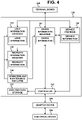
FIG. 4 is a block diagram illustrating a functional configuration of the server apparatus according toEmbodiment 1; -
FIG. 5 is a diagram illustrating device information data according toEmbodiment 1; -
FIG. 6 is a diagram illustrating service information data according toEmbodiment 1; -
FIG. 7 is a diagram illustrating user information data according toEmbodiment 1; -
FIG. 8 is a diagram illustrating property information data according toEmbodiment 1; -
FIG. 9 is a block diagram illustrating a functional configuration of the adapter device according toEmbodiment 1; -
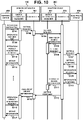
FIG. 10 is a sequence diagram illustrating a process flow of device operation (outdoor mode) executed between the server apparatus and the adapter device according toEmbodiment 1; -
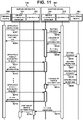
FIG. 11 is a sequence diagram illustrating a process flow of device operation (indoor mode) executed between the server apparatus and the adapter device according toEmbodiment 1; -
FIG. 12 is a sequence diagram illustrating a process flow of automatic control (server-device-route mode) executed between the server apparatus and the adapter devices according toEmbodiment 1; -
FIG. 13 is a sequence diagram illustrating a process flow of automatic control (edge-device-linking mode) executed between the server apparatus and the adapter device according toEmbodiment 1; -
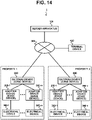
FIG. 14 is a block diagram illustrating an overall configuration of an edge device linking system according toEmbodiment 2; and -
FIG. 15 is a block diagram illustrating a functional configuration of a gateway device according toEmbodiment 2. - An edge device linking system according to Embodiment 1 is a system capable of providing services relating to electrical devices by linking of edge devices without performing communication with a server apparatus. The edge device is a device that has communication functions of transmitting information of the electrical devices to the server apparatus and receiving information from the server apparatus. In the present embodiment, the edge device is assumed to be an adapter device dedicated for an electrical device, for communicating with the server apparatus.
- As illustrated in
FIG. 1 , the edgedevice linking system 1 includes aserver apparatus 100 that provides a service, and adapter devices 200-1, ..., 200-m, 200-n connected to electrical devices 300-1, ..., 300-m, 300-n installed in a property, where m and n are natural numbers not less than 2. The property is, for example, a residence or an office building. The adapter devices 200-1, ..., 200-m and the electrical devices 300-1, ..., 300-m are installed in a property, and the adapter devices 200-1, ..., 200-n and the electrical devices 300-1, ..., 300-n are installed in aproperty 2. The adapter devices 200-1, ..., 200-m, 200-n are collectively hereinafter referred to as anadapter device 200 except where a specific adapter device is described. Similarly, the electrical devices 300-1, ..., 300-m, 300-n are collectively hereinafter referred to as anelectrical device 300 except where a specific electrical device is described. - The
server apparatus 100 is typically a cloud server and provides an IoT platform. The IoT platform collects information from theelectrical device 300 and provides services relating to theelectrical device 300. Here, the services include a service of enabling an operation of theelectrical device 300 through aterminal device 400, a service of automatic control of theelectrical device 300, and a service of automatic control of a plurality ofelectrical devices 300 by linking of a plurality of edge devices. - The
adapter device 200 is a device for connecting theelectrical device 300 installed in the property to theserver apparatus 100 where the IoT platform is built. Theadapter device 200 is externally attached to theelectrical device 300, and transmits and receives information by wired or wireless communication between theadapter device 200 and theelectrical device 300. Theadapter device 200 includes a part of functions that theserver apparatus 100 has, as described later. This can provide, without intervention of theserver apparatus 100, a service of operation of theelectrical device 300 through theterminal device 400, a service of automatic control of theelectrical device 300, and the like. - The
electrical device 300 is a device installed in a residence, such as an air conditioner, a water heater, a bathroom dehumidifier, a dressing room cooler/heater, an induction heating (IH) cooker, a bathroom cooler/heater, a lighting device, a refrigerator, a television, a floor cooling/heating system, and the like. Theelectrical device 300 includes a device installed on the premises of the residence. - The
terminal device 400 is a device used by a user who receives services provided by theserver apparatus 100. Theterminal device 400 is a personal computer, a smartphone, a tablet terminal, and the like. Theterminal device 400 has an application installed therein to use functions and services provided by theserver apparatus 100. - The
network 500 is a wireless or wired communication network, such as the Internet, an intranet, an extranet, a local area network (LAN), a virtual private network (VPN), a telephone network, and the like. - A hardware configuration of the
server apparatus 100 is described with reference toFIG. 2 . Theserver apparatus 100 includes aprocessor 11 that executes processing to realize the services provided by the IoT platform, amain storage 12 that is used as a work area for theprocessor 11, and anauxiliary storage 13 that stores various types of data to be used for processing by theprocessor 11, acommunicator 14 for communication with an external device, and a real time clock (RTC) 15 that keeps time. Themain storage 12, theauxiliary storage 13, thecommunicator 14, and theRTC 15 are all connected to theprocessor 11 via abus 16. - The
processor 11 includes a central processing unit (CPU). Theprocessor 11 achieves various functions of theserver apparatus 100 by executing a program stored in theauxiliary storage 13. - The
main storage 12 includes a random access memory (RAM). The program is loaded from theauxiliary storage 13 into themain storage 12. Themain storage 12 is then used as a work area for theprocessor 11. - The
auxiliary storage 13 includes a non-volatile memory such as an electrically erasable programmable read-only memory (EEPROM). In addition to the program, theauxiliary storage 13 stores various types of data for use in processing by theprocessor 11. Theauxiliary storage 13 supplies data to be used by theprocessor 11 to theprocessor 11 in accordance with the instructions of theprocessor 11 and stores the data supplied by theprocessor 11. - The
communicator 14 includes a network interface circuit for communicating with the external device. Thecommunicator 14 receives a signal from the external device and outputs data indicated by the signal to theprocessor 11. Thecommunicator 14 also transmits a signal indicating the data output by theprocessor 11 to the external device. - The
RTC 15 is a timekeeping device including an oscillator circuit using a quartz oscillator. For example, theRTC 15 has a built-in battery to continue the keeping of time even when theserver apparatus 100 is powered off. - Next, a hardware configuration of the
adapter device 200 is described with reference toFIG. 3 . The hardware configuration of theadapter device 200 is the same as the hardware configuration of thegateway device 600 ofEmbodiment 2, which is described later, and thusFIG. 3 also illustrates a hardware configuration of thegateway device 600. - The
adapter device 200 includes aprocessor 21 that performs processing to provide services relating to theelectrical device 300, amain storage 22 for use as a work area for theprocessor 21, anauxiliary storage 23 that stores various types of data for use in processing by theprocessor 21, a wide-area communicator 24 for communicating with an external device, alocal communicator 25 for communication with theelectrical device 300 installed in the residence, and anRTC 26 that keeps time. Themain storage 22, theauxiliary storage 23, the wide-area communicator 24, thelocal communicator 25, and theRTC 26 are all connected to theprocessor 21 via abus 27. - The
processor 21, themain storage 22, theauxiliary storage 23, and theRTC 26 have the same functions as those of theprocessor 11, themain storage 12, theauxiliary storage 13, and theRTC 15, respectively. - The wide-
area communicator 24 includes a network interface circuit for communicating with the external devices, such as theserver apparatus 100, theterminal device 400, or the like. The wide-area communicator 24 receives a signal from the external device and outputs the data indicated by the signal to theprocessor 21. The wide-area communicator 24 also transmits a signal indicating the data output by theprocessor 21 to the external device. - The
local communicator 25 includes a network interface circuit for communicating with theelectrical device 300. Thelocal communicator 25 receives a signal from theelectrical device 300 and outputs the data indicated by the signal to theprocessor 21. Thelocal communicator 25 also transmits a signal indicating the data output from theprocessor 21 to theelectrical device 300. - Next, functions of the
server apparatus 100 are described with reference toFIG. 4 . Theserver apparatus 100 functionally includes adevice information manager 101 that manages device information relating to theelectrical device 300, aservice provider 102 that manages service information, acontroller 103 that controls theelectrical device 300 via theadapter device 200, auser information manager 104 that manages user information relating to the user, aproperty information manager 105 that manages property information of the property where theelectrical device 300 is installed, an operation andmaintenance executor 106 that operates and maintains the edgedevice linking system 1 based on an instruction by an administrator, and ananalysis data storage 107 that stores data for analysis in the edgedevice linking system 1. - The
device information manager 101 manages device information with respect to theelectrical device 300. Specifically, thedevice information manager 101 receives an operation instruction for theelectrical device 300 from theterminal device 400, sends the received instruction to thecontroller 103, and registers the device information based on the information received from thecontroller 103. Thedevice information manager 101 is achieved by cooperation of theprocessor 11, themain storage 12, theauxiliary storage 13, and thecommunicator 14. - The device information is information that includes information to identify the device, setting values, such as the operation mode, set temperature, and the like of the
electrical device 300, and measurement values measured by theelectrical device 300. An example of the device information is illustrated inFIG. 5 . - The table in
FIG. 5 includes information with respect to theelectrical devices 300 installed in properties. The table inFIG. 5 includes, in association with one another, an electrical device ID to identify theelectrical device 300, a device name of theelectrical device 300, an adapter device ID to identify theadapter device 200 that is connected to theelectrical device 300, a property ID to identify a property where theelectrical device 300 is installed, a registration date and time when a measurement value and a setting value are registered, the measurement value obtained by measurement by theelectrical device 300, and the setting value set to which theelectrical device 300 is set. The measurement value, the setting value, and the registration date and time are updated each time the information with respect to the measurement value and the setting value are received from thecontroller 103. - The record in the first row of the table in
FIG. 5 indicates that the electrical device with the electrical device ID "1-1" has the device name "water heater " and is connected to the adapter device with the adapter device ID "1-1", and is installed in a property indicated by the property ID "1"; and the measurement value and the setting value are registered at "19:00:00 on December 1, 2019", the measurement value, that is, the current hot water supply temperature, is "30°C", and the setting value, that is, the set hot water supply temperature, is "40°C". - The
service provider 102 ofFIG. 4 manages execution of the services provided by theserver apparatus 100. Specifically, theservice provider 102 receives a request for registration of a service from theterminal device 400 and registers content of the service as service information. Theservice provider 102 determines, based on the service information, whether or not to operate theelectrical device 300. Theservice provider 102 is achieved by cooperation of theprocessor 11, themain storage 12, theauxiliary storage 13, and thecommunicator 14. Theservice provider 102 is an example of second service provision means. - The service information is information including information with respect to the property for which the service is to be performed and the content of the service. The content of the service includes action information indicating the operation of the
electrical device 300 and event information indicating a condition under which the operation is to be performed. Theservice provider 102 determines whether the value indicated by the device information satisfies the condition indicated by the event information, and when determination is made that the value indicated by the device information satisfies the condition, provides an instruction to make theelectrical device 300 perform the operation indicated by the action information. An example of the service information is illustrated inFIG. 6 . - In the table in
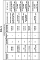
FIG. 6 , a service ID to identify the service, a service name, a property ID to identify the property for which the service is provided, event information, and action information are registered in association with one another. The event information includes the electrical device ID and condition information, and the action information includes the electrical device ID and operation information. When a state of the electrical device indicated by the electrical device ID in the event information satisfies the content of the condition information, theservice provider 102 sends to thecontroller 103 an instruction to cause the electrical device indicated by the electrical device ID in the action information to perform the operation indicated by the operation information. - The record in the first row of the table in
FIG. 6 shows that the service ID "1-1" indicates a service to "link a water heater and a bathroom dehumidifier", and this service is a service performed in the property with the property ID "1", and when the operation mode of the electrical device indicated by the electrical device ID " 1-1", that is, the water heater, turns into "hot water supply", the electrical device indicated by ID "1-2", that is, the bathroom humidifier, is caused to operate in the operation mode "heating", and the setting temperature is set to "20°C". - The service that is "link between water heater and bathroom dryer" with the service ID "1-1" in
FIG. 6 is a service that causes the bathroom dehumidifier to operate in a heating operation when water heating of the water heater starts, which helps prevent thermal shock. The service that is "link between air conditioner and bathroom cooler/heater" with the service ID "2-1" is a service that causes the bathroom cooler/heater to operate in a heating operation when a difference between the living room temperature measured by the air conditioner and the bathroom temperature measured by the bathroom heater/cooler exceeds a threshold, which also helps prevent thermal shock. The service that is "link between air conditioner and IH cooker" with the service ID "1-2" is a service of turning off the power of the IH cooker upon the air conditioner detecting the onset of sleep of the user using information obtained from an infrared sensor, which helps prevent the user from forgetting to turn off the IH cooker. - The
service provider 102 also determines whether the service indicated in the service information can be provided by the edge device such as theadapter device 200. Whether or not the service can be provided by the edge device is determined based on the relationship between the edge devices. For example, as for a service that links multiple electrical devices, determination is made that provision of the service by theadapter device 200 is achievable in a case where the adapter device of one electrical device can control the adapter device of another electrical device, multiple electrical devices are connected to the same adapter device, multiple electrical devices are connected to the same gateway device, or the like. Upon determining that the service can be provided by theadapter device 200, theservice provider 102 causes a later-describedservice provider 202 of theadapter device 200 to register the service information. - The
controller 103 ofFIG. 4 controls the operation of theelectrical device 300 via theadapter device 200. Specifically, thecontroller 103 receives the instruction to operate theelectrical device 300 from various components of theserver apparatus 100 and transmits the instruction to theadapter device 200. Thecontroller 103 periodically collects data, such as measurement values and setting values, from theelectrical device 300 via theadapter device 200. Thecontroller 103 is achieved by cooperation of theprocessor 11 and thecommunicator 14. - The term "periodically collects" refers to the fact that the
controller 103 repeatedly collects data from theelectrical device 300, and the intervals at which the data is collected are not limited to fixed intervals. The interval can be arbitrarily set by an administrator of the edgedevice linking system 1. The interval may be set in accordance with a predetermined rule or may be set to an irregular value. - The
user information manager 104 ofFIG. 4 manages user information about a user who uses theelectrical device 300. Specifically, theuser information manager 104 receives registration of the user information from theterminal device 400 and registers the received information. Theuser information manager 104 is achieved by cooperation of theprocessor 11, themain storage 12, theauxiliary storage 13, and thecommunicator 14. An example of the user information is illustrated inFIG. 7 . - In the table in
FIG. 7 , a user ID to identify a user, a user name, an e-mail address, gender, and an address are registered in association with one another. - The record in the first row of the table in
FIG. 7 indicates that the name of the user with the user ID "1" is "Jane Smith", the email address is "aaa@aaa.com", the gender is "female", and the address is "1-1-1, xx, A, Tokyo". - The
property information manager 105 ofFIG. 4 manages property information about the property where theelectrical device 300 is installed. Specifically, theproperty information manager 105 receives registration of the property information from theterminal device 400 and registers the received information. Theproperty information manager 105 is achieved by cooperation of theprocessor 11, themain storage 12, theauxiliary storage 13, and thecommunicator 14. An example of the property information is illustrated inFIG. 8 . - In the table of
FIG. 8 , a property ID to identify a property, a property name, an address, and a user ID to identify a user who is a user of theelectrical device 300 installed in the property are registered in association with one another. - The record in the first row of the table in
FIG. 8 indicates that the property name of the property ID "1" is "home," the address is "1-1-1, xx, A, Tokyo", and the user of theelectrical device 300 installed in the property is the user with the user ID "1". - The operation and
maintenance executor 106 ofFIG. 4 operates and maintains the edgedevice linking system 1 based on an instruction of the administrator of the edgedevice linking system 1. The operation andmaintenance executor 106 accesses thedevice information manager 101, theuser information manager 104, and theproperty information manager 105, and acquires and rewrites information. The operation andmaintenance executor 106 is achieved by cooperation of theprocessor 11 and thecommunicator 14. - The
analysis data storage 107 ofFIG. 4 collects and stores data about theelectrical device 300 via thecontroller 103. Theanalysis data storage 107 provides the stored data based on the instructions of the administrator of the edgedevice linking system 1, a person who has received a license to use the data, or the like. Theanalysis data storage 107 is achieved by cooperation of theprocessor 11, themain storage 12, theauxiliary storage 13, and thecommunicator 14. - Next, functions of the
adapter device 200 are described with reference toFIG. 9 . Theadapter device 200 includes some of the functions of theserver apparatus 100. Specifically, theadapter device 200 includes adevice information manager 201, aservice provider 202, and acontroller 203. - The
device information manager 201 manages device information with respect to theelectrical devices 300 connected to theadapter device 200. Specifically, thedevice information manager 201 receives an instruction for operation of theelectrical device 300 from theterminal device 400, sends the received instruction to thecontroller 203, and registers the device information based on the information received from thecontroller 203. Thedevice information manager 201 is achieved by cooperation of theprocessor 21, themain storage 22, theauxiliary storage 23, and the wide-area communicator 24. Thedevice information manager 201 is an example of device information management means. - The device information managed by the
device information manager 201 has the same items as the items included in the table inFIG. 5 , but only includes information with respect to theelectrical device 300 connected to theadapter device 200. Here, the connectedelectrical device 300 includes both a physically connected electrical device and a logically connected electrical device. For example, in a case where theadapter device 200 is an adapter device externally attached to the water heater with the electrical device ID "1-1," the device information managed by thedevice information manager 201 of theadapter device 200 includes only the device information associated with the electrical device ID "1-1" in the table inFIG. 5 . - The
service provider 202 ofFIG. 9 manages execution of services. Specifically, theservice provider 202 receives from theserver apparatus 100 an instruction to register a service, and registers content of the service as service information. Theservice provider 202 determines, based on the service information, whether or not to allow operation of theelectrical device 300. Theservice provider 202 is achieved by cooperation of theprocessor 21, themain storage 22, theauxiliary storage 23, and the wide-area communicator 24. Theservice provider 202 is an example of first service provision means and service provision means. - The service information managed by the
service provider 202 has the same items as the items included in the table inFIG. 6 , but only includes information with respect to the service directed to theelectrical device 300 connected to theadapter device 200. For example, in a case where theadapter device 200 is an adapter device externally attached to the water heater with the electrical device ID "1-1," the service information managed by theservice provider 202 includes only the service information associated with the electrical device ID "1-1" included in the event information in the table inFIG. 6 . - The
controller 203 ofFIG. 9 controls operation of theelectrical device 300 connected to theadapter device 200. Specifically, thecontroller 203 receives an instruction for operation of theelectrical device 300 from thedevice information manager 201 and theservice provider 202, and transmits the instruction to theelectrical device 300. Thecontroller 203 receives an instruction for operation of theelectrical device 300 from thecontroller 103 of theserver apparatus 100 and transmits the instruction to theelectrical device 300. Thecontroller 203 periodically collects data, such as measurement values and setting values, from theelectrical device 300. Thecontroller 203 is achieved by cooperation of theprocessor 21, the wide-area communicator 24, and thelocal communicator 25. Thecontroller 203 is an example of control means. - An application programming interface (API) for transmitting and receiving information between the
server apparatus 100 ofFIG. 5 and an external device such as theterminal device 400 is the same as that of the API for transmitting and receiving information between theadapter device 200 ofFIG. 9 and the external device. - Next, operation of the edge
device linking system 1 of the present embodiment is described.FIGS. 10 to 13 are sequence diagrams illustrating flows of processing performed among theserver apparatus 100, theadapter device 200, theelectrical device 300, and theterminal device 400 when services are provided in the edgedevice linking system 1. -
FIGS. 10 and11 are sequence diagrams illustrating flows of processing relating to a service that enables device operation relative to anelectrical device 300 by aterminal device 400.FIGS. 12 and13 are sequence diagrams illustrating flows of processing relating to a service for automatically controlling a plurality ofelectrical devices 300. - First,
FIGS. 10 and11 are described. The sequence diagram inFIG. 10 illustrates a case where the user is located outside the property and operates theelectrical device 300 installed inside the property from outside. The sequence diagram inFIG. 11 illustrates a case where the user is located inside the property and operates theelectrical device 300 from inside the property. Here, the property is referred to as a house, and a mode of operation in which theelectrical device 300 inside the property is operated from outside is referred to as an "outdoor mode", and a mode of operation in which theelectrical device 300 is operated from inside the property is referred to as an "indoor mode". The user of theterminal device 400 sets in advance in which mode, the outdoor mode or the indoor mode, theelectrical device 300 is to be operated. - The process flow of device operation in the outdoor mode of
FIG. 10 is described. - When a user issues an instruction for the operation of the
electrical device 300 using an application of theterminal device 400, theterminal device 400 transmits an operation instruction to thedevice information manager 101 of the server apparatus 100 (step S101). The operation instruction includes, for example, the electrical device ID and the setting value of theelectrical device 300. Upon receiving the operation instruction, thedevice information manager 101 of theserver apparatus 100 sends to the controller 103 a setting request to set the setting value of the electrical device 300 (step S102). Thedevice information manager 101 also transmits to theterminal device 400 information indicating the operation date and time when the operation instruction is received (step S103). Thecontroller 103 sends the setting request to thecontroller 203 of theadapter device 200 connected to theelectrical device 300 relating to the setting request (step S104). - The
controller 203 of theadapter device 200 sends an instruction to thedevice information manager 201 to change the setting value in the device information to the setting value included in the setting request (step S105). Thedevice information manager 201 updates the information of the setting value in the device information and sends a setting request to the controller 203 (step S106). Thecontroller 203 sends the setting request to theelectrical device 300 connected to the adapter device 200 (step S107). Upon receiving from the electrical device 300 a setting response indicating that the setting to the setting value relating to the setting request has been completed (step S108), thecontroller 203 transmits to theelectrical device 300 an information request for requesting information with respect to the measurement value measured by the electrical device 300 (step S109). Upon receiving from theelectrical device 300 an information response that includes information with respect to the measurement values (step S110), thecontroller 203 sends to thedevice information manager 201 an instruction to change the measurement value in the device information to the measurement value included in the information response (step Sill), and thedevice information manager 201 updates the device information. Thecontroller 203 also sends to thecontroller 103 of the server apparatus 100 a setting response indicating that the setting is completed (step S112). This setting response includes the measurement value received in step S110. - Upon receiving the setting response, the
controller 103 of theserver apparatus 100 sends to thedevice information manager 101 an instruction to change the measurement value in the device information to the measurement value included in the setting response (step S113), and thedevice information manager 101 updates the device information. - The
terminal device 400 periodically transmits to thedevice information manager 101 of theserver apparatus 100 an acquisition request to acquire the operation result (step S114), and thedevice information manager 101 transmits, as a response to the acquisition request, the device information obtained at the time of receiving the acquisition request (step S115). When theterminal device 400 transmits an acquisition request after the device information is updated (step S116), thedevice information manager 101 transmits the updated device information to the terminal device 400 (step S117). Theterminal device 400 notifies the user of the received device information by displaying the device information on the screen. - Next, the process flow of device operation in the indoor mode of
FIG. 11 is described. - When the user issues an instruction for the operation of the
electrical device 300 using an application of theterminal device 400, theterminal device 400 transmits an operation instruction to thedevice information manager 201 of the adapter device 200 (step S201). Upon receiving the operation instruction, thedevice information manager 201 of theadapter device 200 sends to the controller 203 a setting request to set the setting value of the electrical device 300 (step S202). Thedevice information manager 201 of theadapter device 200 transmits to theterminal device 400 information indicating the operation date and time when the operation instruction is received (step S203). - The
controller 203 of theadapter device 200 sends to thedevice information manager 201 an instruction to change the setting value of the device information to the setting value included in the setting request (step S204). Thedevice information manager 201 updates the information on the setting value of the device information and sends a setting request to the controller 203 (step S205). Thecontroller 203 transmits the setting request to theelectrical device 300 connected to the adapter device 200 (step S206). Upon receiving from the electrical device 300 a setting response indicating that the setting to the setting value relating to the setting request has been completed (step S207), thecontroller 203 sends to theelectrical device 300 an information request for requesting information with respect to the measurement value measured by the electrical device 300 (step S208). Upon receiving from theelectrical device 300 an information response that includes information with respect to the measurement value (step S209), thecontroller 203 sends to thedevice information manager 201 an instruction to change the measurement value in the device information to the measurement value included in the information response (step S210), and thedevice information manager 201 updates the device information. - The
terminal device 400 periodically transmits to thedevice information manager 201 of theadapter device 200 an acquisition request to acquire the operation results (step S211), and thedevice information manager 201 transmits, as a response to the acquisition request, the device information obtained at the time of receiving the acquisition request (step S212). When theterminal device 400 transmits an acquisition request after the device information is updated (step S213), thedevice information manager 201 transmits the updated device information to the terminal device 400 (step S214). Theterminal device 400 notifies the user of the received device information by displaying the device information on the screen. - The
controller 203 of theadapter device 200 transmits to thecontroller 103 of the server apparatus 100 a setting response indicating that the setting is completed (step S215). This setting response includes the setting value included in the operation instructions in step S201 and the measurement value received in step S209. Upon receiving the setting response, thecontroller 103 of theserver apparatus 100 sends to thedevice information manager 101 an instruction to change the setting value and the measurement value of the device information to the setting value and measurement value included in the setting response (step S216), and thedevice information manager 101 updates the device information. - Next,
FIGS. 12 and13 are described. The sequence diagrams ofFIGS. 12 and13 illustrate cases where a user uses a service to automatically control a plurality ofelectrical devices 300.FIG. 12 illustrates a case where the operation of theelectrical devices 300 is controlled via theserver apparatus 100 in this automatic control service, and this control mode is hereinafter referred to as "server-device-route mode". The sequence diagram inFIG. 13 illustrates a case where the operation of theelectrical devices 300 is controlled by linking of theadapter devices 200 in the above automatic control service, and this control mode is hereinafter referred to as "edge-device-linking mode". The user of theterminal device 400 sets in advance in which mode, the server-device-route mode or the edge-device-linking mode, the service is to be used. - The flow of the automatic control process in the server-device-route mode of
FIG. 12 is described. - When a user issues an instruction for the registration of a service using an application of the
terminal device 400, theterminal device 400 transmits a request for registration of the service to theservice provider 102 of the server apparatus 100 (step S301). Theservice provider 102 updates the service information based on the content of the service relating to the registration request and transmits notification of completion of the registration to the terminal device 400 (step S302). - On the other hand, the
controller 203 of the adapter device 200-1 periodically transmits an information request for requesting information with respect to the measurement value measured by the electrical device 300-1 (step S303) and receives an information response including information with respect to the measurement value from the electrical device 300-1 (step S304). The periodic transmission of information request and reception of information responses are also performed between the adapter device 200-2 and the electrical device 300-2, but these processes are omitted inFIG. 12 . Thecontroller 203 of the adapter device 200-1 sends to thedevice information manager 201 an instruction to change the measurement value in the device information to the measurement value included in the information response (step S305), and thedevice information manager 201 updates the device information and notifies thecontroller 203 of the updated device information (step S306). Thecontroller 203 transmits to thecontroller 103 of theserver apparatus 100 the updated device information to notify thecontroller 103 of the updated device information (step S307). - The
controller 103 of theserver apparatus 100 sends to thedevice information manager 101 an instruction for updating to the received device information (step S308), and thedevice information manager 101 updates the device information. Thedevice information manager 101 then sends to the service provider 102 a change notification indicating that the device information is changed (step S309). Upon receiving the notification of the change in the device information, theservice provider 102 determines, with reference to the event information included in the service information, whether or not the state of the electrical device 300-1 satisfies the condition indicated by the event information (step S310). This determination is hereinafter referred to as "event determination". Upon determining that the state of the electrical device 300-1 satisfies the condition indicated by the event information, theservice provider 102 sends to thecontroller 103 an action execution instruction to cause theelectrical device 300 indicated by the action information to perform the operation indicated by the action information (step S311). - Here, the
electrical device 300 indicated by the action information is assumed to be the electrical device 300-2. When thecontroller 103 receives the action execution instruction, the process from step S 104 to step S 117 of the device operation in the outdoor mode illustrated inFIG. 10 is performed among theserver apparatus 100, the adapter device 200-2, the electrical device 300-2, and the terminal device 400 (step S312). Specifically, thecontroller 103 transmits a setting request to the adapter device 200-2 connected to the electrical device 300-2 (step S104), and the processing of step S105 and the subsequent steps is performed. - When the
service provider 102 sends an action execution notification to thecontroller 103, theservice provider 102 transmits to theterminal device 400 an execution notification that the action indicated in the action information has been executed (step S313). - For example, in an example case of a process to perform a service that is to "link between water heater and bathroom dehumidifier" indicated by the service ID "1-1" of the service information in
FIG. 6 ", the electrical device 300-1 is considered to be a water heater and the electrical device 300-2 is considered to be a bathroom dehumidifier in the sequence diagram ofFIG. 12 . In step S304, when a response indicating start of water heating is transmitted from the water heater, processing of steps S305 and S306 is performed in the adapter device of the water heater, and the adapter device transmits to the server apparatus 100 a notification indicating start of the water supply (step S307). After theserver apparatus 100 performs the processing of steps S308 and S309, theservice provider 102 makes an event determination (step S310) and sends to thecontroller 103 an action execution instruction to cause the bathroom dehumidifier to perform heating operation at the set temperature of 20°C. Thecontroller 103 transmits a setting request to the adapter device of the bathroom dehumidifier, and the process of device operation in the outdoor mode is started (step S312). - Next, the process flow of automatic control in the edge-device-linking mode of
FIG. 13 is described. InFIG. 13 , the adapter device 200-1 is an example of a first edge device, the adapter device 200-2 is an example of a second edge device, the electrical device 300-1 is an example of a first electrical device, and the electrical device 300-2 is an example of a second electrical device. - The processing of steps S401 and S402 in
FIG. 13 is the same as the processing of steps S301 and S302 inFIG. 12 . Theservice provider 102 determines whether or not theadapter device 200 can provide a registered service (step S403). For example, the content of the service is assumed to be the link between the electrical devices 300-1 and 300-2, and that theservice provider 102 is assumed to determine that the adapter device 200-1 of electrical device 300-1 can provide the service. In this case, theservice provider 102 sends to the controller 103 a registration instruction to instruct the adapter device 200-1 to register the service (step S404), and thecontroller 103 transmits the registration instruction of the service to thecontroller 203 of the adapter device 200-1 (step S405). The registration instruction includes information with respect to the items indicated in the service information inFIG. 6 . - The
controller 203 of the adapter device 200-1 sends the service registration instruction to the service provider 202 (step S406), and theservice provider 202 registers the service in the service information managed by the adapter device 200-1 based on the information included in the registration instruction. - On the other hand, the
controller 203 of the adapter device 200-1 periodically transmits an information request for requesting information with respect to the measurement value measured by the electrical device 300-1 (step S407) and receives an information response including information with respect to the measurement value from the electrical device 300-1 (step S408). The periodic transmission of information requests and reception of information responses are also performed between the adapter device 200-2 and the electrical device 300-2, but these processes are omitted inFIG. 13 . Thecontroller 203 of the adapter device 200-1 sends to thedevice information manager 201 an instruction to change the measurement value in the device information to the measurement value included in the information response (step S409), and thedevice information manager 201 updates the device information and sends to the service provider 102 a change notification indicating that the device information is changed (step S410). - Upon receiving the notification of the change in the device information, the
service provider 202 performs, with reference to the event information included in the service information, an event determination for the state of the electrical device 300-1 (step S411). Upon determining that the state of the electrical device 300-1 satisfies the condition indicated in the event information, theservice provider 202 sends to thecontroller 203 an action execution instruction to cause the electrical device 300-2 to perform the operation indicated in the action information (step S412). Theservice provider 202 transmits to theterminal device 400 an execution notification that the action indicated in the action information is executed (step S413). - Upon receiving the action execution instruction, the
controller 203 of the adapter device 200-1 sends the action execution instruction to thecontroller 203 of the adapter device 200-2 to which the electrical device 300-2 is connected (step S414), and the processing of steps S204 to S216 of the device operation in the indoor mode illustrated inFIG. 11 is performed among theserver apparatus 100, adapter device 200-2, electrical device 300-2, and terminal device 400 (step S415). - For example, in an example case of a process to perform a service that is to "link between air conditioner and IH cooker" indicated by the service ID "1-2" of the service information in
FIG. 6 , the electrical device 300-1 is considered to be an air conditioner and the electrical device 300-2 is considered to be an IH cooking device in the sequence diagram ofFIG. 13 . In step S408, when a response indicating detection of user's sleep onset is transmitted from the air conditioner, processing of steps S409 to S413 is performed in the adapter device of the air conditioner. Then, thecontroller 203 of the adapter device of the air conditioner transmits, to thecontroller 203 of the adapter device of the IH cooker, an action execution instruction to turn off the power of the IH cooker (step S414), and the process of the device operation in the indoor mode to turn off the power is started (step S415). - Use of services provided by the IoT platform with respect to electrical devices heretofore requires communication with a server apparatus. However, the device operation in the indoor mode and the automatic control in the edge-device-linking mode of the present embodiment enables control of the electrical devices without the intervention of the server apparatus. This enables control of the electrical devices even when communication with the server apparatus is interrupted due to a network failure. Also, increasing the amount of processing that can be performed by the edge device can reduce the amount of communication with the server apparatus.
- Also, having the edge device have a service providing function of the server apparatus of the present embodiment can achieve such autonomous linking processing by the edge device as the automatic control in the edge-device-linking mode.
- Also, having the edge device have a device information management function and a service providing function of the server device in the present embodiment can achieve control of the electrical devices without intervention via the server apparatus, and thus processing that requires high real-time performance can be performed. For example, for electrical devices such as the IH cooker, the bathroom dehumidifier, and the bathroom air conditioner, which might pose a danger to the user if the electrical devices are not controlled immediately, danger can be avoided by controlling the electrical devices in the indoor mode and the edge-device-linking mode.
- Also, since the edge device and server apparatus of the present embodiment use a common API, the burden of development can be reduced.
- The edge
device linking system 1 according toEmbodiment 2 is a system in which a gateway device is added to the edgedevice linking system 1 according toembodiment 1. - As illustrated in
FIG. 14 , the edgedevice linking system 1 includes aserver apparatus 100 that provides a service, anadapter device 200 that is connected to anelectrical device 300 installed in a property, and agateway device 600 installed in each property. The gateway device connects to theadapter device 200 in the same property where the gateway device is installed. In the present embodiment, the edge device includes thegateway device 600 that relays the communication between theserver apparatus 100 and theadapter device 200. - Functions of the
server apparatus 100 and theadapter device 200 are similar to those ofEmbodiment 1. - Functions of the
gateway device 600 are described with reference toFIG. 15 . Thegateway device 600 includes some of functions of theserver apparatus 100. Specifically, thegateway device 600 includes adevice information manager 601 that manages device information relating to theelectrical device 300, aservice provider 602 that manages service information, acontroller 603 that controls theelectrical device 300 via theadapter device 200, auser information manager 604 that manages user information relating to the user, and aproperty information manager 605 that manages property information about the property where theelectrical device 300 is installed. - The
device information manager 601 manages the device information of theelectrical device 300 connected to theadapter device 200 to which thegateway device 600 is connected. Specifically, thedevice information manager 601 receives from theterminal device 400 an instruction for operation of theelectrical device 300, sends the received instruction to thecontroller 603, and registers the device information based on the information received from thecontroller 603. Thedevice information manager 601 is achieved by cooperation of theprocessor 21, themain storage 22, theauxiliary storage 23, and the wide-area communicator 24. Thedevice information manager 601 is an example of device information management means. - The device information managed by the
device information manager 601 has the same items as the items included in the table inFIG. 5 , but only includes information with respect to theelectrical device 300 connected to thegateway device 600 via theadapter device 200. Here, the connected electrical device includes both a physically connected electrical device and a logically connected electrical device. For example, in the case of thegateway device 600 installed in theproperty 1, the device information managed by thedevice information manager 601 includes only the device information associated with the property ID "1" in the table inFIG. 5 . - The
service provider 602 ofFIG. 15 manages execution of services. Specifically, theservice provider 602 receives from theserver apparatus 100 an instruction to register a service and registers the contents of the service as service information. Theservice provider 602 determines, based on the service information, whether or not to operate theelectrical device 300. Theservice provider 602 is achieved by cooperation of theprocessor 21, themain storage 22, theauxiliary storage 23, and the wide-area communicator 24. Theservice provider 602 is an example of the first service provision means and the service provision means. - The service information managed by the
service provider 602 has the same items as the items included in the table inFIG. 6 , but only includes information relating to the service directed to theelectrical device 300 connected to thegateway device 600 via theadapter device 200. For example, in the case of thegateway device 600 installed inproperty 1, the service information managed by theservice provider 602 only includes the service information associated with property ID "1" in the table inFIG. 6 . - The
controller 603 ofFIG. 15 controls operation of theelectrical device 300 connected to thegateway device 600 via theadapter device 200. Specifically, thecontroller 603 receives an instruction for operation of theelectrical device 300 from thedevice information manager 601 and theservice provider 602, and transmits the instruction to theelectrical device 300 via thecontroller 203 of theadapter device 200. Thecontroller 603 also receives an instruction for operation of theelectrical device 300 from thecontroller 103 of theserver apparatus 100 and transmits the instruction to theelectrical device 300 via thecontroller 203 of theadapter device 200. Thecontroller 603 periodically collects data, such as measurement values and setting values, from theelectrical device 300 via thecontroller 203 of theadapter device 200. Thecontroller 603 is achieved by cooperation of theprocessor 21, the wide-area communicator 24, and thelocal communicator 25. - The
user information manager 604 ofFIG. 15 manages user information about a user who uses theelectrical device 300. Specifically, theuser information manager 604 receives registration of user information from theterminal device 400 and registers the received information. Theuser information manager 604 is achieved by cooperation of theprocessor 21, themain storage 22, theauxiliary storage 23, and the wide-area communicator 24. - The user information managed by the
user information manager 604 is the same as the items included in the table inFIG. 7 , but only includes information relating to the user who is the user of theelectrical device 300 connected to thegateway device 600 via theadapter device 200. For example, in the case of thegateway device 600 installed inproperty 1, the user information managed by theuser information manager 604 only includes the information of the user of theelectrical device 300 included inproperty 1. Assuming that the user of theelectrical device 300 included inproperty 1 is the user with user ID "1," the user information managed by theuser information manager 604 only includes the information of the user associated with the user ID "1" in the table inFIG. 7 . - The
property information manager 605 ofFIG. 15 manages the property information with respect to the property where thegateway device 600 is installed. Specifically, theproperty information manager 605 receives the registration of property information from theterminal device 400 and registers the received information. Theproperty information manager 605 is achieved by cooperation of theprocessor 21, themain storage 22, theauxiliary storage 23, and the wide-area communicator 24. - The property information managed by the
property information manager 605 is the same as the items included in the table inFIG. 8 , but only includes information about the property where thegateway device 600 is installed. For example, in the case of thegateway device 600 installed in theproperty 1, the property information managed by theproperty information manager 605 only includes the property information associated with the property ID "1" in the table inFIG. 8 . - For example, upon a user instructing the
gateway device 600 installed in the property with the property ID "1" to register the property information by specifying the property name using the application of theterminal device 400, theterminal device 400 transmits a registration request to thegateway device 600, and theproperty information manager 605 of thegateway device 600 updates the property information based on the contents of the registration request. Theproperty information manager 605 then notifies theterminal device 400 of completion of the registration. Theproperty information manager 605 transmits the registered property information to thecontroller 103 of theserver apparatus 100, and theproperty information manager 105 of theserver apparatus 100 updates the property information with the content of the transmitted property information. - The API for transmitting and receiving information between the
gateway device 600 and the external device inFIG. 15 is the same as the APIs used in theserver apparatus 100 and theadapter device 200. - Next, operation of the edge
device linking system 1 of the present embodiment is described. The following describes parts different from the process flow of the operation of the edgedevice linking system 1 ofEmbodiment 1. - In the process of the device operation in the outdoor mode in the edge
device linking system 1 ofEmbodiment 2, thegateway device 600 relays the transmission and reception of information between theserver apparatus 100 and theadapter device 200 in the sequence diagram ofFIG. 10 . Furthermore, the device information is also updated in thedevice information manager 601 of thegateway device 600. - In the process of device operation in the indoor mode in the edge
device linking system 1 ofEmbodiment 2, thegateway device 600 relays the transmission and reception of information between theterminal device 400 and theadapter device 200 in the sequence diagram ofFIG. 11 and between theserver apparatus 100 and theadapter device 200 in the sequence diagram ofFIG. 11 . In addition, the device information is updated also in thedevice information manager 601 of thegateway device 600. - In the process of automatic control in the server-device-route mode in the edge
device linking system 1 ofEmbodiment 2, thegateway device 600 relays the transmission and reception of information between theserver apparatus 100 and the adapter devices 200-1, 200-2 in the sequence diagram ofFIG. 12 . Furthermore, the device information is updated also in thedevice information manager 601 of thegateway device 600. - In the process of automatic control in the edge-device-linking mode in the edge
device linking system 1 ofEmbodiment 2, thegateway device 600 relays the transmission and reception of information between theserver apparatus 100 and the adapter devices 200-1, 200-2 in the sequence diagram ofFIG. 13 . The device information is updated in thedevice information manager 601 of thegateway device 600. Theservice provider 602 of thegateway device 600 performs service registration, event determination, action execution instruction, and action execution notification; and the adapter device 200-1 does not perform these processes. Thegateway device 600 is an example of the first edge device. - According to the present embodiment, effects similar to those produced by the edge
device linking system 1 ofembodiment 1 can be achieved. - Since the server apparatus where the IoT platform is built manages information with respect to a large number of users and properties, processing such as registration, modification, and the like may be requested at the same time. In such cases, processing of the request would take much time and the amount of data communication would be high. However, according to the present embodiment, since the gateway device has a user management function and a property management function, a user can perform processing such as registration, modification, and the like in the gateway device with no need to access the server apparatus every time the processing is performed. Then, the gateway device transmits, to the server apparatus, information relating to the registration and the modification at a freely selected timing, thereby achieving reduction of the amount of data communication.
- Although some embodiments of the present disclosure are described above, various modifications and applications are possible in implementing the present disclosure.
- In
Embodiment 1 andEmbodiment 2, eachadapter device 200 includes thedevice information manager 201 and theservice provider 202, but configuration of the present disclosure is not limited thereto. Thedevice information manager 201 and theservice provider 202 may optionally be included only in aspecific adapter device 200, and theother adapter devices 200 may optionally include only thecontroller 203. - Also, in
Embodiment 2, thedevice information manager 601 and theservice provider 602 may optionally be included only in thegateway device 600, and theadapter device 200 connected to thegateway device 600 may optionally include only thecontroller 203. - In
Embodiment 2, onegateway device 600 is installed for one property, but onegateway device 600 may be installed for multiple properties. In this case, theuser information manager 604 of thegateway device 600 manages the plurality of user information for using theelectrical device 300 of each property, and theproperty information manager 605 manages the property information of the plurality of properties. - In
Embodiment 1 andEmbodiment 2, theadapter device 200 and thegateway device 600, which are the edge devices, have some functions of theserver apparatus 100, but the functions provided by the edge devices are not limited to the functions shown inEmbodiment 1 andEmbodiment 2. For example, the functions provided by the edge devices may be determined based on memory capacities available in the edge devices. Alternatively, the edge device may be determined to have the functions of collecting and updating information offline. - The foregoing describes some example embodiments for explanatory purposes. Although the foregoing discussion has presented specific embodiments, persons skilled in the art will recognize that changes may be made in form and detail without departing from the broader spirit and scope of the invention. Accordingly, the specification and drawings are to be regarded in an illustrative rather than a restrictive sense. This detailed description, therefore, is not to be taken in a limiting sense, and the scope of the invention is defined only by the included claims, along with the full range of equivalents to which such claims are entitled.
- The present disclosure can provide an edge device linking system, a method for coordinating edge devices, and a program that can provide a service relating to electrical devices by linking between edge devices without performing communication with a server apparatus.
-
- 1 Edge linking system
- 11, 21 Processor
- 12, 22 Main storage
- 13, 23 Auxiliary storage
- 14 Communicator
- 15, 26RTC
- 16, 27Bus
- 24 Wide-area communicator
- 25 Local communicator
- 100 Server apparatus
- 101, 201, 601 Device information manager
- 102, 202, 602 Service provider
- 103, 203, 603 Controller
- 104, 604 User information manager
- 105, 605 Property information manager
- 106 Operation and maintenance executor
- 107 Analysis data storage
- 200, 200-1, ..., 200-m, 200-n Adapter device
- 300, 300-1, ..., 300-m, 300-n Electrical device
- 400 Terminal device
- 500 Network
- 600 Gateway device
Claims (7)
- An edge device linking system, comprising:a first edge device to be connected to a first electrical device;a second edge device to be connected to a second electrical device; anda server apparatus to provide a service relating to the first electrical device and the second electrical device, whereinthe first edge device, the second edge device, and the server apparatus are communicatively connected to one another,the first edge device includesdevice information management means for managing device information with respect to the first electrical device, andfirst service provision means for managing service information and providing the service based on the service information, the service information indicating content of the service and including action information indicating an operation of the second electrical device and event information indicating a condition for executing the operation indicated by the action information,the second edge device includes control means for controlling the operation of the second electrical device, andwhen the first service provision means of the first edge device determines that the device information with respect to the first electrical device satisfies the condition indicated by the event information, the first service provision means of the first edge device causes the control means of the second edge device to control the second electrical device to perform the operation indicated by the action information.
- The edge device linking system according to claim 1, whereinthe server apparatus comprises second service provision means for receiving a registration request of the service information, andthe second service provision means determines, based on a relationship between the first edge device and the second edge device, whether provision of the service indicated by the service information relating to the registration request is achievable by the first edge device, and when determination is made that the provision is achievable, the second service provision means causes the first service provision means of the first edge device to manage the received service information.
- The edge device linking system according to claim 1 or 2, wherein application programming interfaces (APIs) for performing transmission and reception of information between the first edge device and an external device and between the second edge device and the external device are a same as an API for performing transmission and reception of information between the server apparatus and the external device.
- The edge device linking system according to any one of claims 1 to 3, whereinthe first edge device is an adapter device that enables communication of the first electrical device with the server apparatus, andthe second edge device is an adapter device that enables communication of the second electrical device with the server apparatus.
- The edge device linking system according to any one of claims 1 to 3, whereinthe first edge device is a gateway device that relays communication of the server apparatus with an adapter device connected to the first electrical device and with an adapter device connected to the second electrical device,the gateway device communicates with the first electrical device via the adapter device connected to the first electrical device, andthe second edge device is an adapter device connected to the second electrical device and communicates with the server apparatus via the gateway device.
- An edge device linking method executable in an edge device linking system in which a first edge device connected to a first electrical device, a second edge device connected to a second electrical device, and a server apparatus to provide a service relating to the first electrical device and the second electrical device are communicatively connected to one another, the method comprising:managing, by device information management means of the first edge device, device information with respect to the first electrical device, andcausing, by service provision means of the first edge device, control means of the second edge device to control the second electrical device to perform an operation indicated by action information indicating the operation of the second electrical device, when the service provision means of the first edge device determines, with reference to service information indicating content of the service and including the action information and event information indicating a condition for executing the operation indicated by the action information, that the device information with respect to the first electrical device satisfies the condition indicated by the event information.
- A program causing a computer connected to a first electrical device to function as:device information management means for managing device information with respect to the first electrical device, andservice provision means for causing a computer connected to a second electrical device to control the second electrical device to perform an operation indicated by action information indicating the operation of the second electrical device, when the service provision means determines, with reference to service information indicating content of a service relating to the first electrical device and the second electrical device and including the action information and event information indicating a condition for executing operation indicated by the action information, that device information with respect to the first electrical device satisfies the condition indicated by the event information.
Applications Claiming Priority (1)
| Application Number | Priority Date | Filing Date | Title |
|---|---|---|---|
| PCT/JP2019/044899 WO2021095241A1 (en) | 2019-11-15 | 2019-11-15 | Edge device linking system, edge device linking method, and program |
Publications (3)
| Publication Number | Publication Date |
|---|---|
| EP4060506A1 true EP4060506A1 (en) | 2022-09-21 |
| EP4060506A4 EP4060506A4 (en) | 2022-12-28 |
| EP4060506B1 EP4060506B1 (en) | 2024-05-22 |
Family
ID=75912601
Family Applications (1)
| Application Number | Title | Priority Date | Filing Date |
|---|---|---|---|
| EP19952930.6A Active EP4060506B1 (en) | 2019-11-15 | 2019-11-15 | Edge device linking system, edge device linking method, and program |
Country Status (4)
| Country | Link |
|---|---|
| US (1) | US11811624B2 (en) |
| EP (1) | EP4060506B1 (en) |
| JP (1) | JP7246512B2 (en) |
| WO (1) | WO2021095241A1 (en) |
Families Citing this family (2)
| Publication number | Priority date | Publication date | Assignee | Title |
|---|---|---|---|---|
| AU2018352142B2 (en) | 2017-10-18 | 2022-08-25 | Jubilant Epipad LLC | Imidazo-pyridine compounds as PAD inhibitors |
| WO2025173726A1 (en) * | 2024-02-15 | 2025-08-21 | パナソニック インテレクチュアル プロパティ コーポレーション オブ アメリカ | Information processing device, information processing system, and information processing method |
Family Cites Families (7)
| Publication number | Priority date | Publication date | Assignee | Title |
|---|---|---|---|---|
| KR101558236B1 (en) | 2012-10-16 | 2015-10-12 | 전자부품연구원 | Method for Browsing Internet of Things and Apparatus using the same |
| KR20140121179A (en) * | 2013-04-05 | 2014-10-15 | 한국전자통신연구원 | Method for providing interworking service for home network |
| WO2016113870A1 (en) | 2015-01-14 | 2016-07-21 | 三菱電機株式会社 | In-home control device and in-home control system |
| KR101879931B1 (en) * | 2016-05-10 | 2018-07-20 | 한국과학기술원 | Method and System Apparatus for Internet of Things Service management |
| JP2018205897A (en) | 2017-05-31 | 2018-12-27 | 株式会社インテック | Apparatus, server, program and method for automating device management |
| JP6900853B2 (en) | 2017-09-11 | 2021-07-07 | 日本電信電話株式会社 | Device linkage server and device linkage program |
| JP2019125068A (en) | 2018-01-15 | 2019-07-25 | 日本電信電話株式会社 | Device cooperation server and device cooperation program and decentralized resource utilization system |
-
2019
- 2019-11-15 EP EP19952930.6A patent/EP4060506B1/en active Active
- 2019-11-15 JP JP2021555755A patent/JP7246512B2/en active Active
- 2019-11-15 WO PCT/JP2019/044899 patent/WO2021095241A1/en not_active Ceased
- 2019-11-15 US US17/641,542 patent/US11811624B2/en active Active
Also Published As
| Publication number | Publication date |
|---|---|
| US20220329497A1 (en) | 2022-10-13 |
| JPWO2021095241A1 (en) | 2021-05-20 |
| EP4060506B1 (en) | 2024-05-22 |
| US11811624B2 (en) | 2023-11-07 |
| EP4060506A4 (en) | 2022-12-28 |
| JP7246512B2 (en) | 2023-03-27 |
| WO2021095241A1 (en) | 2021-05-20 |
Similar Documents
| Publication | Publication Date | Title |
|---|---|---|
| EP3346674B1 (en) | Air conditioning system | |
| EP3062032B1 (en) | Air conditioning system | |
| US10353690B2 (en) | Device management apparatus, management program update method and non-transitory recording medium | |
| JP2019117046A (en) | Generation and implementation of thermodynamic model of building structure | |
| EP3032841A1 (en) | Indoor device, home system, control method, and program | |
| EP4060506B1 (en) | Edge device linking system, edge device linking method, and program | |
| JP7542584B2 (en) | Device status notification control device, device status notification system, device status notification method and program | |
| JP2015186096A (en) | Communication system, relay device, control device, server device, control method, and information processing method | |
| CN106559473A (en) | Control method and control device | |
| KR20170002003A (en) | Automatic Execution Method for Controlling a plurality of Devices, Application, and Server | |
| US9979811B2 (en) | Controller, control system, and method for controlling control system | |
| HK40072436A (en) | Edge device linking system, edge device linking method, and program | |
| HK40072436B (en) | Edge device linking system, edge device linking method, and program | |
| JP2015033088A (en) | Control device, control system, control method, and program | |
| WO2019186993A1 (en) | Terminal apparatus, device control system, device control method, and program | |
| JP2020133958A (en) | Water heater | |
| CN114909807A (en) | Water heater control method and device, water heater and storage medium | |
| US9741243B2 (en) | Remote control system, device control apparatus and program | |
| JP2019015428A (en) | Air conditioning system and server | |
| JP7716906B2 (en) | Layout information management device, layout information management system, layout information generating method and program | |
| US20220283557A1 (en) | Control system and control method | |
| JP6415565B2 (en) | Controller, home system, synchronization control method, and program | |
| EP3889934A1 (en) | Management system, management method, and program | |
| JP6727742B2 (en) | Control device, communication management method and program | |
| KR20170002333A (en) | Automatic Execution Method for Controlling a plurality of Devices, Application, and Server |
Legal Events
| Date | Code | Title | Description |
|---|---|---|---|
| STAA | Information on the status of an ep patent application or granted ep patent |
Free format text: STATUS: THE INTERNATIONAL PUBLICATION HAS BEEN MADE |
|
| PUAI | Public reference made under article 153(3) epc to a published international application that has entered the european phase |
Free format text: ORIGINAL CODE: 0009012 |
|
| STAA | Information on the status of an ep patent application or granted ep patent |
Free format text: STATUS: REQUEST FOR EXAMINATION WAS MADE |
|
| 17P | Request for examination filed |
Effective date: 20220509 |
|
| AK | Designated contracting states |
Kind code of ref document: A1 Designated state(s): AL AT BE BG CH CY CZ DE DK EE ES FI FR GB GR HR HU IE IS IT LI LT LU LV MC MK MT NL NO PL PT RO RS SE SI SK SM TR |
|
| REG | Reference to a national code |
Ref country code: HK Ref legal event code: DE Ref document number: 40072436 Country of ref document: HK |
|
| A4 | Supplementary search report drawn up and despatched |
Effective date: 20221128 |
|
| RIC1 | Information provided on ipc code assigned before grant |
Ipc: G06F 13/40 20060101ALI20221122BHEP Ipc: G06F 13/00 20060101AFI20221122BHEP |
|
| DAV | Request for validation of the european patent (deleted) | ||
| DAX | Request for extension of the european patent (deleted) | ||
| GRAP | Despatch of communication of intention to grant a patent |
Free format text: ORIGINAL CODE: EPIDOSNIGR1 |
|
| STAA | Information on the status of an ep patent application or granted ep patent |
Free format text: STATUS: GRANT OF PATENT IS INTENDED |
|
| INTG | Intention to grant announced |
Effective date: 20231218 |
|
| GRAS | Grant fee paid |
Free format text: ORIGINAL CODE: EPIDOSNIGR3 |
|
| GRAA | (expected) grant |
Free format text: ORIGINAL CODE: 0009210 |
|
| STAA | Information on the status of an ep patent application or granted ep patent |
Free format text: STATUS: THE PATENT HAS BEEN GRANTED |
|
| AK | Designated contracting states |
Kind code of ref document: B1 Designated state(s): AL AT BE BG CH CY CZ DE DK EE ES FI FR GB GR HR HU IE IS IT LI LT LU LV MC MK MT NL NO PL PT RO RS SE SI SK SM TR |
|
| REG | Reference to a national code |
Ref country code: GB Ref legal event code: FG4D |
|
| REG | Reference to a national code |
Ref country code: CH Ref legal event code: EP |
|
| REG | Reference to a national code |
Ref country code: DE Ref legal event code: R096 Ref document number: 602019052802 Country of ref document: DE |
|
| REG | Reference to a national code |
Ref country code: IE Ref legal event code: FG4D |
|
| REG | Reference to a national code |
Ref country code: LT Ref legal event code: MG9D |
|
| REG | Reference to a national code |
Ref country code: NL Ref legal event code: MP Effective date: 20240522 |
|
| PG25 | Lapsed in a contracting state [announced via postgrant information from national office to epo] |
Ref country code: IS Free format text: LAPSE BECAUSE OF FAILURE TO SUBMIT A TRANSLATION OF THE DESCRIPTION OR TO PAY THE FEE WITHIN THE PRESCRIBED TIME-LIMIT Effective date: 20240922 |
|
| PG25 | Lapsed in a contracting state [announced via postgrant information from national office to epo] |
Ref country code: BG Free format text: LAPSE BECAUSE OF FAILURE TO SUBMIT A TRANSLATION OF THE DESCRIPTION OR TO PAY THE FEE WITHIN THE PRESCRIBED TIME-LIMIT Effective date: 20240522 |
|
| PG25 | Lapsed in a contracting state [announced via postgrant information from national office to epo] |
Ref country code: HR Free format text: LAPSE BECAUSE OF FAILURE TO SUBMIT A TRANSLATION OF THE DESCRIPTION OR TO PAY THE FEE WITHIN THE PRESCRIBED TIME-LIMIT Effective date: 20240522 Ref country code: FI Free format text: LAPSE BECAUSE OF FAILURE TO SUBMIT A TRANSLATION OF THE DESCRIPTION OR TO PAY THE FEE WITHIN THE PRESCRIBED TIME-LIMIT Effective date: 20240522 |
|
| PG25 | Lapsed in a contracting state [announced via postgrant information from national office to epo] |
Ref country code: GR Free format text: LAPSE BECAUSE OF FAILURE TO SUBMIT A TRANSLATION OF THE DESCRIPTION OR TO PAY THE FEE WITHIN THE PRESCRIBED TIME-LIMIT Effective date: 20240823 |
|
| PG25 | Lapsed in a contracting state [announced via postgrant information from national office to epo] |
Ref country code: PT Free format text: LAPSE BECAUSE OF FAILURE TO SUBMIT A TRANSLATION OF THE DESCRIPTION OR TO PAY THE FEE WITHIN THE PRESCRIBED TIME-LIMIT Effective date: 20240923 |
|
| REG | Reference to a national code |
Ref country code: AT Ref legal event code: MK05 Ref document number: 1689328 Country of ref document: AT Kind code of ref document: T Effective date: 20240522 |
|
| PG25 | Lapsed in a contracting state [announced via postgrant information from national office to epo] |
Ref country code: NL Free format text: LAPSE BECAUSE OF FAILURE TO SUBMIT A TRANSLATION OF THE DESCRIPTION OR TO PAY THE FEE WITHIN THE PRESCRIBED TIME-LIMIT Effective date: 20240522 |
|
| PG25 | Lapsed in a contracting state [announced via postgrant information from national office to epo] |
Ref country code: ES Free format text: LAPSE BECAUSE OF FAILURE TO SUBMIT A TRANSLATION OF THE DESCRIPTION OR TO PAY THE FEE WITHIN THE PRESCRIBED TIME-LIMIT Effective date: 20240522 |
|
| PG25 | Lapsed in a contracting state [announced via postgrant information from national office to epo] |
Ref country code: AT Free format text: LAPSE BECAUSE OF FAILURE TO SUBMIT A TRANSLATION OF THE DESCRIPTION OR TO PAY THE FEE WITHIN THE PRESCRIBED TIME-LIMIT Effective date: 20240522 |
|
| PG25 | Lapsed in a contracting state [announced via postgrant information from national office to epo] |
Ref country code: PL Free format text: LAPSE BECAUSE OF FAILURE TO SUBMIT A TRANSLATION OF THE DESCRIPTION OR TO PAY THE FEE WITHIN THE PRESCRIBED TIME-LIMIT Effective date: 20240522 |
|
| PG25 | Lapsed in a contracting state [announced via postgrant information from national office to epo] |
Ref country code: LV Free format text: LAPSE BECAUSE OF FAILURE TO SUBMIT A TRANSLATION OF THE DESCRIPTION OR TO PAY THE FEE WITHIN THE PRESCRIBED TIME-LIMIT Effective date: 20240522 |
|
| PG25 | Lapsed in a contracting state [announced via postgrant information from national office to epo] |
Ref country code: PT Free format text: LAPSE BECAUSE OF FAILURE TO SUBMIT A TRANSLATION OF THE DESCRIPTION OR TO PAY THE FEE WITHIN THE PRESCRIBED TIME-LIMIT Effective date: 20240923 Ref country code: PL Free format text: LAPSE BECAUSE OF FAILURE TO SUBMIT A TRANSLATION OF THE DESCRIPTION OR TO PAY THE FEE WITHIN THE PRESCRIBED TIME-LIMIT Effective date: 20240522 Ref country code: NO Free format text: LAPSE BECAUSE OF FAILURE TO SUBMIT A TRANSLATION OF THE DESCRIPTION OR TO PAY THE FEE WITHIN THE PRESCRIBED TIME-LIMIT Effective date: 20240822 Ref country code: NL Free format text: LAPSE BECAUSE OF FAILURE TO SUBMIT A TRANSLATION OF THE DESCRIPTION OR TO PAY THE FEE WITHIN THE PRESCRIBED TIME-LIMIT Effective date: 20240522 Ref country code: LV Free format text: LAPSE BECAUSE OF FAILURE TO SUBMIT A TRANSLATION OF THE DESCRIPTION OR TO PAY THE FEE WITHIN THE PRESCRIBED TIME-LIMIT Effective date: 20240522 Ref country code: IS Free format text: LAPSE BECAUSE OF FAILURE TO SUBMIT A TRANSLATION OF THE DESCRIPTION OR TO PAY THE FEE WITHIN THE PRESCRIBED TIME-LIMIT Effective date: 20240922 Ref country code: HR Free format text: LAPSE BECAUSE OF FAILURE TO SUBMIT A TRANSLATION OF THE DESCRIPTION OR TO PAY THE FEE WITHIN THE PRESCRIBED TIME-LIMIT Effective date: 20240522 Ref country code: GR Free format text: LAPSE BECAUSE OF FAILURE TO SUBMIT A TRANSLATION OF THE DESCRIPTION OR TO PAY THE FEE WITHIN THE PRESCRIBED TIME-LIMIT Effective date: 20240823 Ref country code: FI Free format text: LAPSE BECAUSE OF FAILURE TO SUBMIT A TRANSLATION OF THE DESCRIPTION OR TO PAY THE FEE WITHIN THE PRESCRIBED TIME-LIMIT Effective date: 20240522 Ref country code: ES Free format text: LAPSE BECAUSE OF FAILURE TO SUBMIT A TRANSLATION OF THE DESCRIPTION OR TO PAY THE FEE WITHIN THE PRESCRIBED TIME-LIMIT Effective date: 20240522 Ref country code: BG Free format text: LAPSE BECAUSE OF FAILURE TO SUBMIT A TRANSLATION OF THE DESCRIPTION OR TO PAY THE FEE WITHIN THE PRESCRIBED TIME-LIMIT Effective date: 20240522 Ref country code: AT Free format text: LAPSE BECAUSE OF FAILURE TO SUBMIT A TRANSLATION OF THE DESCRIPTION OR TO PAY THE FEE WITHIN THE PRESCRIBED TIME-LIMIT Effective date: 20240522 Ref country code: RS Free format text: LAPSE BECAUSE OF FAILURE TO SUBMIT A TRANSLATION OF THE DESCRIPTION OR TO PAY THE FEE WITHIN THE PRESCRIBED TIME-LIMIT Effective date: 20240822 |
|
| PG25 | Lapsed in a contracting state [announced via postgrant information from national office to epo] |
Ref country code: DK Free format text: LAPSE BECAUSE OF FAILURE TO SUBMIT A TRANSLATION OF THE DESCRIPTION OR TO PAY THE FEE WITHIN THE PRESCRIBED TIME-LIMIT Effective date: 20240522 |
|
| PG25 | Lapsed in a contracting state [announced via postgrant information from national office to epo] |
Ref country code: EE Free format text: LAPSE BECAUSE OF FAILURE TO SUBMIT A TRANSLATION OF THE DESCRIPTION OR TO PAY THE FEE WITHIN THE PRESCRIBED TIME-LIMIT Effective date: 20240522 |
|
| PG25 | Lapsed in a contracting state [announced via postgrant information from national office to epo] |
Ref country code: CZ Free format text: LAPSE BECAUSE OF FAILURE TO SUBMIT A TRANSLATION OF THE DESCRIPTION OR TO PAY THE FEE WITHIN THE PRESCRIBED TIME-LIMIT Effective date: 20240522 |
|
| PG25 | Lapsed in a contracting state [announced via postgrant information from national office to epo] |
Ref country code: RO Free format text: LAPSE BECAUSE OF FAILURE TO SUBMIT A TRANSLATION OF THE DESCRIPTION OR TO PAY THE FEE WITHIN THE PRESCRIBED TIME-LIMIT Effective date: 20240522 Ref country code: SK Free format text: LAPSE BECAUSE OF FAILURE TO SUBMIT A TRANSLATION OF THE DESCRIPTION OR TO PAY THE FEE WITHIN THE PRESCRIBED TIME-LIMIT Effective date: 20240522 |
|
| PG25 | Lapsed in a contracting state [announced via postgrant information from national office to epo] |
Ref country code: SM Free format text: LAPSE BECAUSE OF FAILURE TO SUBMIT A TRANSLATION OF THE DESCRIPTION OR TO PAY THE FEE WITHIN THE PRESCRIBED TIME-LIMIT Effective date: 20240522 |
|
| PG25 | Lapsed in a contracting state [announced via postgrant information from national office to epo] |
Ref country code: SM Free format text: LAPSE BECAUSE OF FAILURE TO SUBMIT A TRANSLATION OF THE DESCRIPTION OR TO PAY THE FEE WITHIN THE PRESCRIBED TIME-LIMIT Effective date: 20240522 Ref country code: SK Free format text: LAPSE BECAUSE OF FAILURE TO SUBMIT A TRANSLATION OF THE DESCRIPTION OR TO PAY THE FEE WITHIN THE PRESCRIBED TIME-LIMIT Effective date: 20240522 Ref country code: RO Free format text: LAPSE BECAUSE OF FAILURE TO SUBMIT A TRANSLATION OF THE DESCRIPTION OR TO PAY THE FEE WITHIN THE PRESCRIBED TIME-LIMIT Effective date: 20240522 Ref country code: EE Free format text: LAPSE BECAUSE OF FAILURE TO SUBMIT A TRANSLATION OF THE DESCRIPTION OR TO PAY THE FEE WITHIN THE PRESCRIBED TIME-LIMIT Effective date: 20240522 Ref country code: DK Free format text: LAPSE BECAUSE OF FAILURE TO SUBMIT A TRANSLATION OF THE DESCRIPTION OR TO PAY THE FEE WITHIN THE PRESCRIBED TIME-LIMIT Effective date: 20240522 Ref country code: CZ Free format text: LAPSE BECAUSE OF FAILURE TO SUBMIT A TRANSLATION OF THE DESCRIPTION OR TO PAY THE FEE WITHIN THE PRESCRIBED TIME-LIMIT Effective date: 20240522 |
|
| PG25 | Lapsed in a contracting state [announced via postgrant information from national office to epo] |
Ref country code: IT Free format text: LAPSE BECAUSE OF FAILURE TO SUBMIT A TRANSLATION OF THE DESCRIPTION OR TO PAY THE FEE WITHIN THE PRESCRIBED TIME-LIMIT Effective date: 20240522 |
|
| REG | Reference to a national code |
Ref country code: DE Ref legal event code: R097 Ref document number: 602019052802 Country of ref document: DE |
|
| PLBE | No opposition filed within time limit |
Free format text: ORIGINAL CODE: 0009261 |
|
| STAA | Information on the status of an ep patent application or granted ep patent |
Free format text: STATUS: NO OPPOSITION FILED WITHIN TIME LIMIT |
|
| PG25 | Lapsed in a contracting state [announced via postgrant information from national office to epo] |
Ref country code: SI Free format text: LAPSE BECAUSE OF FAILURE TO SUBMIT A TRANSLATION OF THE DESCRIPTION OR TO PAY THE FEE WITHIN THE PRESCRIBED TIME-LIMIT Effective date: 20240522 |
|
| 26N | No opposition filed |
Effective date: 20250225 |
|
| REG | Reference to a national code |
Ref country code: CH Ref legal event code: PL |
|
| PG25 | Lapsed in a contracting state [announced via postgrant information from national office to epo] |
Ref country code: MC Free format text: LAPSE BECAUSE OF FAILURE TO SUBMIT A TRANSLATION OF THE DESCRIPTION OR TO PAY THE FEE WITHIN THE PRESCRIBED TIME-LIMIT Effective date: 20240522 |
|
| PG25 | Lapsed in a contracting state [announced via postgrant information from national office to epo] |
Ref country code: LU Free format text: LAPSE BECAUSE OF NON-PAYMENT OF DUE FEES Effective date: 20241115 |
|
| REG | Reference to a national code |
Ref country code: CH Ref legal event code: PL |
|
| GBPC | Gb: european patent ceased through non-payment of renewal fee |
Effective date: 20241115 |
|
| PG25 | Lapsed in a contracting state [announced via postgrant information from national office to epo] |
Ref country code: CH Free format text: LAPSE BECAUSE OF NON-PAYMENT OF DUE FEES Effective date: 20241130 |
|
| REG | Reference to a national code |
Ref country code: BE Ref legal event code: MM Effective date: 20241130 |
|
| PG25 | Lapsed in a contracting state [announced via postgrant information from national office to epo] |
Ref country code: SE Free format text: LAPSE BECAUSE OF FAILURE TO SUBMIT A TRANSLATION OF THE DESCRIPTION OR TO PAY THE FEE WITHIN THE PRESCRIBED TIME-LIMIT Effective date: 20240522 |
|
| PG25 | Lapsed in a contracting state [announced via postgrant information from national office to epo] |
Ref country code: GB Free format text: LAPSE BECAUSE OF NON-PAYMENT OF DUE FEES Effective date: 20241115 Ref country code: BE Free format text: LAPSE BECAUSE OF NON-PAYMENT OF DUE FEES Effective date: 20241130 |
|
| PG25 | Lapsed in a contracting state [announced via postgrant information from national office to epo] |
Ref country code: FR Free format text: LAPSE BECAUSE OF NON-PAYMENT OF DUE FEES Effective date: 20241130 |
|
| PG25 | Lapsed in a contracting state [announced via postgrant information from national office to epo] |
Ref country code: IE Free format text: LAPSE BECAUSE OF NON-PAYMENT OF DUE FEES Effective date: 20241115 |
|
| PGFP | Annual fee paid to national office [announced via postgrant information from national office to epo] |
Ref country code: DE Payment date: 20250930 Year of fee payment: 7 |
|
| PG25 | Lapsed in a contracting state [announced via postgrant information from national office to epo] |
Ref country code: HU Free format text: LAPSE BECAUSE OF FAILURE TO SUBMIT A TRANSLATION OF THE DESCRIPTION OR TO PAY THE FEE WITHIN THE PRESCRIBED TIME-LIMIT; INVALID AB INITIO Effective date: 20191115 |
|
| PG25 | Lapsed in a contracting state [announced via postgrant information from national office to epo] |
Ref country code: CY Free format text: LAPSE BECAUSE OF FAILURE TO SUBMIT A TRANSLATION OF THE DESCRIPTION OR TO PAY THE FEE WITHIN THE PRESCRIBED TIME-LIMIT; INVALID AB INITIO Effective date: 20191115 |