EP4060309A1 - Method for detecting a physical status of a flexible structure - Google Patents
Method for detecting a physical status of a flexible structure Download PDFInfo
- Publication number
- EP4060309A1 EP4060309A1 EP21382211.7A EP21382211A EP4060309A1 EP 4060309 A1 EP4060309 A1 EP 4060309A1 EP 21382211 A EP21382211 A EP 21382211A EP 4060309 A1 EP4060309 A1 EP 4060309A1
- Authority
- EP
- European Patent Office
- Prior art keywords
- movement
- flexible structure
- status
- restricted
- free
- Prior art date
- Legal status (The legal status is an assumption and is not a legal conclusion. Google has not performed a legal analysis and makes no representation as to the accuracy of the status listed.)
- Granted
Links
Images

Classifications
-
- B—PERFORMING OPERATIONS; TRANSPORTING
- B64—AIRCRAFT; AVIATION; COSMONAUTICS
- B64D—EQUIPMENT FOR FITTING IN OR TO AIRCRAFT; FLIGHT SUITS; PARACHUTES; ARRANGEMENT OR MOUNTING OF POWER PLANTS OR PROPULSION TRANSMISSIONS IN AIRCRAFT
- B64D39/00—Refuelling during flight
-
- B—PERFORMING OPERATIONS; TRANSPORTING
- B64—AIRCRAFT; AVIATION; COSMONAUTICS
- B64D—EQUIPMENT FOR FITTING IN OR TO AIRCRAFT; FLIGHT SUITS; PARACHUTES; ARRANGEMENT OR MOUNTING OF POWER PLANTS OR PROPULSION TRANSMISSIONS IN AIRCRAFT
- B64D39/00—Refuelling during flight
- B64D39/06—Connecting hose to aircraft; Disconnecting hose therefrom
-
- B—PERFORMING OPERATIONS; TRANSPORTING
- B64—AIRCRAFT; AVIATION; COSMONAUTICS
- B64D—EQUIPMENT FOR FITTING IN OR TO AIRCRAFT; FLIGHT SUITS; PARACHUTES; ARRANGEMENT OR MOUNTING OF POWER PLANTS OR PROPULSION TRANSMISSIONS IN AIRCRAFT
- B64D39/00—Refuelling during flight
- B64D39/04—Adaptations of hose construction
-
- G—PHYSICS
- G01—MEASURING; TESTING
- G01M—TESTING STATIC OR DYNAMIC BALANCE OF MACHINES OR STRUCTURES; TESTING OF STRUCTURES OR APPARATUS, NOT OTHERWISE PROVIDED FOR
- G01M5/00—Investigating the elasticity of structures, e.g. deflection of bridges or air-craft wings
-
- G—PHYSICS
- G01—MEASURING; TESTING
- G01M—TESTING STATIC OR DYNAMIC BALANCE OF MACHINES OR STRUCTURES; TESTING OF STRUCTURES OR APPARATUS, NOT OTHERWISE PROVIDED FOR
- G01M5/00—Investigating the elasticity of structures, e.g. deflection of bridges or air-craft wings
- G01M5/0025—Investigating the elasticity of structures, e.g. deflection of bridges or air-craft wings of elongated objects, e.g. pipes, masts, towers or railways
-
- G—PHYSICS
- G01—MEASURING; TESTING
- G01M—TESTING STATIC OR DYNAMIC BALANCE OF MACHINES OR STRUCTURES; TESTING OF STRUCTURES OR APPARATUS, NOT OTHERWISE PROVIDED FOR
- G01M5/00—Investigating the elasticity of structures, e.g. deflection of bridges or air-craft wings
- G01M5/0041—Investigating the elasticity of structures, e.g. deflection of bridges or air-craft wings by determining deflection or stress
-
- G—PHYSICS
- G01—MEASURING; TESTING
- G01M—TESTING STATIC OR DYNAMIC BALANCE OF MACHINES OR STRUCTURES; TESTING OF STRUCTURES OR APPARATUS, NOT OTHERWISE PROVIDED FOR
- G01M5/00—Investigating the elasticity of structures, e.g. deflection of bridges or air-craft wings
- G01M5/0066—Investigating the elasticity of structures, e.g. deflection of bridges or air-craft wings by exciting or detecting vibration or acceleration
-
- G—PHYSICS
- G01—MEASURING; TESTING
- G01M—TESTING STATIC OR DYNAMIC BALANCE OF MACHINES OR STRUCTURES; TESTING OF STRUCTURES OR APPARATUS, NOT OTHERWISE PROVIDED FOR
- G01M9/00—Aerodynamic testing; Arrangements in or on wind tunnels
- G01M9/06—Measuring arrangements specially adapted for aerodynamic testing
Definitions
- the present invention belongs to the field of flight control laws (CLAWs) used to control a flexible structure, for example an air to air refuelling flying boom system, specifically to a method for detecting the physical status determined by the exogenous boundary conditions acting on said flexible structure.
- CLAWs flight control laws
- the present invention is also related to a computer program which carries out the method for detecting the physical status of a flexible structure, as well as to a system and aircraft comprising such a flexible structure.
- an Air to Air Refuelling (AAR) flying boom system comprises a telescoping tube with flight control surfaces.
- Said telescoping tube comprises a telescopic beam with the capacity to be extended telescopically to make the physical connection with the receptacle of a receiver aircraft, carrying out in this manner the transfer of fuel from the tanker aircraft to the receiver aircraft.
- the air refuelling operator (ARO) needs to fly the boom and extend and insert the nozzle located at the end of the telescopic beam into the receiver Universal Aerial Refuelling Receptacle System Installation (UARRSI). Once the nozzle has made contact, latches in the UARRSI of the receiver aircraft are triggered and closed to ensure that the nozzle is properly locked during the fuel transfer.
- ARO air refuelling operator
- UARRSI Universal Aerial Refuelling Receptacle System Installation
- CLAWs filtering modes The flight control laws (CLAWs) of flying boom systems embodied on the aerial refuelling boom system itself have different and specific feedback filtering modes for "free-movement” (no contact) or “restricted-movement” (contact) physical status, denoted “free-flight” and “coupled” filtering modes respectively (CLAWs filtering modes).
- CLAWs filtering modes are designed to eliminate the elastic modes components present in the feedback signals that contain the measured dynamics of the flexible structure.
- the elastic modes characteristics of the flexible structure strongly depend on the exogenous boundary conditions acting on the flexible structure.
- the elastic modes in "free-movement" physical status are completely different from the elastic modes of the flexible structure when it is physically in “restricted-movement” or “coupled” condition, and thus a specific filtering mode for each condition is required in the flight control laws (CLAWs). Therefore, in order to have a well performing and smooth control during every phase of the refuelling operation, an automatic system is needed to detect the restricted-movement condition to commute from the "free-flight” filtering mode to the "coupled” filtering mode and vice versa.
- CLAWs flight control laws
- the need to identify the actual physical status of the mentioned flexible structure is therefore essential for aerial refuelling operations with a flying boom system. Failure to detect the actual physical status of the flying boom may lead to the unintentional activation of an inadequate filtering mode of the flight control laws (CLAWs), leading to handling qualities degradations or even unstable aeroservoelastic coupling phenomenon, i.e., divergent oscillatory loads that can ultimately cause the breakage of the flying boom structural components.
- CLAWs flight control laws
- the current state-of-the-art refers to a method to detect the physical status (free-movement or restricted-movement status) of the flying boom. This method is based on the generation and detection of a pulse signal generated when the induction coil of the receiver receptacle is aligned with the induction coil of the nozzle once the nozzle is properly mated. Once this electrical pulse is received and recognized by the flying boom, the flight control laws (CLAWs) filtering modes are switched from "free-flight" to "coupled” status, and vice versa, based on the connection or disconnection signal received.
- CLAWs flight control laws
- FMM Filtering Mode Mismatch
- the Filtering Mode Mismatch condition is triggered when one of the following events occurs:
- Such mismatches may cause structural damage to the mentioned flexible structure, particularly the flying boom structure, as the flight control laws (CLAWs) are using a filtering mode for the controller's feedback signals which does not correspond with the actual physical status of the flexible structure, and thus, the flying boom does not behave as it should as its flexible structure is being incorrectly controlled by the flight control laws (CLAWs).
- CLAWs flight control laws
- the present invention provides a method of detection of the physical status of a flexible structure that shall be applied on an air to air refuelling boom system during a refuelling operation in the event of failure to transmit or to recognize the coil signal used during such refuelling operation. That is, the method of detection of the physical status of a flexible structure provides a result which allows knowing if the actual physical status of said flexible structure is coherent or not with the filtering mode of the flight control laws. Thus, the present invention solves the different failure casuistry related to Filtering Mode Mismatch conditions, rendering a more robust flight control system.
- the present invention provides an alternative solution for the aforementioned problems, by a method for detecting the physical status of a flexible structure according to claim 1, a computer program according to claim 11, a system according to claim 12 and an aircraft according to claim 14.
- a method for detecting the physical status of a flexible structure according to claim 1 a computer program according to claim 11, a system according to claim 12 and an aircraft according to claim 14.
- preferred embodiments of the invention are defined.
- the invention provides a method for detecting a physical status of a flexible structure, said status being either free-movement or restricted-movement, the flexible structure having time-varying elastic characteristics, with a total number N ⁇ N + of elastic modes, being i a generic elastic mode, i ⁇ N + : i ⁇ 1 N , and the flexible structure being controlled by flight control laws (CLAWs), these CLAWs comprising specific filtering modes for free-movement or restricted-movement status.
- CLAWs flight control laws
- a flexible structure will be understood as a structure which is defined by means of time-varying elastic characteristics, said characteristics depending on the geometry and shape of the flexible structure itself.
- the flexible structure is characterized by fast time-varying geometries and exogenous boundary conditions that can suffer discrete changes, as well as elastic variable characteristics.
- the elastic characteristics vary according to the current value of such length.
- CLAWs flight control laws
- these CLAWs comprising specific filtering modes for "free-movement” and for "restricted-movement” physical status of the flexible structure.
- the present method of detection shall be applied on an air to air refuelling boom system as flexible structure, during a refuelling operation, in the event that the coil signal normally used during such refuelling operation fails to be generated, transmitted or recognized.
- the method of detection of the physical status of a flexible structure provides a result which allows knowing if the physical status of said flexible structure is incoherent with the flight control laws' (CLAWs) filtering mode.
- CLAWs flight control laws'
- CLAWs flight control laws
- the method of the first inventive aspect comprises several steps, namely:
- the discrete-time signals present in step a) of the method, measure the dynamics of a flexible structure which comprises a total number N of elastic modes and, advantageously, these signals are obtained by means of only two active measurement sources, e.g., sensors, namely the first (A) and second (B) active measurement sources.
- These active measurement sources are located along the flexible structure and indistinctly provide discrete measures of the flexible structure dynamics.
- These active measurement sources can be angular orientation measurement units or angular rate measurement units, such as angular orientation sensors or angular rate sensors.
- the method for detecting a physical status of a flexible structure further comprises the step of:
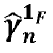
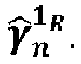
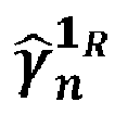
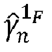
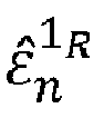
- the n th sample of these estimated activity signals are denoted by ⁇ ⁇ n 1 F and ⁇ ⁇ n 1 R respectively.
- Said signals are used for the computation of the probability of the flexible structure to be in a restricted-movement status (i.e. when the exogenous boundary conditions limit the movement of the flexible structure).
- the present obtained signals allow the computation of the probability of the flying boom to be coupled or in contact with the slipway of the receptacle of a receiver aircraft.
- these computed input signals are conditioned by means of notch filters, preferably parametric filters, to avoid interferences between elastic modes.
- estimations of the isolated first elastic mode excitation assuming free-movement and restricted-movement statuses are obtained by means of computation, respectively ⁇ ⁇ n 1 F and ⁇ ⁇ n 1 R .
- the method according to this first inventive concept further comprises:
- step d) Based on the outputs of step c), present step d) provides a smooth estimate of the amplitude of the estimated isolated free-movement and restricted-movement first elastic mode excitation signals, ⁇ ⁇ n 1 F and ⁇ ⁇ n 1 R by means of an amplitude demodulation technique.
- the method of the first inventive aspect comprises the following steps, based on recursive computations, which provides results on samples based on the results of the immediately previous sample.
- the method according to this first inventive concept further comprises:
- the estimated probability P n R obtained is that referred to the flexible structure being in a restricted-movement status.
- the method of the first inventive aspect provides the following result, in order to detect the physical status of the flexible structure.
- adequate values of p R and p F , in restricted-movement and free-movement status, respectively, are the following: p R ⁇ 0.75 0.95 , p F ⁇ 0.05 0.25 .
- the previous step provides a result for the detection of the physical status of the flexible structure, in order to check that the current filtering mode being active in the flight control laws (CLAWs) is the adequate filtering mode.
- CLAWs flight control laws
- the main advantage of the proposed first inventive aspect is that it does not require additional measurement sources or elements to detect the transitions from physical free-movement status to restricted-movement status of the flexible structure and vice versa, thus being capable of detecting conditions in which the filtering modes of the flight control laws (CLAWs) need to be configured according to the actual real physical status of the flexible structure.
- CLAWs flight control laws
- the filtering mode of the flight control laws is set by means of a binary discrete input signal M , being M n the n th sample of the M signal defined as:
- the flight control laws (CLAWs), and particularly the filtering modes of said flight control laws (CLAWs) which rule the filtering strategy applied to the feedback signals, are set according to a binary discrete input signal M , such that the two possible physical statuses of the flexible structure are defined.
- Said binary discrete input signal M can be linked to the Boolean signal R n to automatically set the proper filtering mode of the flight control laws (CLAWs) according to the detected physical status of the flexible structure defined by R n .
- CLAWs flight control laws
- the method further comprises the step g) of updating the flight control laws' (CLAWs) filtering mode already set as follows:
- the current status of the flexible structure is detected according to steps a) to f) of the method of the first inventive aspect.
- filters such as second order notch filters are adequate for the present conditioning.
- the present generic band-pass filter provides the estimated activity signals of step b) of the present method.
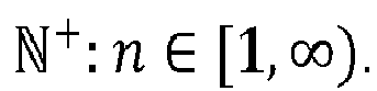
- step a) further comprises sampling a third discrete-time scalar signal L containing the measured shape of the flexible structure, being L n the n th sample of the L signal provided by a third active measurement source (C), this sampling being performed with a sample time ⁇ t, and the n th sample of a signal being n ⁇ N + : n ⁇ [ 1 , ⁇ ) .
- This additional signal L provides information related to the current shape and morphology of the flexible structure, which can modify its configuration over time, and thus its elastic characteristics.
- mapping functions ⁇ 1 F ( L n ) and ⁇ 1 R ( L n ) can be obtained using any of the following procedures:
- a second inventive aspect of the invention provides a computer program comprising a computer program code, which, when executed by a computer device, causes the computer device to carry out all the method steps of the first inventive aspect.
- the invention provides a system comprising a flexible structure and a computer device, the computer device being configured to apply a method for detecting a physical status of a flexible structure, said physical status being either free-movement or restricted-movement, according to the first inventive aspect.
- the physical status is detected by the method according to the first inventive aspect.
- the flexible structure is a flying boom so that the free-movement physical status corresponds to the free-air status of the flying boom, and the restricted-movement physical status corresponds to the flying boom status being coupled to or in contact with the slipway of a receptacle of a receiver aircraft.
- the present invention provides an aircraft comprising a system according to the third inventive aspect. More particularly, the aircraft is a tanker aircraft and the flexible structure of the system is a flying boom.
- the present invention firstly discloses a method for detecting the physical status, which can be a free-movement or restricted-movement status, of a flexible structure.
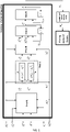
- Figure 1 shows a diagram with the steps of a particular embodiment of the present method to detect the physical status (free-movement, restricted movement) of a flexible structure.
- This flexible structure has time-varying elastic characteristics with a total number N ⁇ N + of elastic modes, wherein i is a generic elastic mode, i ⁇ N + : i ⁇ 1 N .
- the signals y A and y B contain the measured dynamics of the flexible structure.
- the n th sample L n of another discrete-time scalar signal L is further supplied to obtain in step b) the signals ⁇ ⁇ n 1 F and ⁇ ⁇ n 1 R .
- Said signal L contains the measured shape of the flexible structure.
- Both signals y A and y B and signal L are sampled in step a) (not shown in figure 1 ) with a sample time ⁇ t , and wherein the n th sample of each signal is n ⁇ N + : n ⁇ [ 1 , ⁇ ) .
- ⁇ ⁇ n 1 F ⁇ ⁇ 1 F L n
- ⁇ ⁇ n 1 R ⁇ ⁇ 1 R L n .
- the perfect cancellation parameters are obtained by estimations of the first elastic mode unitary displacement functions for free-movement status ⁇ 1 F ( x, L n ) and for restricted-movement status ⁇ 1 R ( x,L n ).
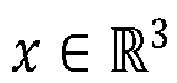
- x ⁇ R 3 is the 3D coordinate vector of a generic point of the flexible structure.
- K ⁇ n 1 F 1 1 ⁇ ⁇ 1 F x A L n / ⁇ 1 F x B L n
- K ⁇ n 1 R 1 1 ⁇ ⁇ 1 R x A L n / ⁇ 1 R x B L n .
- the location of the first A and second B sensor in the flexible structure are represented by the expression shown above x A and x B .
- the estimated isolated free-movement and restricted-movement first elastic mode excitation signals are obtained be means of a first and second notch filters.
- the NF F and NF R denotes the discrete transfer functions of the first and second notch filters.
- These notch filters are parametric notch-filters that are applied to signals ⁇ ⁇ n 1 F and ⁇ ⁇ n 1 R with respective notch-frequencies ⁇ ⁇ n 1 R and ⁇ ⁇ n 1 F .
- the discrete transfer function of the parametric first and second notch-filters in the z -1 plane is expressed by NF.
- step d) the amplitude ⁇ ⁇ ⁇ n 1 F ⁇ and ⁇ ⁇ ⁇ n 1 R ⁇ of the isolated elastic mode excitation signals ⁇ ⁇ n 1 F and ⁇ ⁇ n 1 R are estimated by amplitude demodulation.
- the estimated probability P n R of the flexible structure to be in a restricted-movement status is recursively computed according to step e).
- a discrete state Boolean signal R n is recursively computed at the n th sample as follows:
- p R is a predetermined restricted-movement probability parameter and must be greater than 0 and lower than 1; and p F is a predetermined free-movement probability parameter and must be greater or equal to 0 and lower or equal to 1.
- the flexible structure is controlled by flight control laws (CLAWs) that comprise specific filtering modes for free-movement or restricted-movement status.
- CLAWs flight control laws
- the filtering mode of the CLAWs is set by means of a binary discrete input signal M .
- M binary discrete input signal
- the present method comprises the step g) where the filtering mode is set as follows:
- FIG 2 shows a particular example of a flying boom (1) of a tanker aircraft, particularly a zoom of the tail cone area of a tanker aircraft with the flying boom (1) deployed.
- This flying boom (1) comprises two active measurement sources, which correspond to a first sensor (A) and a second sensor (B).
- the first sensor (A) is a ball joint angle sensor located on the gimballed attachment (2) of the flying boom (1) to the tanker aircraft; and the second sensor (B) is an Inertial Measurement Unit (IMU) that is located in the bulb (3) of the flying boom (1) close to the hinge of the control surfaces (4).
- IMU Inertial Measurement Unit
- the first sensor (A) provides a first discrete-time scalar signal y A and the second sensor (B) provides a second discrete-time scalar signal y B .
- Both signals contain the dynamics of the flying boom (1) measured at different locations; said dynamics defined wither by angular orientation, angular rates or angular accelerations of the flying boom (1).
- the elastic modes shapes and undamped elastic modes frequencies of the flying boom (1) flexible structure suffer large variations derived from fast changes in the exogenous boundary conditions acting on the nozzle. In this particular case of a flying boom (1), these changes in the exogenous boundary conditions occur during transitions from free-movement status to restricted-movement status of the flying boom (1) flexible structure and vice versa.
- signals y A and y A are sampled with a sample time ⁇ t so that y n A and y n B are the n th sample of the respective signal provided by the first (A) and second (B) sensor and n ⁇ N + : n ⁇ [ 1 , ⁇ ) .
- This flying boom (1) further comprises a third active measurement source corresponding to a third sensor (C).
- this third sensor (C) is a potentiometer located in the telescopic beam (5) which measures the length (L) of the beam section that is cantilevered and exposed to the air free stream.
- This third sensor (C) provides a third discrete-time scalar signal L which provides information related to the current shape and morphology of the flying boom (1), particularly, the length (L) of the telescopic beam (5) section that is cantilevered and exposed to the air free stream that changes its configuration over time with extension or retraction movements.
- the present method is able to detect the physical status of the flying boom (1), and thus, it is able to detect if there is any mismatch between the actual physical status of the flying boom (1) and the filtering mode of the flight control laws (CLAWs).
- CLAWs flight control laws
Landscapes
- Engineering & Computer Science (AREA)
- Aviation & Aerospace Engineering (AREA)
- Physics & Mathematics (AREA)
- General Physics & Mathematics (AREA)
- Fluid Mechanics (AREA)
- Testing Or Calibration Of Command Recording Devices (AREA)
- Measurement Of Mechanical Vibrations Or Ultrasonic Waves (AREA)
- Paper (AREA)
- Investigating Strength Of Materials By Application Of Mechanical Stress (AREA)
- Investigating Or Analyzing Materials By The Use Of Ultrasonic Waves (AREA)
- Control Of Position, Course, Altitude, Or Attitude Of Moving Bodies (AREA)
- Arrangements For Transmission Of Measured Signals (AREA)
Abstract
Description
- The present invention belongs to the field of flight control laws (CLAWs) used to control a flexible structure, for example an air to air refuelling flying boom system, specifically to a method for detecting the physical status determined by the exogenous boundary conditions acting on said flexible structure.
- The present invention is also related to a computer program which carries out the method for detecting the physical status of a flexible structure, as well as to a system and aircraft comprising such a flexible structure.
- Currently, an Air to Air Refuelling (AAR) flying boom system comprises a telescoping tube with flight control surfaces. Said telescoping tube, comprises a telescopic beam with the capacity to be extended telescopically to make the physical connection with the receptacle of a receiver aircraft, carrying out in this manner the transfer of fuel from the tanker aircraft to the receiver aircraft.
- For the specific case of the flying boom system, the air refuelling operator (ARO) needs to fly the boom and extend and insert the nozzle located at the end of the telescopic beam into the receiver Universal Aerial Refuelling Receptacle System Installation (UARRSI). Once the nozzle has made contact, latches in the UARRSI of the receiver aircraft are triggered and closed to ensure that the nozzle is properly locked during the fuel transfer.
- The flight control laws (CLAWs) of flying boom systems embodied on the aerial refuelling boom system itself have different and specific feedback filtering modes for "free-movement" (no contact) or "restricted-movement" (contact) physical status, denoted "free-flight" and "coupled" filtering modes respectively (CLAWs filtering modes).
- These CLAWs filtering modes are designed to eliminate the elastic modes components present in the feedback signals that contain the measured dynamics of the flexible structure.
- In general, the elastic modes characteristics of the flexible structure (elastic modes frequencies and elastic modes shapes) strongly depend on the exogenous boundary conditions acting on the flexible structure. The elastic modes in "free-movement" physical status are completely different from the elastic modes of the flexible structure when it is physically in "restricted-movement" or "coupled" condition, and thus a specific filtering mode for each condition is required in the flight control laws (CLAWs). Therefore, in order to have a well performing and smooth control during every phase of the refuelling operation, an automatic system is needed to detect the restricted-movement condition to commute from the "free-flight" filtering mode to the "coupled" filtering mode and vice versa.
- The need to identify the actual physical status of the mentioned flexible structure (which is determined by the exogenous boundary conditions) is therefore essential for aerial refuelling operations with a flying boom system. Failure to detect the actual physical status of the flying boom may lead to the unintentional activation of an inadequate filtering mode of the flight control laws (CLAWs), leading to handling qualities degradations or even unstable aeroservoelastic coupling phenomenon, i.e., divergent oscillatory loads that can ultimately cause the breakage of the flying boom structural components.
- The current state-of-the-art refers to a method to detect the physical status (free-movement or restricted-movement status) of the flying boom. This method is based on the generation and detection of a pulse signal generated when the induction coil of the receiver receptacle is aligned with the induction coil of the nozzle once the nozzle is properly mated. Once this electrical pulse is received and recognized by the flying boom, the flight control laws (CLAWs) filtering modes are switched from "free-flight" to "coupled" status, and vice versa, based on the connection or disconnection signal received.
- This method suffers from Filtering Mode Mismatch (FMM) drawbacks, that is, the flight control laws (CLAWs) might be in a filtering mode which is incoherent with the actual physical status of the flexible structure, the flying boom.
- The Filtering Mode Mismatch condition is triggered when one of the following events occurs:
- Nozzle cocking: The flight control laws (CLAWs) are in the "free-flight" filtering mode, and the flying boom's nozzle tip rests within the receiver's receptacle, but the boom is not properly seated in the receptacle. Thus, the structure movement is constrained due to a wrong alignment of the flying boom with the receiver receptacle whereas the flight control laws (CLAWs) filtering mode is not coherent with the mentioned physical constraint.
- Undetected "contact": The flight control laws (CLAWs) are in "free-flight" filtering mode and the boom nozzle is inside of the receptacle properly latched, but there has been a coil signal failure, i.e., failure to recognize the pulse generated by the induction coil, failure to generate the pulse from the induction coil, or latches have been jammed in a closed position, whilst the flight control laws (CLAWs) have transitioned to "free-flight" filtering mode, even though the boom nozzle remains latched to the receiver receptacle.
- Undetected "float-out": The flight control laws (CLAWs) are in "coupled" filtering mode, but the structure is in a "free-movement" physical status, due to the fact that the boom nozzle has exited the receiver's receptacle as a result of an un-latched condition, generating a boom "float-out".
- Such mismatches may cause structural damage to the mentioned flexible structure, particularly the flying boom structure, as the flight control laws (CLAWs) are using a filtering mode for the controller's feedback signals which does not correspond with the actual physical status of the flexible structure, and thus, the flying boom does not behave as it should as its flexible structure is being incorrectly controlled by the flight control laws (CLAWs).
- The present invention provides a method of detection of the physical status of a flexible structure that shall be applied on an air to air refuelling boom system during a refuelling operation in the event of failure to transmit or to recognize the coil signal used during such refuelling operation. That is, the method of detection of the physical status of a flexible structure provides a result which allows knowing if the actual physical status of said flexible structure is coherent or not with the filtering mode of the flight control laws. Thus, the present invention solves the different failure casuistry related to Filtering Mode Mismatch conditions, rendering a more robust flight control system.
- The present invention provides an alternative solution for the aforementioned problems, by a method for detecting the physical status of a flexible structure according to
claim 1, a computer program according to claim 11, a system according to claim 12 and an aircraft according to claim 14. In dependent claims, preferred embodiments of the invention are defined. - In a first inventive aspect, the invention provides a method for detecting a physical status of a flexible structure, said status being either free-movement or restricted-movement, the flexible structure having time-varying elastic characteristics, with a total number


- Throughout all this document, a flexible structure will be understood as a structure which is defined by means of time-varying elastic characteristics, said characteristics depending on the geometry and shape of the flexible structure itself. Thus, the flexible structure is characterized by fast time-varying geometries and exogenous boundary conditions that can suffer discrete changes, as well as elastic variable characteristics.
- That is, for example, when a structure is able to change its length along time, the elastic characteristics vary according to the current value of such length.
- Such flexible structure is controlled by means of flight control laws (CLAWs), these CLAWs comprising specific filtering modes for "free-movement" and for "restricted-movement" physical status of the flexible structure.
- These specific filtering modes, which are applied to the feedback control signals containing the measured dynamics of the flexible structure, are enabled or disabled according to the estimated physical status of the flexible structure.
- Thus, in a particular embodiment, the present method of detection shall be applied on an air to air refuelling boom system as flexible structure, during a refuelling operation, in the event that the coil signal normally used during such refuelling operation fails to be generated, transmitted or recognized.
- That is, the method of detection of the physical status of a flexible structure provides a result which allows knowing if the physical status of said flexible structure is incoherent with the flight control laws' (CLAWs) filtering mode.
- Particularly, throughout all this document, two different physical statuses for the flexible structure will be defined, namely:
- Free-movement status: the flexible structure has no constraints on one of its ends, as it is not coupled to any additional structure.
- Restricted-movement status: the flexible structure is coupled with an additional structure, and thus its movement is conditioned by the restrictions imposed by said coupling (exogenous boundary conditions and holonomic constraints).
- The flight control laws (CLAWs) filtering modes are defined according to the aforementioned statuses, such that there are filtering modes which are designed to be used when the structure is in the free-movement status, and filtering modes which are designed to be used when the structure is in the restricted-movement status.
- The method of the first inventive aspect comprises several steps, namely:
- a) sampling a first and a second discrete-time scalar signals yA and yB containing the measured dynamics of the flexible structure, being


- The discrete-time signals, present in step a) of the method, measure the dynamics of a flexible structure which comprises a total number N of elastic modes and, advantageously, these signals are obtained by means of only two active measurement sources, e.g., sensors, namely the first (A) and second (B) active measurement sources.
- These active measurement sources are located along the flexible structure and indistinctly provide discrete measures of the flexible structure dynamics. These active measurement sources can be angular orientation measurement units or angular rate measurement units, such as angular orientation sensors or angular rate sensors.
- The method for detecting a physical status of a flexible structure further comprises the step of:
- b) obtaining from the first and second


- first elastic mode (i = 1) estimated activity signal

- first elastic mode (i = 1) estimated activity signal

- first elastic mode (i = 1) estimated activity signal
- Once the mentioned measurements have been performed, and the first and second


- Said signals are used for the computation of the probability of the flexible structure to be in a restricted-movement status (i.e. when the exogenous boundary conditions limit the movement of the flexible structure). For example, when the flexible structure is a flying boom of a tanker aircraft, the present obtained signals allow the computation of the probability of the flying boom to be coupled or in contact with the slipway of the receptacle of a receiver aircraft.
- c) obtaining the estimated isolated free-movement and restricted-movement first elastic mode excitation signals,


- According to step c) of the method, these computed input signals are conditioned by means of notch filters, preferably parametric filters, to avoid interferences between elastic modes. Said notch filters are designed such that the first elastic mode ( i = 1) estimated activity signals


-

-

- Outputs obtained from step b) are conditioned using the digital notch filters introduced above in order to eliminate the cross elastic mode component residues which might be still present in the first elastic mode (i = 1) estimated activity signals


- As a result, estimations of the isolated first elastic mode excitation assuming free-movement and restricted-movement statuses are obtained by means of computation, respectively


- Additionally, the method according to this first inventive concept further comprises:
- d) estimating the amplitude


- Based on the outputs of step c), present step d) provides a smooth estimate of the amplitude of the estimated isolated free-movement and restricted-movement first elastic mode excitation signals,


- In a particular embodiment, this amplitude demodulation of step d) is performed with a third parametric notch-filter applied to the signal


- Once the estimated amplitude of the estimated isolated free-movement and restricted-movement first elastic mode excitation signals,


- Moreover, the method according to this first inventive concept further comprises:
- e) recursively computing the estimated probability


- According to the present step, the estimated probability

- Finally, the method of the first inventive aspect provides the following result, in order to detect the physical status of the flexible structure.
- f) detecting the physical status of the flexible structure by recursively computing a discrete state Boolean signal Rn at the nth sample, wherein Rn-1 is a previous value of the discrete state Boolean signal at the (n - 1) th sample, wherein when n = 1, being step g) of the method applied for the first time, then Rn-1 = false, being the flexible structure in free-movement status, and the discrete state Boolean signal Rn being recursively computed as follows:
- if

- if

- if
- In a preferred embodiment, adequate values of pR and pF, in restricted-movement and free-movement status, respectively, are the following:


- More preferably, the values of the mentioned parameters, in restricted-movement and free-movement status, respectively, are:
pR = 0.90,
pF = 0.10. - The previous step provides a result for the detection of the physical status of the flexible structure, in order to check that the current filtering mode being active in the flight control laws (CLAWs) is the adequate filtering mode.
- That is, the main advantage of the proposed first inventive aspect is that it does not require additional measurement sources or elements to detect the transitions from physical free-movement status to restricted-movement status of the flexible structure and vice versa, thus being capable of detecting conditions in which the filtering modes of the flight control laws (CLAWs) need to be configured according to the actual real physical status of the flexible structure.
- This results in a high efficient method, which additionally simplifies the configuration of the system which comprises the flexible structure to be monitored. For example, when the flexible structure is a flying boom, the system is simplified as it does not require a pulse signal generated by the nozzle coil or any additional sensors.
- In a particular embodiment, the filtering mode of the flight control laws (CLAWs) is set by means of a binary discrete input signal M, being M n the n th sample of the M signal defined as:
- Mn = 0 sets the filtering mode to free-movement filtering mode, or
- Mn = 1 sets the filtering mode to restricted-movement filtering mode.
- That is, the flight control laws (CLAWs), and particularly the filtering modes of said flight control laws (CLAWs) which rule the filtering strategy applied to the feedback signals, are set according to a binary discrete input signal M , such that the two possible physical statuses of the flexible structure are defined.
- Said binary discrete input signal M can be linked to the Boolean signal Rn to automatically set the proper filtering mode of the flight control laws (CLAWs) according to the detected physical status of the flexible structure defined by Rn .
- In a more particular embodiment, the method further comprises the step g) of updating the flight control laws' (CLAWs) filtering mode already set as follows:
- If Rn = true, the filtering mode is switched to the restricted-movement filtering mode by setting the nth sample of the input signal Mn to one (Mn = 1),
- If Rn = false, the filtering mode is switched to the free-movement filtering mode by setting the nth sample of the input signal Mn to zero (Mn = 0).
- Thus, according to the present step, the current status of the flexible structure, either free-movement or restricted-movement, is detected according to steps a) to f) of the method of the first inventive aspect.
- In case of mismatch between such detected physical status and the filtering mode of the flight control laws (CLAWs) being active, an automatic switch to the proper filtering mode is made, so as to grant that the filtering of the feedback signals used in the controllers of the flight control laws is done appropriately and coherently according to the current detected physical status of said flexible status, thus avoiding any problem related with the control of the flexible structure that might appear in Filtering Mode Mismatch (FMM) conditions.
- In a particular embodiment, the first and second notch-filters NFF and NFR present in step c) are parametric notch-filters applied to signals


- In a particular embodiment, filters such as second order notch filters are adequate for the present conditioning.
- In a more particular embodiment, the nth sample of the first elastic mode (i = 1) estimated activity signals γ̂ 1 F and γ̂ 1 R , referred by


- The present generic band-pass filter provides the estimated activity signals of step b) of the present method.
- In a particular embodiment, step a) further comprises sampling a third discrete-time scalar signal L containing the measured shape of the flexible structure, being Ln the nth sample of the L signal provided by a third active measurement source (C), this sampling being performed with a sample time Δt, and the nth sample of a signal being

- This additional signal L provides information related to the current shape and morphology of the flexible structure, which can modify its configuration over time, and thus its elastic characteristics.
- In a particular embodiment, the nth sample of the first elastic mode (i = 1) estimated frequencies in free-movement status and restricted-movement status, correspondent with


- These mapping functions, ω̂ 1 F (Ln ) and ω̂ 1 R (Ln ), provide information about the evolution of the frequency of the first elastic mode (i = 1) for free-movement status


- Mapping functions ω̂ 1 F (Ln ) and ω̂ 1 R (Ln ) can be obtained using any of the following procedures:
- Aeroelastic analyses based on doublet lattice and finite elements methods and tools,
- Ground vibration tests, or
- Real-time frequency estimators (i.e. adaptive notch filter estimators).
- In a particular embodiment, the perfect cancellation parameters


 .
.
- The relationship between the unitary displacement functions at xA and xB (representing the location of the active measurement sources A and B respectively in the elastic structure), ϕ 1 F (xA,Ln )/ϕ 1 F (xB,Ln ) and ϕ 1 R (xA,Ln )/ ϕ 1 R (xB ,Ln ), can be obtained either by:
- Aeroelastic analyses based on doublet lattice and finite elements methods and tools, or
- Ground vibration tests, or
- Real-time elastic mode unitary displacement estimators.
- Once the relationship between the unitary displacement functions ϕ 1 F (xA ,Ln )/ ϕ 1 F (xB,Ln ) and ϕ 1 R (xA,Ln )/ϕ 1 R (xB,Ln ) have been obtained by any of the previous means, the perfect cancellation parameters can be computed as follows:


- A second inventive aspect of the invention provides a computer program comprising a computer program code, which, when executed by a computer device, causes the computer device to carry out all the method steps of the first inventive aspect.
- This allows the performance by means of any computer device of the present method for detecting the physical status of a flexible structure.
- In a third inventive aspect, the invention provides a system comprising a flexible structure and a computer device, the computer device being configured to apply a method for detecting a physical status of a flexible structure, said physical status being either free-movement or restricted-movement, according to the first inventive aspect. The physical status is detected by the method according to the first inventive aspect.
- In a particular embodiment, the flexible structure is a flying boom so that the free-movement physical status corresponds to the free-air status of the flying boom, and the restricted-movement physical status corresponds to the flying boom status being coupled to or in contact with the slipway of a receptacle of a receiver aircraft.
- In a fourth inventive aspect, the present invention provides an aircraft comprising a system according to the third inventive aspect. More particularly, the aircraft is a tanker aircraft and the flexible structure of the system is a flying boom.
- All the features described in this specification (including the claims, description and drawings) and/or all the steps of the described method can be combined in any combination, with the exception of combinations of such mutually exclusive features and/or steps.
- These and other characteristics and advantages of the invention will become clearly understood in view of the detailed description of the invention which becomes apparent from a preferred embodiment of the invention, given just as an example and not being limited thereto, with reference to the drawings.
-
Figure 1 This figure shows a diagram with the steps of a method for detecting the physical status of a flexible structure according to an embodiment of the present invention. -
Figure 2 This figure shows a particular embodiment of a flying boom of a tanker aircraft on which the method for detecting the physical status of this flying boom of the present invention is applied. - The present invention firstly discloses a method for detecting the physical status, which can be a free-movement or restricted-movement status, of a flexible structure.
-
Figure 1 shows a diagram with the steps of a particular embodiment of the present method to detect the physical status (free-movement, restricted movement) of a flexible structure. This flexible structure has time-varying elastic characteristics with a total number

- As it can be observed, the nth sample


- Moreover, the nth sample Ln of another discrete-time scalar signal L, from a third sensor (C), is further supplied to obtain in step b) the signals

- Both signals yA and yB and signal L are sampled in step a) (not shown in
figure 1 ) with a sample time Δ t, and wherein the nth sample of each signal is n ∈
- Furthermore, the notch-frequencies of free-movement and restricted-movement,


- In a particular example, step b) further comprises computing:


- BP is the discrete transfer function of a band-pass filter whit a parametric band-pass frequency.


- These perfect cancellation parameters are computed as follows:


- The location of the first A and second B sensor in the flexible structure are represented by the expression shown above xA and xB.
- Once the first elastic mode ( i = 1) estimated activity signals



- The NFF and NFR denotes the discrete transfer functions of the first and second notch filters. These notch filters are parametric notch-filters that are applied to signals


- The discrete transfer function of the parametric first and second notch-filters in the z -1 plane is expressed by NF.
- The method continues with step d) where the amplitude
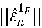


- Once the amplitude



- For the above estimated probability, λ is an update gain constant with λ > 0, and


- For detecting if the flexible structure is in a free-movement status or restricted-movement status in step f), a discrete state Boolean signal Rn is recursively computed at the nth sample as follows:
- if

- if

- R n-1 is a previous value of the discrete state Boolean signal at the ( n - 1) th sample, and when n = 1, it is the first time that the step f) of the method is applied, and therefore, R n-1 = false. This implies that the flexible structure is in a free-movement status.
- p R is a predetermined restricted-movement probability parameter and must be greater than 0 and lower than 1; and p F is a predetermined free-movement probability parameter and must be greater or equal to 0 and lower or equal to 1.
- In a particular example, pR ∈ [0.75,0.95] and pF ∈ [0.05,0.25],
- Therefore, when Rn = false, then the flexible structure is in a free-movement status; and when Rn = true, then the flexible structure is in a restricted movement.
- The flexible structure is controlled by flight control laws (CLAWs) that comprise specific filtering modes for free-movement or restricted-movement status. Particularly, the filtering mode of the CLAWs is set by means of a binary discrete input signal M . The n th sample M n of the M signal is defined as:
- Mn = 0 sets the filtering mode to free-movement filtering mode, or
- Mn = 1 sets the filtering mode to restricted-movement filtering mode.
- Furthermore, the present method comprises the step g) where the filtering mode is set as follows:
- f Rn = true, the filtering mode is switched to the restricted-movement filtering mode by setting the nth sample of the input signal Mn to one (Mn = 1),
- If Rn = false, the filtering mode is switched to the free-movement filtering mode by setting the nth sample of the input signal Mn to zero (Mn = 0).
-
Figure 2 shows a particular example of a flying boom (1) of a tanker aircraft, particularly a zoom of the tail cone area of a tanker aircraft with the flying boom (1) deployed. This flying boom (1) comprises two active measurement sources, which correspond to a first sensor (A) and a second sensor (B). In particular, the first sensor (A) is a ball joint angle sensor located on the gimballed attachment (2) of the flying boom (1) to the tanker aircraft; and the second sensor (B) is an Inertial Measurement Unit (IMU) that is located in the bulb (3) of the flying boom (1) close to the hinge of the control surfaces (4). - The first sensor (A) provides a first discrete-time scalar signal yA and the second sensor (B) provides a second discrete-time scalar signal yB . Both signals contain the dynamics of the flying boom (1) measured at different locations; said dynamics defined wither by angular orientation, angular rates or angular accelerations of the flying boom (1).
- The elastic modes shapes and undamped elastic modes frequencies of the flying boom (1) flexible structure suffer large variations derived from fast changes in the exogenous boundary conditions acting on the nozzle. In this particular case of a flying boom (1), these changes in the exogenous boundary conditions occur during transitions from free-movement status to restricted-movement status of the flying boom (1) flexible structure and vice versa.
- For detecting the physical status of the flying boom (1) according to the present method, signals yA and yA are sampled with a sample time Δ t so that


- This flying boom (1) further comprises a third active measurement source corresponding to a third sensor (C). In particular, this third sensor (C) is a potentiometer located in the telescopic beam (5) which measures the length (L) of the beam section that is cantilevered and exposed to the air free stream.
- This third sensor (C) provides a third discrete-time scalar signal L which provides information related to the current shape and morphology of the flying boom (1), particularly, the length (L) of the telescopic beam (5) section that is cantilevered and exposed to the air free stream that changes its configuration over time with extension or retraction movements.
- From the signals measured by at least the first (A), the second (B) and the third (C) sensors arranged along the flying boom (1) structure, the present method is able to detect the physical status of the flying boom (1), and thus, it is able to detect if there is any mismatch between the actual physical status of the flying boom (1) and the filtering mode of the flight control laws (CLAWs).
Claims (14)
- Method for detecting a physical status of a flexible structure, said status being either free-movement or restricted-movement, the flexible structure having time-varying elastic characteristics, with a total number

 a) sampling a first and a second discrete-time scalar signals yA and yB containing the measured dynamics of the flexible structure, being

 b) obtaining from the first and second
 • first elastic mode (i = 1) estimated activity signal
 • first elastic mode (i = 1) estimated activity signal
 c) obtaining the estimated isolated free-movement and restricted-movement first elastic mode excitation signals,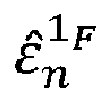


 d) estimating the amplitude


 e) recursively computing the estimated probability


 f) detecting the physical status of the flexible structure by recursively computing a discrete state Boolean signal Rn at the nth sample, wherein Rn-1 is a previous value of the discrete state Boolean signal at the (n - 1) th sample, wherein when n = 1, being step f) of the method applied for the first time, then Rn-1 = false, being the flexible structure in free-movement status,
and the discrete state Boolean signal Rn being recursively computed as follows:• if • ifwherein 0 ≤ pR ≤ 1 corresponds to a predetermined restricted-movement probability parameter, and 0 ≤ pF ≤ 1 corresponds to a predetermined free-movement probability parameter, and
wherein the detected physical status of the flexible structure corresponds to free-movement status if Rn = false, and to restricted-movement status if Rn = true. - Method according to claim 1, wherein the filtering mode of the flight control laws (CLAWs) is set by means of a binary discrete input signal M, being Mn the nth sample of the M signal defined as:• Mn = 0 sets the filtering mode to free-movement filtering mode, or• Mn = 1 sets the filtering mode to restricted-movement filtering mode.
- Method according to claim 2 further comprising the step g) of updating the filtering mode already set as follows:• If Rn = true, the filtering mode is switched to the restricted-movement filtering mode by setting the nth sample of the input signal Mn to one (Mn = 1),• If Rn = false, the filtering mode is switched to the free-movement filtering mode by setting the nth sample of the input signal Mn to zero (Mn = 0).
- Method according to any of previous claims wherein the first and second notch-filters NFF and NFR present in step c) are parametric notch-filters applied to signals


- Method according to any of previous claims, wherein the amplitude demodulation of step d) is performed with a third parametric notch-filter applied to the signal


- Method according to any of the previous claims, wherein the restricted-movement and free-movement probability parameters pR and pF of step f) are pR ∈ [0.75,0.95] and pF ∈ [0.05,0.25].
- Method according to any of the previous claims, wherein step a) further comprises sampling a third discrete-time scalar signal L containing the measured shape of the flexible structure, being Ln the nth sample of the L signal provided by a third active measurement source (C), this sampling being performed with a sample time Δt, and the nth sample of a signal being n ∈
- Method according to any of claims 4 to 7, wherein the nth sample of the estimated first elastic mode (i = 1) activity signal


- Method according any of claims 4 to 8, and claim 7, wherein the notch-frequencies at the nth sample, correspondent with the free-movement and restricted-movement status,


 • Aeroelastic analyses based on doublet lattice and finite elements methods and tools,• Ground vibration tests, or• Real-time frequency estimators (i.e. adaptive notch filter estimators).
 - Method according to any of claims 4 to 9, and claim 7, wherein the perfect cancellation parameters


 • Aeroelastic analyses based on doublet lattice and finite elements methods and tools, or• Ground vibration tests, or• Real-time elastic mode unitary displacement estimators.
 - A computer program comprising a computer program code, which, when executed by a computer device, causes the computer device to carry out all the method steps of any of the claims 1 to 10.
- System comprising a flexible structure and a computer device, the computer device being configured to apply a method for computing the probability of a flexible structure to be in a physical status, said physical status being either free-movement or restricted-movement, according to any of claims 1 to 10.
- System according to claim 12, wherein the flexible structure is a flying boom (1) so that the free-movement physical status corresponds to the free-air status of the flying boom (1), and the restricted-movement physical status corresponds to the coupled status of the flying boom (1) with a receiver aircraft.
- Aircraft comprising a system according to any of claims 12 or 13.
Priority Applications (3)
| Application Number | Priority Date | Filing Date | Title |
|---|---|---|---|
| ES21382211T ES2951197T3 (en) | 2021-03-17 | 2021-03-17 | Method for detecting a physical state of a flexible structure |
| EP21382211.7A EP4060309B1 (en) | 2021-03-17 | 2021-03-17 | Method for detecting a physical status of a flexible structure |
| US17/694,746 US12091186B2 (en) | 2021-03-17 | 2022-03-15 | Method for detecting a physical status of a flexible structure |
Applications Claiming Priority (1)
| Application Number | Priority Date | Filing Date | Title |
|---|---|---|---|
| EP21382211.7A EP4060309B1 (en) | 2021-03-17 | 2021-03-17 | Method for detecting a physical status of a flexible structure |
Publications (2)
| Publication Number | Publication Date |
|---|---|
| EP4060309A1 true EP4060309A1 (en) | 2022-09-21 |
| EP4060309B1 EP4060309B1 (en) | 2023-05-10 |
Family
ID=75223278
Family Applications (1)
| Application Number | Title | Priority Date | Filing Date |
|---|---|---|---|
| EP21382211.7A Active EP4060309B1 (en) | 2021-03-17 | 2021-03-17 | Method for detecting a physical status of a flexible structure |
Country Status (3)
| Country | Link |
|---|---|
| US (1) | US12091186B2 (en) |
| EP (1) | EP4060309B1 (en) |
| ES (1) | ES2951197T3 (en) |
Cited By (1)
| Publication number | Priority date | Publication date | Assignee | Title |
|---|---|---|---|---|
| CN115541168A (en) * | 2022-11-28 | 2022-12-30 | 中国空气动力研究与发展中心低速空气动力研究所 | Device and method for simulating free flight of wind tunnel in air refueling docking of double machines |
Families Citing this family (2)
| Publication number | Priority date | Publication date | Assignee | Title |
|---|---|---|---|---|
| US12503250B2 (en) * | 2023-01-31 | 2025-12-23 | The Boeing Company | Systems and method to determine connection of a boom with a receiver aircraft |
| CN120121045B (en) * | 2025-05-08 | 2025-07-11 | 苏州大学 | MEMS gyroscope zero-bias temperature drift inhibition method and system and MEMS gyroscope |
Citations (2)
| Publication number | Priority date | Publication date | Assignee | Title |
|---|---|---|---|---|
| EP3088304A1 (en) * | 2015-04-27 | 2016-11-02 | Airbus Defence and Space, S.A. | Contact detecting system and method for air refueling tanker equipped with air refueling boom system |
| EP3299790A1 (en) * | 2016-09-23 | 2018-03-28 | Airbus Defence and Space, S.A.U. | Method for adaptively cancelling in real time elastic modes in discrete-time signals |
-
2021
- 2021-03-17 ES ES21382211T patent/ES2951197T3/en active Active
- 2021-03-17 EP EP21382211.7A patent/EP4060309B1/en active Active
-
2022
- 2022-03-15 US US17/694,746 patent/US12091186B2/en active Active
Patent Citations (2)
| Publication number | Priority date | Publication date | Assignee | Title |
|---|---|---|---|---|
| EP3088304A1 (en) * | 2015-04-27 | 2016-11-02 | Airbus Defence and Space, S.A. | Contact detecting system and method for air refueling tanker equipped with air refueling boom system |
| EP3299790A1 (en) * | 2016-09-23 | 2018-03-28 | Airbus Defence and Space, S.A.U. | Method for adaptively cancelling in real time elastic modes in discrete-time signals |
Non-Patent Citations (3)
| Title |
|---|
| LOZANO F ARÉVALO ET AL: "AEROELASTIC ROLE IN THE ROAD TO A FULLY AUTOMATED REFUELLING SYSTEM", 13 June 2019 (2019-06-13), XP055837260, Retrieved from the Internet <URL:https://www.asdjournal.org/public/Proceedings/IFASD_2019/IFASD-2019-048.pdf> [retrieved on 20210902] * |
| SALEHI PANIAGUA K ET AL: "Aeroelastic analysis of an air-to-air refueling hose-drogue system through an efficient novel mathematical model", JOURNAL OF FLUIDS AND STRUCTURES, ACADEMIC PRESS, AMSTERDAM, NL, vol. 100, 19 December 2020 (2020-12-19), XP086439987, ISSN: 0889-9746, [retrieved on 20201219], DOI: 10.1016/J.JFLUIDSTRUCTS.2020.103164 * |
| XIE YANGMIN ET AL: "Deployment process control of space masts via iterative learning control", THE 27TH CHINESE CONTROL AND DECISION CONFERENCE (2015 CCDC), IEEE, 23 May 2015 (2015-05-23), pages 1026 - 1031, XP033178169, DOI: 10.1109/CCDC.2015.7162068 * |
Cited By (1)
| Publication number | Priority date | Publication date | Assignee | Title |
|---|---|---|---|---|
| CN115541168A (en) * | 2022-11-28 | 2022-12-30 | 中国空气动力研究与发展中心低速空气动力研究所 | Device and method for simulating free flight of wind tunnel in air refueling docking of double machines |
Also Published As
| Publication number | Publication date |
|---|---|
| ES2951197T3 (en) | 2023-10-18 |
| US12091186B2 (en) | 2024-09-17 |
| US20220297849A1 (en) | 2022-09-22 |
| EP4060309B1 (en) | 2023-05-10 |
Similar Documents
| Publication | Publication Date | Title |
|---|---|---|
| US12091186B2 (en) | Method for detecting a physical status of a flexible structure | |
| KR20210129843A (en) | Method and Apparatus for Monitoring Fault of Unmanned Aerial Vehicle | |
| CN111666891B (en) | Method and device for estimating obstacle motion state | |
| EP4220086A1 (en) | Combined navigation system initialization method and apparatus, medium, and electronic device | |
| EP4053020A1 (en) | Autonomous maneuver generation to mate connectors | |
| US9587969B2 (en) | Automatic identification of sensors | |
| US8234037B2 (en) | Method and device for detecting oscillatory failures related to a servocontrol subsystem of an aircraft control surface | |
| D'Amato et al. | Fault tolerant low cost IMUS for UAVs | |
| CN110440799A (en) | A kind of attitude angle measurement emerging system and method based on gyroscope and accelerometer | |
| US12528193B2 (en) | Robot calibration method, robot and computer-readable storage medium | |
| US20180088000A1 (en) | Method for adaptively cancelling in real time elastic modes in discrete-time signals | |
| CN110703205A (en) | Ultrashort baseline positioning method based on adaptive unscented Kalman filtering | |
| CN107577238A (en) | The height control method of unmanned plane barometer dealing of abnormal data based on UKF | |
| CN113438615A (en) | Positioning method and device | |
| CN113447028A (en) | Unmanned aerial vehicle's inertial navigation system and unmanned aerial vehicle | |
| CN111486840A (en) | Robot positioning method, device, robot and readable storage medium | |
| US20100156697A1 (en) | Quantity smoother | |
| US7933725B2 (en) | Using sensor spectral energy to detect and/or isolate sensor faults | |
| JP5592394B2 (en) | Automatic reduction of the force applied to the refueling boom | |
| JP5175641B2 (en) | Communication system disconnection detection apparatus and communication system | |
| US8704681B2 (en) | Arrangement and method for cross-monitoring of data | |
| CN111198774B (en) | Unmanned vehicle simulation anomaly tracking method, device, equipment and computer readable medium | |
| CN115061493A (en) | Unmanned aerial vehicle automatic safe driving system and method and unmanned aerial vehicle | |
| EP3850374B1 (en) | System and method for determining accelerometer orientation | |
| CN111596086A (en) | Obstacle speed estimation method and device and electronic equipment |
Legal Events
| Date | Code | Title | Description |
|---|---|---|---|
| PUAI | Public reference made under article 153(3) epc to a published international application that has entered the european phase |
Free format text: ORIGINAL CODE: 0009012 |
|
| STAA | Information on the status of an ep patent application or granted ep patent |
Free format text: STATUS: THE APPLICATION HAS BEEN PUBLISHED |
|
| AK | Designated contracting states |
Kind code of ref document: A1 Designated state(s): AL AT BE BG CH CY CZ DE DK EE ES FI FR GB GR HR HU IE IS IT LI LT LU LV MC MK MT NL NO PL PT RO RS SE SI SK SM TR |
|
| STAA | Information on the status of an ep patent application or granted ep patent |
Free format text: STATUS: REQUEST FOR EXAMINATION WAS MADE |
|
| 17P | Request for examination filed |
Effective date: 20221019 |
|
| RBV | Designated contracting states (corrected) |
Designated state(s): AL AT BE BG CH CY CZ DE DK EE ES FI FR GB GR HR HU IE IS IT LI LT LU LV MC MK MT NL NO PL PT RO RS SE SI SK SM TR |
|
| GRAP | Despatch of communication of intention to grant a patent |
Free format text: ORIGINAL CODE: EPIDOSNIGR1 |
|
| STAA | Information on the status of an ep patent application or granted ep patent |
Free format text: STATUS: GRANT OF PATENT IS INTENDED |
|
| INTG | Intention to grant announced |
Effective date: 20221208 |
|
| GRAS | Grant fee paid |
Free format text: ORIGINAL CODE: EPIDOSNIGR3 |
|
| GRAA | (expected) grant |
Free format text: ORIGINAL CODE: 0009210 |
|
| STAA | Information on the status of an ep patent application or granted ep patent |
Free format text: STATUS: THE PATENT HAS BEEN GRANTED |
|
| AK | Designated contracting states |
Kind code of ref document: B1 Designated state(s): AL AT BE BG CH CY CZ DE DK EE ES FI FR GB GR HR HU IE IS IT LI LT LU LV MC MK MT NL NO PL PT RO RS SE SI SK SM TR |
|
| REG | Reference to a national code |
Ref country code: GB Ref legal event code: FG4D |
|
| REG | Reference to a national code |
Ref country code: AT Ref legal event code: REF Ref document number: 1567129 Country of ref document: AT Kind code of ref document: T Effective date: 20230515 Ref country code: CH Ref legal event code: EP |
|
| REG | Reference to a national code |
Ref country code: DE Ref legal event code: R096 Ref document number: 602021002344 Country of ref document: DE |
|
| REG | Reference to a national code |
Ref country code: IE Ref legal event code: FG4D |
|
| REG | Reference to a national code |
Ref country code: LT Ref legal event code: MG9D |
|
| REG | Reference to a national code |
Ref country code: NL Ref legal event code: MP Effective date: 20230510 |
|
| REG | Reference to a national code |
Ref country code: AT Ref legal event code: MK05 Ref document number: 1567129 Country of ref document: AT Kind code of ref document: T Effective date: 20230510 |
|
| REG | Reference to a national code |
Ref country code: ES Ref legal event code: FG2A Ref document number: 2951197 Country of ref document: ES Kind code of ref document: T3 Effective date: 20231018 |
|
| PG25 | Lapsed in a contracting state [announced via postgrant information from national office to epo] |
Ref country code: SE Free format text: LAPSE BECAUSE OF FAILURE TO SUBMIT A TRANSLATION OF THE DESCRIPTION OR TO PAY THE FEE WITHIN THE PRESCRIBED TIME-LIMIT Effective date: 20230510 Ref country code: PT Free format text: LAPSE BECAUSE OF FAILURE TO SUBMIT A TRANSLATION OF THE DESCRIPTION OR TO PAY THE FEE WITHIN THE PRESCRIBED TIME-LIMIT Effective date: 20230911 Ref country code: NO Free format text: LAPSE BECAUSE OF FAILURE TO SUBMIT A TRANSLATION OF THE DESCRIPTION OR TO PAY THE FEE WITHIN THE PRESCRIBED TIME-LIMIT Effective date: 20230810 Ref country code: NL Free format text: LAPSE BECAUSE OF FAILURE TO SUBMIT A TRANSLATION OF THE DESCRIPTION OR TO PAY THE FEE WITHIN THE PRESCRIBED TIME-LIMIT Effective date: 20230510 Ref country code: AT Free format text: LAPSE BECAUSE OF FAILURE TO SUBMIT A TRANSLATION OF THE DESCRIPTION OR TO PAY THE FEE WITHIN THE PRESCRIBED TIME-LIMIT Effective date: 20230510 |
|
| PG25 | Lapsed in a contracting state [announced via postgrant information from national office to epo] |
Ref country code: RS Free format text: LAPSE BECAUSE OF FAILURE TO SUBMIT A TRANSLATION OF THE DESCRIPTION OR TO PAY THE FEE WITHIN THE PRESCRIBED TIME-LIMIT Effective date: 20230510 Ref country code: PL Free format text: LAPSE BECAUSE OF FAILURE TO SUBMIT A TRANSLATION OF THE DESCRIPTION OR TO PAY THE FEE WITHIN THE PRESCRIBED TIME-LIMIT Effective date: 20230510 Ref country code: LV Free format text: LAPSE BECAUSE OF FAILURE TO SUBMIT A TRANSLATION OF THE DESCRIPTION OR TO PAY THE FEE WITHIN THE PRESCRIBED TIME-LIMIT Effective date: 20230510 Ref country code: LT Free format text: LAPSE BECAUSE OF FAILURE TO SUBMIT A TRANSLATION OF THE DESCRIPTION OR TO PAY THE FEE WITHIN THE PRESCRIBED TIME-LIMIT Effective date: 20230510 Ref country code: IS Free format text: LAPSE BECAUSE OF FAILURE TO SUBMIT A TRANSLATION OF THE DESCRIPTION OR TO PAY THE FEE WITHIN THE PRESCRIBED TIME-LIMIT Effective date: 20230910 Ref country code: HR Free format text: LAPSE BECAUSE OF FAILURE TO SUBMIT A TRANSLATION OF THE DESCRIPTION OR TO PAY THE FEE WITHIN THE PRESCRIBED TIME-LIMIT Effective date: 20230510 Ref country code: GR Free format text: LAPSE BECAUSE OF FAILURE TO SUBMIT A TRANSLATION OF THE DESCRIPTION OR TO PAY THE FEE WITHIN THE PRESCRIBED TIME-LIMIT Effective date: 20230811 |
|
| PG25 | Lapsed in a contracting state [announced via postgrant information from national office to epo] |
Ref country code: FI Free format text: LAPSE BECAUSE OF FAILURE TO SUBMIT A TRANSLATION OF THE DESCRIPTION OR TO PAY THE FEE WITHIN THE PRESCRIBED TIME-LIMIT Effective date: 20230510 |
|
| PG25 | Lapsed in a contracting state [announced via postgrant information from national office to epo] |
Ref country code: SK Free format text: LAPSE BECAUSE OF FAILURE TO SUBMIT A TRANSLATION OF THE DESCRIPTION OR TO PAY THE FEE WITHIN THE PRESCRIBED TIME-LIMIT Effective date: 20230510 |
|
| PG25 | Lapsed in a contracting state [announced via postgrant information from national office to epo] |
Ref country code: SM Free format text: LAPSE BECAUSE OF FAILURE TO SUBMIT A TRANSLATION OF THE DESCRIPTION OR TO PAY THE FEE WITHIN THE PRESCRIBED TIME-LIMIT Effective date: 20230510 Ref country code: SK Free format text: LAPSE BECAUSE OF FAILURE TO SUBMIT A TRANSLATION OF THE DESCRIPTION OR TO PAY THE FEE WITHIN THE PRESCRIBED TIME-LIMIT Effective date: 20230510 Ref country code: RO Free format text: LAPSE BECAUSE OF FAILURE TO SUBMIT A TRANSLATION OF THE DESCRIPTION OR TO PAY THE FEE WITHIN THE PRESCRIBED TIME-LIMIT Effective date: 20230510 Ref country code: EE Free format text: LAPSE BECAUSE OF FAILURE TO SUBMIT A TRANSLATION OF THE DESCRIPTION OR TO PAY THE FEE WITHIN THE PRESCRIBED TIME-LIMIT Effective date: 20230510 Ref country code: DK Free format text: LAPSE BECAUSE OF FAILURE TO SUBMIT A TRANSLATION OF THE DESCRIPTION OR TO PAY THE FEE WITHIN THE PRESCRIBED TIME-LIMIT Effective date: 20230510 Ref country code: CZ Free format text: LAPSE BECAUSE OF FAILURE TO SUBMIT A TRANSLATION OF THE DESCRIPTION OR TO PAY THE FEE WITHIN THE PRESCRIBED TIME-LIMIT Effective date: 20230510 |
|
| REG | Reference to a national code |
Ref country code: DE Ref legal event code: R097 Ref document number: 602021002344 Country of ref document: DE |
|
| PLBE | No opposition filed within time limit |
Free format text: ORIGINAL CODE: 0009261 |
|
| STAA | Information on the status of an ep patent application or granted ep patent |
Free format text: STATUS: NO OPPOSITION FILED WITHIN TIME LIMIT |
|
| 26N | No opposition filed |
Effective date: 20240213 |
|
| PG25 | Lapsed in a contracting state [announced via postgrant information from national office to epo] |
Ref country code: SI Free format text: LAPSE BECAUSE OF FAILURE TO SUBMIT A TRANSLATION OF THE DESCRIPTION OR TO PAY THE FEE WITHIN THE PRESCRIBED TIME-LIMIT Effective date: 20230510 |
|
| PG25 | Lapsed in a contracting state [announced via postgrant information from national office to epo] |
Ref country code: SI Free format text: LAPSE BECAUSE OF FAILURE TO SUBMIT A TRANSLATION OF THE DESCRIPTION OR TO PAY THE FEE WITHIN THE PRESCRIBED TIME-LIMIT Effective date: 20230510 Ref country code: IT Free format text: LAPSE BECAUSE OF FAILURE TO SUBMIT A TRANSLATION OF THE DESCRIPTION OR TO PAY THE FEE WITHIN THE PRESCRIBED TIME-LIMIT Effective date: 20230510 |
|
| REG | Reference to a national code |
Ref country code: CH Ref legal event code: PL |
|
| PG25 | Lapsed in a contracting state [announced via postgrant information from national office to epo] |
Ref country code: BG Free format text: LAPSE BECAUSE OF FAILURE TO SUBMIT A TRANSLATION OF THE DESCRIPTION OR TO PAY THE FEE WITHIN THE PRESCRIBED TIME-LIMIT Effective date: 20230510 |
|
| PG25 | Lapsed in a contracting state [announced via postgrant information from national office to epo] |
Ref country code: LU Free format text: LAPSE BECAUSE OF NON-PAYMENT OF DUE FEES Effective date: 20240317 |
|
| PG25 | Lapsed in a contracting state [announced via postgrant information from national office to epo] |
Ref country code: MC Free format text: LAPSE BECAUSE OF FAILURE TO SUBMIT A TRANSLATION OF THE DESCRIPTION OR TO PAY THE FEE WITHIN THE PRESCRIBED TIME-LIMIT Effective date: 20230510 |
|
| PG25 | Lapsed in a contracting state [announced via postgrant information from national office to epo] |
Ref country code: MC Free format text: LAPSE BECAUSE OF FAILURE TO SUBMIT A TRANSLATION OF THE DESCRIPTION OR TO PAY THE FEE WITHIN THE PRESCRIBED TIME-LIMIT Effective date: 20230510 Ref country code: LU Free format text: LAPSE BECAUSE OF NON-PAYMENT OF DUE FEES Effective date: 20240317 Ref country code: BG Free format text: LAPSE BECAUSE OF FAILURE TO SUBMIT A TRANSLATION OF THE DESCRIPTION OR TO PAY THE FEE WITHIN THE PRESCRIBED TIME-LIMIT Effective date: 20230510 |
|
| REG | Reference to a national code |
Ref country code: BE Ref legal event code: MM Effective date: 20240331 |
|
| PG25 | Lapsed in a contracting state [announced via postgrant information from national office to epo] |
Ref country code: BE Free format text: LAPSE BECAUSE OF NON-PAYMENT OF DUE FEES Effective date: 20240331 |
|
| PG25 | Lapsed in a contracting state [announced via postgrant information from national office to epo] |
Ref country code: IE Free format text: LAPSE BECAUSE OF NON-PAYMENT OF DUE FEES Effective date: 20240317 |
|
| PG25 | Lapsed in a contracting state [announced via postgrant information from national office to epo] |
Ref country code: IE Free format text: LAPSE BECAUSE OF NON-PAYMENT OF DUE FEES Effective date: 20240317 Ref country code: BE Free format text: LAPSE BECAUSE OF NON-PAYMENT OF DUE FEES Effective date: 20240331 Ref country code: CH Free format text: LAPSE BECAUSE OF NON-PAYMENT OF DUE FEES Effective date: 20240331 |
|
| PGFP | Annual fee paid to national office [announced via postgrant information from national office to epo] |
Ref country code: ES Payment date: 20250429 Year of fee payment: 5 |
|
| PG25 | Lapsed in a contracting state [announced via postgrant information from national office to epo] |
Ref country code: CY Free format text: LAPSE BECAUSE OF FAILURE TO SUBMIT A TRANSLATION OF THE DESCRIPTION OR TO PAY THE FEE WITHIN THE PRESCRIBED TIME-LIMIT; INVALID AB INITIO Effective date: 20210317 |
|
| PG25 | Lapsed in a contracting state [announced via postgrant information from national office to epo] |
Ref country code: HU Free format text: LAPSE BECAUSE OF FAILURE TO SUBMIT A TRANSLATION OF THE DESCRIPTION OR TO PAY THE FEE WITHIN THE PRESCRIBED TIME-LIMIT; INVALID AB INITIO Effective date: 20210317 |
|
| GBPC | Gb: european patent ceased through non-payment of renewal fee |
Effective date: 20250317 |
|
| PG25 | Lapsed in a contracting state [announced via postgrant information from national office to epo] |
Ref country code: TR Free format text: LAPSE BECAUSE OF FAILURE TO SUBMIT A TRANSLATION OF THE DESCRIPTION OR TO PAY THE FEE WITHIN THE PRESCRIBED TIME-LIMIT Effective date: 20230510 |
|
| PG25 | Lapsed in a contracting state [announced via postgrant information from national office to epo] |
Ref country code: GB Free format text: LAPSE BECAUSE OF NON-PAYMENT OF DUE FEES Effective date: 20250317 |
|
| PGFP | Annual fee paid to national office [announced via postgrant information from national office to epo] |
Ref country code: DE Payment date: 20260319 Year of fee payment: 6 |
|
| PGFP | Annual fee paid to national office [announced via postgrant information from national office to epo] |
Ref country code: FR Payment date: 20260323 Year of fee payment: 6 |