EP4060261A1 - Defrosting device and refrigerator comprising same - Google Patents
Defrosting device and refrigerator comprising same Download PDFInfo
- Publication number
- EP4060261A1 EP4060261A1 EP20887092.3A EP20887092A EP4060261A1 EP 4060261 A1 EP4060261 A1 EP 4060261A1 EP 20887092 A EP20887092 A EP 20887092A EP 4060261 A1 EP4060261 A1 EP 4060261A1
- Authority
- EP
- European Patent Office
- Prior art keywords
- glass tube
- roof portion
- region
- defrosting
- length direction
- Prior art date
- Legal status (The legal status is an assumption and is not a legal conclusion. Google has not performed a legal analysis and makes no representation as to the accuracy of the status listed.)
- Pending
Links
Images


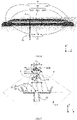


Classifications
-
- F—MECHANICAL ENGINEERING; LIGHTING; HEATING; WEAPONS; BLASTING
- F25—REFRIGERATION OR COOLING; COMBINED HEATING AND REFRIGERATION SYSTEMS; HEAT PUMP SYSTEMS; MANUFACTURE OR STORAGE OF ICE; LIQUEFACTION SOLIDIFICATION OF GASES
- F25D—REFRIGERATORS; COLD ROOMS; ICE-BOXES; COOLING OR FREEZING APPARATUS NOT OTHERWISE PROVIDED FOR
- F25D21/00—Defrosting; Preventing frosting; Removing condensed or defrost water
- F25D21/06—Removing frost
- F25D21/08—Removing frost by electric heating
-
- F—MECHANICAL ENGINEERING; LIGHTING; HEATING; WEAPONS; BLASTING
- F25—REFRIGERATION OR COOLING; COMBINED HEATING AND REFRIGERATION SYSTEMS; HEAT PUMP SYSTEMS; MANUFACTURE OR STORAGE OF ICE; LIQUEFACTION SOLIDIFICATION OF GASES
- F25D—REFRIGERATORS; COLD ROOMS; ICE-BOXES; COOLING OR FREEZING APPARATUS NOT OTHERWISE PROVIDED FOR
- F25D21/00—Defrosting; Preventing frosting; Removing condensed or defrost water
- F25D21/14—Collecting or removing condensed and defrost water; Drip trays
-
- H—ELECTRICITY
- H05—ELECTRIC TECHNIQUES NOT OTHERWISE PROVIDED FOR
- H05B—ELECTRIC HEATING; ELECTRIC LIGHT SOURCES NOT OTHERWISE PROVIDED FOR; CIRCUIT ARRANGEMENTS FOR ELECTRIC LIGHT SOURCES, IN GENERAL
- H05B3/00—Ohmic-resistance heating
- H05B3/40—Heating elements having the shape of rods or tubes
- H05B3/42—Heating elements having the shape of rods or tubes non-flexible
- H05B3/44—Heating elements having the shape of rods or tubes non-flexible heating conductor arranged within rods or tubes of insulating material
-
- F—MECHANICAL ENGINEERING; LIGHTING; HEATING; WEAPONS; BLASTING
- F25—REFRIGERATION OR COOLING; COMBINED HEATING AND REFRIGERATION SYSTEMS; HEAT PUMP SYSTEMS; MANUFACTURE OR STORAGE OF ICE; LIQUEFACTION SOLIDIFICATION OF GASES
- F25D—REFRIGERATORS; COLD ROOMS; ICE-BOXES; COOLING OR FREEZING APPARATUS NOT OTHERWISE PROVIDED FOR
- F25D2321/00—Details or arrangements for defrosting; Preventing frosting; Removing condensed or defrost water, not provided for in other groups of this subclass
- F25D2321/14—Collecting condense or defrost water; Removing condense or defrost water
- F25D2321/144—Collecting condense or defrost water; Removing condense or defrost water characterised by the construction of drip water collection pans
-
- F—MECHANICAL ENGINEERING; LIGHTING; HEATING; WEAPONS; BLASTING
- F25—REFRIGERATION OR COOLING; COMBINED HEATING AND REFRIGERATION SYSTEMS; HEAT PUMP SYSTEMS; MANUFACTURE OR STORAGE OF ICE; LIQUEFACTION SOLIDIFICATION OF GASES
- F25D—REFRIGERATORS; COLD ROOMS; ICE-BOXES; COOLING OR FREEZING APPARATUS NOT OTHERWISE PROVIDED FOR
- F25D2321/00—Details or arrangements for defrosting; Preventing frosting; Removing condensed or defrost water, not provided for in other groups of this subclass
- F25D2321/14—Collecting condense or defrost water; Removing condense or defrost water
- F25D2321/146—Collecting condense or defrost water; Removing condense or defrost water characterised by the pipes or pipe connections
-
- H—ELECTRICITY
- H05—ELECTRIC TECHNIQUES NOT OTHERWISE PROVIDED FOR
- H05B—ELECTRIC HEATING; ELECTRIC LIGHT SOURCES NOT OTHERWISE PROVIDED FOR; CIRCUIT ARRANGEMENTS FOR ELECTRIC LIGHT SOURCES, IN GENERAL
- H05B2203/00—Aspects relating to Ohmic resistive heating covered by group H05B3/00
- H05B2203/032—Heaters specially adapted for heating by radiation heating
Definitions
- the present invention relates to a defrosting device for defrosting an evaporator of a refrigerator and a refrigerator including the same.
- a defrosting device In order to defrost an evaporator, a defrosting device is widely used, and the defrosting device includes a glass tube heater below the evaporator.
- a temperature of an outer surface of the glass tube heater is required to be sufficiently lower than a flammable temperature of a solvent flowing in the evaporator.
- an insufficient defrosting performance may be obtained.
- frost in the evaporator above the glass tube heater is melted by heat transferred by natural convection due to the glass tube heater, water falling from the evaporator after the melting process may be refrozen in a tray disposed below the glass tube heater.
- Patent document 1 Publication No. JP2004198097 .
- the glass tube heater including the double-layer glass tube has a high manufacturing cost
- the defrosting device including the glass tube heater or the refrigerator including the defrosting device has an increased manufacturing cost
- An object of the present invention is to solve the above problems and to provide a defrosting device which may be manufactured at a low cost and has a sufficient defrosting function, and a refrigerator including the same.
- a defrosting device includes: a defrosting heater having a heating element in a single-layer glass tube with a circular cross section perpendicular to a length direction; a roof portion disposed above the glass tube and extending in the length direction of the glass tube, the roof portion being made of a metal sheet and having an upwards protruding shape; a tray disposed below the glass tube, extending in the length direction of the glass tube, and having an opening formed in a bottom thereof; and a drainage pipe extending downwards from the opening, wherein in a cross section perpendicular to the length direction of the glass tube, a top of the roof portion is located on a vertical line passing through a general center of the glass tube, and the roof portion is symmetrical with respect to the vertical line within at least a predetermined range on both sides of the vertical line, and in a cross section along the length direction of the glass tube including the vertical line, end regions on both sides of the roof portion in the length direction are inclined downwards to downwards reflect radiant heat from a
- the single-layer glass tube is used to reduce the manufacturing cost of the device. Even when input power of the defrosting heater is suppressed to reduce a temperature of an outer surface of the glass tube, the radiant heat from the defrosting heater may be reflected towards the tray 30 side by the roof portion, so as to melt frost in the tray.
- the upwards protruding shape of the roof portion is symmetrical with respect to the vertical line within at least the predetermined range on both sides of the vertical line passing through the general center of the glass tube, and further, in the cross section along the length direction of the glass tube including the above-mentioned vertical line, the upwards protruding shape of the roof portion is formed obliquely in the end regions on both sides, so as to downwards reflect the radiant heat from the lower side. That is, four corners of the roof portion are formed into a shape for improving reflection.
- the radiant heat with a small offset or deflection may be incident into a main part of the tray except a part directly below the glass tube.
- the opening of the tray is located directly below the glass tube, and therefore, the radiant heat from the defrosting device is directly incident to the opening and a periphery thereof.
- the frost refrozen in the tray may be melted and reliably discharged through the opening and the drainage pipe.
- a defrosting device which is manufactured at a low cost and has a sufficient defrosting performance may be provided.
- the present invention provides a defrosting device in which a lower end portion of the roof portion is disposed at a same position as or above an upper end of the glass tube in a height direction, and in the height direction, the top of the roof portion is disposed at a position higher than a position of the upper end of the glass tube by a length which is 1.5 times an outer diameter of the glass tube or less.
- the lower end portion of the roof portion is disposed at the same position as or above the upper end of the glass tube, frost adhering to an evaporator above the defrosting device may be reliably melted by the heat transferred by natural convection. Furthermore, since in the height direction, the top of the roof portion is disposed at the position higher than the position of the upper end of the glass tube by the length which is 1.5 times the outer diameter of the glass tube or less, the glass tube may be disposed near the evaporator, thus improving an effect of melting the frost adhering to the evaporator. Meanwhile, since the top of the roof portion is not too far away from the tray, the radiant heat from the defrosting heater may be strongly reflected towards the tray side by the roof portion, so as to improve the effect of melting the frost in the tray.
- the frost on the evaporator and the tray may be effectively melted to achieve a high defrosting performance.
- the present invention provides a defrosting device in which a width at a lower end of the roof portion is 2 to 3 times the outer diameter of the glass tube in the cross section perpendicular to the length direction of the glass tube.
- the width at the lower end of the roof portion is set to be 2 to 3 times the outer diameter of the glass tube, thus well balancing and effectively melting the frost of the evaporator and the tray.
- the present invention provides a defrosting device further including a defrosting component made of a bent metal rod, the defrosting component having: a hook portion formed at one end portion of the metal rod and inserted into a hole portion provided at the roof portion in a free rotation state; a heat receiving portion connected with the hook portion and extending obliquely downwards while connected with the roof portion; a bypassing portion connected with the heat receiving portion and bent to bypass the glass tube; and a heat dissipation portion connected with the bypassing portion and extending downwards into the tray and the drainage pipe.
- a defrosting component made of a bent metal rod, the defrosting component having: a hook portion formed at one end portion of the metal rod and inserted into a hole portion provided at the roof portion in a free rotation state; a heat receiving portion connected with the hook portion and extending obliquely downwards while connected with the roof portion; a bypassing portion connected with the heat receiving portion and bent to bypass the glass tube; and a heat dissipation portion connected
- the heat receiving portion comes into contact with the roof portion by gravity, and may receive the heat from the defrosting heater through a metal roof.
- the heat dissipation portion may be disposed inside the tray and the drainage pipe by gravity in a case where the bypassing portion does not interfere in the glass tube. The heat received by the roof portion is conducted through the bypassing portion to the heat dissipation portion extending downwards, and the heat may be supplied from the heat dissipation portion to the frost or water in the tray or the drainage pipe.
- manufacture may be realized at a low manufacturing cost, and the heat from the defrosting heater may be effectively supplied to the frost or water in the tray or the drainage pipe.
- a refrigerator according to the present invention is characterized by including the above-mentioned defrosting device.
- the refrigerator according to the present invention may also achieve any of the above-mentioned effects.
- a defrosting device which may be manufactured at a low cost and has a sufficient defrosting performance and a refrigerator including the same may be provided.
- 2-defrosting device 10-defrosting heater, 12-glass tube, 14-cover, 20-heater cover, 22-roof portion, 22A-first region, 22B-second region, 22C-third region, 22D-fourth region, 24-bracket, 26-hole portion, 30-tray, 30A-bottom, 30B-side wall, 32-opening, 40-drainage pipe, 50-defrosting component, 52-hook portion, 54-heat receiving portion, 56-bypassing portion, 58-heat dissipation portion, 100-refrigerator, 102A-freezing chamber, 102B-refrigerating chamber, 104A, 104B-inflow passage, 106-partition, 106A-blow-out port, 110-evaporator, 120-compressor, 130-fan, 140-damper, 150-drainage pipe, 160-evaporating pan, G-general center, VL-vertical line, and S-specified range.
- FIG. 1 is a side sectional view schematically showing an example of a refrigerator 100 including a defrosting device 2 according to an embodiment of the present invention.
- the refrigerator 100 shown in FIG. 1 includes a freezing chamber 102A and a refrigerating chamber 102B.
- Inflow passages 104A, 104B spaced apart by a partition 106 are provided on rear sides of the freezing chamber 102A and the refrigerating chamber 102B.
- An evaporator 110 is disposed in the inflow passage 104A on the freezing chamber 102A side, and a fan 130 is disposed above the evaporator 110.
- the defrosting device 2 according to each embodiment described below is disposed below the evaporator 110.
- a compressor 120 in communication with the evaporator 110 is disposed in a machinery chamber outside the rear side of the freezing chamber 102A.
- the following cycle is repeated: a refrigerant (gas) compressed by the compressor 120 is liquefied by a condenser, the liquefied refrigerant absorbs heat of the gas in a tank in the evaporator 110 and is vaporized, and the vaporized refrigerant is compressed again by the compressor 120.
- a damper 140 is disposed between the inflow passage 104A on the freezing chamber 102A side and the inflow passage 104B on the refrigerating chamber 102B side. In FIG. 1 , the damper 140 is shown in a closed state.
- the defrosting device 2 includes a defrosting heater 10, and when the compressor 120 and the fan 130 do not work, the defrosting heater 10 is turned on, thus heating and defrosting the heat exchange tube. Water falling after the frost on the evaporator 110 is melted is discharged from a drainage pipe 40 of the defrosting device 2, flows in a drainage pipe 150 of the refrigerator 100, and is discharged to a steam tray 160 disposed in the machinery chamber.
- FIG. 2 is a schematic perspective diagram schematically showing a defrosting device 2 according to a first embodiment of the present invention.
- FIG. 3 is a view showing a cross section perpendicular to the length direction of the glass tube 12 as viewed from the X-axis direction in FIG. 2 , and is a side sectional view schematically showing the defrosting device 2 according to the first embodiment of the present invention.
- FIG. 4 is a view showing a cross section along the length direction of the glass tube including a vertical line passing through a general center of a circular shape of the glass tube, and is a side sectional view schematically showing the defrosting device according to the first embodiment of the present invention. In FIG. 4 , a description of a tray is omitted.
- the defrosting device 2 according to the first embodiment of the present invention will be described with reference to FIGS. 2 to 4 .
- the defrosting device 2 includes a defrosting heater 10 having a heating element in a single-layer quartz glass tube 12. Furthermore, the defrosting device 2 includes a heater cover 20, and the heater cover 20 includes a roof portion 22 which is disposed above the glass tube 12, extends in the length direction of the glass tube 12, is made of a metal sheet and protrudes upwards. Furthermore, the defrosting device 2 includes a tray 30 disposed below the glass tube 12 and extending along the length direction of the glass tube 12, and a drainage pipe 40 extending downwards from an opening 32 provided in a bottom of the tray 30. FIG. 3 schematically shows the drainage pipe 40 shown in FIG. 2 .
- the defrosting device 2 includes a defrosting component 50 formed by bending a metal rod.
- the defrosting component 50 includes: a hook portion 52 formed at one end portion of the metal rod and inserted into a hole portion 26 provided in the metal sheet forming the roof portion 22 in a free rotation state, a heat receiving portion 54 connected with the hook portion 52 and extending obliquely downwards while connected with the metal sheet forming the roof portion 22, a bypassing portion 56 connected with the heat receiving portion 54 and bent to bypass the glass tube 12, and a heat dissipation portion 58 connected with the bypassing portion 56 and extending downwards into the tray 30 and the drainage pipe 40.
- the glass tube 12 included in the defrosting heater 10 in the present embodiment has an elongated cylindrical shape.
- the heating element made of a metal wire such as a nichrome wire, is disposed inside the glass tube 12.
- a coil-shaped heater made of a metal wire wound into a coil shape is disposed in a central heating region of the glass tube 12, and the metal wire extends outwards from both ends thereof.
- Both end portions of the glass tube 12 are covered with covers 14 made of a material having an excellent heat resistance and excellent electrical insulation, such as silicone rubber, or the like. Portions of the metal wire extending from both sides of the coil-shaped heater extend outside the glass tube 12 through the covers 14, and are electrically connected with external cables.
- input power is controlled, such that an outer surface of the heated glass tube 12 has a temperature of 360°C or lower.
- the evaporator 100 may be sufficiently defrosted practically even when such control is performed on the input power, which will be described in detail below.
- the heater cover 20 includes the roof portion 22 extending in the length direction of the glass tube 12, made of the metal sheet and protruding upwards, and brackets 24 provided on both sides of the roof portion 22 in the length direction.
- the covers 14 at both ends of the glass tube 12 are inserted into substantially C-shaped openings provided in the brackets 24, and the heater cover 20 is connected to the defrosting heater 10.
- an aluminum sheet having a high reflectance and a high thermal conductivity is used as the metal sheet forming the roof portion 22.
- the present invention is not limited thereto, and other arbitrary metal sheets, such as a copper sheet, may be used.
- the upwards protruding shape may also be formed by bending an aluminum sheet, or by joining 2 aluminum sheets.
- the metal sheet of the roof portion 22 is formed in the upwards protruding shape, and the upwards protruding shape is symmetrical with respect to the vertical line VL within at least a predetermined range S on both sides of the vertical line VL passing through the general center G of the circular shape of the glass tube 12.
- the predetermined range S on both sides of the vertical line VL refers to a range with a left side and a right side at a distance S from the vertical line VL in the Y-axis direction perpendicular to the vertical line VL in 2 regions divided by the vertical line VL in the Z-axis direction.
- the upwards protruding shape of the roof portion 22 has 2 flat plates: a first region 22A and a second region 22B. As described below, planes or smoothly curved surfaces may be used as reflection surfaces of the first region 22A and the second region 22B.
- the roof portion 22 in the cross section along the length direction of the glass tube 12, the roof portion 22 has a third region 22C and a fourth region 22D inclined downwards in end regions on both sides in the length direction, so as to downwards reflect radiant heat from a lower side. That is, as shown in FIG. 2 , the roof portion 22 has a structure like a hipped roof formed by 4 sheet-like members: the first to fourth regions 22A to 22D, and all side surfaces have shapes for improving reflection. Planes or smoothly curved surfaces may also be used as reflection surfaces of the third region 22C and the fourth region 22D.
- the radiant heat from the defrosting heater 10 may be reflected downwards and incident on a main part of the tray 30 below the defrosting heater, thus melting frost refrozen in the tray 30.
- the tray 30 extends along the length direction of the glass tube 12, has the bottom 30A and a side wall 30B surrounding the bottom 30A, and opens upwards.
- the opening 32 is provided in a substantially central position in a length direction of the bottom 30A of the tray 30.
- the bottom 30A of the tray 30 is inclined to minimize a height of the opening 32.
- the drainage pipe 40 is mounted to the opening 32 provided in the bottom 30A of the tray 30, and extends downwards from the opening 32.
- the opening 32 of the tray 30 is located directly below the glass tube 12.
- the opening 32 and a region around the opening may directly receive the radiant heat from the defrosting heater 10, so as to melt the frost refrozen in the tray 30.
- the tray 30 is preferably made of a metal material with a high thermal conductivity, such as aluminum.
- the drainage pipe 40 is preferably made of a resin materialwith an elasticity, or the like.
- FIG. 5 is a view showing the cross section perpendicular to the length direction of the glass tube as viewed from the X-axis direction in FIG. 2 , and is a side sectional view for illustrating an arrangement of a roof portion 22 according to an embodiment of the present invention.
- the dotted arrow indicates the radiant heat emitted from the defrosting heater 10
- the dash-and-dot arrow indicates an upward flow of ambient gas heated by the defrosting heater 10 due to natural convection.
- FIG. 5 illustrates the defrosting device according to the first embodiment shown in FIG. 3
- functions of the roof portion 22 are basically same in defrosting devices according to the second to fourth embodiments described with reference to FIGS. 6 to 8 .
- the upwards protruding shape of the roof portion 22 is symmetrical with respect to the vertical line VL within the predetermined range S on both sides of the vertical line VL passing through the general center G of the circular shape of the glass tube 12.
- the predetermined range S is uniform in an entire region of the roof portion 22, and the whole region is symmetrical with respect to the vertical line VL.
- the present invention is not limited thereto, and other cases will be described in detail below.
- the predetermined range S is preferably determined in accordance with a width of the tray 30 perpendicular to the length direction as viewed from the X-axis direction.
- the upwards protruding shape of the roof portion 22 is symmetrical with respect to the vertical line VL up to a range where reflected light reaches both end portions of the tray 30.
- the upwards protruding shape of the roof portion 22 is symmetrical with respect to the vertical line VL up to a range where the reflected light reaches at least the end portion close to the vertical line VL side.
- the radiant heat with a small offset or deviation may be incident into the main part of the tray 30, so as to efficiently melting the frost in the tray 30.
- the first region 22A and the second region 22B are shown as two side surfaces connected at a top P located on the vertical line VL. Moreover, an angle ⁇ formed by the first region 22A and the vertical line VL substantially coincides with an angle ⁇ formed by the second region 22B and the vertical line VL. Further, in an example shown in FIG. 5 , the first region 22A and the second region 22B also have uniform lengths.
- the first region 22A and the second region 22B form 2 equal sides of an isosceles triangle with a vertex P located on the vertical line VL as a vertex.
- the first region 22A and the second region 22B extend obliquely downwards to intersect with a horizontal line of a bottom surface of the tray 30, thus forming an upper half of a parallelogram.
- a center of the opening 32 of the tray 30 substantially coincides with the position of the vertical line VL. That is, the opening 32 of the tray 30 is located at a center of a parallelogram having the roof portion 22 of the upwards protruding shape and extended lines thereof as two sides.
- the radiant heat emitted upwards from the defrosting heater 10 may be reflected downwards by the roof portion 22, and the radiant heat with the small offset or deflection may be incident on the main part of the tray 30 except a part directly below the glass tube 12.
- the melting water flows into the drainage pipe 40 through a switch 32, flows in the drainage pipe 150 of the refrigerator 100, and is discharged to an evaporation pan 160 disposed in the machinery chamber.
- a position H1 of a lower end portion of the roof portion 22 is disposed above a position H0 of an upper end of the glass tube 12 in a height direction (the Z-axis direction).
- the present invention is not limited thereto, and the position H1 of the lower end portion of the roof portion 22 may be same as the position H0 of the upper end of the glass tube 12. That is, the position H1 of the lower end portion of the roof portion 22 is the same as or above the position H0 of the upper end of the glass tube 12 in the height direction (the Z-axis direction).
- the gas around the glass tube 12 heated by the defrosting heater 10 may efficiently flow upwards by natural convection.
- the heat may be provided for the evaporator 110 by natural convection heat transfer, thereby reliably melting the frost adhering to the evaporator 110.
- the top P of the roof portion 22 is disposed at a position H2 higher than the position H0 of the upper end of the glass tube 12 by a length which is 1.5 times an outer diameter of the glass tube 12 or less.
- the defrosting heater 10 may be relatively close to the evaporator 110, thus improving the effect of melting the frost adhering to the evaporator 110.
- the top P of the roof portion 22 is not too far away from the tray 30, the radiant heat from the defrosting heater 10 may be strongly reflected towards the tray 30 by the roof portion 22, so as to improve the effect of melting the frost in the tray 30.
- the frost on the evaporator 110 and the tray 30 may be effectively melted to achieve a high defrosting performance.
- a width W at a lower end of the roof portion 22 is 2 to 3 times the outer diameter D of the glass tube in the cross section perpendicular to the length direction of the glass tube 12 as viewed from the X-axis direction. Furthermore, when an end portion of the lower end of the roof portion 22 in the width direction has a distance M from the shape of the glass tube 12, 0.5D ⁇ M ⁇ D.
- the width W at the lower end of the roof portion 22 is set to be 2 to 3 times the outer diameter of the glass tube 12, thereby well balancing and effectively melting the frost of the evaporator 110 and the tray 30.
- a same relationship is also shown in a cross section perpendicular to the length direction of the glass tube 12 as viewed from a direction opposite to the X-axis direction.
- FIG. 6 is a view showing the cross section perpendicular to the length direction of the glass tube as viewed from the X-axis direction in FIG. 2 , and is a side sectional view schematically showing a defrosting device according to a second embodiment of the present invention.
- the roof portion 22 also has an upwards protruding shape formed by connecting a first region 22A and a second region 22B which have flat plate shapes.
- the second region 22B has a same length as the second region in the first embodiment, but the first region 22A is longer than the first region in the first embodiment.
- the upwards protruding shape of the roof portion 22 is symmetrical with respect to the vertical line VL within the predetermined range S on both sides of the vertical line passing through the general center G of the circular shape of the glass tube 12, but not symmetrical with respect to the vertical line VL in the whole region.
- a width is extended by an amount T.
- the end portions in the width direction of the tray 30 on the lower side have substantially the same distance from the vertical line VL in the Y-axis direction perpendicular to the vertical line VL, but the two end portions of the tray 30 in the width direction have different distances from the vertical line VL in the second embodiment.
- the upwards protruding shape of the roof portion 22 is symmetrical with respect to the vertical line VL in a range where the reflected light is incident on the end portion of the tray 30 in the width direction close to the vertical line VL side (the right end portion in the drawing).
- the reflected light is also incident on the other end portion (the left end portion in the drawing).
- a same relationship with the left and right reversed is shown in the cross section perpendicular to the length direction of the glass tube 12 as viewed from the direction opposite to the X-axis direction.
- FIG. 7 is a view showing the cross section perpendicular to the length direction of the glass tube 12 as viewed from the X-axis direction in FIG. 2 , and is a side sectional view schematically showing a defrosting device 2 according to a third embodiment of the present invention.
- the roof portion 22 is formed by the first region 22A and the second region 22B which have flat plate shapes, but in the third embodiment, the roof portion 22 is formed by a smooth curved surface.
- the radiant heat emitted upwards from the defrosting heater 10 may be reflected downwards by the roof portion 22, so as to be incident on the main part of the tray 30 except the region shielded by the glass tube 12.
- the whole region of the roof portion 22 is symmetrical with respect to the vertical line VL passing through the general center G of the circular shape of the glass tube 12.
- VL passing through the general center G of the circular shape of the glass tube 12.
- a same relationship is also shown in the cross section perpendicular to the length direction of the glass tube 12 as viewed from the direction opposite to the X-axis direction.
- FIG. 8 is a sectional view perpendicular to the length direction of the glass tube 12 as viewed from the X-axis direction in FIG. 2 , and is a side sectional view schematically showing a defrosting device 2 according to a fourth embodiment of the present invention.
- the roof portion 22 is also formed by a smooth curved surface.
- the upwards protruding shape of the roof portion 22 is symmetrical with respect to the vertical line VL within the predetermined range S on both sides of the vertical line passing through the general center G of the circular shape of the glass tube 12, but the roof portion 22 is not symmetrical with respect to the vertical line VL in the whole region.
- the width is extended by an amount T.
- the two end portions of the tray 30 in the width direction have different distances from the vertical line VL.
- the upwards protruding shape of the roof portion 22 is symmetrical with respect to the vertical line VL in the range where the reflected light is incident on the end portion of the tray 30 in the width direction close to the vertical line VL side (the right end portion in the drawing). Then, by adjusting the length of the roof portion 22, the reflected light is also incident on the other end portion (the left end portion in the drawing).
- a same relationship with the left and right reversed is shown in the cross section perpendicular to the length direction of the glass tube 12 as viewed from the direction opposite to the X-axis direction.
- the defrosting device 2 includes: the defrosting heater 10 having the heating element in the single-layer glass tube 12 with the circular cross section perpendicular to the length direction; the roof portion 22 disposed above the glass tube 12, extending in the length direction of the glass tube 12, made of the metal sheet and having the upwards protruding shape; the tray 30 disposed below the glass tube 12, extending in the length direction of the glass tube 12, and having the opening 32 formed in the bottom thereof; and the drainage pipe 40 extending downwards from the opening 32, wherein in the cross section perpendicular to the length direction of the glass tube 12, the top P of the roof portion 22 is located on the vertical line VL passing through the general center G of the glass tube 12, and the roof portion 22 is symmetrical with respect to the vertical line VL within at least the predetermined range on both sides of the vertical line VL, and in the cross section along the length direction of the glass tube 12 including the vertical line VL, the end regions on both sides of the roof
- the single-layer glass tube 12 is used to reduce a manufacturing cost of the device. Even when input power of the defrosting heater 10 is suppressed to reduce a temperature of an outer surface of the glass tube 12, the radiant heat from the defrosting heater 10 may be reflected towards the tray 30 side by the roof portion 22, so as to melt the frost in the tray 30.
- the upwards protruding shape of the roof portion 22 is symmetrical with respect to the vertical line VL in at least the predetermined range S on both sides of the vertical line VL passing through the general center G of the glass tube 12, and in the length direction (the X-axis direction shown in FIG. 2 ) of the glass tube 12, the end regions (see 22C and 22D in FIG.
- a defrosting device 2 which may be manufactured at a low cost and has a sufficient defrosting performance may be provided.
- the frost adhering to the evaporator 110 may be effectively melted by the heat transferred by natural convection.
- the top P of the roof portion 22 is disposed at the position H2 higher than the position H0 of the upper end of the glass tube 12 by the length which is 1.5 times the outer diameter of the glass tube 12 or less, thus improving the effect of melting the frost adhering to the evaporator 110 and the frost in the tray 30. With the arrangement of the above roof portion 22, the frost on the evaporator 110 and the tray 30 may be effectively melted to provide the high defrosting performance.
- the width W at the lower end of the roof portion 22 is 2 to 3 times the outer diameter D of the glass tube 12, thus well balancing and effectively melting the frost of the evaporator 110 and the tray 30.
- FIG. 9 is a perspective view for illustrating a defrosting component according to an embodiment of the present invention.
- FIG. 9 schematically shows the shape of the roof portion 22.
- Any of the defrosting devices 2 according to above-mentioned embodiments includes the defrosting component 50 formed by bending the metal rod.
- the defrosting component 50 has the hook portion 52 formed at one end portion of the metal rod and inserted into the hole portion 26 provided in the metal sheet forming the roof portion 22 in the free rotation state.
- the defrosting component 50 has the heat receiving portion 54 connected with the hook portion 52 and extending obliquely downwards while connected with the metal sheet forming the roof portion 22.
- the defrosting component 50 mounted, at one end portion thereof, to the roof portion 22 by the hook portion 52 in the free rotation state is suspended by gravity, and the heat receiving portion 54 extends obliquely downwards while coming into contact with the metal sheet forming the roof portion 22.
- the defrosting component 50 has the bypassing portion 56 connected with the heat receiving portion 54 and bent to bypass the glass tube 12. Since the heat receiving portion 54 and the metal sheet forming the roof portion 22 come into contact by gravity to have fixed positions, the bypassing portion 56 may be reliably separated from the glass tube 12. Further, the defrosting component 50 has the heat dissipation portion 58 connected with the bypassing portion 56 and extending downwards into the tray 30 and the drainage pipe 40. The defrosting component 50 terminates at an end portion of the heat dissipation portion 58.
- the heat receiving portion 54 comes into contact with the roof portion 22 by gravity, and therefore receives the heat from the defrosting heater 10 through the contact part of the metal roof portion 22. Furthermore, the heat received by the heat receiving portion 54 is conducted through the bypassing portion 56 to the heat dissipation portion 58 extending downwards. Thus, the heat is supplied from the heat dissipation portion 58 to the frost or water in the tray 30 or the drainage pipe 40. Therefore, the frost in the tray 30 or the drainage pipe 40 may be melted and discharged through the drainage pipe 40.
- the heat from the defrosting heater 10 may be effectively supplied to the frost or water in the tray 30 or the drainage pipe 40 at a low manufacturing cost.
- the defrosting component 50 may be rotated to be disposed along a surface of the roof portion 22. Therefore, when the defrosting device 2 is mounted in the refrigerator 100, or when components are dismounted or replaced, the defrosting component 50 is placed along the surface of the roof portion 22 and fixed using adhesive tape, or the like, thus preventing the defrosting component 50 from interfering with other members, so as to improve a working efficiency.
- the refrigerator 100 shown in FIG. 1 including the defrosting device 2 according to the above-mentioned embodiment may also achieve any of the above-mentioned effects.
Landscapes
- Engineering & Computer Science (AREA)
- Chemical & Material Sciences (AREA)
- Combustion & Propulsion (AREA)
- Physics & Mathematics (AREA)
- Mechanical Engineering (AREA)
- Thermal Sciences (AREA)
- General Engineering & Computer Science (AREA)
- Defrosting Systems (AREA)
- Removal Of Water From Condensation And Defrosting (AREA)
Abstract
Description
- The present invention relates to a defrosting device for defrosting an evaporator of a refrigerator and a refrigerator including the same.
- In order to defrost an evaporator, a defrosting device is widely used, and the defrosting device includes a glass tube heater below the evaporator. In such a refrigerator, a temperature of an outer surface of the glass tube heater is required to be sufficiently lower than a flammable temperature of a solvent flowing in the evaporator. However, when input power of the glass tube heater is reduced to lower the temperature of the outer surface of the glass tube heater, an insufficient defrosting performance may be obtained. In particular, even when frost in the evaporator above the glass tube heater is melted by heat transferred by natural convection due to the glass tube heater, water falling from the evaporator after the melting process may be refrozen in a tray disposed below the glass tube heater.
- In order to solve the problem, there is proposed a defrosting device with a defrosting heater in which a heating element is provided in a double-layer glass tube (for example, see patent document 1). In the defrosting device described in patent document 1, by using the double-layer glass tube, sufficient heat may be applied to melt the frost refrozen in the tray even when the outer surface of the glass tube heater has a low temperature.
- Patent document 1: Publication No.
JP2004198097 - However, the glass tube heater including the double-layer glass tube has a high manufacturing cost, and the defrosting device including the glass tube heater or the refrigerator including the defrosting device has an increased manufacturing cost.
- An object of the present invention is to solve the above problems and to provide a defrosting device which may be manufactured at a low cost and has a sufficient defrosting function, and a refrigerator including the same.
- A defrosting device according to the present invention includes: a defrosting heater having a heating element in a single-layer glass tube with a circular cross section perpendicular to a length direction; a roof portion disposed above the glass tube and extending in the length direction of the glass tube, the roof portion being made of a metal sheet and having an upwards protruding shape; a tray disposed below the glass tube, extending in the length direction of the glass tube, and having an opening formed in a bottom thereof; and a drainage pipe extending downwards from the opening, wherein in a cross section perpendicular to the length direction of the glass tube, a top of the roof portion is located on a vertical line passing through a general center of the glass tube, and the roof portion is symmetrical with respect to the vertical line within at least a predetermined range on both sides of the vertical line, and in a cross section along the length direction of the glass tube including the vertical line, end regions on both sides of the roof portion in the length direction are inclined downwards to downwards reflect radiant heat from a lower side, and the opening is located directly below the glass tube.
- According to the present invention, the single-layer glass tube is used to reduce the manufacturing cost of the device. Even when input power of the defrosting heater is suppressed to reduce a temperature of an outer surface of the glass tube, the radiant heat from the defrosting heater may be reflected towards the
tray 30 side by the roof portion, so as to melt frost in the tray. In particular, in the cross section perpendicular to the length direction of the glass tube, the upwards protruding shape of the roof portion is symmetrical with respect to the vertical line within at least the predetermined range on both sides of the vertical line passing through the general center of the glass tube, and further, in the cross section along the length direction of the glass tube including the above-mentioned vertical line, the upwards protruding shape of the roof portion is formed obliquely in the end regions on both sides, so as to downwards reflect the radiant heat from the lower side. That is, four corners of the roof portion are formed into a shape for improving reflection. Thus, the radiant heat with a small offset or deflection may be incident into a main part of the tray except a part directly below the glass tube. - Furthermore, the opening of the tray is located directly below the glass tube, and therefore, the radiant heat from the defrosting device is directly incident to the opening and a periphery thereof. Thus, the frost refrozen in the tray may be melted and reliably discharged through the opening and the drainage pipe.
- As mentioned above, a defrosting device which is manufactured at a low cost and has a sufficient defrosting performance may be provided.
- In addition, the present invention provides a defrosting device in which a lower end portion of the roof portion is disposed at a same position as or above an upper end of the glass tube in a height direction, and in the height direction, the top of the roof portion is disposed at a position higher than a position of the upper end of the glass tube by a length which is 1.5 times an outer diameter of the glass tube or less.
- According to the present invention, since the lower end portion of the roof portion is disposed at the same position as or above the upper end of the glass tube, frost adhering to an evaporator above the defrosting device may be reliably melted by the heat transferred by natural convection. Furthermore, since in the height direction, the top of the roof portion is disposed at the position higher than the position of the upper end of the glass tube by the length which is 1.5 times the outer diameter of the glass tube or less, the glass tube may be disposed near the evaporator, thus improving an effect of melting the frost adhering to the evaporator. Meanwhile, since the top of the roof portion is not too far away from the tray, the radiant heat from the defrosting heater may be strongly reflected towards the tray side by the roof portion, so as to improve the effect of melting the frost in the tray.
- With the arrangement of the roof portion as mentioned above, the frost on the evaporator and the tray may be effectively melted to achieve a high defrosting performance.
- In addition, the present invention provides a defrosting device in which a width at a lower end of the roof portion is 2 to 3 times the outer diameter of the glass tube in the cross section perpendicular to the length direction of the glass tube.
- The width at the lower end of the roof portion is set to be 2 to 3 times the outer diameter of the glass tube, thus well balancing and effectively melting the frost of the evaporator and the tray.
- Furthermore, the present invention provides a defrosting device further including a defrosting component made of a bent metal rod, the defrosting component having: a hook portion formed at one end portion of the metal rod and inserted into a hole portion provided at the roof portion in a free rotation state; a heat receiving portion connected with the hook portion and extending obliquely downwards while connected with the roof portion; a bypassing portion connected with the heat receiving portion and bent to bypass the glass tube; and a heat dissipation portion connected with the bypassing portion and extending downwards into the tray and the drainage pipe.
- According to the present invention, in the defrosting component mounted to the roof portion by the hook portion in the free rotation state, the heat receiving portion comes into contact with the roof portion by gravity, and may receive the heat from the defrosting heater through a metal roof. Furthermore, the heat dissipation portion may be disposed inside the tray and the drainage pipe by gravity in a case where the bypassing portion does not interfere in the glass tube. The heat received by the roof portion is conducted through the bypassing portion to the heat dissipation portion extending downwards, and the heat may be supplied from the heat dissipation portion to the frost or water in the tray or the drainage pipe.
- As mentioned above, by using the defrosting component, manufacture may be realized at a low manufacturing cost, and the heat from the defrosting heater may be effectively supplied to the frost or water in the tray or the drainage pipe.
- In addition, a refrigerator according to the present invention is characterized by including the above-mentioned defrosting device.
- The refrigerator according to the present invention may also achieve any of the above-mentioned effects.
- As mentioned above, in the present invention, a defrosting device which may be manufactured at a low cost and has a sufficient defrosting performance and a refrigerator including the same may be provided.
-
-
FIG. 1 schematically shows a side sectional view of a refrigerator having a defrosting device according to an embodiment of the present invention. -
FIG. 2 is a schematic perspective diagram schematically showing a defrosting device according to a first embodiment of the present invention. -
FIG. 3 is a view showing a cross section perpendicular to a length direction of a glass tube as viewed from the X-axis direction inFIG. 2 , and is a side sectional view schematically showing the defrosting device according to the first embodiment of the present invention. -
FIG. 4 is a view showing a cross section along the length direction of the glass tube, the view including a vertical line passing through a general center of a circular shape of the glass tube, and is a side sectional view schematically showing the defrosting device according to the first embodiment of the present invention. -
FIG. 5 is a view showing the cross section perpendicular to the length direction of the glass tube as viewed from the X-axis direction inFIG. 2 , and is a side sectional view for illustrating an arrangement of a roof portion according to an embodiment of the present invention. -
FIG. 6 is a view showing the cross section perpendicular to the length direction of the glass tube as viewed from the X-axis direction inFIG. 2 , and is a side sectional view schematically showing a defrosting device according to a second embodiment of the present invention. -
FIG. 7 is a view showing the cross section perpendicular to the length direction of the glass tube as viewed from the X-axis direction inFIG. 2 , and is a side sectional view schematically showing a defrosting device according to a third embodiment of the present invention. -
FIG. 8 is a view showing the cross section perpendicular to the length direction of the glass tube as viewed from the X-axis direction inFIG. 2 , and is a side sectional view schematically showing a defrosting device according to a fourth embodiment of the present invention. -
FIG. 9 is a perspective view for illustrating a defrosting component according to an embodiment of the present invention. - 2-defrosting device, 10-defrosting heater, 12-glass tube, 14-cover, 20-heater cover, 22-roof portion, 22A-first region, 22B-second region, 22C-third region, 22D-fourth region, 24-bracket, 26-hole portion, 30-tray, 30A-bottom, 30B-side wall, 32-opening, 40-drainage pipe, 50-defrosting component, 52-hook portion, 54-heat receiving portion, 56-bypassing portion, 58-heat dissipation portion, 100-refrigerator, 102A-freezing chamber, 102B-refrigerating chamber, 104A, 104B-inflow passage, 106-partition, 106A-blow-out port, 110-evaporator, 120-compressor, 130-fan, 140-damper, 150-drainage pipe, 160-evaporating pan, G-general center, VL-vertical line, and S-specified range.
- Embodiments for implementing the present invention will be described below with reference to accompanying drawings. A defrosting device described below is used for embodying the technical idea of the present invention, and the present invention is not limited to the following unless otherwise specified.
- In the drawings, members having the same function may be denoted by the same reference numerals. For convenience of explanation or understanding of key points, there are cases where the description is divided into embodiments for convenience, but parts of structures shown in different embodiments may be replaced or combined. In the embodiment described below, descriptions about matters common to the above are omitted, and only different points will be described. In particular, the same effects caused by the same structure will not be mentioned in turn in each embodiment. In order to clarify the description, the sizes, positional relationships, or the like, of members shown in each drawing may be shown in an expanded manner. In the following description and drawings, an X-axis, a Y-axis, and a Z-axis are shown assuming that a refrigerator is disposed on a floor. The Z-axis is used to indicate a vertical direction, and the X-axis is used to indicate a length direction of a
glass tube 12 included in a defrostingheater 10 described below. -
FIG. 1 is a side sectional view schematically showing an example of arefrigerator 100 including adefrosting device 2 according to an embodiment of the present invention. Therefrigerator 100 shown inFIG. 1 includes a freezingchamber 102A and a refrigeratingchamber 102B.Inflow passages partition 106 are provided on rear sides of the freezingchamber 102A and the refrigeratingchamber 102B. Anevaporator 110 is disposed in theinflow passage 104A on the freezingchamber 102A side, and afan 130 is disposed above theevaporator 110. Thedefrosting device 2 according to each embodiment described below is disposed below theevaporator 110. - A
compressor 120 in communication with theevaporator 110 is disposed in a machinery chamber outside the rear side of the freezingchamber 102A. The following cycle is repeated: a refrigerant (gas) compressed by thecompressor 120 is liquefied by a condenser, the liquefied refrigerant absorbs heat of the gas in a tank in theevaporator 110 and is vaporized, and the vaporized refrigerant is compressed again by thecompressor 120. Adamper 140 is disposed between theinflow passage 104A on the freezingchamber 102A side and theinflow passage 104B on the refrigeratingchamber 102B side. InFIG. 1 , thedamper 140 is shown in a closed state. - As shown by the dotted arrow in
FIG. 1 , when thecompressor 120 and thefan 130 are actuated in the state where the damper is closed, the gas in the freezingchamber 102A flows, and the cold gas passing through theevaporator 110 flows into the freezingchamber 102A from a blow-outport 106A provided in thepartition 106. The inflow gas circulates in the freezingchamber 102A and returns to a lower side of theevaporator 110 in theinflow passage 104A again. An interior of the freezingchamber 102A is cooled by the circulation of the gas cooled by theevaporator 110. In a state where thedamper 140 is opened, cool air also circulates on the refrigeratingchamber 102B side. - Moisture contained in the cooled air is condensed into frost and adheres to a surface of a heat exchange tube of the
evaporator 110. A cooling performance is degraded when a large amount of frost adheres to the heat exchange tube, and therefore, theevaporator 110 is required to be defrosted periodically. Therefore, thedefrosting device 2 is disposed below theevaporator 110. Thedefrosting device 2 includes adefrosting heater 10, and when thecompressor 120 and thefan 130 do not work, the defrostingheater 10 is turned on, thus heating and defrosting the heat exchange tube. Water falling after the frost on theevaporator 110 is melted is discharged from adrainage pipe 40 of thedefrosting device 2, flows in adrainage pipe 150 of therefrigerator 100, and is discharged to asteam tray 160 disposed in the machinery chamber. -
FIG. 2 is a schematic perspective diagram schematically showing adefrosting device 2 according to a first embodiment of the present invention.FIG. 3 is a view showing a cross section perpendicular to the length direction of theglass tube 12 as viewed from the X-axis direction inFIG. 2 , and is a side sectional view schematically showing thedefrosting device 2 according to the first embodiment of the present invention.FIG. 4 is a view showing a cross section along the length direction of the glass tube including a vertical line passing through a general center of a circular shape of the glass tube, and is a side sectional view schematically showing the defrosting device according to the first embodiment of the present invention. InFIG. 4 , a description of a tray is omitted. Next, thedefrosting device 2 according to the first embodiment of the present invention will be described with reference toFIGS. 2 to 4 . - The
defrosting device 2 according to the present embodiment includes adefrosting heater 10 having a heating element in a single-layerquartz glass tube 12. Furthermore, thedefrosting device 2 includes aheater cover 20, and theheater cover 20 includes aroof portion 22 which is disposed above theglass tube 12, extends in the length direction of theglass tube 12, is made of a metal sheet and protrudes upwards. Furthermore, thedefrosting device 2 includes atray 30 disposed below theglass tube 12 and extending along the length direction of theglass tube 12, and adrainage pipe 40 extending downwards from anopening 32 provided in a bottom of thetray 30.FIG. 3 schematically shows thedrainage pipe 40 shown inFIG. 2 . - Further, the
defrosting device 2 according to the present embodiment includes adefrosting component 50 formed by bending a metal rod. Thedefrosting component 50 includes: ahook portion 52 formed at one end portion of the metal rod and inserted into ahole portion 26 provided in the metal sheet forming theroof portion 22 in a free rotation state, aheat receiving portion 54 connected with thehook portion 52 and extending obliquely downwards while connected with the metal sheet forming theroof portion 22, a bypassingportion 56 connected with theheat receiving portion 54 and bent to bypass theglass tube 12, and aheat dissipation portion 58 connected with the bypassingportion 56 and extending downwards into thetray 30 and thedrainage pipe 40. - The
glass tube 12 included in thedefrosting heater 10 in the present embodiment has an elongated cylindrical shape. The heating element made of a metal wire, such as a nichrome wire, is disposed inside theglass tube 12. A coil-shaped heater made of a metal wire wound into a coil shape is disposed in a central heating region of theglass tube 12, and the metal wire extends outwards from both ends thereof. Both end portions of theglass tube 12 are covered withcovers 14 made of a material having an excellent heat resistance and excellent electrical insulation, such as silicone rubber, or the like. Portions of the metal wire extending from both sides of the coil-shaped heater extend outside theglass tube 12 through thecovers 14, and are electrically connected with external cables. - In order to comply with IEC regulations, input power is controlled, such that an outer surface of the
heated glass tube 12 has a temperature of 360°C or lower. Theevaporator 100 may be sufficiently defrosted practically even when such control is performed on the input power, which will be described in detail below. - The
heater cover 20 includes theroof portion 22 extending in the length direction of theglass tube 12, made of the metal sheet and protruding upwards, andbrackets 24 provided on both sides of theroof portion 22 in the length direction. Thecovers 14 at both ends of theglass tube 12 are inserted into substantially C-shaped openings provided in thebrackets 24, and theheater cover 20 is connected to thedefrosting heater 10. - In the present embodiment, an aluminum sheet having a high reflectance and a high thermal conductivity is used as the metal sheet forming the
roof portion 22. However, the present invention is not limited thereto, and other arbitrary metal sheets, such as a copper sheet, may be used. The upwards protruding shape may also be formed by bending an aluminum sheet, or by joining 2 aluminum sheets. - In the cross section perpendicular to the length direction of the
glass tube 12 as viewed from the X-axis direction, the metal sheet of theroof portion 22 is formed in the upwards protruding shape, and the upwards protruding shape is symmetrical with respect to the vertical line VL within at least a predetermined range S on both sides of the vertical line VL passing through the general center G of the circular shape of theglass tube 12. Here, the predetermined range S on both sides of the vertical line VL refers to a range with a left side and a right side at a distance S from the vertical line VL in the Y-axis direction perpendicular to the vertical line VL in 2 regions divided by the vertical line VL in the Z-axis direction. The upwards protruding shape of theroof portion 22 has 2 flat plates: afirst region 22A and asecond region 22B. As described below, planes or smoothly curved surfaces may be used as reflection surfaces of thefirst region 22A and thesecond region 22B. - Further, as shown in
FIG. 4 , in the cross section along the length direction of theglass tube 12, theroof portion 22 has a third region 22C and afourth region 22D inclined downwards in end regions on both sides in the length direction, so as to downwards reflect radiant heat from a lower side. That is, as shown inFIG. 2 , theroof portion 22 has a structure like a hipped roof formed by 4 sheet-like members: the first tofourth regions 22A to 22D, and all side surfaces have shapes for improving reflection. Planes or smoothly curved surfaces may also be used as reflection surfaces of the third region 22C and thefourth region 22D. - With the above structure, the radiant heat from the defrosting
heater 10 may be reflected downwards and incident on a main part of thetray 30 below the defrosting heater, thus melting frost refrozen in thetray 30. - The
tray 30 extends along the length direction of theglass tube 12, has the bottom 30A and aside wall 30B surrounding the bottom 30A, and opens upwards. Theopening 32 is provided in a substantially central position in a length direction of the bottom 30A of thetray 30. The bottom 30A of thetray 30 is inclined to minimize a height of theopening 32. Thus, the water falling from theevaporator 110 above the defrosting device flows in the bottom 30A of thetray 30 into theopening 32. Thedrainage pipe 40 is mounted to theopening 32 provided in the bottom 30A of thetray 30, and extends downwards from theopening 32. - In the cross section perpendicular to the length direction of the
glass tube 12 as viewed from the X-axis direction, theopening 32 of thetray 30 is located directly below theglass tube 12. With such an arrangement, theopening 32 and a region around the opening may directly receive the radiant heat from the defrostingheater 10, so as to melt the frost refrozen in thetray 30. - The
tray 30 is preferably made of a metal material with a high thermal conductivity, such as aluminum. In consideration of ease of mounting thedefrosting device 2 to therefrigerator 100, or the like, thedrainage pipe 40 is preferably made of a resin materialwith an elasticity, or the like. -
FIG. 5 is a view showing the cross section perpendicular to the length direction of the glass tube as viewed from the X-axis direction inFIG. 2 , and is a side sectional view for illustrating an arrangement of aroof portion 22 according to an embodiment of the present invention. InFIG. 5 andFIGS. 6 to 8 described below, the dotted arrow indicates the radiant heat emitted from the defrostingheater 10, and the dash-and-dot arrow indicates an upward flow of ambient gas heated by the defrostingheater 10 due to natural convection. AlthoughFIG. 5 illustrates the defrosting device according to the first embodiment shown inFIG. 3 , functions of theroof portion 22 are basically same in defrosting devices according to the second to fourth embodiments described with reference toFIGS. 6 to 8 . - In the cross section perpendicular to the length direction of the
glass tube 12 as viewed from the X-axis direction, the upwards protruding shape of theroof portion 22 is symmetrical with respect to the vertical line VL within the predetermined range S on both sides of the vertical line VL passing through the general center G of the circular shape of theglass tube 12. In the first embodiment, the predetermined range S is uniform in an entire region of theroof portion 22, and the whole region is symmetrical with respect to the vertical line VL. However, the present invention is not limited thereto, and other cases will be described in detail below. - The predetermined range S is preferably determined in accordance with a width of the
tray 30 perpendicular to the length direction as viewed from the X-axis direction. In a case where both end portions of thetray 30 in the width direction are located at a same distance from the vertical line VL, preferably, the upwards protruding shape of theroof portion 22 is symmetrical with respect to the vertical line VL up to a range where reflected light reaches both end portions of thetray 30. In a case where both end portions of thetray 30 in the width direction are located at different distances from the vertical line VL, preferably, the upwards protruding shape of theroof portion 22 is symmetrical with respect to the vertical line VL up to a range where the reflected light reaches at least the end portion close to the vertical line VL side. Thus, the radiant heat with a small offset or deviation may be incident into the main part of thetray 30, so as to efficiently melting the frost in thetray 30. - In the cross section perpendicular to the length direction of the
glass tube 12 as viewed from the X-axis direction, thefirst region 22A and thesecond region 22B are shown as two side surfaces connected at a top P located on the vertical line VL. Moreover, an angle θ formed by thefirst region 22A and the vertical line VL substantially coincides with an angle θ formed by thesecond region 22B and the vertical line VL. Further, in an example shown inFIG. 5 , thefirst region 22A and thesecond region 22B also have uniform lengths. - This case may also be considered as follows: in the cross section perpendicular to the length direction of the
glass tube 12 as viewed from the X-axis direction, thefirst region 22A and thesecond 2 equal sides of an isosceles triangle with a vertex P located on the vertical line VL as a vertex.region 22B form - As shown by the double-dot dash line in
FIG. 5 , thefirst region 22A and thesecond region 22B extend obliquely downwards to intersect with a horizontal line of a bottom surface of thetray 30, thus forming an upper half of a parallelogram. Moreover, a center of theopening 32 of thetray 30 substantially coincides with the position of the vertical line VL. That is, theopening 32 of thetray 30 is located at a center of a parallelogram having theroof portion 22 of the upwards protruding shape and extended lines thereof as two sides. - With such an arrangement, the radiant heat emitted upwards from the defrosting
heater 10 may be reflected downwards by theroof portion 22, and the radiant heat with the small offset or deflection may be incident on the main part of thetray 30 except a part directly below theglass tube 12. A region where the reflected light from theroof portion 22 does not reach exists directly below theglass tube 12, but the radiant heat emitted downwards from the defrostingheater 10 is directly incident on such a region, thus efficiently melting the frost refrozen in the main part of thetray 30. The melting water flows into thedrainage pipe 40 through aswitch 32, flows in thedrainage pipe 150 of therefrigerator 100, and is discharged to anevaporation pan 160 disposed in the machinery chamber. - In the example shown in
FIG. 5 , a position H1 of a lower end portion of theroof portion 22 is disposed above a position H0 of an upper end of theglass tube 12 in a height direction (the Z-axis direction). However, the present invention is not limited thereto, and the position H1 of the lower end portion of theroof portion 22 may be same as the position H0 of the upper end of theglass tube 12. That is, the position H1 of the lower end portion of theroof portion 22 is the same as or above the position H0 of the upper end of theglass tube 12 in the height direction (the Z-axis direction). - With such a setting, the gas around the
glass tube 12 heated by the defrostingheater 10 may efficiently flow upwards by natural convection. Thus, the heat may be provided for theevaporator 110 by natural convection heat transfer, thereby reliably melting the frost adhering to theevaporator 110. - Furthermore, in the height direction (the Z-axis direction), the top P of the
roof portion 22 is disposed at a position H2 higher than the position H0 of the upper end of theglass tube 12 by a length which is 1.5 times an outer diameter of theglass tube 12 or less. With such a setting, the defrostingheater 10 may be relatively close to theevaporator 110, thus improving the effect of melting the frost adhering to theevaporator 110. Meanwhile, since the top P of theroof portion 22 is not too far away from thetray 30, the radiant heat from the defrostingheater 10 may be strongly reflected towards thetray 30 by theroof portion 22, so as to improve the effect of melting the frost in thetray 30. With the arrangement of theroof portion 22 as mentioned above, the frost on theevaporator 110 and thetray 30 may be effectively melted to achieve a high defrosting performance. - Furthermore, in the present embodiment, a width W at a lower end of the
roof portion 22 is 2 to 3 times the outer diameter D of the glass tube in the cross section perpendicular to the length direction of theglass tube 12 as viewed from the X-axis direction. Furthermore, when an end portion of the lower end of theroof portion 22 in the width direction has a distance M from the shape of theglass tube 12, 0.5D≤M≤D. - When the width W at the lower end of the
roof portion 22 is not much greater than the outer diameter of theglass tube 12, the heat generated by the defrostingheater 10 is unable to be sufficiently reflected downwards. On the other hand, when the width W at the lower end of theroof portion 22 is considerably greater than the outer diameter of theglass tube 12, the heat is difficult to be supplied to theevaporator 110 side above the defrosting device by natural convection. Therefore, the width W at the lower end of theroof portion 22 is set to be 2 to 3 times the outer diameter of theglass tube 12, thereby well balancing and effectively melting the frost of theevaporator 110 and thetray 30. A same relationship is also shown in a cross section perpendicular to the length direction of theglass tube 12 as viewed from a direction opposite to the X-axis direction. -
FIG. 6 is a view showing the cross section perpendicular to the length direction of the glass tube as viewed from the X-axis direction inFIG. 2 , and is a side sectional view schematically showing a defrosting device according to a second embodiment of the present invention. In thedefrosting device 2 according to the second embodiment, theroof portion 22 also has an upwards protruding shape formed by connecting afirst region 22A and asecond region 22B which have flat plate shapes. However, in the cross section perpendicular to the length direction of theglass tube 12 as viewed from the X-axis direction, thesecond region 22B has a same length as the second region in the first embodiment, but thefirst region 22A is longer than the first region in the first embodiment. - As shown in
FIG. 6 , in the cross section perpendicular to the length direction of theglass tube 12 as viewed from the X-axis direction, the upwards protruding shape of theroof portion 22 is symmetrical with respect to the vertical line VL within the predetermined range S on both sides of the vertical line passing through the general center G of the circular shape of theglass tube 12, but not symmetrical with respect to the vertical line VL in the whole region. In onefirst region 22A of theroof portion 22, a width is extended by an amount T. - In the above-mentioned first embodiment, in the cross section perpendicular to the length direction of the
glass tube 12 as viewed from the X-axis direction, the end portions in the width direction of thetray 30 on the lower side have substantially the same distance from the vertical line VL in the Y-axis direction perpendicular to the vertical line VL, but the two end portions of thetray 30 in the width direction have different distances from the vertical line VL in the second embodiment. The upwards protruding shape of theroof portion 22 is symmetrical with respect to the vertical line VL in a range where the reflected light is incident on the end portion of thetray 30 in the width direction close to the vertical line VL side (the right end portion in the drawing). Then, by adjusting a length of theroof portion 22, the reflected light is also incident on the other end portion (the left end portion in the drawing). A same relationship with the left and right reversed is shown in the cross section perpendicular to the length direction of theglass tube 12 as viewed from the direction opposite to the X-axis direction. -
FIG. 7 is a view showing the cross section perpendicular to the length direction of theglass tube 12 as viewed from the X-axis direction inFIG. 2 , and is a side sectional view schematically showing adefrosting device 2 according to a third embodiment of the present invention. - In the defrosting devices according to the first and second embodiments described above, the
roof portion 22 is formed by thefirst region 22A and thesecond region 22B which have flat plate shapes, but in the third embodiment, theroof portion 22 is formed by a smooth curved surface. - In this case, by appropriately determining curvature of the curved surface of the
roof portion 22, as shown inFIG. 7 , the radiant heat emitted upwards from the defrostingheater 10 may be reflected downwards by theroof portion 22, so as to be incident on the main part of thetray 30 except the region shielded by theglass tube 12. In the third embodiment, similarly to the first embodiment, the whole region of theroof portion 22 is symmetrical with respect to the vertical line VL passing through the general center G of the circular shape of theglass tube 12. A same relationship is also shown in the cross section perpendicular to the length direction of theglass tube 12 as viewed from the direction opposite to the X-axis direction. -
FIG. 8 is a sectional view perpendicular to the length direction of theglass tube 12 as viewed from the X-axis direction inFIG. 2 , and is a side sectional view schematically showing adefrosting device 2 according to a fourth embodiment of the present invention. - In the fourth embodiment, the
roof portion 22 is also formed by a smooth curved surface. In the cross section perpendicular to the length direction of theglass tube 12 as viewed from the X-axis direction, the upwards protruding shape of theroof portion 22 is symmetrical with respect to the vertical line VL within the predetermined range S on both sides of the vertical line passing through the general center G of the circular shape of theglass tube 12, but theroof portion 22 is not symmetrical with respect to the vertical line VL in the whole region. In onefirst region 22A of theroof portion 22, the width is extended by an amount T. - In the fourth embodiment, in the cross section perpendicular to the length direction of the
glass tube 12 as viewed from the X-axis direction ofFIG. 2 , the two end portions of thetray 30 in the width direction have different distances from the vertical line VL. The upwards protruding shape of theroof portion 22 is symmetrical with respect to the vertical line VL in the range where the reflected light is incident on the end portion of thetray 30 in the width direction close to the vertical line VL side (the right end portion in the drawing). Then, by adjusting the length of theroof portion 22, the reflected light is also incident on the other end portion (the left end portion in the drawing). A same relationship with the left and right reversed is shown in the cross section perpendicular to the length direction of theglass tube 12 as viewed from the direction opposite to the X-axis direction. - As mentioned above, the defrosting device 2 according to any one of the first to fourth embodiments of the present invention described above includes: the defrosting heater 10 having the heating element in the single-layer glass tube 12 with the circular cross section perpendicular to the length direction; the roof portion 22 disposed above the glass tube 12, extending in the length direction of the glass tube 12, made of the metal sheet and having the upwards protruding shape; the tray 30 disposed below the glass tube 12, extending in the length direction of the glass tube 12, and having the opening 32 formed in the bottom thereof; and the drainage pipe 40 extending downwards from the opening 32, wherein in the cross section perpendicular to the length direction of the glass tube 12, the top P of the roof portion 22 is located on the vertical line VL passing through the general center G of the glass tube 12, and the roof portion 22 is symmetrical with respect to the vertical line VL within at least the predetermined range on both sides of the vertical line VL, and in the cross section along the length direction of the glass tube 12 including the vertical line VL, the end regions on both sides of the roof portion 22 in the length direction are inclined downwards to downwards reflect the radiant heat from the lower side, and the opening 32 is located directly below the glass tube 12.
- The single-
layer glass tube 12 is used to reduce a manufacturing cost of the device. Even when input power of the defrostingheater 10 is suppressed to reduce a temperature of an outer surface of theglass tube 12, the radiant heat from the defrostingheater 10 may be reflected towards thetray 30 side by theroof portion 22, so as to melt the frost in thetray 30. In particular, the upwards protruding shape of theroof portion 22 is symmetrical with respect to the vertical line VL in at least the predetermined range S on both sides of the vertical line VL passing through the general center G of theglass tube 12, and in the length direction (the X-axis direction shown inFIG. 2 ) of theglass tube 12, the end regions (see 22C and 22D inFIG. 4 ) on both sides are inclined to downwards reflect the radiant heat from the lower side, and theopening 32 of thetray 30 is located directly below theglass tube 12, thus using the reflected heat from theroof portion 22 and the radiant heat directly received from the defrostingheater 10, and making the radiant heat with the small offset or deflection incident into the main part of thetray 30. Therefore, the frost adhering to theevaporator 110 may be melted and discharged through theopening 32 of thetray 30 and thedrainage pipe 40. As mentioned above, adefrosting device 2 which may be manufactured at a low cost and has a sufficient defrosting performance may be provided. - In addition, in the
defrosting devices 2 according to the first to fourth embodiments, since the position H1 of the lower end portion of theroof portion 22 is the same as or above the position H0 of the upper end of theglass tube 22 in the height direction (the Z-axis direction), the frost adhering to theevaporator 110 may be effectively melted by the heat transferred by natural convection. Further, in the height direction (the Z-axis direction), the top P of theroof portion 22 is disposed at the position H2 higher than the position H0 of the upper end of theglass tube 12 by the length which is 1.5 times the outer diameter of theglass tube 12 or less, thus improving the effect of melting the frost adhering to theevaporator 110 and the frost in thetray 30. With the arrangement of theabove roof portion 22, the frost on theevaporator 110 and thetray 30 may be effectively melted to provide the high defrosting performance. - In addition, in the
defrosting devices 2 according to the first to fourth embodiments, the width W at the lower end of theroof portion 22 is 2 to 3 times the outer diameter D of theglass tube 12, thus well balancing and effectively melting the frost of theevaporator 110 and thetray 30. -
FIG. 9 is a perspective view for illustrating a defrosting component according to an embodiment of the present invention.FIG. 9 schematically shows the shape of theroof portion 22. Any of thedefrosting devices 2 according to above-mentioned embodiments includes thedefrosting component 50 formed by bending the metal rod. As shown inFIG. 3 or9 , thedefrosting component 50 has thehook portion 52 formed at one end portion of the metal rod and inserted into thehole portion 26 provided in the metal sheet forming theroof portion 22 in the free rotation state. Further, thedefrosting component 50 has theheat receiving portion 54 connected with thehook portion 52 and extending obliquely downwards while connected with the metal sheet forming theroof portion 22. Thedefrosting component 50 mounted, at one end portion thereof, to theroof portion 22 by thehook portion 52 in the free rotation state is suspended by gravity, and theheat receiving portion 54 extends obliquely downwards while coming into contact with the metal sheet forming theroof portion 22. - Further, the
defrosting component 50 has the bypassingportion 56 connected with theheat receiving portion 54 and bent to bypass theglass tube 12. Since theheat receiving portion 54 and the metal sheet forming theroof portion 22 come into contact by gravity to have fixed positions, the bypassingportion 56 may be reliably separated from theglass tube 12. Further, thedefrosting component 50 has theheat dissipation portion 58 connected with the bypassingportion 56 and extending downwards into thetray 30 and thedrainage pipe 40. Thedefrosting component 50 terminates at an end portion of theheat dissipation portion 58. - In the
defrosting component 50 mounted to theroof portion 22 by thehook portion 52 in the free rotation state, theheat receiving portion 54 comes into contact with theroof portion 22 by gravity, and therefore receives the heat from the defrostingheater 10 through the contact part of themetal roof portion 22. Furthermore, the heat received by theheat receiving portion 54 is conducted through the bypassingportion 56 to theheat dissipation portion 58 extending downwards. Thus, the heat is supplied from theheat dissipation portion 58 to the frost or water in thetray 30 or thedrainage pipe 40. Therefore, the frost in thetray 30 or thedrainage pipe 40 may be melted and discharged through thedrainage pipe 40. - As mentioned above, by using the
defrosting component 50 in addition to theroof portion 22, the heat from the defrostingheater 10 may be effectively supplied to the frost or water in thetray 30 or thedrainage pipe 40 at a low manufacturing cost. - Further, as shown by arrows A, B in
FIG. 9 , thedefrosting component 50 may be rotated to be disposed along a surface of theroof portion 22. Therefore, when thedefrosting device 2 is mounted in therefrigerator 100, or when components are dismounted or replaced, thedefrosting component 50 is placed along the surface of theroof portion 22 and fixed using adhesive tape, or the like, thus preventing thedefrosting component 50 from interfering with other members, so as to improve a working efficiency. - The
refrigerator 100 shown inFIG. 1 including thedefrosting device 2 according to the above-mentioned embodiment may also achieve any of the above-mentioned effects. - While the embodiments of the present invention have been described, the disclosure may vary in details of the structure, and combinations of elements, changes of sequences, or the like, of the embodiments may be realized without departing from the scope and idea claimed by the present invention.
Claims (10)
- A defrosting device (2), comprising:a defrosting heater (10) having a heating element in a single-layer glass tube (12) with a circular cross section perpendicular to a length direction;a roof portion (22) disposed above the glass tube (12) and extending in the length direction of the glass tube (12), the roof portion (22) being made of a metal sheet and having an upwards protruding shape;a tray (30) disposed below the glass tube (12), extending in the length direction of the glass tube (12), and having an opening (32) formed in a bottom (30A) thereof; anda drainage pipe (40) extending downwards from the opening (32),wherein in a cross section perpendicular to the length direction of the glass tube (12),a top of the roof portion (22) is located on a vertical line (VL) passing through a general center (G) of the glass tube (12), and the roof portion (22) is symmetrical with respect to the vertical line (VL) within at least a predetermined range (2) on both sides of the vertical line (VL), andin a cross section along the length direction of the glass tube (12) comprising the vertical line (VL), end regions on both sides of the roof portion (22) in the length direction are inclined downwards to downwards reflect radiant heat from a lower side, and the opening (32) is located directly below the glass tube (12).
- The defrosting device (2) according to claim 1, wherein a lower end portion of the roof portion (22) is disposed at a same position as or above an upper end of the glass tube (12) in a height direction, and
in the height direction, the top of the roof portion (22) is disposed at a position higher than a position of the upper end of the glass tube (12) by a length which is 1.5 times an outer diameter of the glass tube (12) or less. - The defrosting device (2) according to claim 1, wherein a width at a lower end of the roof portion (22) is 2 to 3 times the outer diameter of the glass tube (12) in the cross section perpendicular to the length direction of the glass tube (12).
- The defrosting device (2) according to claim 1, further comprising a defrosting component (50) made of a bent metal rod,
the defrosting component (50) having:a hook portion (52) formed at one end portion of the metal rod and inserted into a hole portion (26) provided at the roof portion (22) in a free rotation state;a heat receiving portion (54) connected with the hook portion (52) and extending obliquely downwards while connected with the roof portion (22);a bypassing portion (56) connected with the heat receiving portion (54) and bent to bypass the glass tube (12); anda heat dissipation portion (58) connected with the bypassing portion (56) and extending downwards into the tray (30) and the drainage pipe (40). - The defrosting device (2) according to claim 1, wherein the roof portion (22) is formed by a first region (22A) and a second region (22B) having flat plate shapes; or the roof portion (22) is formed by a first region (22A) and a second region (22B) having curved surface shapes.
- The defrosting device (2) according to claim 5, wherein the first region (22A) and the second region (22B) are symmetrically arranged with respect to the vertical line (VL).
- The defrosting device (2) according to claim 5, wherein an angle θ formed by the first region (22A) and the vertical line (VL) coincides with an angle θ formed by the second region (22B) and the vertical line (VL), and the first region (22A) is longer than the second region (22B).
- The defrosting device (2) according to claim 1, wherein the roof portion (22) has a third region (22C) and a fourth region (22D) inclined downwards in end regions on both sides in the length direction thereof.
- The defrosting device (2) according to claim 8, wherein planes or curved surfaces serve as reflection surfaces of the third region (22C) and the fourth region (22D).
- A refrigerator comprising the defrosting device (2) according to claim 1.
Applications Claiming Priority (2)
| Application Number | Priority Date | Filing Date | Title |
|---|---|---|---|
| JP2019204064A JP7374464B2 (en) | 2019-11-11 | 2019-11-11 | Refrigerator with defrost device and defrost device |
| PCT/CN2020/127645 WO2021093713A1 (en) | 2019-11-11 | 2020-11-10 | Defrosting device and refrigerator comprising same |
Publications (2)
| Publication Number | Publication Date |
|---|---|
| EP4060261A1 true EP4060261A1 (en) | 2022-09-21 |
| EP4060261A4 EP4060261A4 (en) | 2022-12-07 |
Family
ID=75897188
Family Applications (1)
| Application Number | Title | Priority Date | Filing Date |
|---|---|---|---|
| EP20887092.3A Pending EP4060261A4 (en) | 2019-11-11 | 2020-11-10 | DEFROST DEVICE AND REFRIGERATOR COMPRISING THE SAME |
Country Status (4)
| Country | Link |
|---|---|
| EP (1) | EP4060261A4 (en) |
| JP (2) | JP7374464B2 (en) |
| CN (1) | CN114761747A (en) |
| WO (1) | WO2021093713A1 (en) |
Families Citing this family (2)
| Publication number | Priority date | Publication date | Assignee | Title |
|---|---|---|---|---|
| CN115406169B (en) * | 2022-08-22 | 2023-10-20 | 藤泽电工(上海)有限公司 | Durable waterproof defrosting device |
| CN119164237B (en) * | 2024-11-20 | 2025-01-28 | 锦益深冷(常州)能源科技有限公司 | Air-temperature gasifier with defrosting structure |
Family Cites Families (21)
| Publication number | Priority date | Publication date | Assignee | Title |
|---|---|---|---|---|
| JPH08313146A (en) * | 1995-05-16 | 1996-11-29 | Sanyo Electric Co Ltd | Defrosted water draining device for refrigerator with deep freezer |
| JPH10311660A (en) * | 1997-05-09 | 1998-11-24 | Matsushita Refrig Co Ltd | Refrigerator |
| JP3599977B2 (en) * | 1997-10-31 | 2004-12-08 | 三洋電機株式会社 | Refrigerator drainage device |
| KR100288262B1 (en) * | 1998-06-30 | 2001-05-02 | 전주범 | Defrost heater protection device of refrigerator |
| JP2000314581A (en) * | 1999-04-28 | 2000-11-14 | Sanyo Electric Co Ltd | Drain device of refrigerator |
| JP2004183998A (en) * | 2002-12-04 | 2004-07-02 | Toshiba Corp | refrigerator |
| JP3580307B2 (en) * | 2003-02-20 | 2004-10-20 | 松下電器産業株式会社 | Defrost heater |
| JP3554562B2 (en) | 2003-06-02 | 2004-08-18 | 松下冷機株式会社 | Defrost heater and refrigerator equipped with defrost heater |
| JP2005055004A (en) * | 2003-08-04 | 2005-03-03 | Hitachi Home & Life Solutions Inc | Refrigerator |
| JP2006010151A (en) * | 2004-06-24 | 2006-01-12 | Hitachi Home & Life Solutions Inc | refrigerator |
| JP4500645B2 (en) * | 2004-10-12 | 2010-07-14 | 日立アプライアンス株式会社 | refrigerator |
| CN100513950C (en) * | 2005-05-12 | 2009-07-15 | 松下电器产业株式会社 | Cooler with defrosting device and refrigerator having cooler with defrosting device |
| KR20090036837A (en) * | 2007-10-10 | 2009-04-15 | 주식회사 대우일렉트로닉스 | Evaporator with defrost heater |
| KR20090066690A (en) * | 2007-12-20 | 2009-06-24 | 주식회사 대우일렉트로닉스 | Defroster for refrigerator |
| JP2013245885A (en) * | 2012-05-28 | 2013-12-09 | Panasonic Corp | Refrigerator |
| CN203605587U (en) * | 2013-11-05 | 2014-05-21 | 合肥美的电冰箱有限公司 | Refrigerator |
| CN204006894U (en) * | 2014-05-30 | 2014-12-10 | 松下电器研究开发(苏州)有限公司 | Refrigerator |
| CN204648801U (en) * | 2014-12-11 | 2015-09-16 | 苏州三星电子有限公司 | A kind of drainpipe and there is the refrigerator of this drainpipe |
| CN207741416U (en) * | 2017-10-31 | 2018-08-17 | 合肥华凌股份有限公司 | A kind of the heat conduction probe assembly and its refrigerator defrost component of heating tube |
| CN108120211A (en) * | 2017-11-29 | 2018-06-05 | 青岛海尔股份有限公司 | A kind of automatic refrigerator defrosting system and with its refrigerator |
| CN210220362U (en) * | 2019-05-31 | 2020-03-31 | 松下电器研究开发(苏州)有限公司 | Refrigerator with a door |
-
2019
- 2019-11-11 JP JP2019204064A patent/JP7374464B2/en active Active
-
2020
- 2020-11-10 CN CN202080077687.2A patent/CN114761747A/en active Pending
- 2020-11-10 EP EP20887092.3A patent/EP4060261A4/en active Pending
- 2020-11-10 WO PCT/CN2020/127645 patent/WO2021093713A1/en not_active Ceased
-
2023
- 2023-10-18 JP JP2023179236A patent/JP7486864B2/en active Active
Also Published As
| Publication number | Publication date |
|---|---|
| JP7374464B2 (en) | 2023-11-07 |
| WO2021093713A1 (en) | 2021-05-20 |
| JP7486864B2 (en) | 2024-05-20 |
| JP2024001226A (en) | 2024-01-09 |
| EP4060261A4 (en) | 2022-12-07 |
| CN114761747A (en) | 2022-07-15 |
| JP2021076307A (en) | 2021-05-20 |
Similar Documents
| Publication | Publication Date | Title |
|---|---|---|
| EP2821718B1 (en) | Outdoor unit for refrigeration device | |
| US5097897A (en) | Heat exchanging device | |
| JP7486864B2 (en) | Defrosting device and refrigerator equipped with defrosting device | |
| CN100439831C (en) | refrigerator | |
| JP2003194452A (en) | Device for defrosting evaporator for refrigerator | |
| WO2021258819A1 (en) | Refrigerator | |
| US20240328704A1 (en) | Refrigerator | |
| WO2020166308A1 (en) | Defrosting device and refrigerator equipped with same | |
| JP7096413B2 (en) | Outdoor unit of refrigeration cycle equipment | |
| EP2370759B1 (en) | A cooling device comprising an evaporator | |
| JP3404395B2 (en) | refrigerator | |
| CN210772965U (en) | A freezing and refrigerating device | |
| KR101951207B1 (en) | Defrosting heater for pcm(phase change material) cold storage module | |
| CN220017870U (en) | Evaporation device, refrigerator and freezer | |
| CN221924162U (en) | refrigerator | |
| CN222703590U (en) | Refrigerating apparatus | |
| CN110285604A (en) | Evaporator assembly and refrigeration equipment therewith | |
| CN112204326B (en) | Defrosting device | |
| JPH09292188A (en) | Heat exchanger | |
| JP6976565B2 (en) | refrigerator | |
| WO2011080089A2 (en) | A cooling device | |
| KR19990036171U (en) | Defrost Heater in Refrigerator | |
| CN120970152A (en) | Refrigerating apparatus | |
| CN109341146A (en) | A kind of Thermal Performance of Micro Channels device assembly and refrigerator | |
| JP2015031438A (en) | Refrigerator |
Legal Events
| Date | Code | Title | Description |
|---|---|---|---|
| STAA | Information on the status of an ep patent application or granted ep patent |
Free format text: STATUS: THE INTERNATIONAL PUBLICATION HAS BEEN MADE |
|
| PUAI | Public reference made under article 153(3) epc to a published international application that has entered the european phase |
Free format text: ORIGINAL CODE: 0009012 |
|
| STAA | Information on the status of an ep patent application or granted ep patent |
Free format text: STATUS: REQUEST FOR EXAMINATION WAS MADE |
|
| 17P | Request for examination filed |
Effective date: 20220331 |
|
| AK | Designated contracting states |
Kind code of ref document: A1 Designated state(s): AL AT BE BG CH CY CZ DE DK EE ES FI FR GB GR HR HU IE IS IT LI LT LU LV MC MK MT NL NO PL PT RO RS SE SI SK SM TR |
|
| A4 | Supplementary search report drawn up and despatched |
Effective date: 20221109 |
|
| RIC1 | Information provided on ipc code assigned before grant |
Ipc: F25D 21/14 20060101ALI20221103BHEP Ipc: F25D 21/08 20060101AFI20221103BHEP |
|
| DAV | Request for validation of the european patent (deleted) | ||
| DAX | Request for extension of the european patent (deleted) | ||
| STAA | Information on the status of an ep patent application or granted ep patent |
Free format text: STATUS: EXAMINATION IS IN PROGRESS |
|
| 17Q | First examination report despatched |
Effective date: 20240913 |
|
| GRAP | Despatch of communication of intention to grant a patent |
Free format text: ORIGINAL CODE: EPIDOSNIGR1 |
|
| STAA | Information on the status of an ep patent application or granted ep patent |
Free format text: STATUS: GRANT OF PATENT IS INTENDED |
|
| INTG | Intention to grant announced |
Effective date: 20260206 |
|
| RAP3 | Party data changed (applicant data changed or rights of an application transferred) |
Owner name: QINGDAO HAIER REFRIGERATOR CO., LTD. Owner name: HAIER SMART HOME CO., LTD. Owner name: AQUA CO., LTD. |
|
| RIN1 | Information on inventor provided before grant (corrected) |
Inventor name: KURATANI, TOSHIHARU Inventor name: OKUHARA, NAOSHI |