EP4060228A1 - Lighting device - Google Patents
Lighting device Download PDFInfo
- Publication number
- EP4060228A1 EP4060228A1 EP22156794.4A EP22156794A EP4060228A1 EP 4060228 A1 EP4060228 A1 EP 4060228A1 EP 22156794 A EP22156794 A EP 22156794A EP 4060228 A1 EP4060228 A1 EP 4060228A1
- Authority
- EP
- European Patent Office
- Prior art keywords
- handles
- axis
- rotation
- mobile head
- lighting device
- Prior art date
- Legal status (The legal status is an assumption and is not a legal conclusion. Google has not performed a legal analysis and makes no representation as to the accuracy of the status listed.)
- Withdrawn
Links
- 230000015572 biosynthetic process Effects 0.000 claims abstract description 4
- 238000005755 formation reaction Methods 0.000 claims abstract description 4
- 230000005484 gravity Effects 0.000 description 2
- 239000000463 material Substances 0.000 description 2
- 230000005855 radiation Effects 0.000 description 2
- 238000010276 construction Methods 0.000 description 1
- 238000011109 contamination Methods 0.000 description 1
- 230000000694 effects Effects 0.000 description 1
- 238000000034 method Methods 0.000 description 1
- 230000005532 trapping Effects 0.000 description 1
Images



Classifications
-
- F—MECHANICAL ENGINEERING; LIGHTING; HEATING; WEAPONS; BLASTING
- F21—LIGHTING
- F21V—FUNCTIONAL FEATURES OR DETAILS OF LIGHTING DEVICES OR SYSTEMS THEREOF; STRUCTURAL COMBINATIONS OF LIGHTING DEVICES WITH OTHER ARTICLES, NOT OTHERWISE PROVIDED FOR
- F21V21/00—Supporting, suspending, or attaching arrangements for lighting devices; Hand grips
- F21V21/40—Hand grips
-
- F—MECHANICAL ENGINEERING; LIGHTING; HEATING; WEAPONS; BLASTING
- F21—LIGHTING
- F21V—FUNCTIONAL FEATURES OR DETAILS OF LIGHTING DEVICES OR SYSTEMS THEREOF; STRUCTURAL COMBINATIONS OF LIGHTING DEVICES WITH OTHER ARTICLES, NOT OTHERWISE PROVIDED FOR
- F21V21/00—Supporting, suspending, or attaching arrangements for lighting devices; Hand grips
- F21V21/14—Adjustable mountings
- F21V21/30—Pivoted housings or frames
-
- F—MECHANICAL ENGINEERING; LIGHTING; HEATING; WEAPONS; BLASTING
- F21—LIGHTING
- F21W—INDEXING SCHEME ASSOCIATED WITH SUBCLASSES F21K, F21L, F21S and F21V, RELATING TO USES OR APPLICATIONS OF LIGHTING DEVICES OR SYSTEMS
- F21W2131/00—Use or application of lighting devices or systems not provided for in codes F21W2102/00-F21W2121/00
- F21W2131/40—Lighting for industrial, commercial, recreational or military use
- F21W2131/406—Lighting for industrial, commercial, recreational or military use for theatres, stages or film studios
Definitions
- the present disclosure relates to lighting devices.
- One or more embodiments may be used, for example, in the show-business and entertainment sector.
- Lighting devices that are able to emit light radiation of high intensity find application in sectors such as the show-business and entertainment sector.
- the above devices may be used for lighting of stages that are each time set up also for individual events (consider, for example, concerts hosted in stadiums and arenas) and thus involve frequent carrying/handling, in particular by staff operating on ladders, movable scaffolding, or the like.
- the above devices present a light-emitting optics that should advantageously be kept free from contamination (e.g., fingerprints) and, even more, from damage (e.g., scratches) such as might occur when the device is gripped, even only momentarily and accidentally, in the area of the light-emission optics.
- contamination e.g., fingerprints
- damage e.g., scratches
- the object of one or more embodiments is to provide a lighting device that will be able to overcome the drawbacks outlined previously.
- the above object can be achieved thanks to a lighting device having the characteristics recalled in the ensuing claims.
- the reference 10 designates as a whole a lighting device.
- the device 10 comprises a base 12 for mounting on a supporting structure (not visible in the figures: it may, for example, be a stage structure in a theatre, in an arena, or on the site of a show), mounted on which is a fork-like support 14.
- the fork-like support 14 can be swivelled, for example through 360°, about an axis X14 (vertical in the figures) and supports with its arms or prongs a mobile head 16, which can be oriented by a general movement of slewing about an axis X16 (horizontal in the figures).
- a source of light radiation LS for example, an RGB LED source
- X10 a source of light radiation LS
- the combined movement about the axes X14 and X16 governed via motor drives (not visible in the figures) arranged, for example, in the base 12 and in the fork-like support 14 (i.e., in the head 16) leads the illuminating beam projected through the front optics 160 to perform a movement of scanning that is able to cover a volume greater than a half-space.
- handles 101, 102 have distal portions or top portions (gripping portions) having an enlarged cross section 1010, 1020 - possibly with an anatomical shape.
- the body of the head 16 may have cavities for receiving said gripping portions with enlarged cross section.
- a similar cavity which is not visible in the figures and is to receive the top portion with enlarged cross section 1020 of the handle 102 may be provided in a specularly symmetrical position on the body of the head 16.
- the handles 101 and 102 are mounted on the head 16 in such a way that their point of constraint to the head 16 (and to the device 10 as a whole) corresponds to the axis X16. In this way, it is possible to enable the movement of swivelling of the handles 101, 102 between the position of Figures 1 and 2 and the position of Figures 3 and 4 to occur about the axis X16.
- the axis X16 is the axis where the fork 14 supports the head 16, and about this axis the movement of slewing of the head 16 with respect to the fork 14 is performed.
- the axis X16 is located in a position at least approximately centroidal with respect to the head 16 (and to the device 10 as a whole), i.e., at or in the proximity of the centre of gravity thereof.
- the above is enabled by the provision of gripping formations - such as the handles 101, 102 - that at the very least discourage anybody from attempting to get hold of the device in the region of the light-emission optics 160.
- Figures 2 , 4 , and 6 highlight the fact that one or more embodiments can exploit the presence of articulation pins 160 already provided for mounting the head 16 at the distal ends of the arms or prongs of the fork 14.
- the handles 101 and 102 may consequently comprise an annular plate 1012 fitted so that it can rotate about the pin 160.
- the aforesaid lateral branches 1013 may be provided as thin filiform branches: this may, in fact, contribute to enabling the handles 101, 102, retracted up against the body of the head 16 in the position illustrated in Figures 1 and 2 , not to have parts that protrude beyond the outline of the device 10.
- the general ring structure of the handles 101, 102 facilitates provision of rather thin lateral branches 1013, without jeopardizing the strength of the handles themselves.
- a lighting device for example, 10) as illustrated herein may comprise:
- the light source may be configured to emit light along a longitudinal axis (for example, X10) of the mobile head, and:
- the handles may be mounted on the mobile head so that they can swivel between said first position and said second position as a result of a rotation of approximately 90° with respect to said axis of rotation.
- the handles may comprise distal gripping portions (for example, 1010, 1020), and the mobile head may comprise cavities (for example, 1011) for receiving the distal gripping portions of the handles in said first position.
- the handles may comprise distal gripping portions having an enlarged cross section and/or having an anatomical shape.
- the handles may have an annular structure with:
- said axis of rotation may be located in a central (centroidal) position of the device, i.e., at or in the proximity of the centre of gravity of the device itself (not necessarily at the very barycentre with reference to the centre of mass).
- the mounting structure may comprise a base portion (for example, 12) and a fork-like portion (for example, 14) mounted on the base portion, with:
Landscapes
- Engineering & Computer Science (AREA)
- General Engineering & Computer Science (AREA)
- Non-Portable Lighting Devices Or Systems Thereof (AREA)
- Polarising Elements (AREA)
- Seal Device For Vehicle (AREA)
- Vehicle Body Suspensions (AREA)
Abstract
Description
- The present disclosure relates to lighting devices.
- One or more embodiments may be used, for example, in the show-business and entertainment sector.
- Lighting devices that are able to emit light radiation of high intensity find application in sectors such as the show-business and entertainment sector.
- This may be the case, for example, of the products commercially available from applicant Clay Paky under the brand name AXCOR (see, for example, claypaky.it).
- The modalities of use of such lighting devices frequently entail carrying and, in general, handling thereof with the need to take into account various factors.
- For instance, the above devices may be used for lighting of stages that are each time set up also for individual events (consider, for example, concerts hosted in stadiums and arenas) and thus involve frequent carrying/handling, in particular by staff operating on ladders, movable scaffolding, or the like.
- Also in the case where the device is not particularly cumbersome or heavy, it is thus desirable that it should be possible to hold it firmly and in conditions of substantial equilibrium.
- In addition, the above devices present a light-emitting optics that should advantageously be kept free from contamination (e.g., fingerprints) and, even more, from damage (e.g., scratches) such as might occur when the device is gripped, even only momentarily and accidentally, in the area of the light-emission optics.
- Finally, since the above devices end up themselves forming part of the scene that is lit up, it may be appreciated that the outer shape of the device at least during use thereof, should be as free as possible from trappings and projecting parts that might produce undesired shadows.
- It will on the other hand be appreciated that similar considerations can come into play also in sectors other than the show-business and entertainment sector, mentioned herein purely by way of reference example.
- The object of one or more embodiments is to provide a lighting device that will be able to overcome the drawbacks outlined previously.
- According to one or more embodiments, the above object can be achieved thanks to a lighting device having the characteristics recalled in the ensuing claims.
- The claims form an integral part of the technical teachings provided herein with reference to the embodiments.
- One or more embodiments will now be described, purely by way of non-limiting example, with reference to the annexed figures, wherein:
-
Figure 1 is an overall view of a lighting device according to some embodiments, presented in a condition of use; -
Figure 2 is a broken perspective view of the part of device indicated by the arrow II inFigure 1 ; -
Figure 3 is an overall view of a lighting device according to some embodiments, presented in a carrying condition; -
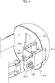
Figure 4 is a broken perspective view of the part of device indicated by the arrow IV inFigure 3 ; -
Figure 5 is a view in side elevation of a lighting device according to some embodiments, which exemplifies passage between the conditions illustrated inFigure 1 and inFigure 3 ; and -
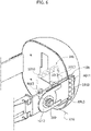
Figure 6 is a corresponding broken perspective view of the part of device indicated by the arrow VI inFigure 5 . - It will be appreciated that, for clarity and simplicity of illustration, the various figures may not be reproduced in the same scale.
- In the ensuing description various specific details are illustrated in order to enable an in-depth understanding of various examples of embodiments according to the disclosure. The embodiments may be obtained without one or more of the specific details, or with other methods, components, materials, etc. In other cases, known structures, materials, or operations are not illustrated or described in detail so that the various aspects of the embodiments will not be obscured.
- Reference to "an embodiment" or "one embodiment" in the framework of the present description is intended to indicate that a particular configuration, structure, or characteristic described in relation to the embodiment is comprised in at least one embodiment. Consequently, phrases such as "in an embodiment" or "in one embodiment" that may be present in various points of the present description do not necessarily refer exactly to one and the same embodiment. Moreover, particular conformations, structures, or characteristics may be combined in any adequate way in one or more embodiments.
- The references used herein are provided merely for convenience and hence do not define the sphere of protection or the scope of the embodiments.
- Once again for brevity and simplicity of treatment, and unless the context were to indicate otherwise, in the annexed figures parts or elements that are similar or identical are designated by the same references, without repeating the corresponding description for each figure.
- In
Figure 1 , thereference 10 designates as a whole a lighting device. - It may, for example, be a lighting device that can be used in the show-business and entertainment sector. As has already been said, this possible sector of use is mentioned herein purely by way of reference and should hence not be understood as in any way limiting the embodiments.
- According to a possible configuration (in itself known), the
device 10 comprises abase 12 for mounting on a supporting structure (not visible in the figures: it may, for example, be a stage structure in a theatre, in an arena, or on the site of a show), mounted on which is a fork-like support 14. - The fork-
like support 14 can be swivelled, for example through 360°, about an axis X14 (vertical in the figures) and supports with its arms or prongs amobile head 16, which can be oriented by a general movement of slewing about an axis X16 (horizontal in the figures). - Mounted in the
head 16 is a source of light radiation LS (for example, an RGB LED source) that is to produce an illuminating beam that exits from thehead 16 through afront optics 160, in a direction substantially aligned with a longitudinal axis of the mobile head, designated by X10. - The combined movement about the axes X14 and X16, governed via motor drives (not visible in the figures) arranged, for example, in the
base 12 and in the fork-like support 14 (i.e., in the head 16) leads the illuminating beam projected through thefront optics 160 to perform a movement of scanning that is able to cover a volume greater than a half-space. - As recalled previously, the overall structure of a
device 10 and the modalities of performance of the aforesaid scanning movement are to be deemed known in the art (for example, from the device AXCOR recalled at the outset of the present description), which renders any more detailed indications in the context of the present description superfluous. - This description chiefly regards providing, in such a
device 10, a pair ofhandles orientable head 16 and can be selectively located: - in a first position - horizontal, as viewed in the figures - retracted against the body of the
mobile head 16, as illustrated inFigures 1 and2 ; this position may be adopted, for example, when thedevice 10 is in its condition of use; and - in a second position - vertical, as viewed in the figures - in which the handles project, for example upwards, with respect to the body of the
mobile head 16 as illustrated inFigures 3 and4 ; this position may be adopted, for example, when thedevice 10 is being carried/handled. - Of course, reference to a "horizontal" position and a "vertical" position is made purely for simplicity of description and does not have any limiting character.
- It brings out, however, the fact that, in one or more embodiments:
- in the first position, illustrated in
Figures 1 and2 , the handles are retracted against the body of themobile head 16 in a condition of at least substantial alignment with the longitudinal axis X10; and - in the second position, illustrated in
Figures 3 and4 , the handles project from the body of themobile head 16 in a direction transverse with respect to the longitudinal axis. - In one or more embodiments, passage between the first and second positions can lead to a rotation by an angle substantially equal to 90° about an axis, such as the axis X16.
- The possible orientation between the two aforesaid positions is exemplified in
Figures 5 and6 , where in effect only thehandle 101 is visible (represented by a solid line in the position ofFigures 1 and2 and by a dashed line in the position ofFigures 3 and4 ). - It will be appreciated that, in the position of
Figures 1 , and2 thehandles head 16, without practically protruding beyond the outline of thehead 16 itself, hence without producing undesired shadows. - This occurs also in the case where the
handles cross section 1010, 1020 - possibly with an anatomical shape. - In one or more embodiments, the body of the
head 16 may have cavities for receiving said gripping portions with enlarged cross section. - Visible in the figures is just one of the aforesaid cavities, designated by 1011, which is to receive the top portion with enlarged
cross section 1010 of thehandle 101. - A similar cavity, which is not visible in the figures and is to receive the top portion with enlarged
cross section 1020 of thehandle 102 may be provided in a specularly symmetrical position on the body of thehead 16. - In one or more embodiments, the
handles head 16 in such a way that their point of constraint to the head 16 (and to thedevice 10 as a whole) corresponds to the axis X16. In this way, it is possible to enable the movement of swivelling of thehandles Figures 1 and2 and the position ofFigures 3 and4 to occur about the axis X16. - The axis X16 is the axis where the
fork 14 supports thehead 16, and about this axis the movement of slewing of thehead 16 with respect to thefork 14 is performed. - The axis X16 is located in a position at least approximately centroidal with respect to the head 16 (and to the
device 10 as a whole), i.e., at or in the proximity of the centre of gravity thereof. - Consequently, the fact that the point of gripping of the
handles device 10 as a whole) corresponds to the axis X16, which is located in a substantially centroidal position, facilitates gripping of thedevice 10 firmly and in conditions of substantial equilibrium. - The above is enabled by the provision of gripping formations - such as the
handles 101, 102 - that at the very least discourage anybody from attempting to get hold of the device in the region of the light-emission optics 160. -
Figures 2 ,4 , and6 highlight the fact that one or more embodiments can exploit the presence ofarticulation pins 160 already provided for mounting thehead 16 at the distal ends of the arms or prongs of thefork 14. - In one or more embodiments, the
handles 101 and 102 (in the figures, these characteristics are visible only for thehandle 101, but altogether similar characteristics may be provided in a specularly symmetrical position on the body of thehead 16 for the handle 102) may consequently comprise anannular plate 1012 fitted so that it can rotate about thepin 160. - From the
plate 1012 there depart twolateral branches 1013 of the handle coupled to the opposite ends of the top portion 1010 (possibly with enlarged cross section and/or an anatomical shape, with depressions for the fingers). - Advantageously, the
aforesaid lateral branches 1013 may be provided as thin filiform branches: this may, in fact, contribute to enabling thehandles head 16 in the position illustrated inFigures 1 and2 , not to have parts that protrude beyond the outline of thedevice 10. - The general ring structure of the
handles lateral branches 1013, without jeopardizing the strength of the handles themselves. - In summary, a lighting device (for example, 10) as illustrated herein may comprise:
- a mounting structure (for example, 12, 14),
- a mobile head (for example, 16) with a light source (for example, LS) arranged in said mobile head, the mobile head being carried by the mounting structure in a rotatable way about an axis of rotation (for example, X16); and
- a pair of handles (for example, 101, 102) that are mounted on opposite sides of the mobile head (16) and can swivel about said axis of rotation between:
- at least one first position (see, for example,
Figures 1 and2 ), in which the handles are retracted against the mobile head; and - at least one second position (see, for example,
Figures 3 and4 ), in which the handles projecting from the mobile head provide formations for gripping the device.
- at least one first position (see, for example,
- Whereas the description of embodiments provided herein by way of example refers for simplicity to a first position "of use" (represented in
Figure 1 and with a solid line inFigure 5 ) and a second, "carrying", position (represented inFigure 3 and with a dashed line inFigure 5 ), reference to "at least" one first position and/or one second position is intended to highlight the fact that - on the basis of the same criteria described and illustrated herein - in one or more embodiments it is possible to envisage for thehandles 101 the possibility of assuming more than one position "of use" and/or more than one "carrying" position. - In a lighting device as illustrated herein, the light source may be configured to emit light along a longitudinal axis (for example, X10) of the mobile head, and:
- in the (at least one) first position, the handles may be oriented in the direction of said longitudinal axis; and
- in the (at least one) second position, the handles may be oriented in a direction transverse to said longitudinal axis.
- In a lighting device as illustrated herein, the handles may be mounted on the mobile head so that they can swivel between said first position and said second position as a result of a rotation of approximately 90° with respect to said axis of rotation.
- In a lighting device as illustrated herein, the handles may comprise distal gripping portions (for example, 1010, 1020), and the mobile head may comprise cavities (for example, 1011) for receiving the distal gripping portions of the handles in said first position.
- In a lighting device as illustrated herein, the handles may comprise distal gripping portions having an enlarged cross section and/or having an anatomical shape.
- In a lighting device as illustrated herein, the handles may have an annular structure with:
- a proximal element (for example, 1012) fitted rotatably about said axis of rotation (for example, X16);
- a pair of lateral branches (for example, 1013) that extend from the proximal element on opposite sides of the proximal element with respect to said axis of rotation; and
- a distal gripping portion (for example, 1010, 1020) that spans said pair of lateral branches.
- In a lighting device as illustrated herein, said axis of rotation (for example, X16) may be located in a central (centroidal) position of the device, i.e., at or in the proximity of the centre of gravity of the device itself (not necessarily at the very barycentre with reference to the centre of mass).
- In a lighting device as illustrated herein, the mounting structure may comprise a base portion (for example, 12) and a fork-like portion (for example, 14) mounted on the base portion, with:
- the fork-like portion that carries (via its arms or prongs) the mobile head rotatably about said axis of rotation; and
- the fork-like portion that is mounted on the base portion rotatably about a further axis of rotation (for example, X14), said axis of rotation being transverse (for example, orthogonal) with respect to said further axis of rotation.
- Without prejudice to the underlying principles, the details of construction and the embodiments may vary, even significantly, with respect to what has been described herein purely by way of non-limiting example, without thereby departing from the sphere of protection and scope of the invention, as determined by the annexed claims.
LIST OF REFERENCE SIGNS Device 10 Base 12 Fork- like support 14 Axis of orientation X14 Mobile head 16 Axis of orientation X16 Light source LS Light- projection optics 160 Longitudinal axis X10 Handles 101, 102 Handle gripping portions 1010, 1020 Receiving cavity 1011 Handle base plate 1012 Lateral branches of handle 1013
Claims (9)
- A lighting device (10), comprising:a mounting structure (12, 14),a mobile head (16) with a light source (LS) arranged in said mobile head (16), the mobile head being carried by the mounting structure (12, 14) rotatably about an axis of rotation, anda pair of handles (101, 102) mounted on opposite sides of the mobile head (16) and swivelable about said axis of rotation (X16) between:at least one first position, wherein the handles (101, 102) are retracted against the mobile head (16), andat least one second position, wherein the handles (101, 102) project from the mobile head (16) providing gripping formations for the device (10).
- The lighting device (10) of claim 1, wherein the light source (LS) is configured to emit light along a longitudinal axis (X10) of the mobile head (16),
wherein:in the first position, the handles (101, 102) are oriented in the direction of said longitudinal axis (X10), andin the second position, the handles (101, 102) are oriented in a direction transverse to said longitudinal axis (X10). - The lighting device (10) of claim 1 or claim 2, wherein the handles (101, 102) are mounted on the mobile head (16) swivelable between said first position and said second position as a result of a rotation of approximately 90° with respect to said axis of rotation (X16) .
- The lighting device (10) of any of claims 1 to 3, wherein the handles (101, 102) comprise distal gripping portions (1010, 1020) and the mobile head (16) comprises cavities (1011) for receiving the distal gripping portions (1010, 1020) of the handles (101, 102) in said first position.
- The lighting device (10) of any of the preceding claims, wherein the handles (101, 102) comprise distal gripping portions (1010, 1020) having an enlarged crosssection.
- The lighting device (10) of any of the preceding claims, wherein the handles (101, 102) comprise anatomically shaped distal gripping portions (1010, 1020).
- The lighting device (10) of any of the preceding claims, wherein the handles (101, 102) have an annular structure with:a proximal element rotatably fitted about said axis of rotation (X16),a pair of lateral branches (1013) extending from the proximal element (1012) on opposite sides of the proximal element (1012) with respect to said axis of rotation (X16), anda distal gripping portion (1010, 1020) extending bridge-like between said pair of lateral branches (1013).
- The lighting device (10) of any of the preceding claims, wherein said axis of rotation (X16) is located in a central position of the device (10).
- The lighting device (10) of any of the preceding claims, wherein the mounting structure (12, 14) comprises a base portion (12) and a fork-like portion (14) mounted on the base portion (12),
wherein:the fork-like portion (14) carries the mobile head rotatable about said axis or rotation (X16), andthe fork-like portion (14) is mounted on the base portion (12) rotatably about a further axis of rotation (X14), said axis of rotation (X16) being transverse with respect to said further axis of rotation (X14).
Applications Claiming Priority (1)
| Application Number | Priority Date | Filing Date | Title |
|---|---|---|---|
| IT102021000004751A IT202100004751A1 (en) | 2021-03-01 | 2021-03-01 | LIGHTING DEVICE |
Publications (1)
| Publication Number | Publication Date |
|---|---|
| EP4060228A1 true EP4060228A1 (en) | 2022-09-21 |
Family
ID=75850541
Family Applications (1)
| Application Number | Title | Priority Date | Filing Date |
|---|---|---|---|
| EP22156794.4A Withdrawn EP4060228A1 (en) | 2021-03-01 | 2022-02-15 | Lighting device |
Country Status (3)
| Country | Link |
|---|---|
| EP (1) | EP4060228A1 (en) |
| CN (1) | CN217843702U (en) |
| IT (1) | IT202100004751A1 (en) |
Cited By (2)
| Publication number | Priority date | Publication date | Assignee | Title |
|---|---|---|---|---|
| EP4517167A1 (en) * | 2023-08-31 | 2025-03-05 | Guangzhou Haoyang Electronic Co., Ltd. | Reverse-lock hand holding assembly and stage light fixture having same |
| WO2025092321A1 (en) * | 2023-10-31 | 2025-05-08 | Guangzhou Haoyang Electronic Co., Ltd | Foldable handle and stage light fixture having same |
Citations (5)
| Publication number | Priority date | Publication date | Assignee | Title |
|---|---|---|---|---|
| EP2469157A1 (en) * | 2010-12-22 | 2012-06-27 | GLP German Light Products GmbH | Light apparatus with a movable or removable handle |
| US20150016127A1 (en) * | 2009-12-04 | 2015-01-15 | Production Resource Group Llc | Moving Light with Follow Spot |
| US20160010837A1 (en) * | 2014-07-10 | 2016-01-14 | Surefire Llc | Locking pin for a t-rail mount for a portable light and movable, lockable handles for the same |
| CN209622526U (en) * | 2019-04-30 | 2019-11-12 | 广州星迪智能光电科技有限公司 | A kind of handle-concealed structure and lamps and lanterns |
| CN212361729U (en) * | 2018-12-24 | 2021-01-15 | 陈惠晋 | Stage lamp with good protection performance |
-
2021
- 2021-03-01 IT IT102021000004751A patent/IT202100004751A1/en unknown
-
2022
- 2022-02-15 EP EP22156794.4A patent/EP4060228A1/en not_active Withdrawn
- 2022-03-01 CN CN202220422841.1U patent/CN217843702U/en active Active
Patent Citations (5)
| Publication number | Priority date | Publication date | Assignee | Title |
|---|---|---|---|---|
| US20150016127A1 (en) * | 2009-12-04 | 2015-01-15 | Production Resource Group Llc | Moving Light with Follow Spot |
| EP2469157A1 (en) * | 2010-12-22 | 2012-06-27 | GLP German Light Products GmbH | Light apparatus with a movable or removable handle |
| US20160010837A1 (en) * | 2014-07-10 | 2016-01-14 | Surefire Llc | Locking pin for a t-rail mount for a portable light and movable, lockable handles for the same |
| CN212361729U (en) * | 2018-12-24 | 2021-01-15 | 陈惠晋 | Stage lamp with good protection performance |
| CN209622526U (en) * | 2019-04-30 | 2019-11-12 | 广州星迪智能光电科技有限公司 | A kind of handle-concealed structure and lamps and lanterns |
Cited By (2)
| Publication number | Priority date | Publication date | Assignee | Title |
|---|---|---|---|---|
| EP4517167A1 (en) * | 2023-08-31 | 2025-03-05 | Guangzhou Haoyang Electronic Co., Ltd. | Reverse-lock hand holding assembly and stage light fixture having same |
| WO2025092321A1 (en) * | 2023-10-31 | 2025-05-08 | Guangzhou Haoyang Electronic Co., Ltd | Foldable handle and stage light fixture having same |
Also Published As
| Publication number | Publication date |
|---|---|
| IT202100004751A1 (en) | 2022-09-01 |
| CN217843702U (en) | 2022-11-18 |
Similar Documents
| Publication | Publication Date | Title |
|---|---|---|
| EP3221639B1 (en) | A moving head lamp | |
| US7001044B2 (en) | Multiple head worklight | |
| EP0295958B1 (en) | Mobile universal shop light | |
| CN217843702U (en) | Lighting device | |
| CN207298687U (en) | An architectural spotlight that is easy to switch angles | |
| US20120063127A1 (en) | Indirect Light Assembly | |
| US10941928B2 (en) | Carrying handle for an automated moving-mirror luminaire | |
| CN208011422U (en) | A LED flood light with convenient angle adjustment | |
| JP6787808B2 (en) | Lighting equipment for growing natural grass | |
| CN210804311U (en) | Notebook computer heat dissipation frame | |
| CN208011515U (en) | An angle-adjustable LED floodlight | |
| JP6401985B2 (en) | Balloon lighting system | |
| CN221724214U (en) | Stage combined lamp with adjustable full-range angle | |
| CN209091897U (en) | Device for stationary transport ventilator and transport bed having the same | |
| CN118346961A (en) | A lighting device for garden seedling cultivation | |
| CN216280868U (en) | LED projection lamp | |
| CN215112189U (en) | Military and civil dual-purpose lighting device capable of adjusting reflecting surface | |
| CN209926142U (en) | Adjusting and locking device for lamp decoration | |
| CN212600108U (en) | Transformer substation is with electrified switch bolt fastening device | |
| CN212204166U (en) | Light projector structure | |
| JP2016152797A (en) | Lighting device for raising natural turf | |
| US20080253137A1 (en) | Skid Device for Spotlights | |
| CN207687960U (en) | A kind of inspecting lamp | |
| CN216307560U (en) | Landscape garden uses light | |
| CN213394703U (en) | Self-locking stage lighting device |
Legal Events
| Date | Code | Title | Description |
|---|---|---|---|
| PUAI | Public reference made under article 153(3) epc to a published international application that has entered the european phase |
Free format text: ORIGINAL CODE: 0009012 |
|
| STAA | Information on the status of an ep patent application or granted ep patent |
Free format text: STATUS: THE APPLICATION HAS BEEN PUBLISHED |
|
| AK | Designated contracting states |
Kind code of ref document: A1 Designated state(s): AL AT BE BG CH CY CZ DE DK EE ES FI FR GB GR HR HU IE IS IT LI LT LU LV MC MK MT NL NO PL PT RO RS SE SI SK SM TR |
|
| RAP1 | Party data changed (applicant data changed or rights of an application transferred) |
Owner name: CLAY PAKY S.P.A. |
|
| STAA | Information on the status of an ep patent application or granted ep patent |
Free format text: STATUS: REQUEST FOR EXAMINATION WAS MADE |
|
| 17P | Request for examination filed |
Effective date: 20230221 |
|
| RBV | Designated contracting states (corrected) |
Designated state(s): AL AT BE BG CH CY CZ DE DK EE ES FI FR GB GR HR HU IE IS IT LI LT LU LV MC MK MT NL NO PL PT RO RS SE SI SK SM TR |
|
| P01 | Opt-out of the competence of the unified patent court (upc) registered |
Effective date: 20230525 |
|
| RAP1 | Party data changed (applicant data changed or rights of an application transferred) |
Owner name: CLAY PAKY S.R.L. |
|
| STAA | Information on the status of an ep patent application or granted ep patent |
Free format text: STATUS: EXAMINATION IS IN PROGRESS |
|
| STAA | Information on the status of an ep patent application or granted ep patent |
Free format text: STATUS: THE APPLICATION HAS BEEN WITHDRAWN |
|
| 17Q | First examination report despatched |
Effective date: 20240807 |
|
| 18W | Application withdrawn |
Effective date: 20240830 |