EP4060218B1 - Schirm-drehbasis für einen schirm - Google Patents
Schirm-drehbasis für einen schirm Download PDFInfo
- Publication number
- EP4060218B1 EP4060218B1 EP20889732.2A EP20889732A EP4060218B1 EP 4060218 B1 EP4060218 B1 EP 4060218B1 EP 20889732 A EP20889732 A EP 20889732A EP 4060218 B1 EP4060218 B1 EP 4060218B1
- Authority
- EP
- European Patent Office
- Prior art keywords
- pedal
- rotary
- disposed
- sleeve
- rotary base
- Prior art date
- Legal status (The legal status is an assumption and is not a legal conclusion. Google has not performed a legal analysis and makes no representation as to the accuracy of the status listed.)
- Active
Links
Images



Classifications
-
- E—FIXED CONSTRUCTIONS
- E04—BUILDING
- E04H—BUILDINGS OR LIKE STRUCTURES FOR PARTICULAR PURPOSES; SWIMMING OR SPLASH BATHS OR POOLS; MASTS; FENCING; TENTS OR CANOPIES, IN GENERAL
- E04H12/00—Towers; Masts or poles; Chimney stacks; Water-towers; Methods of erecting such structures
- E04H12/22—Sockets or holders for poles or posts
-
- E—FIXED CONSTRUCTIONS
- E04—BUILDING
- E04H—BUILDINGS OR LIKE STRUCTURES FOR PARTICULAR PURPOSES; SWIMMING OR SPLASH BATHS OR POOLS; MASTS; FENCING; TENTS OR CANOPIES, IN GENERAL
- E04H12/00—Towers; Masts or poles; Chimney stacks; Water-towers; Methods of erecting such structures
- E04H12/22—Sockets or holders for poles or posts
- E04H12/2238—Sockets or holders for poles or posts to be placed on the ground
-
- E—FIXED CONSTRUCTIONS
- E04—BUILDING
- E04H—BUILDINGS OR LIKE STRUCTURES FOR PARTICULAR PURPOSES; SWIMMING OR SPLASH BATHS OR POOLS; MASTS; FENCING; TENTS OR CANOPIES, IN GENERAL
- E04H12/00—Towers; Masts or poles; Chimney stacks; Water-towers; Methods of erecting such structures
- E04H12/22—Sockets or holders for poles or posts
- E04H12/2253—Mounting poles or posts to the holder
- E04H12/2276—Clamping poles or posts on a stub
-
- E—FIXED CONSTRUCTIONS
- E04—BUILDING
- E04H—BUILDINGS OR LIKE STRUCTURES FOR PARTICULAR PURPOSES; SWIMMING OR SPLASH BATHS OR POOLS; MASTS; FENCING; TENTS OR CANOPIES, IN GENERAL
- E04H12/00—Towers; Masts or poles; Chimney stacks; Water-towers; Methods of erecting such structures
- E04H12/22—Sockets or holders for poles or posts
- E04H12/2284—Means for adjusting the orientation of the post or pole
-
- F—MECHANICAL ENGINEERING; LIGHTING; HEATING; WEAPONS; BLASTING
- F16—ENGINEERING ELEMENTS AND UNITS; GENERAL MEASURES FOR PRODUCING AND MAINTAINING EFFECTIVE FUNCTIONING OF MACHINES OR INSTALLATIONS; THERMAL INSULATION IN GENERAL
- F16M—FRAMES, CASINGS OR BEDS OF ENGINES, MACHINES OR APPARATUS, NOT SPECIFIC TO ENGINES, MACHINES OR APPARATUS PROVIDED FOR ELSEWHERE; STANDS; SUPPORTS
- F16M11/00—Stands or trestles as supports for apparatus or articles placed thereon ; Stands for scientific apparatus such as gravitational force meters
- F16M11/02—Heads
- F16M11/04—Means for attachment of apparatus; Means allowing adjustment of the apparatus relatively to the stand
- F16M11/06—Means for attachment of apparatus; Means allowing adjustment of the apparatus relatively to the stand allowing pivoting
- F16M11/10—Means for attachment of apparatus; Means allowing adjustment of the apparatus relatively to the stand allowing pivoting around a horizontal axis
-
- A—HUMAN NECESSITIES
- A45—HAND OR TRAVELLING ARTICLES
- A45B—WALKING STICKS; UMBRELLAS; LADIES' OR LIKE FANS
- A45B23/00—Other umbrellas
- A45B2023/0012—Ground supported umbrellas or sunshades on a single post, e.g. resting in or on a surface there below
Definitions
- the present invention relates to the technical field of umbrellas, and relates to a seat for an umbrella, particularly to a rotary umbrella seat.
- umbrellas are widely applied in squares, beaches, parks, gardens or similar places to shield an individual from sun.
- the existing seats for umbrellas are in various forms and made of various materials. In order to maintain the balance between the seat and the canopy, the seat is relatively large or heavy.
- the seat commonly used at present is a fillable hollow seat body, and a handle insertion hole is formed in the seat body.
- the whole seat body is integrally formed by plastic injection molding.
- fillers such as water or fine sand are filled in the seat to balance the center of gravity of the seat, so that the seat is more stable after the handle is inserted into the seat.
- the seat with this structure is often large, heavy, inconvenient to transport, and high in the cost of manufacturing, packaging and transportation.
- the existing seats for umbrellas are fixed and cannot be rotated.
- a Chinese Utility Model Patent CN200720052619.2 disclosed an umbrella seat easy to fix a handle, comprising a fillable hollow seat body, characterized in that a connecting tube is inserted into an insertion hole in the center of the seat body; a handle sleeve is in threaded connection to the end of the connecting tube; the sleeve is of a two-layer structure; a plurality of through slots are formed on the sidewall of the inner-layer sleeve to form an elastic clamp ring; a plurality of threads are formed on the inner wall of the outer-layer sleeve; and, the tapered slope of the connecting tube cooperates with the elastic clamp ring of the handle sleeve to push the elastic clamp ring toward the inner side of the sleeve so as to fold and clamp the handle.
- CN 204 677 997 U discloses a rotatory umbrella shank of sun shade including bottom plate, base, umbrella pole, an umbrella shank section of thick bamboo and action bars, the base is located on the bottom plate and can be rotated by relative bottom plate, and the umbrella pole is fixed mutually with the base, and an umbrella shank section of thick bamboo stretches into in the umbrella pole and fixes on the bottom plate, the locating holes are distributed along the circumference on the bottom plate.
- CN 209 473 820 U discloses a sunshade umbrella, wherein the stand column connecting piece rotates in the circumferential direction relative to the umbrella base connecting piece, the first end of the pedal adjusting plate is connected with the stand column connecting piece through an elastic element, and the middle section of the pedal adjusting plate is hinged to the stand column connecting piece.
- the second end of the treading adjusting plate is provided with a positioning pin which penetrates through the stand column connecting piece and is selectively drilled into any positioning hole formed in the umbrella base connecting piece.
- a technical problem to be solved by the present invention is to provide a rotary umbrella seat, which is rational in structure and flexible and convenient to operate.
- the rotary umbrella seat is according to claim 1 such that it comprises a rotary base; a sleeve welding piece fitted through the rotary base; and a pedal component attached to the rotary base; characterized in that, the sleeve welding piece comprises a sleeve connected to a base plate; the sleeve is vertically post disposed in the middle of the base plate and is welded with the base plate; the rotary base is sleeved outside the sleeve and located above the base plate; a lower end of a column of the umbrella is slid over the sleeve and rest on the rotary base; the pedal component comprises a pedal connected to a pedal shaft; the pedal is resetably and rotatably attached to the top of the rotary base; the base plate has a plurality of positioning holes, the pedal shaft passes through the rotary base and is inserted into one of the positioning holes on the base plate, the pedal shaft is disengaged from the base plate when the pedal is pressed down during the
- the rotary base is a circular base with a hole formed in the central of the rotary base; the rotary base has a cylindrical boss formed at the hole of the rotary base; the lower end of the sleeve passes through an inner hole of the boss and is fixed to the base plate; a seat tube plug is disposed at the opening position on the top of the sleeve, and a rotary block is sleeved on the upper end of the sleeve; and the rotary block rotates with the column, and is rotatably sleeved on the upper end of the sleeve and is covered by the seat tube plug.
- the seat tube plug is a cylindrical structure matched with the inner hole of the sleeve; a flange resisted against the upper end face of the sleeve is disposed at the upper end of the seat tube plug, and a connecting pin hole is disposed radially at the lower end of the seat tube plug; a connecting hole is disposed on the sleeve, the seat tube plug is positioned to the sleeve by passing a limiting pin through the connecting hole and the connecting pin hole; an extension portion resisted against the lower end of the rotary block for limiting is disposed at the outer end of the limiting pin; and the rotary block is rotatably sleeved on the sleeve and is limited between the limiting pin and the flange of the seat tube plug.
- two mounting plates for mounting the pedal are disposed on the upper end of the rotary base, and one mounting hole is disposed close the outer ends of each mounting plate;
- two connecting lugs matched with the mounting plates are disposed at the lower end of the pedal, and two inner and two outer connecting holes are disposed on the connecting lugs;
- the outer connecting holes correspond to the mounting holes of the mounting plates;
- the pedal is capable of being rotatably mounted on the rotary base by passing a rotating shaft through the mounting holes of the mounting plates and the outer connecting holes of the connecting lugs; and a spring member capable of resetting the pedal is disposed between the pedal and the rotary base.
- a through hole for receiving the pedal shaft is longitudinally formed at a position, close to the inner side, in the middle of the rotary base between the two mounting plates; a pin hole is radially disposed at the upper end of the pedal shaft; the upper end of the pedal shaft is inserted between the two connecting lug of the pedal, and has a certain distance to the bottom of the pedal; the upper end of the pedal shaft is connected to the connecting lugs by passing a cylindrical pin through the inner connecting hole of the connecting lug, the pin hole and the connecting hole of the connecting lug on the other side; the plurality of positioning holes corresponding to the through hole of the rotary base for receiving and positioning the lower end of the pedal shaft are annularly disposed at intervals on the base plate close to the outer edge; and when the pedal is stepped down, the pedal shaft is driven by the pedal to move up to disengage from the positioning hole, and the rotary base can rotate freely.
- the spring member is a torsion spring
- the torsion spring is sleeved on the rotating shaft; and one end of the torsion spring is supported onto the upper end face of the rotary base, while the other end thereof is supported onto the rear end of the bottom of the pedal.
- a bent portion bent downward is disposed at the inner end of the pedal; when the pedal is reset, the bent portion is resisted against the upper end face of the rotary base, a protruded portion corresponding to the upper end of the pedal shaft is disposed on the lower end face of the pedal; when the pedal is stepped down and the pedal shaft is moved upward to disengage from the base plate, the protruded portion is resisted against the upper end of the pedal shaft, so as to limit the pedal when the pedal is stepped down to the largest extent.
- a groove for receiving the column is disposed on the rotary base along the outer side of the boss, the column is sleeved outside both the boss and the rotary block; the lower end of the column is inserted into the groove of the rotary base for positioning; the boss has the same shape as the rotary block, and a plurality of positioning guide ribs matched with the inner wall of the column are disposed on the outer circumferential surfaces of the boss and the rotary block.
- the present invention has the following advantages.
- the sleeve welding piece plays a role in fixation and supporting
- the rotary base plays a role in driving the rotation of the column
- the pedal plays a role in engaging or disengaging the rotary base from the sleeve welding piece through the pedal shaft.
- the pedal shaft is disengaged from the sleeve welding piece as long as the pedal is stepped down, so that the rotary base can be rotated, and the column is also rotated.
- the present invention is simple in structure, easy to operate, stable and reliable to use, and can easily realize the rotation of the seat so as to adjust the position of the umbrella, so it is worth popularizing.
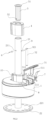
- a rotary umbrella seat comprises a rotary base 1, a sleeve welding piece 2 and a pedal component 3.
- the sleeve welding piece 2 at least comprises a sleeve 21 and a base plate 22.
- the sleeve 21 is a hollow tube, and is vertically post disposed in the middle of the base plate 22 to be welded and fixed to the base plate 22.
- the rotary base 1 is a circular base with a hole formed in its middle.
- the rotary base 1 is sleeved outside the sleeve 21 and located above the base plate 22; a lower end of a column 20 of the umbrella is slid over the sleeve 21 and rest on the rotary base 1;
- the pedal component 3 comprises a pedal 31 connected to a pedal shaft 32; the pedal 31 is resetably and rotatably attached to the top of the rotary base 1;
- the base plate 22 has a plurality of positioning holes 221, the pedal shaft 32 passes through the rotary base 1 and is inserted into one of the positioning holes 221 on the base plate 22, the pedal shaft 32 is disengaged from the base plate 22 when the pedal is pressed down during the rotation of the pedal 31, the pedal shaft is engaged to the rotary base when the pedal is released.
- the rotary base 1 has a cylindrical boss 10 formed at the hole of the rotary base 1; the lower end of the sleeve 21 passes through an inner hole of the boss 10 and is fixed to the base plate 22.
- a groove for receiving the column 20 is disposed on the rotary base 1 along the outer side of the boss 10.
- a seat tube plug 5 is disposed at the opening position on the top of the sleeve 21.
- the seat tube plug 5 is a cylindrical structure matched with the inner hole of the sleeve 21; a flange 51 resisted against the upper end face of the sleeve 21 is disposed at the upper end of the seat tube plug 5.
- a rotary block 4 is sleeved on the upper end of the sleeve 21, and the rotary block 4 has the same shape as the boss 10.
- the column 20 is sleeved outside both the boss 10 and the rotary block 4; the lower end of the column 20 is inserted into the groove of the rotary base 1 for positioning.
- a plurality of positioning guide ribs matched with the inner wall of the column 20 are disposed on the outer circumferential surfaces of the boss 10 and the rotary block 4.
- the rotary block 4 can rotate with the column 20.
- a connecting pin hole 52 is disposed radially at the lower end of the seat tube plug 5; a connecting hole 211 is disposed on the sleeve 21, the seat tube plug 5 is positioned to the sleeve 21 by passing a limiting pin 6 through the connecting hole 211 and the connecting pin hole 52; an extension portion resisted against the lower end of the rotary block 4 for limiting is disposed at the outer end of the limiting pin 6; and the rotary block 4 is rotatably sleeved on the sleeve 21 and is limited between the limiting pin 6 and the flange 51 of the seat tube plug 5.
- Two mounting plates 11 for mounting the pedal 31 are disposed on the upper end of the rotary base 1, and one mounting hole 111 is disposed close the outer ends of each mounting plate 11; two connecting lugs 311 matched with the mounting plates 11 are disposed at the lower end of the pedal 31, and two inner and two outer connecting holes 312,313 are disposed on the connecting lugs 311; the outer connecting holes 313 correspond to the mounting holes 111 of the mounting plates 11; the pedal 31 is capable of being rotatably mounted on the rotary base 1 by passing a rotating shaft 8 through the mounting holes 111 of the mounting plates 11 and the outer connecting holes 313 of the connecting lugs 311.
- a through hole for receiving the pedal shaft 32 is longitudinally formed at a position, close to the inner side, in the middle of the rotary base 1 between the two mounting plates 11; a pin hole 321 is radially disposed at the upper end of the pedal shaft 311; the upper end of the pedal shaft 32 is inserted between the two connecting lug 311 of the pedal 31, and has a certain distance to the bottom of the pedal 31; the upper end of the pedal shaft 32 is connected to the connecting lugs 311 by passing a cylindrical pin 9 through the inner connecting hole 312 of the connecting lug 311, the pin hole 321 and the connecting hole 312 of the connecting lug 311 on the other side; the plurality of positioning holes 221 corresponding to the through hole of the rotary base 1 for receiving and positioning the lower end of the pedal shaft 32 are annularly disposed at intervals on the base plate 22 close to the outer edge; and when the pedal 31 is stepped down, the pedal shaft 32 is driven by the pedal 31 to move up to disengage from the positioning hole 221, and the rotary base 1 can rotate
- a spring member capable of resetting the pedal 31 is disposed between the pedal 31 and the rotary base 1.
- the spring member is a torsion spring 7, the torsion spring 7 is sleeved on the rotating shaft 8; and one end of the torsion spring 7 is supported onto the upper end face of the rotary base 1, while the other end thereof is supported onto the rear end of the bottom of the pedal 31.
- the petal 31 has a trend to rotate upward all the time so that the pedal shaft 32 is inserted into the positioning hole 221 of the base plate 22.
- a bent portion 314 bent downward is disposed at the inner end of the pedal 31; when the pedal 31 is reset, the bent portion 314 is resisted against the upper end face of the rotary base 1, a protruded portion 315 corresponding to the upper end of the pedal shaft 32 is disposed on the lower end face of the pedal 31; when the pedal 31 is stepped down and the pedal shaft 32 is moved upward to disengage from the base plate 22, the protruded portion 315 is resisted against the upper end of the pedal shaft 32, so as to limit the pedal 31 when the pedal 31 is stepped down to the largest extent.
- the pedal 31 When it is necessary to rotate the seat, the pedal 31 is stepped down, and the cylindrical pin 9 drives the petal shaft 32 to move upward to disengage from the base plate 22 of the sleeve welding piece 2.
- the protruded portion 315 on the inner side comes into contact with the upper surface of the pedal shaft 32, and the pedal 31 is stepped down to the largest extent.
- the boss 10 of the rotary base 1 has the same shape as the rotary block 4, and the external column 20 is sleeved on both the rotary base 1 and the rotary block 4.
- the pedal 31 is released.
- the pedal 31 is reset due to the action of the torsion spring 7, and the pedal shaft 32 is moved down to be inserted into the positioning hole 221 of the base plate 22.
- the bent portion 314 at the front end of the pedal 31 is resisted against the upper surface of the rotary base 1 to position and lock the seat, as shown in Fig. 4 .
Landscapes
- Engineering & Computer Science (AREA)
- Architecture (AREA)
- Civil Engineering (AREA)
- Structural Engineering (AREA)
- General Engineering & Computer Science (AREA)
- Mechanical Engineering (AREA)
- Walking Sticks, Umbrellas, And Fans (AREA)
Claims (7)
- Drehbarer Schirmsitz für einen Regenschirm, bestehend aus:einer Drehbasis (1);einem Muffenschweißstück (2), das durch die Drehbasis eingepasst ist; undeiner Pedalkomponente (3), die an der Drehbasis befestigt ist;wobei das Muffenschweißstück (2) eine mit einer Grundplatte (22) verbundene Hülse (21) umfasst;die Hülse (21) ein vertikaler Pfosten ist, der in der Mitte der Grundplatte (22) angeordnet und mit der Grundplatte verschweißt ist;die Drehbasis (1) die Außenseite der Hülse (21) umhüllt und über der Grundplatte (22) angeordnet ist;sodass ein unteres Ende einer Säule (20) des Schirms über die Hülse (21) verschiebbar ist und auf der Drehbasis zu liegen kommt;der genannte drehbare Schirmsitz außerdem eine Pedalkomponente mit einem Pedal (31) umfasst, das mit einer Pedalwelle (32) verbunden ist;das Pedal rücksetzbar und drehbar an der Oberseite der Drehbasis (1) befestigt ist;die Grundplatte (22) mehrere Positionierungslöcher (221) auf weist, die Pedalwelle (32) durch die Drehbasis (1) verläuft und in eines der Positionierungslöcher (221) der Grundplatte (22) eingeführt wird, sodass die Pedalwelle (32) von der Grundplatte (22) gelöst wird, wenn das Pedal während der Pedaldrehung nach unten gedrückt wird,und die Pedalwelle (32) mit der Drehbasis (1) in Eingriff steht, wenn das Pedal losgelassen wird;wobei die Drehbasis (1) eine kreisförmige Basis mit einem in der Mitte der Drehbasis ausgebildeten Loch ist;die Drehbasis einen zylindrischen Vorsprung (10) aufweist, der am Loch der Drehbasis ausgebildet ist;das untere Ende der Hülse (21) durch ein Innenloch des Vorsprungs (10) verläuft und an der Grundplatte (22) befestigt ist;der drehbare Schirmsitz weiterhin einen Sitzrohrstopfen (5) umfasst, der an einer Öffnungsposition an der Oberseite der Hülse (21) angeordnet ist, und ein Drehblock (4) das obere Ende der Hülse umhüllt; sodass der Drehblock (4) dazu geeignet ist, sich mit der Säule (20) zu drehen, drehbar das obere Ende der Hülse (21) umhüllt und vom Sitzrohrstopfen (5) abgedeckt wird.
- Schirmsitz nach Anspruch 1, dadurch gekennzeichnet, dass der Sitzrohrstopfen eine zylindrische Struktur ist, die mit dem Innenloch der Hülse zusammenpasst;am oberen Ende des Sitzrohrstopfens ein Flansch (51) angeordnet ist, der gegen die obere Endfläche der Hülse stößt, und am unteren Ende des Sitzrohrstopfens radial ein Verbindungsstiftloch (52) angeordnet ist;an der Hülse ein Verbindungsloch angeordnet ist, der Sitzrohrstopfen an der Hülse positioniert wird, indem ein Begrenzungsstift (6) durch das Verbindungsloch und das Verbindungsstiftloch geführt wird;ein Verlängerungsabschnitt, der gegen das untere Ende des Drehblocks stößt, zur Begrenzung am äußeren Ende des Begrenzungsstifts angeordnet ist; undder Drehblock die Hülse drehbar umhüllt und zwischen dem Begrenzungsstift und dem Flansch des Sitzrohrstopfens begrenzt wird.
- Schirmsitz nach Anspruch 1, dadurch gekennzeichnet, dass zwei Montageplatten (11) zur Montage des Pedals am oberen Ende der Drehbasis angeordnet sind und ein Montageloch (111) nahe den äußeren Enden jeder Montageplatte angeordnet ist;am unteren Ende des Pedals zwei zu den Montageplatten passende Verbindungslaschen (311) angeordnet sind, und an den Verbindungslaschen zwei innere und zwei äußere Verbindungslöcher (312, 313) angeordnet sind;die äußeren Verbindungslöcher den Montagelöchern (111) der Montageplatten entsprechen;das Pedal drehbar auf der Drehbasis montiert werden kann, indem eine Drehwelle (8) durch die Montagelöcher der Montageplatten und die äußeren Verbindungslöcher der Verbindungslaschen geführt wird; undzwischen dem Pedal und der Drehbasis ein Federelement angeordnet ist, das das Pedal zurückstellen kann.
- Schirmsitz nach Anspruch 3, dadurch gekennzeichnet, dass ein Durchgangsloch zur Aufnahme der Pedalwelle in Längsrichtung an einer Position nahe der Innenseite in der Mitte der Drehbasis zwischen den beiden Montageplatten ausgebildet ist;ein Stiftloch (321) radial am oberen Ende der Pedalwelle angeordnet ist;das obere Ende der Pedalwelle zwischen die beiden Verbindungslaschen des Pedals eingeführt wird und einen gewissen Abstand zur Unterseite des Pedals aufweist;das obere Ende der Pedalwelle mit den Verbindungslaschen verbunden wird, indem ein zylindrischer Stift (9) durch das innere Verbindungsloch der Verbindungslasche, das Stiftloch und das Verbindungsloch der Verbindungslasche auf der anderen Seite geführt wird;die mehreren Positionierungslöcher (221), die dem Durchgangsloch der Drehbasis zum Aufnehmen und Positionieren des unteren Endes der Pedalwelle entsprechen, ringförmig in Abständen auf der Basisplatte nahe der Außenkante angeordnet sind; undwenn das Pedal nach unten getreten wird, sich die Pedalwelle durch das Pedal nach oben bewegt und sich vom Positionierungsloch löst, sodass sich die Drehbasis frei drehen kann.
- Schirmsitz nach Anspruch 4, dadurch gekennzeichnet, dass das Federelement eine Torsionsfeder (7) ist, wobei die Torsionsfeder die Drehwelle umhüllt; und
ein Ende der Torsionsfeder auf der oberen Endfläche der Drehbasis abgestützt wird, während das andere Ende davon auf dem hinteren Ende der Unterseite des Pedals abgestützt wird. - Schirmsitz nach Anspruch 5, dadurch gekennzeichnet, dass am inneren Ende des Pedals ein nach unten gebogener Abschnitt (314) angeordnet ist;wenn das Pedal zurückgesetzt wird, der gebogene Abschnitt gegen die obere Endfläche der Drehbasis stößt, ein vorstehender Abschnitt (315), der dem oberen Ende der Pedalwelle entspricht, an der unteren Endfläche des Pedals angeordnet ist;wenn das Pedal nach unten getreten wird und die Pedalwelle nach oben bewegt wird, um sich von der Grundplatte zu lösen, der vorstehende Abschnitt gegen das obere Ende der Pedalwelle drückt, um so das Pedal zu begrenzen, wenn das Pedal bis zum größten Ausmaß nach unten getreten wird.
- Schirmsitz nach einem der Ansprüche 1 - 6, dadurch gekennzeichnet, dass eine Nut zur Aufnahme der Säule auf der Drehbasis entlang der Außenseite des Vorsprungs angeordnet ist und die Säule sowohl die Außenseite des Vorsprungs als auch die des Drehblocks umhüllt;das untere Ende der Säule zur Positionierung in die Nut der Drehbasis eingeführt wird;der Vorsprung die gleiche Form wie der Drehblock aufweist, und an den Außenumfangsflächen des Vorsprungs und des Drehblocks mehrere Positionierungsführungsrippen angebracht sind, die an die Innenwand der Säule angepasst sind.
Applications Claiming Priority (2)
| Application Number | Priority Date | Filing Date | Title |
|---|---|---|---|
| CN201922016648.9U CN211483233U (zh) | 2019-11-20 | 2019-11-20 | 一种旋转伞座 |
| PCT/CN2020/072346 WO2021098037A1 (zh) | 2019-11-20 | 2020-01-16 | 一种旋转伞座 |
Publications (3)
| Publication Number | Publication Date |
|---|---|
| EP4060218A1 EP4060218A1 (de) | 2022-09-21 |
| EP4060218A4 EP4060218A4 (de) | 2022-12-28 |
| EP4060218B1 true EP4060218B1 (de) | 2024-05-01 |
Family
ID=72410529
Family Applications (1)
| Application Number | Title | Priority Date | Filing Date |
|---|---|---|---|
| EP20889732.2A Active EP4060218B1 (de) | 2019-11-20 | 2020-01-16 | Schirm-drehbasis für einen schirm |
Country Status (4)
| Country | Link |
|---|---|
| US (1) | US11959293B2 (de) |
| EP (1) | EP4060218B1 (de) |
| CN (1) | CN211483233U (de) |
| WO (1) | WO2021098037A1 (de) |
Families Citing this family (2)
| Publication number | Priority date | Publication date | Assignee | Title |
|---|---|---|---|---|
| CN116172324A (zh) * | 2023-02-10 | 2023-05-30 | 江苏辉腾休闲用品有限公司 | 一种遮阳伞的滑动把手装置 |
| CN116906991B (zh) * | 2023-06-28 | 2024-10-11 | 广东英为拓科技有限公司 | 一种可旋转稳定型转轮除湿机 |
Family Cites Families (11)
| Publication number | Priority date | Publication date | Assignee | Title |
|---|---|---|---|---|
| US6511033B2 (en) * | 2000-05-10 | 2003-01-28 | Wanda Ying Li | Rotation locker stand for outdoor umbrellas |
| CN2600685Y (zh) * | 2003-01-28 | 2004-01-21 | 陈逢春 | 旋转伞座角度自锁装置 |
| US8672287B2 (en) * | 2007-05-29 | 2014-03-18 | Oliver Joen-An Ma | Adjustable rotation base |
| US7836902B2 (en) * | 2009-02-18 | 2010-11-23 | Benson Tung | Sunshade having base |
| CN201982912U (zh) * | 2010-04-15 | 2011-09-21 | 赵立峰 | 遮阳伞的脚踏式伞座 |
| US9957728B2 (en) * | 2013-09-19 | 2018-05-01 | Oliver Joen-An Ma | Rotation base for umbrella |
| US9155364B2 (en) * | 2013-10-24 | 2015-10-13 | Mario Jason | Sunshade positioning device |
| CN204677997U (zh) * | 2015-04-02 | 2015-09-30 | 宁波佳信旅游用品有限公司 | 一种遮阳伞的旋转伞座 |
| CN205624856U (zh) * | 2016-05-18 | 2016-10-12 | 杭州中艺实业股份有限公司 | 一种立柱旋转锁定结构 |
| CN109043759A (zh) * | 2018-10-16 | 2018-12-21 | 台州博旅达工艺品有限公司 | 遮阳伞旋转机构 |
| CN209473820U (zh) * | 2018-11-02 | 2019-10-11 | 宁波万汇休闲用品有限公司 | 一种遮阳伞 |
-
2019
- 2019-11-20 CN CN201922016648.9U patent/CN211483233U/zh active Active
-
2020
- 2020-01-16 US US17/755,031 patent/US11959293B2/en active Active
- 2020-01-16 WO PCT/CN2020/072346 patent/WO2021098037A1/zh not_active Ceased
- 2020-01-16 EP EP20889732.2A patent/EP4060218B1/de active Active
Also Published As
| Publication number | Publication date |
|---|---|
| US11959293B2 (en) | 2024-04-16 |
| CN211483233U (zh) | 2020-09-15 |
| US20220389732A1 (en) | 2022-12-08 |
| EP4060218A4 (de) | 2022-12-28 |
| WO2021098037A1 (zh) | 2021-05-27 |
| EP4060218A1 (de) | 2022-09-21 |
Similar Documents
| Publication | Publication Date | Title |
|---|---|---|
| US7318444B2 (en) | Hub assembly for an umbrella frame | |
| US6869058B2 (en) | Base assembly for a sunshade | |
| US6007032A (en) | Foldable stand assembly for microphones | |
| CN105725403B (zh) | 一种可左右调节角度的遮阳伞 | |
| GB2331464A (en) | Telescopic shaft for clubs | |
| US11959293B2 (en) | Rotary umbrella seat for an umbrella | |
| CN207901017U (zh) | 一种螺丝刀 | |
| US6401736B1 (en) | Umbrella device with engaging mechanism | |
| CN113907498A (zh) | 一种用于遮阳伞的旋转机构及遮阳伞 | |
| US6920888B2 (en) | Foldable stick assembly | |
| US20130165303A1 (en) | Exercise device | |
| KR101288634B1 (ko) | 낚시대 받침지주의 회전 록킹구조 | |
| CN205162164U (zh) | 一种遮阳伞的定位机构 | |
| US5276271A (en) | Music box motion generation mechanism | |
| KR101651323B1 (ko) | 파라솔의 각도 조절장치 | |
| US5320594A (en) | Multipurpose gymnastic apparatus | |
| CN211327979U (zh) | 一种可收折跑步机 | |
| US7322765B2 (en) | Stick container | |
| CN211574838U (zh) | 一种台灯 | |
| KR102037566B1 (ko) | 파라솔의 각도 조절장치 | |
| CN216723473U (zh) | 一种用于遮阳伞的旋转机构及遮阳伞 | |
| CN210353521U (zh) | 一种手动旋转折角式方管户外中柱伞 | |
| KR200468428Y1 (ko) | 편심 파라솔용 기둥 | |
| CN208739175U (zh) | 一种多功能手机调节支架 | |
| KR200411422Y1 (ko) | 회전우산의 구조 |
Legal Events
| Date | Code | Title | Description |
|---|---|---|---|
| STAA | Information on the status of an ep patent application or granted ep patent |
Free format text: STATUS: THE INTERNATIONAL PUBLICATION HAS BEEN MADE |
|
| PUAI | Public reference made under article 153(3) epc to a published international application that has entered the european phase |
Free format text: ORIGINAL CODE: 0009012 |
|
| STAA | Information on the status of an ep patent application or granted ep patent |
Free format text: STATUS: REQUEST FOR EXAMINATION WAS MADE |
|
| 17P | Request for examination filed |
Effective date: 20220617 |
|
| AK | Designated contracting states |
Kind code of ref document: A1 Designated state(s): AL AT BE BG CH CY CZ DE DK EE ES FI FR GB GR HR HU IE IS IT LI LT LU LV MC MK MT NL NO PL PT RO RS SE SI SK SM TR |
|
| A4 | Supplementary search report drawn up and despatched |
Effective date: 20221124 |
|
| RIC1 | Information provided on ipc code assigned before grant |
Ipc: E04H 12/22 20060101ALI20221118BHEP Ipc: A45B 23/00 20060101ALI20221118BHEP Ipc: F16M 11/10 20060101AFI20221118BHEP |
|
| DAV | Request for validation of the european patent (deleted) | ||
| DAX | Request for extension of the european patent (deleted) | ||
| GRAP | Despatch of communication of intention to grant a patent |
Free format text: ORIGINAL CODE: EPIDOSNIGR1 |
|
| STAA | Information on the status of an ep patent application or granted ep patent |
Free format text: STATUS: GRANT OF PATENT IS INTENDED |
|
| INTG | Intention to grant announced |
Effective date: 20240206 |
|
| GRAS | Grant fee paid |
Free format text: ORIGINAL CODE: EPIDOSNIGR3 |
|
| GRAA | (expected) grant |
Free format text: ORIGINAL CODE: 0009210 |
|
| STAA | Information on the status of an ep patent application or granted ep patent |
Free format text: STATUS: THE PATENT HAS BEEN GRANTED |
|
| AK | Designated contracting states |
Kind code of ref document: B1 Designated state(s): AL AT BE BG CH CY CZ DE DK EE ES FI FR GB GR HR HU IE IS IT LI LT LU LV MC MK MT NL NO PL PT RO RS SE SI SK SM TR |
|
| REG | Reference to a national code |
Ref country code: GB Ref legal event code: FG4D |
|
| REG | Reference to a national code |
Ref country code: CH Ref legal event code: EP |
|
| REG | Reference to a national code |
Ref country code: IE Ref legal event code: FG4D |
|
| REG | Reference to a national code |
Ref country code: DE Ref legal event code: R096 Ref document number: 602020030425 Country of ref document: DE |
|
| REG | Reference to a national code |
Ref country code: NL Ref legal event code: FP |
|
| REG | Reference to a national code |
Ref country code: LT Ref legal event code: MG9D |
|
| PG25 | Lapsed in a contracting state [announced via postgrant information from national office to epo] |
Ref country code: IS Free format text: LAPSE BECAUSE OF FAILURE TO SUBMIT A TRANSLATION OF THE DESCRIPTION OR TO PAY THE FEE WITHIN THE PRESCRIBED TIME-LIMIT Effective date: 20240901 |
|
| PG25 | Lapsed in a contracting state [announced via postgrant information from national office to epo] |
Ref country code: BG Free format text: LAPSE BECAUSE OF FAILURE TO SUBMIT A TRANSLATION OF THE DESCRIPTION OR TO PAY THE FEE WITHIN THE PRESCRIBED TIME-LIMIT Effective date: 20240501 |
|
| PG25 | Lapsed in a contracting state [announced via postgrant information from national office to epo] |
Ref country code: FI Free format text: LAPSE BECAUSE OF FAILURE TO SUBMIT A TRANSLATION OF THE DESCRIPTION OR TO PAY THE FEE WITHIN THE PRESCRIBED TIME-LIMIT Effective date: 20240501 Ref country code: HR Free format text: LAPSE BECAUSE OF FAILURE TO SUBMIT A TRANSLATION OF THE DESCRIPTION OR TO PAY THE FEE WITHIN THE PRESCRIBED TIME-LIMIT Effective date: 20240501 |
|
| PG25 | Lapsed in a contracting state [announced via postgrant information from national office to epo] |
Ref country code: GR Free format text: LAPSE BECAUSE OF FAILURE TO SUBMIT A TRANSLATION OF THE DESCRIPTION OR TO PAY THE FEE WITHIN THE PRESCRIBED TIME-LIMIT Effective date: 20240802 |
|
| PG25 | Lapsed in a contracting state [announced via postgrant information from national office to epo] |
Ref country code: PT Free format text: LAPSE BECAUSE OF FAILURE TO SUBMIT A TRANSLATION OF THE DESCRIPTION OR TO PAY THE FEE WITHIN THE PRESCRIBED TIME-LIMIT Effective date: 20240902 |
|
| REG | Reference to a national code |
Ref country code: AT Ref legal event code: MK05 Ref document number: 1682789 Country of ref document: AT Kind code of ref document: T Effective date: 20240501 |
|
| PG25 | Lapsed in a contracting state [announced via postgrant information from national office to epo] |
Ref country code: ES Free format text: LAPSE BECAUSE OF FAILURE TO SUBMIT A TRANSLATION OF THE DESCRIPTION OR TO PAY THE FEE WITHIN THE PRESCRIBED TIME-LIMIT Effective date: 20240501 |
|
| PG25 | Lapsed in a contracting state [announced via postgrant information from national office to epo] |
Ref country code: AT Free format text: LAPSE BECAUSE OF FAILURE TO SUBMIT A TRANSLATION OF THE DESCRIPTION OR TO PAY THE FEE WITHIN THE PRESCRIBED TIME-LIMIT Effective date: 20240501 |
|
| PG25 | Lapsed in a contracting state [announced via postgrant information from national office to epo] |
Ref country code: PL Free format text: LAPSE BECAUSE OF FAILURE TO SUBMIT A TRANSLATION OF THE DESCRIPTION OR TO PAY THE FEE WITHIN THE PRESCRIBED TIME-LIMIT Effective date: 20240501 |
|
| PG25 | Lapsed in a contracting state [announced via postgrant information from national office to epo] |
Ref country code: LV Free format text: LAPSE BECAUSE OF FAILURE TO SUBMIT A TRANSLATION OF THE DESCRIPTION OR TO PAY THE FEE WITHIN THE PRESCRIBED TIME-LIMIT Effective date: 20240501 |
|
| PG25 | Lapsed in a contracting state [announced via postgrant information from national office to epo] |
Ref country code: PT Free format text: LAPSE BECAUSE OF FAILURE TO SUBMIT A TRANSLATION OF THE DESCRIPTION OR TO PAY THE FEE WITHIN THE PRESCRIBED TIME-LIMIT Effective date: 20240902 Ref country code: PL Free format text: LAPSE BECAUSE OF FAILURE TO SUBMIT A TRANSLATION OF THE DESCRIPTION OR TO PAY THE FEE WITHIN THE PRESCRIBED TIME-LIMIT Effective date: 20240501 Ref country code: NO Free format text: LAPSE BECAUSE OF FAILURE TO SUBMIT A TRANSLATION OF THE DESCRIPTION OR TO PAY THE FEE WITHIN THE PRESCRIBED TIME-LIMIT Effective date: 20240801 Ref country code: LV Free format text: LAPSE BECAUSE OF FAILURE TO SUBMIT A TRANSLATION OF THE DESCRIPTION OR TO PAY THE FEE WITHIN THE PRESCRIBED TIME-LIMIT Effective date: 20240501 Ref country code: IS Free format text: LAPSE BECAUSE OF FAILURE TO SUBMIT A TRANSLATION OF THE DESCRIPTION OR TO PAY THE FEE WITHIN THE PRESCRIBED TIME-LIMIT Effective date: 20240901 Ref country code: HR Free format text: LAPSE BECAUSE OF FAILURE TO SUBMIT A TRANSLATION OF THE DESCRIPTION OR TO PAY THE FEE WITHIN THE PRESCRIBED TIME-LIMIT Effective date: 20240501 Ref country code: GR Free format text: LAPSE BECAUSE OF FAILURE TO SUBMIT A TRANSLATION OF THE DESCRIPTION OR TO PAY THE FEE WITHIN THE PRESCRIBED TIME-LIMIT Effective date: 20240802 Ref country code: FI Free format text: LAPSE BECAUSE OF FAILURE TO SUBMIT A TRANSLATION OF THE DESCRIPTION OR TO PAY THE FEE WITHIN THE PRESCRIBED TIME-LIMIT Effective date: 20240501 Ref country code: ES Free format text: LAPSE BECAUSE OF FAILURE TO SUBMIT A TRANSLATION OF THE DESCRIPTION OR TO PAY THE FEE WITHIN THE PRESCRIBED TIME-LIMIT Effective date: 20240501 Ref country code: BG Free format text: LAPSE BECAUSE OF FAILURE TO SUBMIT A TRANSLATION OF THE DESCRIPTION OR TO PAY THE FEE WITHIN THE PRESCRIBED TIME-LIMIT Effective date: 20240501 Ref country code: AT Free format text: LAPSE BECAUSE OF FAILURE TO SUBMIT A TRANSLATION OF THE DESCRIPTION OR TO PAY THE FEE WITHIN THE PRESCRIBED TIME-LIMIT Effective date: 20240501 Ref country code: RS Free format text: LAPSE BECAUSE OF FAILURE TO SUBMIT A TRANSLATION OF THE DESCRIPTION OR TO PAY THE FEE WITHIN THE PRESCRIBED TIME-LIMIT Effective date: 20240801 |
|
| PG25 | Lapsed in a contracting state [announced via postgrant information from national office to epo] |
Ref country code: DK Free format text: LAPSE BECAUSE OF FAILURE TO SUBMIT A TRANSLATION OF THE DESCRIPTION OR TO PAY THE FEE WITHIN THE PRESCRIBED TIME-LIMIT Effective date: 20240501 |
|
| PG25 | Lapsed in a contracting state [announced via postgrant information from national office to epo] |
Ref country code: EE Free format text: LAPSE BECAUSE OF FAILURE TO SUBMIT A TRANSLATION OF THE DESCRIPTION OR TO PAY THE FEE WITHIN THE PRESCRIBED TIME-LIMIT Effective date: 20240501 |
|
| PG25 | Lapsed in a contracting state [announced via postgrant information from national office to epo] |
Ref country code: CZ Free format text: LAPSE BECAUSE OF FAILURE TO SUBMIT A TRANSLATION OF THE DESCRIPTION OR TO PAY THE FEE WITHIN THE PRESCRIBED TIME-LIMIT Effective date: 20240501 |
|
| PG25 | Lapsed in a contracting state [announced via postgrant information from national office to epo] |
Ref country code: RO Free format text: LAPSE BECAUSE OF FAILURE TO SUBMIT A TRANSLATION OF THE DESCRIPTION OR TO PAY THE FEE WITHIN THE PRESCRIBED TIME-LIMIT Effective date: 20240501 Ref country code: SK Free format text: LAPSE BECAUSE OF FAILURE TO SUBMIT A TRANSLATION OF THE DESCRIPTION OR TO PAY THE FEE WITHIN THE PRESCRIBED TIME-LIMIT Effective date: 20240501 |
|
| PG25 | Lapsed in a contracting state [announced via postgrant information from national office to epo] |
Ref country code: SM Free format text: LAPSE BECAUSE OF FAILURE TO SUBMIT A TRANSLATION OF THE DESCRIPTION OR TO PAY THE FEE WITHIN THE PRESCRIBED TIME-LIMIT Effective date: 20240501 |
|
| PG25 | Lapsed in a contracting state [announced via postgrant information from national office to epo] |
Ref country code: SM Free format text: LAPSE BECAUSE OF FAILURE TO SUBMIT A TRANSLATION OF THE DESCRIPTION OR TO PAY THE FEE WITHIN THE PRESCRIBED TIME-LIMIT Effective date: 20240501 Ref country code: SK Free format text: LAPSE BECAUSE OF FAILURE TO SUBMIT A TRANSLATION OF THE DESCRIPTION OR TO PAY THE FEE WITHIN THE PRESCRIBED TIME-LIMIT Effective date: 20240501 Ref country code: RO Free format text: LAPSE BECAUSE OF FAILURE TO SUBMIT A TRANSLATION OF THE DESCRIPTION OR TO PAY THE FEE WITHIN THE PRESCRIBED TIME-LIMIT Effective date: 20240501 Ref country code: EE Free format text: LAPSE BECAUSE OF FAILURE TO SUBMIT A TRANSLATION OF THE DESCRIPTION OR TO PAY THE FEE WITHIN THE PRESCRIBED TIME-LIMIT Effective date: 20240501 Ref country code: DK Free format text: LAPSE BECAUSE OF FAILURE TO SUBMIT A TRANSLATION OF THE DESCRIPTION OR TO PAY THE FEE WITHIN THE PRESCRIBED TIME-LIMIT Effective date: 20240501 Ref country code: CZ Free format text: LAPSE BECAUSE OF FAILURE TO SUBMIT A TRANSLATION OF THE DESCRIPTION OR TO PAY THE FEE WITHIN THE PRESCRIBED TIME-LIMIT Effective date: 20240501 |
|
| REG | Reference to a national code |
Ref country code: DE Ref legal event code: R097 Ref document number: 602020030425 Country of ref document: DE |
|
| PG25 | Lapsed in a contracting state [announced via postgrant information from national office to epo] |
Ref country code: IT Free format text: LAPSE BECAUSE OF FAILURE TO SUBMIT A TRANSLATION OF THE DESCRIPTION OR TO PAY THE FEE WITHIN THE PRESCRIBED TIME-LIMIT Effective date: 20240501 |
|
| PLBE | No opposition filed within time limit |
Free format text: ORIGINAL CODE: 0009261 |
|
| STAA | Information on the status of an ep patent application or granted ep patent |
Free format text: STATUS: NO OPPOSITION FILED WITHIN TIME LIMIT |
|
| 26N | No opposition filed |
Effective date: 20250204 |
|
| PG25 | Lapsed in a contracting state [announced via postgrant information from national office to epo] |
Ref country code: SI Free format text: LAPSE BECAUSE OF FAILURE TO SUBMIT A TRANSLATION OF THE DESCRIPTION OR TO PAY THE FEE WITHIN THE PRESCRIBED TIME-LIMIT Effective date: 20240501 |
|
| REG | Reference to a national code |
Ref country code: CH Ref legal event code: PL |
|
| PG25 | Lapsed in a contracting state [announced via postgrant information from national office to epo] |
Ref country code: SE Free format text: LAPSE BECAUSE OF FAILURE TO SUBMIT A TRANSLATION OF THE DESCRIPTION OR TO PAY THE FEE WITHIN THE PRESCRIBED TIME-LIMIT Effective date: 20240501 |
|
| PG25 | Lapsed in a contracting state [announced via postgrant information from national office to epo] |
Ref country code: MC Free format text: LAPSE BECAUSE OF FAILURE TO SUBMIT A TRANSLATION OF THE DESCRIPTION OR TO PAY THE FEE WITHIN THE PRESCRIBED TIME-LIMIT Effective date: 20240501 Ref country code: LU Free format text: LAPSE BECAUSE OF NON-PAYMENT OF DUE FEES Effective date: 20250116 |
|
| PG25 | Lapsed in a contracting state [announced via postgrant information from national office to epo] |
Ref country code: BE Free format text: LAPSE BECAUSE OF NON-PAYMENT OF DUE FEES Effective date: 20250131 |
|
| PG25 | Lapsed in a contracting state [announced via postgrant information from national office to epo] |
Ref country code: CH Free format text: LAPSE BECAUSE OF NON-PAYMENT OF DUE FEES Effective date: 20250131 |
|
| REG | Reference to a national code |
Ref country code: BE Ref legal event code: MM Effective date: 20250131 |
|
| PG25 | Lapsed in a contracting state [announced via postgrant information from national office to epo] |
Ref country code: IE Free format text: LAPSE BECAUSE OF NON-PAYMENT OF DUE FEES Effective date: 20250116 |
|
| PGFP | Annual fee paid to national office [announced via postgrant information from national office to epo] |
Ref country code: NL Payment date: 20260130 Year of fee payment: 7 |
|
| PGFP | Annual fee paid to national office [announced via postgrant information from national office to epo] |
Ref country code: GB Payment date: 20260130 Year of fee payment: 7 |
|
| PGFP | Annual fee paid to national office [announced via postgrant information from national office to epo] |
Ref country code: DE Payment date: 20260318 Year of fee payment: 7 |
|
| PGFP | Annual fee paid to national office [announced via postgrant information from national office to epo] |
Ref country code: FR Payment date: 20260128 Year of fee payment: 7 |