EP4060182A1 - Bracket and method for clamping an injector onto a cylinder head - Google Patents
Bracket and method for clamping an injector onto a cylinder head Download PDFInfo
- Publication number
- EP4060182A1 EP4060182A1 EP22162610.4A EP22162610A EP4060182A1 EP 4060182 A1 EP4060182 A1 EP 4060182A1 EP 22162610 A EP22162610 A EP 22162610A EP 4060182 A1 EP4060182 A1 EP 4060182A1
- Authority
- EP
- European Patent Office
- Prior art keywords
- cylinder head
- bracket
- injector
- support element
- section
- Prior art date
- Legal status (The legal status is an assumption and is not a legal conclusion. Google has not performed a legal analysis and makes no representation as to the accuracy of the status listed.)
- Pending
Links
- 238000000034 method Methods 0.000 title claims description 18
- 238000002485 combustion reaction Methods 0.000 claims abstract description 17
- 230000036316 preload Effects 0.000 claims description 20
- 230000009471 action Effects 0.000 description 4
- 230000008569 process Effects 0.000 description 4
- 238000012423 maintenance Methods 0.000 description 3
- 238000004519 manufacturing process Methods 0.000 description 3
- 239000000463 material Substances 0.000 description 3
- 239000000446 fuel Substances 0.000 description 2
- 238000007689 inspection Methods 0.000 description 2
- 238000002360 preparation method Methods 0.000 description 2
- 230000008901 benefit Effects 0.000 description 1
- 230000008859 change Effects 0.000 description 1
- 230000008878 coupling Effects 0.000 description 1
- 238000010168 coupling process Methods 0.000 description 1
- 238000005859 coupling reaction Methods 0.000 description 1
- 230000001419 dependent effect Effects 0.000 description 1
Images


Classifications
-
- F—MECHANICAL ENGINEERING; LIGHTING; HEATING; WEAPONS; BLASTING
- F02—COMBUSTION ENGINES; HOT-GAS OR COMBUSTION-PRODUCT ENGINE PLANTS
- F02M—SUPPLYING COMBUSTION ENGINES IN GENERAL WITH COMBUSTIBLE MIXTURES OR CONSTITUENTS THEREOF
- F02M61/00—Fuel-injectors not provided for in groups F02M39/00 - F02M57/00 or F02M67/00
- F02M61/14—Arrangements of injectors with respect to engines; Mounting of injectors
-
- F—MECHANICAL ENGINEERING; LIGHTING; HEATING; WEAPONS; BLASTING
- F02—COMBUSTION ENGINES; HOT-GAS OR COMBUSTION-PRODUCT ENGINE PLANTS
- F02M—SUPPLYING COMBUSTION ENGINES IN GENERAL WITH COMBUSTIBLE MIXTURES OR CONSTITUENTS THEREOF
- F02M61/00—Fuel-injectors not provided for in groups F02M39/00 - F02M57/00 or F02M67/00
- F02M61/16—Details not provided for in, or of interest apart from, the apparatus of groups F02M61/02 - F02M61/14
- F02M61/168—Assembling; Disassembling; Manufacturing; Adjusting
-
- F—MECHANICAL ENGINEERING; LIGHTING; HEATING; WEAPONS; BLASTING
- F02—COMBUSTION ENGINES; HOT-GAS OR COMBUSTION-PRODUCT ENGINE PLANTS
- F02M—SUPPLYING COMBUSTION ENGINES IN GENERAL WITH COMBUSTIBLE MIXTURES OR CONSTITUENTS THEREOF
- F02M2200/00—Details of fuel-injection apparatus, not otherwise provided for
- F02M2200/85—Mounting of fuel injection apparatus
- F02M2200/852—Mounting of fuel injection apparatus provisions for mounting the fuel injection apparatus in a certain orientation, e.g. markings or notches
-
- F—MECHANICAL ENGINEERING; LIGHTING; HEATING; WEAPONS; BLASTING
- F02—COMBUSTION ENGINES; HOT-GAS OR COMBUSTION-PRODUCT ENGINE PLANTS
- F02M—SUPPLYING COMBUSTION ENGINES IN GENERAL WITH COMBUSTIBLE MIXTURES OR CONSTITUENTS THEREOF
- F02M2200/00—Details of fuel-injection apparatus, not otherwise provided for
- F02M2200/85—Mounting of fuel injection apparatus
- F02M2200/853—Mounting of fuel injection apparatus involving use of quick-acting mechanism, e.g. clips
-
- F—MECHANICAL ENGINEERING; LIGHTING; HEATING; WEAPONS; BLASTING
- F02—COMBUSTION ENGINES; HOT-GAS OR COMBUSTION-PRODUCT ENGINE PLANTS
- F02M—SUPPLYING COMBUSTION ENGINES IN GENERAL WITH COMBUSTIBLE MIXTURES OR CONSTITUENTS THEREOF
- F02M2200/00—Details of fuel-injection apparatus, not otherwise provided for
- F02M2200/85—Mounting of fuel injection apparatus
- F02M2200/855—Mounting of fuel injection apparatus using clamp elements or fastening means, e.g. bolts or screws
Definitions
- the invention relates to a bracket and method for clamping an injector onto a cylinder head of an internal combustion engine.
- the injector When mounting a fuel injector onto a cylinder head of an internal combustion engine, the injector is clamped by a bracket that is designed to provide a specific clamping force, in accordance with the design characteristics of the engine, in particular the cylinders and cylinder pressures that may occur therein.
- the bracket When mounting the bracket on the cylinder head, the bracket holds the injector positioned and well aligned during operation of the internal combustion engine. Misalignment of the fuel injector with respect to the cylinder head may reduce performance, or worse, cause damage to the internal combustion engine or parts thereof.
- the coupling between the injector and the cylinder head should take into account e.g. cylinder pressures and other forces pertaining to specific configurations of internal combustion engines.
- brackets that only take into account a single engine configuration, as the bracket design is optimized for providing a clamping force that opposes a specific set of engine related forces and pressures.
- bracket that can be flexibly adjusted in clamping force, such that it is suitable for multiple configurations of internal combustion engines, without changing the design or specification of the bracket.
- embodiments of the invention pertain to a bracket for clamping an injector onto a cylinder head of an internal combustion engine.
- the bracket comprises a clamp section, a mount section, and a support section.
- the clamp section is arranged for providing a clamping force onto the injector to clamp the injector onto the cylinder head.
- the mount section extends from the clamp section and is arranged for mounting the bracket to the cylinder head adjacent the injector.
- the support section extends from the mount section opposite the clamp section and is arranged for supporting the bracket onto the cylinder head at a lever distance from the clamp section, to define the clamping force.
- the support section comprises a plurality of support elements.
- Each of said support elements is arranged at a different lever distance, such that a selected support element from the plurality of support elements engages, in use, with the cylinder head at a selected lever distance, such that the bracket is supported on the selected support element only, to control a magnitude of the clamping force.
- Another aspect of the invention pertains to a method of clamping an injector onto a cylinder head of an internal combustion engine by the bracket.
- the method comprises selecting, from a plurality of support elements arranged for supporting the bracket onto the cylinder head at different lever distances from a clamp section of the bracket, a support element at a selected lever distance to control a magnitude of a clamping force.
- the method further comprises modifying the cylinder head, such that the selected support element from the plurality of support element engages, in use, with the cylinder head at the selected lever distance such that the bracket is supported on the selected support element only.
- the method comprises mounting the bracket to the cylinder head between the selected support element and the injector, to provide the clamping force onto the injector to clamp the injector onto the cylinder head.
- a constant, e.g. predefined, preload force can be used to transfer multiple clamp loads to an injector without changing the bracket design. Accordingly, the bracket design and specification can be used for multiple types of injectors and engine heads, within a broad range of clamping requirements. Combined with having a uniformly prescriptible preload force, that is the same irrespective of a selected support element, this may facilitate manufacturing and assembly processes, as well as maintenance, and quality and inspection processes, since operators do not have to specify the preload force in the process but any rely on a prescribed fixed preload force irrespective of the clamp load.
- the bracket comprises a clamp section arranged for providing a clamping force onto the injector to clamp the injector onto the cylinder head, a mount section extending from the clamp section and arranged for mounting the bracket to the cylinder head adjacent the injector, and a support section extending from the mount section opposite the clamp section and arranged for supporting the bracket onto the cylinder head at a lever distance from the clamp section, to define the clamping force.
- the support section comprises a plurality of support elements, with each of the support elements arranged at a different lever distance, such that a selected support element from the plurality of support elements engages, in use, with the cylinder head at a selected lever distance, so that the bracket is supported on the selected support element only, to control a magnitude of the clamping force.
- each support element of the plurality of support elements is arranged along a longitudinal axis extending between the support section and the clamp section, to simplify the design of bracket and to optimize the ratio of clamping capacity to weight of bracket.
- the mount section can comprise a hole, having a centerline perpendicular to the longitudinal axis for accommodating a preload bolt, such that, in use, the preload bolt engages with the cylinder head, to provide a preload downward force for generating the clamping force.
- the centerline intersects the longitudinal axis, to have the preload force provide a single lever action from a selected support element of the plurality of support elements to the clamp section.
- each support element of the plurality of support elements comprises a convex semi sphere, to provide a well-defined contact surface for engaging with the cylinder head.
- each support element of the plurality of support elements is equal in size, to facilitate preparation of the cylinder head.
- the clamp section comprises a plurality of branches, each branch of the plurality of branches arranged for providing at least part of the clamping force onto the injector, to distribute the clamping force onto the injector.
- Bracket 10 for clamping an injector 400 onto a cylinder head 500 of an internal combustion engine according to a first embodiment.
- Bracket 10 comprises a clamp section 110, a mount section 120, and a support section 130.
- Clamp section 110 is arranged for providing a clamping force F C onto injector 400 to clamp injector 400 onto cylinder head 500.
- Mount section 120 extends from clamp section 110 and is arranged for mounting bracket 10 to cylinder head 500 adjacent injector 400, e.g. by a preload force Fp.
- Support section 130 extends from mount section 120 opposite clamp section 110 and is arranged for supporting bracket 10 onto cylinder head 500 at a lever distance from clamp section 110, to define the clamping force Fc.
- the lever distance is thus determined by a distance between a clamping position, i.e. a central position where the clamping force is transmitted to the injector 400, and a supporting position, i.e. a centerline of any of a supporting element 135a or 135b, whichever is actually supported on the cylinder head 500.
- a preload force Fp applied on mount section 120 when mounting bracket 10 to cylinder head 500 results, by lever action defined by lever distance L A,B , in a clamping force F C between clamp section 110 and injector 400.
- support section 130 comprises a plurality of support elements 135a,b. Each of support elements 135a,b is arranged at a different lever distance L A,B from clamp section 110.
- FIG 1 shows that selected support element 135a from the plurality of support elements 135a,b engages, in use, with cylinder head 500 at selected lever distance L A , such that bracket 10 is supported on selected support element 135a only.
- cylinder head 500 may comprise a centering hole to align with selected support element 135a, while material is removed from cylinder head 500 around non-selected support element 135b, such that bracket 10 is supported on selected support element 135a only.
- a selected support element can be arranged to engage, in use, with the cylinder head at a selected lever distance, to control a magnitude of the clamping force F C without changing the design or specification of the bracket and without changing the magnitude of the preload force Fp.
- a different support element such as support element 135b instead of support element 135a in FIG 1
- the magnitude of the clamping force F C can be reduced, due to the relatively shorter lever distance L B between selected support element 135b and clamp section 110.
- the lever distance is typically dependent on the central mount section, typically a center bolt, which provides a downward clamping force Fp, which is transmitted, through the lever distance to a clamping force Fc.
- each support element 135a,b of the plurality of support elements comprises a convex semi sphere, to provide a well-defined contact surface for engaging with cylinder head 500.
- a convex spherical contact surface can for example engage with a centering hole in cylinder head 500, such that bracket 10 is aligned and pivotably supported on cylinder head 500.
- each support element 135 of the plurality of support elements may comprise a different shape protruding from support section 130, such as an end or a side of a cylinder, cone, or cuboid, such that each support element provides e.g. a flat, curved or double curved contact surface between support section 110 and cylinder head 500.
- each support element 135a,b of the plurality of support elements is equal in size, e.g. having an equal spherical diameter, or support width, or an equal length of protrusion from support section 130, to facilitate preparation of cylinder head 500, such that bracket 10 is supported on a selected support element only.
- support elements of the plurality of support elements 135a,b can have a different size relative to each other, e.g. differing in diameter, width, or length of protrusion from support section 130, to match a surface of cylinder head 500.
- FIG 2 provides a bottom view of another or further embodiment of bracket 10.
- Each support element 135a,b,c of the plurality of support elements is arranged along a single longitudinal axis 808 extending between support section 130 and clamp section 110.
- support element 135a is arranged on longitudinal axis 808 at lever distance L A from clamp section 110
- support element 135b is arranged on longitudinal axis 808 at lever distance L B from clamp section 110
- support element 135c is arranged on longitudinal axis 808 at lever distance L C from clamp section 110.
- Lever distances L A,B,C can be defined as the distance along longitudinal axis 808, from the location of clamp force F C on clamp section 110 to support elements 135a,b, respectively.
- each support element 135a,b,c of the plurality of support elements arranged along a single longitudinal axis 808 extending between support section 130 and clamp section 110, the design of bracket 10 can be simplified and the ratio of clamping capacity to weight of bracket 10 can be optimized.
- longitudinal axis 808 is on a plane of symmetry of bracket 10, to further simplify and optimize the design of bracket 10.
- longitudinal axis 808 can be at an offset from the plane of symmetry of bracket 10.
- mount section 120 comprises a center hole 125, having a centerline perpendicular to longitudinal axis 808 for accommodating a preload center bolt, such that, in use, the preload bolt engages with cylinder head 500 to provide a preload downward force Fp for generating the clamping force Fc.
- the preload bolt can e.g. be used for mounting bracket 10 to cylinder head 500 and for providing the preload force Fp as shown in FIG 1 .
- the centerline of hole 125 intersects longitudinal axis 808, e.g. at a fixed distance R from the clamping force F C on clamp section 110, such that the preload force F P provides a single lever action from a selected support element of the plurality of support elements 135a,b,c, to the clamp section 110, without providing a secondary, e.g. lateral, lever action on bracket 10.
- FIG 3 shows yet another or further embodiment of the bracket 10, in a bottom view.
- clamp section 110 comprises a plurality of branches, e.g. two branches 115, 116, each branch 115, 116 arranged for providing at least part of the clamping force F C onto injector 400.
- the total clamping force F C can be divided between the plurality of branches 115, 116 by a first part of the clamping force F C,1 on branch 115 and a second part of the clamping force F C,2 on branch 116.
- bracket 10 may for example comprise branches that do not contribute to providing a clamping force onto injector 400, but instead are designed e.g. for holding a cable or for alignment of bracket 10, injector 400, or other components.
- the clamping force F C,1 , F C,2 on branches 115, 116, respectively is provided on a lateral axis 909 perpendicular to the longitudinal axis 808 extending between support section 130 and clamp section 110.
- the lever distances L A,B can be defined as the distance along longitudinal axis 808, between a central clamping position on axis 909 and support elements 135a,b, respectively.
- FIG 4 a schematic overview is provided of a method 20 of clamping an injector 400 onto a cylinder head 500 of an internal combustion engine by the bracket 10.
- the method 20 comprises, in a first step 21, selecting a support element 135 at a selected lever distance, from a plurality of support elements 135 arranged for supporting the bracket 10 onto the cylinder head 500 at different lever distances from a clamp section 110 of the bracket 10, to control a magnitude of a clamping force.
- the method 20 comprises modifying the cylinder head 500, such that the selected support element 135 from the plurality of support element 135 engages, in use, with the cylinder head 500 at the selected lever distance such that the bracket 10 is supported on the selected support element 135 only.
- FIG 5A and 5B An example is given in FIG 5A and 5B .
- cylinder head 500 is modified such that selected support element 135a from the plurality of support elements 135a,b engages, in use, with a centering hole in cylinder head 500 at the selected lever distance. Material around the non-selected support element 135b is removed from cylinder head 500, such that bracket 10 is supported on selected support element 135a only.
- support element 135b is defined as the selected support element 135, and cylinder head 500 is modified such that selected support element 135b engages in use with a centering hole in cylinder head 500 at the corresponding selected lever distance, while material around non-selected support element 135a is removed from cylinder head 500, such that bracket 10 is supported on selected support element 135b only.
- the bracket 10 is mounted to the cylinder head 10 between the selected support element 135 and the injector 400, to provide the clamping force onto the injector 400 to clamp the injector 400 onto the cylinder head 500.
- bracket design and specification can be used on different engines and/or injectors spread over different projects, instead of requiring a new design and/or specification when a change of bracket would normally be required, thereby providing a cost advantage.
- the clamping force can be controlled with the same bracket in an easier, more cost efficient and less time consuming way, because of improved manufacturing, assembly, maintenance, and quality and inspection processes.
Landscapes
- Engineering & Computer Science (AREA)
- Chemical & Material Sciences (AREA)
- Combustion & Propulsion (AREA)
- Mechanical Engineering (AREA)
- General Engineering & Computer Science (AREA)
- Manufacturing & Machinery (AREA)
- Fuel-Injection Apparatus (AREA)
Abstract
Description
- The invention relates to a bracket and method for clamping an injector onto a cylinder head of an internal combustion engine.
- When mounting a fuel injector onto a cylinder head of an internal combustion engine, the injector is clamped by a bracket that is designed to provide a specific clamping force, in accordance with the design characteristics of the engine, in particular the cylinders and cylinder pressures that may occur therein. When mounting the bracket on the cylinder head, the bracket holds the injector positioned and well aligned during operation of the internal combustion engine. Misalignment of the fuel injector with respect to the cylinder head may reduce performance, or worse, cause damage to the internal combustion engine or parts thereof. As such, the coupling between the injector and the cylinder head should take into account e.g. cylinder pressures and other forces pertaining to specific configurations of internal combustion engines.
- In trucks, injectors are typically clamped to a cylinder head by a specifically designed bracket, for ease of assembly and maintenance. Clearly, for different motor designs, this amounts to different bracket designs, which adds to the production cost. In the prior art, efforts have been undertaken such as in
CN102562396 andKR20020085007 - However, these solutions typically use brackets that only take into account a single engine configuration, as the bracket design is optimized for providing a clamping force that opposes a specific set of engine related forces and pressures.
- It remains a challenge to design a bracket that can be flexibly adjusted in clamping force, such that it is suitable for multiple configurations of internal combustion engines, without changing the design or specification of the bracket.
- In one aspect, embodiments of the invention pertain to a bracket for clamping an injector onto a cylinder head of an internal combustion engine. The bracket comprises a clamp section, a mount section, and a support section. The clamp section is arranged for providing a clamping force onto the injector to clamp the injector onto the cylinder head.
- The mount section extends from the clamp section and is arranged for mounting the bracket to the cylinder head adjacent the injector. The support section extends from the mount section opposite the clamp section and is arranged for supporting the bracket onto the cylinder head at a lever distance from the clamp section, to define the clamping force.
- The support section comprises a plurality of support elements. Each of said support elements is arranged at a different lever distance, such that a selected support element from the plurality of support elements engages, in use, with the cylinder head at a selected lever distance, such that the bracket is supported on the selected support element only, to control a magnitude of the clamping force.
- Another aspect of the invention pertains to a method of clamping an injector onto a cylinder head of an internal combustion engine by the bracket. The method comprises selecting, from a plurality of support elements arranged for supporting the bracket onto the cylinder head at different lever distances from a clamp section of the bracket, a support element at a selected lever distance to control a magnitude of a clamping force. The method further comprises modifying the cylinder head, such that the selected support element from the plurality of support element engages, in use, with the cylinder head at the selected lever distance such that the bracket is supported on the selected support element only. Next, the method comprises mounting the bracket to the cylinder head between the selected support element and the injector, to provide the clamping force onto the injector to clamp the injector onto the cylinder head.
- By having a bracket comprising multiple support points, a constant, e.g. predefined, preload force can be used to transfer multiple clamp loads to an injector without changing the bracket design. Accordingly, the bracket design and specification can be used for multiple types of injectors and engine heads, within a broad range of clamping requirements. Combined with having a uniformly prescriptible preload force, that is the same irrespective of a selected support element, this may facilitate manufacturing and assembly processes, as well as maintenance, and quality and inspection processes, since operators do not have to specify the preload force in the process but any rely on a prescribed fixed preload force irrespective of the clamp load.
- The invention will be further elucidated in the figures:
-
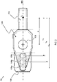
FIG 1 illustrates a first embodiment of abracket 10 for clamping an injector onto a cylinder head of an internal combustion engine; -
FIG 2 provides a bottom view of another or further embodiment of thebracket 10; -
FIG 3 provides a bottom view of yet another or further embodiment of thebracket 10; -
FIG 4 provides a schematic overview of amethod 20 of clamping an injector onto a cylinder head of an internal combustion engine by a bracket; -
FIGs 5A and 5B illustrate different results of themethod 20. - Aspects of the invention relate to a bracket for clamping an injector onto a cylinder head of an internal combustion engine. The bracket comprises a clamp section arranged for providing a clamping force onto the injector to clamp the injector onto the cylinder head, a mount section extending from the clamp section and arranged for mounting the bracket to the cylinder head adjacent the injector, and a support section extending from the mount section opposite the clamp section and arranged for supporting the bracket onto the cylinder head at a lever distance from the clamp section, to define the clamping force. The support section comprises a plurality of support elements, with each of the support elements arranged at a different lever distance, such that a selected support element from the plurality of support elements engages, in use, with the cylinder head at a selected lever distance, so that the bracket is supported on the selected support element only, to control a magnitude of the clamping force.
- In preferred embodiments, each support element of the plurality of support elements is arranged along a longitudinal axis extending between the support section and the clamp section, to simplify the design of bracket and to optimize the ratio of clamping capacity to weight of bracket.
- Additionally, in some embodiments the mount section can comprise a hole, having a centerline perpendicular to the longitudinal axis for accommodating a preload bolt, such that, in use, the preload bolt engages with the cylinder head, to provide a preload downward force for generating the clamping force.
- In yet further embodiments, the centerline intersects the longitudinal axis, to have the preload force provide a single lever action from a selected support element of the plurality of support elements to the clamp section.
- Preferably, each support element of the plurality of support elements comprises a convex semi sphere, to provide a well-defined contact surface for engaging with the cylinder head.
- In other or further preferred embodiments, each support element of the plurality of support elements is equal in size, to facilitate preparation of the cylinder head.
- In some embodiments, the clamp section comprises a plurality of branches, each branch of the plurality of branches arranged for providing at least part of the clamping force onto the injector, to distribute the clamping force onto the injector.
- The invention is described more fully hereinafter with reference to the accompanying drawings, in which embodiments of the invention are shown. In the drawings, the absolute and relative sizes of systems, components, layers, and regions may be exaggerated for clarity. Embodiments may be described with reference to schematic and/or cross-section illustrations of possibly idealized embodiments and intermediate structures of the invention. In the description and drawings, like numbers refer to like elements throughout. Relative terms as well as derivatives thereof should be construed to refer to the orientation as then described or as shown in the drawing under discussion. These relative terms are for convenience of description and do not require that the system be constructed or operated in a particular orientation unless stated otherwise.
- Now turning to
FIG 1 , there is illustrated abracket 10 for clamping aninjector 400 onto acylinder head 500 of an internal combustion engine according to a first embodiment.Bracket 10 comprises aclamp section 110, amount section 120, and asupport section 130.Clamp section 110 is arranged for providing a clamping force FC ontoinjector 400 toclamp injector 400 ontocylinder head 500.Mount section 120 extends fromclamp section 110 and is arranged for mountingbracket 10 tocylinder head 500adjacent injector 400, e.g. by a preload force Fp.Support section 130 extends frommount section 120opposite clamp section 110 and is arranged for supportingbracket 10 ontocylinder head 500 at a lever distance fromclamp section 110, to define the clamping force Fc. In the embodiment, the lever distance is thus determined by a distance between a clamping position, i.e. a central position where the clamping force is transmitted to theinjector 400, and a supporting position, i.e. a centerline of any of a supportingelement cylinder head 500. For example, a preload force Fp applied onmount section 120 when mountingbracket 10 tocylinder head 500 results, by lever action defined by lever distance LA,B, in a clamping force FC betweenclamp section 110 andinjector 400. As shown inFIG 1 ,support section 130 comprises a plurality ofsupport elements 135a,b. Each ofsupport elements 135a,b is arranged at a different lever distance LA,B fromclamp section 110. For example, the lever distance LA betweensupport element 135a andclamp section 110 is larger than the lever distance LB betweensupport element 135b andclamp section 110.FIG 1 shows thatselected support element 135a from the plurality ofsupport elements 135a,b engages, in use, withcylinder head 500 at selected lever distance LA, such thatbracket 10 is supported onselected support element 135a only. For example,cylinder head 500 may comprise a centering hole to align withselected support element 135a, while material is removed fromcylinder head 500 aroundnon-selected support element 135b, such thatbracket 10 is supported onselected support element 135a only. By having abracket 10 comprising a plurality of support elements at different lever distances fromclamp section 110, a selected support element can be arranged to engage, in use, with the cylinder head at a selected lever distance, to control a magnitude of the clamping force FC without changing the design or specification of the bracket and without changing the magnitude of the preload force Fp. For example, by selecting a different support element, such assupport element 135b instead ofsupport element 135a inFIG 1 , the magnitude of the clamping force FC can be reduced, due to the relatively shorter lever distance LB between selectedsupport element 135b andclamp section 110. Although not depicted inFIG 1 , the lever distance is typically dependent on the central mount section, typically a center bolt, which provides a downward clamping force Fp, which is transmitted, through the lever distance to a clamping force Fc. - In some embodiments, for example as shown in
FIG 1 , eachsupport element 135a,b of the plurality of support elements comprises a convex semi sphere, to provide a well-defined contact surface for engaging withcylinder head 500. A convex spherical contact surface can for example engage with a centering hole incylinder head 500, such thatbracket 10 is aligned and pivotably supported oncylinder head 500. Alternatively, each support element 135 of the plurality of support elements may comprise a different shape protruding fromsupport section 130, such as an end or a side of a cylinder, cone, or cuboid, such that each support element provides e.g. a flat, curved or double curved contact surface betweensupport section 110 andcylinder head 500. - Preferably, each
support element 135a,b of the plurality of support elements is equal in size, e.g. having an equal spherical diameter, or support width, or an equal length of protrusion fromsupport section 130, to facilitate preparation ofcylinder head 500, such thatbracket 10 is supported on a selected support element only. Alternatively, support elements of the plurality ofsupport elements 135a,b can have a different size relative to each other, e.g. differing in diameter, width, or length of protrusion fromsupport section 130, to match a surface ofcylinder head 500. -
FIG 2 provides a bottom view of another or further embodiment ofbracket 10. Eachsupport element 135a,b,c of the plurality of support elements is arranged along a singlelongitudinal axis 808 extending betweensupport section 130 andclamp section 110. As shown inFIG 2 ,support element 135a is arranged onlongitudinal axis 808 at lever distance LA fromclamp section 110,support element 135b is arranged onlongitudinal axis 808 at lever distance LB fromclamp section 110, andsupport element 135c is arranged onlongitudinal axis 808 at lever distance LC fromclamp section 110. Lever distances LA,B,C can be defined as the distance alonglongitudinal axis 808, from the location of clamp force FC onclamp section 110 to supportelements 135a,b, respectively. - By having each
support element 135a,b,c of the plurality of support elements arranged along a singlelongitudinal axis 808 extending betweensupport section 130 andclamp section 110, the design ofbracket 10 can be simplified and the ratio of clamping capacity to weight ofbracket 10 can be optimized. Preferably,longitudinal axis 808 is on a plane of symmetry ofbracket 10, to further simplify and optimize the design ofbracket 10. Alternatively,longitudinal axis 808 can be at an offset from the plane of symmetry ofbracket 10. - Additionally, in some embodiments mount
section 120 comprises acenter hole 125, having a centerline perpendicular tolongitudinal axis 808 for accommodating a preload center bolt, such that, in use, the preload bolt engages withcylinder head 500 to provide a preload downward force Fp for generating the clamping force Fc. The preload bolt can e.g. be used for mountingbracket 10 tocylinder head 500 and for providing the preload force Fp as shown inFIG 1 . - In preferred embodiments, the centerline of
hole 125 intersectslongitudinal axis 808, e.g. at a fixed distance R from the clamping force FC onclamp section 110, such that the preload force FP provides a single lever action from a selected support element of the plurality ofsupport elements 135a,b,c, to theclamp section 110, without providing a secondary, e.g. lateral, lever action onbracket 10. -
FIG 3 shows yet another or further embodiment of thebracket 10, in a bottom view. Here,clamp section 110 comprises a plurality of branches, e.g. twobranches branch injector 400. For example, the total clamping force FC can be divided between the plurality ofbranches branch 115 and a second part of the clamping force FC,2 onbranch 116. Alternatively,bracket 10 may for example comprise branches that do not contribute to providing a clamping force ontoinjector 400, but instead are designed e.g. for holding a cable or for alignment ofbracket 10,injector 400, or other components. - As shown in
FIG 3 , the clamping force FC,1, FC,2 onbranches longitudinal axis 808 extending betweensupport section 130 andclamp section 110. Accordingly, the lever distances LA,B can be defined as the distance alonglongitudinal axis 808, between a central clamping position on axis 909 andsupport elements 135a,b, respectively. - In
FIG 4 , a schematic overview is provided of amethod 20 of clamping aninjector 400 onto acylinder head 500 of an internal combustion engine by thebracket 10. Themethod 20 comprises, in afirst step 21, selecting a support element 135 at a selected lever distance, from a plurality of support elements 135 arranged for supporting thebracket 10 onto thecylinder head 500 at different lever distances from aclamp section 110 of thebracket 10, to control a magnitude of a clamping force. In asecond step 22, themethod 20 comprises modifying thecylinder head 500, such that the selected support element 135 from the plurality of support element 135 engages, in use, with thecylinder head 500 at the selected lever distance such that thebracket 10 is supported on the selected support element 135 only. - An example is given in
FIG 5A and 5B . InFIG 5A ,cylinder head 500 is modified such that selectedsupport element 135a from the plurality ofsupport elements 135a,b engages, in use, with a centering hole incylinder head 500 at the selected lever distance. Material around thenon-selected support element 135b is removed fromcylinder head 500, such thatbracket 10 is supported on selectedsupport element 135a only. Alternatively, inFIG 5B ,support element 135b is defined as the selected support element 135, andcylinder head 500 is modified such that selectedsupport element 135b engages in use with a centering hole incylinder head 500 at the corresponding selected lever distance, while material aroundnon-selected support element 135a is removed fromcylinder head 500, such thatbracket 10 is supported on selectedsupport element 135b only. - Back to
FIG 4 , in athird step 23 of themethod 20, thebracket 10 is mounted to thecylinder head 10 between the selected support element 135 and theinjector 400, to provide the clamping force onto theinjector 400 to clamp theinjector 400 onto thecylinder head 500. - In this way, the same bracket design and specification can be used on different engines and/or injectors spread over different projects, instead of requiring a new design and/or specification when a change of bracket would normally be required, thereby providing a cost advantage. Besides that, by modifying the cylinder head, the clamping force can be controlled with the same bracket in an easier, more cost efficient and less time consuming way, because of improved manufacturing, assembly, maintenance, and quality and inspection processes.
Claims (9)
- A bracket for clamping an injector onto a cylinder head of an internal combustion engine, comprising:- a clamp section, arranged for providing a clamping force onto the injector to clamp the injector onto the cylinder head;- a mount section, extending from the clamp section and arranged for mounting the bracket to the cylinder head adjacent the injector; and- a support section, extending from the mount section opposite the clamp section and arranged for supporting the bracket onto the cylinder head at a lever distance from the clamp section, to define the clamping force;
wherein the support section comprises a plurality of support elements, each of said support elements arranged at a different lever distance, such that a selected support element from the plurality of support elements engages, in use, with the cylinder head at a selected lever distance, such that the bracket is supported on the selected support element only, to control a magnitude of the clamping force. - Bracket according to claim 1, wherein each support element of the plurality of support elements is arranged along a longitudinal axis extending between the support section and the clamp section.
- Bracket according to claim 2, wherein the mount section comprises a hole, having a centerline perpendicular to the longitudinal axis for accommodating a preload bolt, such that, in use, the preload bolt engages with the cylinder head.
- Bracket according to claim 3, wherein the centerline intersects the longitudinal axis.
- Bracket according to any preceding claim, wherein each support element of the plurality of support elements comprises a convex semi sphere.
- Bracket according to any preceding claim, wherein each support element of the plurality of support elements is equal in size.
- Bracket according to any preceding claim, wherein the clamp section comprises a plurality of branches, each branch of the plurality of branches arranged for providing at least part of the clamping force onto the injector.
- A method of clamping an injector onto a cylinder head of an internal combustion engine by the bracket according to claim 1, comprising:- selecting, from a plurality of support elements arranged for supporting the bracket onto the cylinder head at different lever distances from a clamp section of the bracket, a support element at a selected lever distance to control a magnitude of a clamping force;- modifying the cylinder head, such that the selected support element from the plurality of support element engages, in use, with the cylinder head at the selected lever distance such that the bracket is supported on the selected support element only; and- mounting the bracket to the cylinder head between the selected support element and the injector, to provide the clamping force onto the injector to clamp the injector onto the cylinder head.
- A method according to claim 8, where the brackets are mounted to the cylinder head with a preload mounting force that is the same irrespective of a selected support element.
Applications Claiming Priority (1)
| Application Number | Priority Date | Filing Date | Title |
|---|---|---|---|
| NL2027770A NL2027770B1 (en) | 2021-03-18 | 2021-03-18 | Bracket and method for clamping an injector onto a cylinder head |
Publications (1)
| Publication Number | Publication Date |
|---|---|
| EP4060182A1 true EP4060182A1 (en) | 2022-09-21 |
Family
ID=76159929
Family Applications (1)
| Application Number | Title | Priority Date | Filing Date |
|---|---|---|---|
| EP22162610.4A Pending EP4060182A1 (en) | 2021-03-18 | 2022-03-17 | Bracket and method for clamping an injector onto a cylinder head |
Country Status (3)
| Country | Link |
|---|---|
| US (1) | US11473542B2 (en) |
| EP (1) | EP4060182A1 (en) |
| NL (1) | NL2027770B1 (en) |
Citations (6)
| Publication number | Priority date | Publication date | Assignee | Title |
|---|---|---|---|---|
| US6116218A (en) * | 1996-09-06 | 2000-09-12 | Nissan Motor Co., Ltd. | Fuel injector fixing device for direct injection engine |
| KR20020085007A (en) | 2001-05-04 | 2002-11-16 | 현대자동차주식회사 | Clamp apparatus of injector |
| US20100300408A1 (en) * | 2009-05-29 | 2010-12-02 | Cummins Intellectual Properties, Inc. | Fuel injector, clamping assembly and method of mounting a fuel injector |
| CN102562396A (en) | 2012-01-11 | 2012-07-11 | 清华大学 | Diesel engine oil injector hold-down device |
| DE102011088293A1 (en) * | 2011-12-12 | 2013-06-13 | Continental Automotive Gmbh | Clamping device e.g. clamp, for interlocking injector with cylinder head of internal combustion engine, has supporting section building force on injector by anchoring pin with base structure while metal part is connected with another part |
| DE202015103512U1 (en) * | 2014-07-22 | 2015-10-02 | Ford Global Technologies, Llc | Diesel fuel injectors terminal |
Family Cites Families (7)
| Publication number | Priority date | Publication date | Assignee | Title |
|---|---|---|---|---|
| DE2857679A1 (en) * | 1978-11-29 | 1980-12-04 | Caterpillar Tractor Co | INJECTION NOZZLE CLAMP |
| DE19629855C1 (en) * | 1996-07-24 | 1997-12-11 | Daimler Benz Ag | Device for fastening an injector holder |
| US6431152B1 (en) * | 2001-03-30 | 2002-08-13 | International Engine Intellectual Property Company, L.L.C. | Injector hold down clamp |
| DE10155678A1 (en) * | 2001-11-13 | 2003-05-22 | Bosch Gmbh Robert | Clamp, to lock a fuel injection valve in its drilling through the cylinder head of an IC motor, has a clamp paw which presses symmetrically against a linear bearing surface without a tilting movement |
| US6769409B2 (en) * | 2002-10-11 | 2004-08-03 | Caterpillar Inc | Fuel injector supporting device |
| JP4114601B2 (en) * | 2003-12-08 | 2008-07-09 | 日産自動車株式会社 | Fixed structure of fuel injection nozzle |
| EP1837517B1 (en) * | 2006-03-23 | 2008-12-03 | Delphi Technologies, Inc. | Injector mounting arrangement |
-
2021
- 2021-03-18 NL NL2027770A patent/NL2027770B1/en active
-
2022
- 2022-03-15 US US17/694,809 patent/US11473542B2/en active Active
- 2022-03-17 EP EP22162610.4A patent/EP4060182A1/en active Pending
Patent Citations (6)
| Publication number | Priority date | Publication date | Assignee | Title |
|---|---|---|---|---|
| US6116218A (en) * | 1996-09-06 | 2000-09-12 | Nissan Motor Co., Ltd. | Fuel injector fixing device for direct injection engine |
| KR20020085007A (en) | 2001-05-04 | 2002-11-16 | 현대자동차주식회사 | Clamp apparatus of injector |
| US20100300408A1 (en) * | 2009-05-29 | 2010-12-02 | Cummins Intellectual Properties, Inc. | Fuel injector, clamping assembly and method of mounting a fuel injector |
| DE102011088293A1 (en) * | 2011-12-12 | 2013-06-13 | Continental Automotive Gmbh | Clamping device e.g. clamp, for interlocking injector with cylinder head of internal combustion engine, has supporting section building force on injector by anchoring pin with base structure while metal part is connected with another part |
| CN102562396A (en) | 2012-01-11 | 2012-07-11 | 清华大学 | Diesel engine oil injector hold-down device |
| DE202015103512U1 (en) * | 2014-07-22 | 2015-10-02 | Ford Global Technologies, Llc | Diesel fuel injectors terminal |
Also Published As
| Publication number | Publication date |
|---|---|
| NL2027770B1 (en) | 2022-09-29 |
| US20220298998A1 (en) | 2022-09-22 |
| US11473542B2 (en) | 2022-10-18 |
Similar Documents
| Publication | Publication Date | Title |
|---|---|---|
| US6863053B2 (en) | Fuel injection apparatus for internal combustion engine | |
| US9321167B2 (en) | Pallet-based support system for vehicle engine and method | |
| US7699041B2 (en) | Fuel distribution tube for direct injection fuel rail assemblies | |
| US11274642B1 (en) | Fuel rail assembly | |
| US6769409B2 (en) | Fuel injector supporting device | |
| EP2098720B1 (en) | Fuel delivery system | |
| EP4060182A1 (en) | Bracket and method for clamping an injector onto a cylinder head | |
| US11208215B2 (en) | Method for mounting an aircraft pylon | |
| CN103764996B (en) | Fuel distributor bar | |
| KR100301383B1 (en) | Fuel injection device | |
| US6309131B1 (en) | Redundant clevis pin pair | |
| CN106414118A (en) | Component attachment with a transverse force-supporting surface | |
| US11434015B2 (en) | Aircraft engine attachment comprising at least one fork-type system for immobilizing a shear pin in translation, method for mounting said engine attachment and aircraft comprising said engine attachment | |
| US7412970B2 (en) | Cylinder head for a direct injection internal combustion engine | |
| CN105579697A (en) | Holder for fastening a fuel distributor to an internal combustion engine, and connecting method | |
| JP3274468B2 (en) | Solenoid valve assembly | |
| KR101072322B1 (en) | Pallet for engine assembling | |
| US8142152B2 (en) | Connection of radial arms to a circular sleeve via axes and spacers | |
| US20220034286A1 (en) | Injector clamping mechanism | |
| US4603617A (en) | Multi-part plunger piston for internal combustion engines | |
| KR20020044178A (en) | Clamping element for a fuel injection valve and fuel injection system | |
| CN110462746B (en) | Device for fastening cladding module to fusion reactor vacuum vessel | |
| EP1541863B1 (en) | Fixing structure for fuel injection nozzle | |
| KR102250931B1 (en) | Holder and arrangement having a fuel distributor and a plurality of holders | |
| US20220381273A1 (en) | Double eccentric type connection assembly comprising a ring made of deformable material for a connection between two structures of an aircraft, and aircraft comprising such an assembly |
Legal Events
| Date | Code | Title | Description |
|---|---|---|---|
| PUAI | Public reference made under article 153(3) epc to a published international application that has entered the european phase |
Free format text: ORIGINAL CODE: 0009012 |
|
| STAA | Information on the status of an ep patent application or granted ep patent |
Free format text: STATUS: THE APPLICATION HAS BEEN PUBLISHED |
|
| AK | Designated contracting states |
Kind code of ref document: A1 Designated state(s): AL AT BE BG CH CY CZ DE DK EE ES FI FR GB GR HR HU IE IS IT LI LT LU LV MC MK MT NL NO PL PT RO RS SE SI SK SM TR |
|
| STAA | Information on the status of an ep patent application or granted ep patent |
Free format text: STATUS: REQUEST FOR EXAMINATION WAS MADE |
|
| 17P | Request for examination filed |
Effective date: 20230316 |
|
| RBV | Designated contracting states (corrected) |
Designated state(s): AL AT BE BG CH CY CZ DE DK EE ES FI FR GB GR HR HU IE IS IT LI LT LU LV MC MK MT NL NO PL PT RO RS SE SI SK SM TR |
|
| P01 | Opt-out of the competence of the unified patent court (upc) registered |
Effective date: 20230505 |
|
| GRAP | Despatch of communication of intention to grant a patent |
Free format text: ORIGINAL CODE: EPIDOSNIGR1 |
|
| STAA | Information on the status of an ep patent application or granted ep patent |
Free format text: STATUS: GRANT OF PATENT IS INTENDED |
|
| RIC1 | Information provided on ipc code assigned before grant |
Ipc: F02M 61/14 20060101AFI20240223BHEP |
|
| INTG | Intention to grant announced |
Effective date: 20240326 |