EP4060167B1 - Abgasbehandlungsanordnung für eine abgasanlage einer brennkraftmaschine - Google Patents
Abgasbehandlungsanordnung für eine abgasanlage einer brennkraftmaschine Download PDFInfo
- Publication number
- EP4060167B1 EP4060167B1 EP22156011.3A EP22156011A EP4060167B1 EP 4060167 B1 EP4060167 B1 EP 4060167B1 EP 22156011 A EP22156011 A EP 22156011A EP 4060167 B1 EP4060167 B1 EP 4060167B1
- Authority
- EP
- European Patent Office
- Prior art keywords
- exhaust gas
- flow path
- arrangement
- liquid
- switching unit
- Prior art date
- Legal status (The legal status is an assumption and is not a legal conclusion. Google has not performed a legal analysis and makes no representation as to the accuracy of the status listed.)
- Active
Links
Images



Classifications
-
- F—MECHANICAL ENGINEERING; LIGHTING; HEATING; WEAPONS; BLASTING
- F01—MACHINES OR ENGINES IN GENERAL; ENGINE PLANTS IN GENERAL; STEAM ENGINES
- F01N—GAS-FLOW SILENCERS OR EXHAUST APPARATUS FOR MACHINES OR ENGINES IN GENERAL; GAS-FLOW SILENCERS OR EXHAUST APPARATUS FOR INTERNAL-COMBUSTION ENGINES
- F01N3/00—Exhaust or silencing apparatus having means for purifying, rendering innocuous, or otherwise treating exhaust
- F01N3/08—Exhaust or silencing apparatus having means for purifying, rendering innocuous, or otherwise treating exhaust for rendering innocuous
- F01N3/10—Exhaust or silencing apparatus having means for purifying, rendering innocuous, or otherwise treating exhaust for rendering innocuous by thermal or catalytic conversion of noxious components of exhaust
- F01N3/18—Exhaust or silencing apparatus having means for purifying, rendering innocuous, or otherwise treating exhaust for rendering innocuous by thermal or catalytic conversion of noxious components of exhaust characterised by methods of operation; Control
- F01N3/20—Exhaust or silencing apparatus having means for purifying, rendering innocuous, or otherwise treating exhaust for rendering innocuous by thermal or catalytic conversion of noxious components of exhaust characterised by methods of operation; Control specially adapted for catalytic conversion
- F01N3/206—Adding periodically or continuously substances to exhaust gases for promoting purification, e.g. catalytic material in liquid form, NOx reducing agents
- F01N3/2066—Selective catalytic reduction [SCR]
-
- F—MECHANICAL ENGINEERING; LIGHTING; HEATING; WEAPONS; BLASTING
- F01—MACHINES OR ENGINES IN GENERAL; ENGINE PLANTS IN GENERAL; STEAM ENGINES
- F01N—GAS-FLOW SILENCERS OR EXHAUST APPARATUS FOR MACHINES OR ENGINES IN GENERAL; GAS-FLOW SILENCERS OR EXHAUST APPARATUS FOR INTERNAL-COMBUSTION ENGINES
- F01N3/00—Exhaust or silencing apparatus having means for purifying, rendering innocuous, or otherwise treating exhaust
- F01N3/08—Exhaust or silencing apparatus having means for purifying, rendering innocuous, or otherwise treating exhaust for rendering innocuous
- F01N3/10—Exhaust or silencing apparatus having means for purifying, rendering innocuous, or otherwise treating exhaust for rendering innocuous by thermal or catalytic conversion of noxious components of exhaust
- F01N3/24—Exhaust or silencing apparatus having means for purifying, rendering innocuous, or otherwise treating exhaust for rendering innocuous by thermal or catalytic conversion of noxious components of exhaust characterised by constructional aspects of converting apparatus
- F01N3/28—Construction of catalytic reactors
-
- F—MECHANICAL ENGINEERING; LIGHTING; HEATING; WEAPONS; BLASTING
- F01—MACHINES OR ENGINES IN GENERAL; ENGINE PLANTS IN GENERAL; STEAM ENGINES
- F01N—GAS-FLOW SILENCERS OR EXHAUST APPARATUS FOR MACHINES OR ENGINES IN GENERAL; GAS-FLOW SILENCERS OR EXHAUST APPARATUS FOR INTERNAL-COMBUSTION ENGINES
- F01N3/00—Exhaust or silencing apparatus having means for purifying, rendering innocuous, or otherwise treating exhaust
- F01N3/005—Exhaust or silencing apparatus having means for purifying, rendering innocuous, or otherwise treating exhaust for draining or otherwise eliminating condensates or moisture accumulating in the apparatus
-
- F—MECHANICAL ENGINEERING; LIGHTING; HEATING; WEAPONS; BLASTING
- F01—MACHINES OR ENGINES IN GENERAL; ENGINE PLANTS IN GENERAL; STEAM ENGINES
- F01N—GAS-FLOW SILENCERS OR EXHAUST APPARATUS FOR MACHINES OR ENGINES IN GENERAL; GAS-FLOW SILENCERS OR EXHAUST APPARATUS FOR INTERNAL-COMBUSTION ENGINES
- F01N3/00—Exhaust or silencing apparatus having means for purifying, rendering innocuous, or otherwise treating exhaust
- F01N3/08—Exhaust or silencing apparatus having means for purifying, rendering innocuous, or otherwise treating exhaust for rendering innocuous
- F01N3/10—Exhaust or silencing apparatus having means for purifying, rendering innocuous, or otherwise treating exhaust for rendering innocuous by thermal or catalytic conversion of noxious components of exhaust
- F01N3/24—Exhaust or silencing apparatus having means for purifying, rendering innocuous, or otherwise treating exhaust for rendering innocuous by thermal or catalytic conversion of noxious components of exhaust characterised by constructional aspects of converting apparatus
- F01N3/28—Construction of catalytic reactors
- F01N3/2892—Exhaust flow directors or the like, e.g. upstream of catalytic device
-
- F—MECHANICAL ENGINEERING; LIGHTING; HEATING; WEAPONS; BLASTING
- F01—MACHINES OR ENGINES IN GENERAL; ENGINE PLANTS IN GENERAL; STEAM ENGINES
- F01N—GAS-FLOW SILENCERS OR EXHAUST APPARATUS FOR MACHINES OR ENGINES IN GENERAL; GAS-FLOW SILENCERS OR EXHAUST APPARATUS FOR INTERNAL-COMBUSTION ENGINES
- F01N2240/00—Combination or association of two or more different exhaust treating devices, or of at least one such device with an auxiliary device, not covered by indexing codes F01N2230/00 or F01N2250/00, one of the devices being
- F01N2240/20—Combination or association of two or more different exhaust treating devices, or of at least one such device with an auxiliary device, not covered by indexing codes F01N2230/00 or F01N2250/00, one of the devices being a flow director or deflector
-
- F—MECHANICAL ENGINEERING; LIGHTING; HEATING; WEAPONS; BLASTING
- F01—MACHINES OR ENGINES IN GENERAL; ENGINE PLANTS IN GENERAL; STEAM ENGINES
- F01N—GAS-FLOW SILENCERS OR EXHAUST APPARATUS FOR MACHINES OR ENGINES IN GENERAL; GAS-FLOW SILENCERS OR EXHAUST APPARATUS FOR INTERNAL-COMBUSTION ENGINES
- F01N2410/00—By-passing, at least partially, exhaust from inlet to outlet of apparatus, to atmosphere or to other device
-
- F—MECHANICAL ENGINEERING; LIGHTING; HEATING; WEAPONS; BLASTING
- F01—MACHINES OR ENGINES IN GENERAL; ENGINE PLANTS IN GENERAL; STEAM ENGINES
- F01N—GAS-FLOW SILENCERS OR EXHAUST APPARATUS FOR MACHINES OR ENGINES IN GENERAL; GAS-FLOW SILENCERS OR EXHAUST APPARATUS FOR INTERNAL-COMBUSTION ENGINES
- F01N2570/00—Exhaust treating apparatus eliminating, absorbing or adsorbing specific elements or compounds
- F01N2570/12—Hydrocarbons
-
- F—MECHANICAL ENGINEERING; LIGHTING; HEATING; WEAPONS; BLASTING
- F01—MACHINES OR ENGINES IN GENERAL; ENGINE PLANTS IN GENERAL; STEAM ENGINES
- F01N—GAS-FLOW SILENCERS OR EXHAUST APPARATUS FOR MACHINES OR ENGINES IN GENERAL; GAS-FLOW SILENCERS OR EXHAUST APPARATUS FOR INTERNAL-COMBUSTION ENGINES
- F01N2570/00—Exhaust treating apparatus eliminating, absorbing or adsorbing specific elements or compounds
- F01N2570/22—Water or humidity
-
- F—MECHANICAL ENGINEERING; LIGHTING; HEATING; WEAPONS; BLASTING
- F01—MACHINES OR ENGINES IN GENERAL; ENGINE PLANTS IN GENERAL; STEAM ENGINES
- F01N—GAS-FLOW SILENCERS OR EXHAUST APPARATUS FOR MACHINES OR ENGINES IN GENERAL; GAS-FLOW SILENCERS OR EXHAUST APPARATUS FOR INTERNAL-COMBUSTION ENGINES
- F01N2610/00—Adding substances to exhaust gases
- F01N2610/02—Adding substances to exhaust gases the substance being ammonia or urea
-
- Y—GENERAL TAGGING OF NEW TECHNOLOGICAL DEVELOPMENTS; GENERAL TAGGING OF CROSS-SECTIONAL TECHNOLOGIES SPANNING OVER SEVERAL SECTIONS OF THE IPC; TECHNICAL SUBJECTS COVERED BY FORMER USPC CROSS-REFERENCE ART COLLECTIONS [XRACs] AND DIGESTS
- Y02—TECHNOLOGIES OR APPLICATIONS FOR MITIGATION OR ADAPTATION AGAINST CLIMATE CHANGE
- Y02A—TECHNOLOGIES FOR ADAPTATION TO CLIMATE CHANGE
- Y02A50/00—TECHNOLOGIES FOR ADAPTATION TO CLIMATE CHANGE in human health protection, e.g. against extreme weather
- Y02A50/20—Air quality improvement or preservation, e.g. vehicle emission control or emission reduction by using catalytic converters
-
- Y—GENERAL TAGGING OF NEW TECHNOLOGICAL DEVELOPMENTS; GENERAL TAGGING OF CROSS-SECTIONAL TECHNOLOGIES SPANNING OVER SEVERAL SECTIONS OF THE IPC; TECHNICAL SUBJECTS COVERED BY FORMER USPC CROSS-REFERENCE ART COLLECTIONS [XRACs] AND DIGESTS
- Y02—TECHNOLOGIES OR APPLICATIONS FOR MITIGATION OR ADAPTATION AGAINST CLIMATE CHANGE
- Y02T—CLIMATE CHANGE MITIGATION TECHNOLOGIES RELATED TO TRANSPORTATION
- Y02T10/00—Road transport of goods or passengers
- Y02T10/10—Internal combustion engine [ICE] based vehicles
- Y02T10/12—Improving ICE efficiencies
Definitions
- the present invention relates to an exhaust gas treatment arrangement which can be used in an exhaust system of an internal combustion engine, in particular in a vehicle, to subject the exhaust gas emitted by an internal combustion engine to an exhaust gas purification process.
- the exhaust gas treatment arrangement constructed according to the invention it is fundamentally possible, depending on the operating state of an internal combustion engine or an exhaust system, to direct a more or less large part of the exhaust gas flow through the first exhaust gas flow path and thus through the SCR catalytic converter arrangement, or through the second exhaust gas flow path which is fluidly parallel to the first exhaust gas flow path To guide the exhaust gas flow path and thus bypass the SCR catalytic converter arrangement.
- the operating state of an internal combustion engine or an injector arranged upstream of such an exhaust gas treatment arrangement with which liquid hydrocarbon, i.e.
- the structure according to the invention ensures that liquid, for example liquid hydrocarbon carried in the exhaust gas stream, is separated from the exhaust gas stream in the liquid collection area and can collect there and then over the liquid bypass line to be introduced further downstream into the second exhaust gas flow path.
- liquid, i.e. unburned, hydrocarbon from entering the first exhaust gas flow path and thus the SCR catalytic converter arrangement.
- the hydrocarbon can be used further downstream, in particular downstream of the SCR catalyst arrangement, for example in a particle filter to increase the temperature, for example to burn off soot particles deposited on the particle filter.
- the liquid collection region in the exhaust gas duct can comprise a liquid collection volume that is open in the upstream direction and substantially closed in the downstream direction and a liquid discharge opening that is open to the liquid bypass line, wherein the liquid collection volume preferably surrounds an exhaust gas flow volume in the exhaust gas duct in a ring-like manner in order to avoid impairment of the exhaust gas flow.
- the liquid collection volume can be formed between a wall of a first exhaust duct element of the exhaust duct and a wall of a second exhaust duct element.
- the second exhaust duct element can be inserted into the first exhaust duct element, for example into a downstream end of the first exhaust duct element, and the liquid collecting volume can be between a section of the wall of the second exhaust duct element extending in the first exhaust duct element and a section of the wall surrounding the second exhaust duct element be formed first exhaust duct element.
- the SCR catalyst arrangement is arranged in a housing that provides the exhaust gas outlet or leads to the exhaust gas outlet and that an outlet opening of the SCR catalyst arrangement is open to the exhaust gas outlet, and that the second exhaust gas flow path comprises an internal volume of the housing that accommodates the SCR catalyst arrangement and leads to the exhaust gas outlet.
- the SCR catalyst arrangement is thus located in a volume through which exhaust gas flowing in the second exhaust gas flow path flows, so that this exhaust gas flow can be used to transfer heat to the SCR catalyst arrangement and also to heat it from the outside or to keep it at a temperature required to carry out a catalytic reaction.
- the liquid discharge area can, for example, be open to the internal volume of the housing.
- the first exhaust gas flow path can comprise a first exhaust gas guide arrangement for directing exhaust gas from the flow path switching unit to a first exhaust gas inlet of the housing, wherein an inlet opening of the SCR catalytic converter arrangement is open to and/or provides the first exhaust gas inlet of the housing, and the second exhaust flow path may include a second exhaust guide assembly for directing exhaust from the flow path switching unit to a second exhaust inlet of the housing open to the interior volume of the housing.
- liquid delivery area is arranged on the housing adjacent to the second exhaust gas inlet, a Venturi effect is generated by the exhaust gas flow in the second exhaust gas flow path upon entry into the inner volume of the housing, which supports the delivery of liquid passed through the liquid bypass line into the inner volume of the housing
- the flow path switching unit can comprise an adjusting flap arrangement.
- the invention further relates to an exhaust system for an internal combustion engine, comprising an exhaust treatment arrangement constructed according to the invention.
- At least one exhaust gas treatment system can be arranged downstream of the exhaust gas outlet.
- At least one exhaust gas treatment system can include an oxidation catalytic converter and/or a particle filter. Furthermore, at least one exhaust gas treatment system can comprise a further SCR catalyst arrangement, so that the SCR catalyst arrangement provided in the exhaust gas treatment arrangement constructed according to the invention provides a pre-SCR catalyst.
- the liquid bypass line leads away from a lower region of the liquid collection volume in a height direction, and/or that the liquid discharge region is arranged in the height direction below the liquid collection volume.
- the height direction in an earth coordinate system essentially corresponds to a vertical direction, i.e. a direction of gravity.
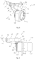
- the Fig. 1 to 5 show in various perspective views an exhaust gas treatment arrangement 10 for an exhaust system of an internal combustion engine.
- the exhaust gas treatment arrangement 10 comprises, as an upstream system region, an exhaust gas duct generally designated 12 through which the exhaust gas flow A emitted by an internal combustion engine flows.
- the exhaust gas duct 12 leads to a flow path switching unit 14 designed or operating in the manner of a flow switch.
- a branching takes place into a first exhaust gas flow path 16 and a second exhaust gas flow path 18 which is fluidically parallel to the first exhaust gas flow path 16, i.e. not necessarily geometrically parallel.
- the first exhaust gas flow path 16 comprises a first exhaust gas guide arrangement, generally designated 20, with a pipe-like line section 22 leading away from the flow path switching unit 14 and a housing-like line section 24 adjoining the line section 22.
- the line section 24 leads to a first exhaust gas inlet 26 of, for example box-shaped housing 28.
- An SCR catalyst arrangement is arranged in the housing 28, which is shown open.
- This comprises a tubular casing 34, in which an exhaust gas treatment element 38, which is constructed and/or coated with catalytically active material and is porous and through which exhaust gas can flow, is supported, for example by a fiber mat 36 or the like.
- An inlet opening 40 of the SCR catalyst arrangement 32 is open to the first exhaust gas inlet 26 of the housing 28 or provides this, so that exhaust gas guided through the line section 24 or the first exhaust gas flow path 20 flows into the inlet opening 40 of the SCR catalyst arrangement 32 and thus flows through the exhaust gas treatment element 38 thereof.
- An outlet opening 42 of the SCR catalyst arrangement 32 is located opposite an exhaust gas outlet 44 provided on the housing 28, so that exhaust gas flowing through the SCR catalyst arrangement 32 after exiting the Outlet opening 42 flows in the direction of the exhaust outlet 44 and via the outlet 44 the exhaust gas treatment arrangement 10 flows, for example, to further exhaust gas treatment systems 46, 48 of an exhaust system of an internal combustion engine, generally designated 50 and also comprising the exhaust gas treatment arrangement 10.
- These further exhaust gas treatment systems 46, 48 can, for example, comprise an oxidation catalyst, in particular a diesel oxidation catalyst, a particle filter, in particular a diesel particle filter, and a further SCR catalyst arrangement, so that the SCR catalyst arrangement 32 arranged in the housing 28 provides a pre-SCR catalyst.
- the reactant required to carry out a selective catalytic reduction in the SCR catalyst arrangement 32 for example a urea/water solution, can be injected in the area of an injection region 52 in the line section 22 by means of an injector, not shown in the figures, and while flowing through the first exhaust gas flow path 16 mix with the exhaust gas before being introduced into the SCR catalytic converter arrangement 32.
- the second exhaust gas flow path 18 comprises, adjacent to the flow path switching unit 14, a second exhaust gas guide arrangement 54, designed for example in the form of a pipe or in the manner of a manifold. This guides the exhaust gas flow flowing in the second exhaust gas flow path 18 towards a second exhaust gas inlet 56 of the housing 28. Via This second inlet 56, the exhaust gas guide arrangement 54 is open to the internal volume 30 of the housing 28, so that this internal volume 30 provides a part of the second exhaust gas flow path 18 leading to the exhaust gas outlet 44.
- the exhaust gas flowing through the inner volume 30 in the second exhaust gas flow path 18 flows around the outside of the SCR catalytic converter arrangement 32 and can therefore transfer heat to it.
- the exhaust gas stream flowing through the second exhaust gas flow path 18 does not enter the SCR catalytic converter arrangement 32 in the area of the outlet opening 42, since the exhaust gas stream flowing through the internal volume 30, as indicated by flow arrows, directly to the exhaust gas outlet 44 and the following one due to the significantly lower flow resistance Part of the exhaust system 50 flows.
- the flow path switching unit 14 can have an in Fig. 6 include the control flap arrangement 58 shown in principle.
- the control flap arrangement 58 can, for example, be designed so that it can be switched between two control states. In one of the setting states, the second exhaust gas flow path 18 is blocked against flow and the first exhaust gas flow path 16 is opened for flow. In the second positioning state, the first exhaust gas flow path 16 is shut off and the second exhaust gas flow path 18 is released for flow.
- the control flap arrangement 58 can be designed in the manner of a throttle valve used in exhaust systems, which can be arranged, for example, in the area of the flow path switching unit 14 leading to the second exhaust gas flow path 18.
- the second exhaust gas flow path 18 can be opened for flow in a first positioning state, while in a second positioning state the second exhaust gas flow path 18 is essentially blocked against flow. Since the first exhaust gas flow path 16 provides a significantly higher flow resistance for the exhaust gas due to the provision of the SCR catalytic converter arrangement 32 in the first exhaust gas flow path 16, when the second exhaust gas flow path 18 is open for flow, the exhaust gas flow A brought in via the exhaust gas duct 12 is essentially completely passed through the second exhaust gas flow path 18 stream.
- the control flap arrangement 58 can be brought into an intermediate position in which it does not completely block or completely open either of the two exhaust gas flow paths 16, 18, so that, for example, in order to efficiently heat the exhaust gas treatment element 38 of the SCR catalyst arrangement 32, a portion of the exhaust gas flow A is passed through the exhaust gas treatment element 38 via the first exhaust gas flow path 18 and the remaining portion of the exhaust gas flow A flows into the inner volume 30 of the housing 28 via the second exhaust gas flow path 18, thereby transferring heat from the outside to the SCR catalyst arrangement 32 by flowing around the casing 34 of the latter.
- the exhaust gas treatment arrangement 10 further comprises a liquid bypass line 60, which is designed, for example, as a tube. This leads from a liquid collecting area 62 formed on the exhaust gas duct 12 to a liquid delivery area 64 formed on the housing 28.
- the in Fig. 7 The liquid collecting area shown in more detail includes in the exhaust gas channel 12 a liquid collecting volume 68 which surrounds an exhaust gas flow volume 66 in the exhaust gas channel 12 in a ring-like manner. This is open in the upstream direction and is essentially closed in the downstream direction.
- the exhaust duct 12 comprises a first exhaust duct element 70 and a second exhaust duct element 74, for example a pipe-like one, inserted into a downstream end 72 of the first exhaust duct element 70.
- a section 76 of a wall 78 of the second exhaust duct element 74 extends in the upstream direction into the first exhaust duct element 70 in and is surrounded by a ring-like bulge area 80 of a wall 82 of the first exhaust duct element 70.
- the liquid bypass line 60 is connected to a connecting piece 84 on the wall 82 of the first exhaust channel element 70. In the area of this connecting piece 84, a liquid drainage opening 86 is formed, via which the liquid collecting volume 68 is open to the liquid bypass line 60.
- the liquid bypass line 60 leads to the housing 28 or a connector 88 arranged thereon adjacent to the second exhaust gas inlet 56, via which the liquid bypass line 60 is connected to the housing 28 and the liquid delivery area 64 is open to the internal volume 30 immediately adjacent to the second exhaust gas inlet 56.
- the liquid discharge opening 86 is provided on the liquid collection volume 68 in a lower area in a height direction, i.e. a direction of gravity, so that under the influence of gravity, liquid accumulating in the liquid collection volume 68 flows to the liquid discharge opening 86 and through this into the liquid bypass line 60. Furthermore, the liquid discharge region 64 is arranged in this height direction below the liquid collection volume 68, so that under the influence of gravity, the liquid leaving the liquid collection volume 68 is guided to the liquid discharge region 64 and via this into the second exhaust gas flow path.
- the exhaust gas stream A may contain unburned liquid hydrocarbon carried in droplet form.
- This can or should be used, for example, in one of the exhaust gas treatment systems 46 or 48 in order to increase the temperature there through oxidation, i.e. combustion.
- this can be used in a particle filter to burn off soot particles that have precipitated there.
- the liquid bypass line 60 bridges the flow path switching unit 14, so that regardless of the positioning state it is in, the liquid is separated from the exhaust gas stream A in the liquid collection area 62 and there collected liquid hydrocarbon is directed downstream of the flow path switching unit 14 into the second exhaust gas flow path 18 and thus, like the entire second exhaust gas flow path 18, is directed parallel to the first exhaust gas flow path 16 containing the SCR catalyst arrangement 32.
- the risk of liquid hydrocarbon entering the SCR catalytic converter arrangement 32 can therefore be largely eliminated.
- liquid hydrocarbon accumulating in the area of the liquid collection area 62 can be used further downstream, in particular also downstream of the SCR catalytic converter arrangement 32, in the manner described above in subsequent exhaust gas treatment systems 46 and 48.
Landscapes
- Engineering & Computer Science (AREA)
- Chemical & Material Sciences (AREA)
- Chemical Kinetics & Catalysis (AREA)
- Combustion & Propulsion (AREA)
- Mechanical Engineering (AREA)
- General Engineering & Computer Science (AREA)
- Health & Medical Sciences (AREA)
- Toxicology (AREA)
- Exhaust Gas After Treatment (AREA)
Description
- Die vorliegende Erfindung betrifft eine Abgasbehandlungsanordnung, welche in einer Abgasanlage einer Brennkraftmaschine, insbesondere in einem Fahrzeug, dazu genutzt werden kann, das von einer Brennkraftmaschine ausgestoßene Abgas einem Abgasreinigungsprozess zu unterziehen.
- Zur Verringerung des Schadstoffanteils in dem von einer Brennkraftmaschine ausgestoßenen Abgas ist es bekannt, verschiedene Abgasbehandlungseinheiten, wie zum Beispiel Katalysatoren und Partikelfilter, einzusetzen. Beispielsweise ist es Verbindung mit Diesel-Brennkraftmaschinen bekannt, zum Verringern des Stickoxidanteils im Abgas SCR-Katalysatoren einzusetzen, wie in
US2014250865A1 offenbart. - Es ist die Aufgabe der vorliegenden Erfindung, eine Abgasbehandlungsanordnung für eine Abgasanlage einer Brennkraftmaschine vorzusehen, welche eine Beeinträchtigung der Funktionalität eines im Abgasströmungsweg angeordneten SCR-Katalysators durch im Abgasstrom mitgeführte Kohlenwasserstoffpartikel vermeidet.
- Erfindungsgemäß wird diese Aufgabe gelöst durch eine Abgasbehandlungsanordnung für eine Abgasanlage einer Brennkraftmaschine gemäß Anspruch 1. Diese Abgasbehandlungsanordnung umfasst:
- einen zu einer Strömungsweg-Umschalteinheit führenden Abgaskanal, wobei die Strömungsweg-Umschalteinheit zum Verändern von in einen ersten Abgasströmungsweg stromabwärts der Strömungsweg-Umschalteinheit und einen zweiten Abgasströmungsweg stromabwärts der Strömungsweg-Umschalteinheit geleiteten Abgasstromanteilen eines den Abgaskanal durchströmenden Abgasstroms ausgebildet ist, wobei der erste Abgasströmungsweg und der zweite Abgasströmungsweg zu einem Abgasauslass führen,
- eine SCR-Katalysatoranordnung im ersten Abgasströmungsweg stromaufwärts des Abgasauslasses,
- eine Flüssigkeitsbypassleitung zum Ableiten von Flüssigkeit aus einem Flüssigkeitssammelbereich im Abgaskanal stromaufwärts bezüglich der Strömungsweg-Umschalteinheit zu einem Flüssigkeitsabgabebereich zur Abgabe von Flüssigkeit in den zweiten Abgasströmungsweg stromabwärts der Strömungsweg-Umschalteinheit.
- Bei der erfindungsgemäß aufgebauten Abgasbehandlungsanordnung besteht grundsätzlich die Möglichkeit, abhängig vom Betriebszustand einer Brennkraftmaschine bzw. einer Abgasanlage einen mehr oder weniger großen Teil des Abgasstroms durch den ersten Abgasströmungsweg und somit durch die SCR-Katalysatoranordnung zu leiten, oder durch den strömungstechnisch zum ersten Abgasströmungsweg parallelen zweiten Abgasströmungsweg zu leiten und somit die SCR-Katalysatoranordnung zu umgehen. Abhängig vom Betriebszustand einer Brennkraftmaschine oder eines stromaufwärts einer derartigen Abgasbehandlungsanordnung angeordneten Injektors, mit welchem flüssiger Kohlenwasserstoff, also Kraftstoff, in den Abgasstrom eingeleitet werden kann, beispielsweise um in einem einen Partikelfilter umfassenden Abgasbehandlungssystem eine Reinigung des Partikelfilters durchzuführen, enthält der Abgasstrom einen mehr oder weniger großen Anteil von in Tröpfchenform mitgeführtem, flüssigem Kohlenwasserstoff. Da derartiger flüssiger Kohlenwasserstoff die Funktionalität des Katalysatormaterials einer SCR-Katalysatoranordnung beeinträchtigen kann, wird mit dem erfindungsgemäßen Aufbau dafür gesorgt, dass Flüssigkeit, also beispielsweise im Abgasstrom mitgeführter flüssiger Kohlenwasserstoff, im Flüssigkeitssammelbereich aus dem Abgasstrom ausgeschieden wird und sich dort sammeln kann, um dann über die Flüssigkeitsbypassleitung weiter stromabwärts in den zweiten Abgasströmungsweg eingeleitet zu werden. Es wird somit ein Eintreten von flüssigem, also unverbranntem Kohlenwasserstoff in den ersten Abgasströmungsweg und somit die SCR-Katalysatoranordnung weitestgehend vermieden. Gleichwohl kann der Kohlenwasserstoff weiter stromabwärts, insbesondere stromabwärts der SCR-Katalysatoranordnung, beispielsweise in einem Partikelfilter zur Temperaturerhöhung beispielsweise zum Abbrennen von am Partikelfilter niedergeschlagenen Rußpartikeln genutzt werden.
- Für ein effizientes Abscheiden von Flüssigkeit aus dem Abgasstrom kann der Flüssigkeitssammelbereich im Abgaskanal ein in Richtung stromaufwärts offenes und in Richtung stromabwärts im Wesentlichen abgeschlossenes Flüssigkeitssammelvolumen und eine zu der Flüssigkeitsbypassleitung offene Flüssigkeitsableitöffnung umfassen, wobei zum Vermeiden einer Beeinträchtigung der Abgasströmung vorzugsweise das Flüssigkeitssammelvolumen ein Abgasströmungsvolumen im Abgaskanal ringartig umgibt.
- Das Flüssigkeitssammelvolumen kann zwischen einer Wand eines ersten Abgaskanalelements des Abgaskanals und einer Wand eines zweiten Abgaskanalelements gebildet sein. Hierzu kann das zweite Abgaskanalelement in das erste Abgaskanalelement, beispielsweise in ein stromabwärtiges Ende des ersten Abgaskanalelements, eingesetzt sein, und das Flüssigkeitssammelvolumen kann zwischen einem in dem ersten Abgaskanalelement sich erstreckenden Abschnitt der Wand des zweiten Abgaskanalelements und einem das zweite Abgaskanalelement umgebenden Abschnitt der Wand des ersten Abgaskanalelements gebildet sein.
- Bei einer besonders vorteilhaften Ausgestaltung wird vorgeschlagen, dass die SCR-Katalysatoranordnung in einem den Abgasauslass bereitstellenden oder zu dem Abgasauslass führenden Gehäuse angeordnet ist und eine Auslassöffnung der SCR-Katalysatoranordnung zu dem Abgasauslass offen ist, und dass der zweite Abgasströmungsweg ein die SCR-Katalysatoranordnung aufnehmendes und zu dem Abgasauslass führendes Innenvolumen des Gehäuses umfasst. Die SCR-Katalysatoranordnung liegt somit in einem Volumen, welches von im zweiten Abgasströmungsweg strömendem Abgas durchströmt wird, so dass dieser Abgasstrom dazu genutzt werden kann, Wärme auf die SCR-Katalysatoranordnung zu übertragen und diese auch von außen zu erwärmen bzw. auf einer für die Durchführung einer katalytischen Reaktion erforderlichen Temperatur zu halten.
- Der Flüssigkeitsabgabebereich kann beispielsweise zu dem Innenvolumen des Gehäuses offen sein.
- Zum Einrichten der verschiedenen Abgasströmungswege kann der erste Abgasströmungsweg eine erste Abgasleitanordnung zum Leiten von Abgas von der Strömungsweg-Umschalteinheit zu einem ersten Abgaseinlass des Gehäuses umfassen, wobei eine Einlassöffnung der SCR-Katalysatoranordnung zu dem ersten Abgaseinlass des Gehäuses offen ist oder/und diesen bereitstellt, und der zweite Abgasströmungsweg kann eine zweite Abgasleitanordnung zum Leiten von Abgas von der Strömungsweg-Umschalteinheit zu einem zu dem Innenvolumen des Gehäuses offenen zweiten Abgaseinlass des Gehäuses umfassen.
- Wenn dabei der Flüssigkeitsabgabebereich an dem Gehäuse benachbart zu dem zweiten Abgaseinlass angeordnet ist, wird durch den Abgasstrom im zweiten Abgasströmungsweg beim Eintritt in das Innenvolumen des Gehäuses ein Venturieffekt erzeugt, welcher die Abgabe von durch die Flüssigkeitsbypassleitung geleiteter Flüssigkeit in das Innenvolumen des Gehäuses unterstützt
- Bei einem einfach zu realisierenden Aufbau kann die Strömungsweg-Umschalteinheit eine Stellklappenanordnung umfassen.
- Die Erfindung betrifft ferner eine Abgasanlage für einen Brennkraftmaschine, umfassend eine erfindungsgemäß aufgebaute Abgasbehandlungsanordnung.
- Um in einer derartigen Abgasanlage eine weiter verbesserte Reinigungswirkung für das diese durchströmende Abgas bereitstellen zu können, kann stromabwärts des Abgasauslasses wenigstens ein Abgasbehandlungssystem angeordnet sein.
- Dabei kann wenigstens ein Abgasbehandlungssystem einen Oxidationskatalysator oder/und einen Partikelfilter umfassen. Weiter kann wenigstens ein Abgasbehandlungssystem eine weitere SCR-Katalysatoranordnung umfassen, so dass die in der erfindungsgemäß aufgebauten Abgasbehandlungsanordnung vorgesehene SCR-Katalysatoranordnung einen Vor-SCR-Katalysator bereitstellt.
- Um bei einer Abgasanlage die Schwerkraft zum Ableiten von Flüssigkeit aus dem Flüssigkeitssammelvolumen nutzen zu können, wird weiter vorgeschlagen, dass die Flüssigkeitsbypassleitung von einem in einer Höhenrichtung unteren Bereich des Flüssigkeitssammelvolumens weg führt, oder/und dass der Flüssigkeitsabgabebereich in der Höhenrichtung unter dem Flüssigkeitssammelvolumen angeordnet ist. Es ist in diesem Zusammenhang darauf hinzuweisen, dass die Höhenrichtung in einem Erdkoordinatensystem im Wesentlichen einer Vertikalrichtung, also einer Schwerkraftrichtung, entspricht.
- Die vorliegende Erfindung wird nachfolgend mit Bezug auf die beiliegenden Figuren detailliert beschrieben. Es zeigt:
- Fig. 1
- eine perspektivische Ansicht einer Abgasbehandlungsanordnung mit zwei parallelen Abgasströmungswegen in Blickrichtung I in
Fig. 2 ; - Fig. 2
- eine andere perspektivische Ansicht der Abgasbehandlungsanordnung in Blickrichtung II in
Fig. 1 ; - Fig. 3
- eine weitere perspektivische Ansicht der Abgasbehandlungsanordnung in Blickrichtung III in
Fig. 2 ; - Fig. 4
- eine Seitenansicht der Abgasbehandlungsanordnung in Blickrichtung IV in
Fig. 3 ; - Fig. 5
- die Abgasbehandlungsanordnung mit aufgeschnitten dargestelltem Gehäuse;
- Fig. 6
- einen aufgeschnitten dargestellten Abgaskanal der Abgasbehandlungsanordnung;
- Fig. 7
- einen vergrößert dargestellten Ausschnitt der
Fig. 6 im Bereich eines Flüssigkeitssammelbereichs. - Die
Fig. 1 bis 5 zeigen in verschiedenen perspektivischen Darstellungen eine Abgasbehandlungsanordnung 10 für eine Abgasanlage einer Brennkraftmaschine. Die Abgasbehandlungsanordnung 10 umfasst als stromaufwärtigen Systembereich einen allgemein mit 12 bezeichneten Abgaskanal, durch welchen der von einer Brennkraftmaschine ausgestoßene Abgasstrom A strömt. Der Abgaskanal 12 führt zu einer nach Art einer Strömungsweiche ausgebildeten bzw. arbeitenden Strömungsweg-Umschalteinheit 14. An der Strömungsweg-Umschalteinheit 14 findet eine Aufzweigung in einen ersten Abgasströmungsweg 16 und einen zum ersten Abgasströmungsweg 16 strömungstechnisch, also nicht notwendigerweise in geometrischer Hinsicht parallelen zweiten Abgasströmungsweg 18 statt. - Der erste Abgasströmungsweg 16 umfasst eine allgemein mit 20 bezeichnete erste Abgasleitanordnung mit einem von der Strömungsweg-Umschalteinheit 14 weg führenden, rohrartigen Leitungsabschnitt 22 und einem an den Leitungsabschnitt 22 anschließenden, gehäuseartig ausgebildeten Leitungsabschnitt 24. Der Leitungsabschnitt 24 führt zu einem ersten Abgaseinlass 26 eines beispielsweise kastenartig ausgebildeten Gehäuses 28.
- In einem Innenvolumen 30 des in
Fig. 5 offen dargestellten Gehäuses 28 ist eine allgemein mit 32 bezeichnete SCR-Katalysatoranordnung angeordnet. Diese umfasst einen rohrartigen Mantel 34, in welchem beispielsweise durch eine Fasermatte 36 oder dergleichen ein mit katalytisch wirksamem Material aufgebautes oder/und beschichtetes, poröses und somit von Abgas durchströmbares Abgasbehandlungselement 38 getragen ist. Eine Einlassöffnung 40 der SCR-Katalysatoranordnung 32 ist zum ersten Abgaseinlass 26 des Gehäuses 28 offen bzw. stellt diesen bereit, so dass durch den Leitungsabschnitt 24 bzw. den ersten Abgasströmungsweg 20 geleitetes Abgas in die Einlassöffnung 40 der SCR-Katalysatoranordnung 32 einströmt und somit das Abgasbehandlungselement 38 derselben durchströmt. - Eine Auslassöffnung 42 der SCR-Katalysatoranordnung 32 liegt einem am Gehäuse 28 vorgesehenen Abgasauslass 44 gegenüber, so dass die SCR-Katalysatoranordnung 32 durchströmendes Abgas nach dem Austritt aus der Auslassöffnung 42 in Richtung zum Abgasauslass 44 strömt und über den Auslass 44 die Abgasbehandlungsanordnung 10 beispielsweise zu weiteren Abgasbehandlungssystemen 46, 48 einer allgemein mit 50 bezeichneten und auch die Abgasbehandlungsanordnung 10 umfassenden Abgasanlage einer Brennkraftmaschine strömt. Diese weiteren Abgasbehandlungssysteme 46, 48 können beispielsweise einen Oxidationskatalysator, insbesondere Diese-Oxidationskatalysator, einen Partikelfilter, insbesondere Diesel-Partikelfilter, und eine weitere SCR-Katalysatoranordnung umfassen, so dass die im Gehäuse 28 angeordnete SCR-Katalysatoranordnung 32 einen Vor-SCR-Katalysator bereitstellt.
- Das zur Durchführung einer selektiven katalytischen Reduktion in der SCR-Katalysatoranordnung 32 erforderliche Reaktionsmittel, beispielsweise eine Harnstoff/Wasser-Lösung, kann im Bereich eines Einspritzbereichs 52 in dem Leitungsabschnitt 22 vermittels eines in den Figuren nicht dargestellten Injektors eingespritzt werden und beim Durchströmen des ersten Abgasströmungswegs 16 sich vor Einleitung in die SCR-Katalysatoranordnung 32 mit dem Abgas vermischen.
- Der zweite Abgasströmungsweg 18 umfasst, anschließend an die Strömungsweg-Umschalteinheit 14, eine zweite, beispielsweise rohrartig bzw. nach Art eines Krümmers ausgebildete Abgasleitanordnung 54. Diese führt den im zweiten Abgasströmungsweg 18 strömenden Abgasstrom in Richtung zu einem zweiten Abgaseinlass 56 des Gehäuses 28. Über diesen zweiten Einlass 56 ist die Abgasleitanordnung 54 zum Innenvolumen 30 des Gehäuses 28 offen, so dass dieses Innenvolumen 30 einen zum Abgasauslass 44 führenden Teil des zweiten Abgasströmungswegs 18 bereitstellt. Das im zweiten Abgasströmungsweg 18 durch das Innenvolumen 30 strömende Abgas umströmt die SCR-Katalysatoranordnung 32 an ihrer Außenseite und kann somit Wärme auf diese übertragen. Ein Eintritt des den zweiten Abgasströmungsweg 18 durchströmenden Abgasstroms in die SCR-Katalysatoranordnung 32 im Bereich der Auslassöffnung 42 erfolgt nicht, da der das Innenvolumen 30 durchströmende Abgasstrom, so wie durch Strömungspfeile angedeutet, aufgrund des wesentlich geringeren Strömungswiderstandes unmittelbar zum Abgasauslass 44 und dem dann folgenden Teil der Abgasanlage 50 strömt.
- Die Strömungsweg-Umschalteinheit 14 kann eine in
Fig. 6 in prinzipieller Weise dargestellte Stellklappenanordnung 58 umfassen. Die Stellklappenanordnung 58 kann beispielsweise so ausgebildet sein, dass sie zwischen zwei Stellzuständen umschaltbar ist. In einem der Stellzustände ist der zweite Abgasströmungsweg 18 gegen Durchströmung abgesperrt und der erste Abgasströmungsweg 16 ist zur Durchströmung freigegeben. Im zweiten Stellzustand ist der erste Abgasströmungsweg 16 abgesperrt, und der zweite Abgasströmungsweg 18 ist zur Durchströmung freigegeben. Bei einer alternativen Ausgestaltungsart der Strömungsweg-Umschalteinheit 14 kann die Stellklappenanordnung 58 nach Art einer bei Abgasanlagen eingesetzten Drosselklappe ausgebildet sein, welche beispielsweise in dem zum zweiten Abgasströmungsweg 18 führenden Bereich der Strömungsweg-Umschalteinheit 14 angeordnet sein kann. Durch eine derart aufgebaute bzw. wirkende Stellklappenanordnung 58 kann in einem ersten Stellzustand der zweite Abgasströmungsweg 18 zum Durchströmen freigegeben sein, während in einem zweiten Stellzustand der zweite Abgasströmungsweg 18 gegen Durchströmung im Wesentlichen gesperrt ist. Da aufgrund des Vorsehens der SCR-Katalysatoranordnung 32 im ersten Abgasströmungsweg 16 der erste Abgasströmungsweg 16 einen deutlich höheren Strömungswiderstand für das Abgas bereitstellt, wird bei zur Durchströmung freigegebenem zweitem Abgasströmungsweg 18 der über den Abgaskanal 12 herangeführte Abgasstrom A im Wesentlichen vollständig durch den zweiten Abgasströmungsweg 18 strömen. - Soll eine Aufteilung des Abgasstroms A erfolgen, kann die Stellklappenanordnung 58 in eine Zwischenstellung gebracht werden, in welche sie keinen der beiden Abgasströmungswege 16, 18 vollständig absperrt bzw. vollständig freigibt, so dass beispielsweise zum effizienten Erwärmen des Abgasbehandlungselements 38 der SCR-Katalysatoranordnung 32 ein Teil des Abgasstroms A über den ersten Abgasströmungsweg 18 durch das Abgasbehandlungselement 38 hindurchgeleitet wird und der verbleibende Teil des Abgasstroms A über den zweiten Abgasströmungsweg 18 in das Innenvolumen 30 des Gehäuses 28 strömt und dabei durch Umströmen des Mantels 34 der SCR-Katalysatoranordnung 32 Wärme von außen auf diese überträgt.
- Die Abgasbehandlungsanordnung 10 umfasst ferner eine beispielsweise rohrartig ausgebildete Flüssigkeitsbypassleitung 60. Diese führt von einem am Abgaskanal 12 gebildeten Flüssigkeitssammelbereich 62 zu einem am Gehäuse 28 gebildeten Flüssigkeitsabgabebereich 64. Der in
Fig. 7 detaillierter dargestellte Flüssigkeitssammelbereich umfasst im Abgaskanal 12 ein ein Abgasströmungsvolumen 66 im Abgaskanal 12 ringartig umgebendes Flüssigkeitssammelvolumen 68. Dieses ist in Richtung stromaufwärts offen und ist in Richtung stromabwärts im Wesentlichen abgeschlossen. - Der Abgaskanal 12 umfasst im dargestellten Ausgestaltungsbeispiel ein erstes Abgaskanalelement 70 und ein in ein stromabwärtiges Ende 72 des ersten Abgaskanalelements 70 eingesetztes, beispielsweise rohrartiges zweites Abgaskanalelement 74. Ein Abschnitt 76 einer Wand 78 des zweiten Abgaskanalelements 74 erstreckt sich in Richtung stromaufwärts in das erste Abgaskanalelement 70 hinein und ist von einem ringartigen Ausbauchungsbereich 80 einer Wand 82 des ersten Abgaskanalelements 70 umgeben. Somit stellt der Übergang von ersten Abgaskanalelement 70 zum zweiten Abgaskanalelement 74 im Wesentlichen keine Strömungseinschnürung bereit, während gleichzeitig das in Richtung stromaufwärts offene Flüssigkeitssammelvolumen 68 gebildet ist.
- An einem Umfangsbereich des Flüssigkeitssammelvolumens 68 ist an der Wand 82 des ersten Abgaskanalelements 70 die Flüssigkeitsbypassleitung 60 an einen Anschlussstutzen 84 angeschlossen. Im Bereich dieses Anschlussstutzens 84 ist eine Flüssigkeitsableitöffnung 86 gebildet, über welche das Flüssigkeitssammelvolumen 68 zur Flüssigkeitsbypassleitung 60 offen ist. Die Flüssigkeitsbypassleitung 60 führt zu dem Gehäuse 28 bzw. einem daran benachbart zu dem zweiten Abgaseinlass 56 angeordneten Stutzen 88, über welchen die Flüssigkeitsbypassleitung 60 an das Gehäuse 28 angeschlossen ist und der Flüssigkeitsabgabebereich 64 zum Innenvolumen 30 unmittelbar benachbart zum zweiten Abgaseinlass 56 offen ist.
- Die Flüssigkeitsableitöffnung 86 ist am Flüssigkeitssammelvolumen 68 in einem in einer Höhenrichtung, also einer Schwerkraftrichtung unteren Bereich vorgesehen, so dass unter der Einwirkung der Schwerkraft im Flüssigkeitssammelvolumen 68 sich ansammelnde Flüssigkeit zur Flüssigkeitsableitöffnung 86 und durch diese in die Flüssigkeitsbypassleitung 60 fließt. Weiterhin ist der Flüssigkeitsabgabebereich 64 in dieser Höhenrichtung unter dem Flüssigkeitssammelvolumen 68 angeordnet, so dass unter der Einwirkung der Schwerkraft die aus dem Flüssigkeitssammelvolumen 68 abschließende Flüssigkeit zum Flüssigkeitsabgabebereich 64 und über diesen in den zweiten Abgasströmungsweg geleitet wird.
- Abhängig vom Betriebszustand einer Brennkraftmaschine oder eines stromaufwärts des Abgaskanals 12 angeordneten Injektors für flüssigen Kohlenwasserstoff, also Kraftstoff, kann der Abgasstrom A nicht verbrannten, in Tröpfchenform mitgeführten flüssigen Kohlenwasserstoff enthalten. Dieser kann bzw. soll beispielsweise in einem der Abgasbehandlungssysteme 46 bzw. 48 genutzt werden, um dort durch Oxidation, also Verbrennung, die Temperatur zu erhöhen. Beispielsweise kann dies in einem Partikelfilter genutzt werden, um dort niedergeschlagene Rußpartikel abzubrennen. Da das Einleiten von nicht verbranntem, flüssigem Kohlenwasserstoff in die SCR-Katalysatoranordnung 32 vermieden werden soll, überbrückt die Flüssigkeitsbypassleitung 60 die Strömungsweg-Umschalteinheit 14, so dass unabhängig davon, in welchem Stellzustand diese ist, im Flüssigkeitssammelbereich 62 aus dem Abgasstrom A abgeschiedener und dort gesammelter flüssiger Kohlenwasserstoff stromabwärts der Strömungsweg-Umschalteinheit 14 in den zweiten Abgasströmungsweg 18 geleitet wird und somit, ebenso wie der gesamte zweite Abgasströmungsweg 18, parallel zu dem die SCR-Katalysatoranordnung 32 enthaltenden ersten Abgasströmungsweg 16 geleitet wird. Die Gefahr, dass flüssiger Kohlenwasserstoff in die SCR-Katalysatoranordnung 32 eintritt, kann somit weitestgehend ausgeschlossen werden. Gleichwohl kann im Bereich des Flüssigkeitssammelbereichs 62 sich ansammelnder flüssiger Kohlenwasserstoff weiter stromabwärts, insbesondere auch stromabwärts der SCR-Katalysatoranordnung 32, in der vorangehend beschriebenen Art und Weise in dann folgenden Abgasbehandlungssystemen 46 bzw. 48 genutzt werden.
Claims (14)
- Abgasbehandlungsanordnung für eine Abgasanlage einer Brennkraftmaschine, umfassend:- einen zu einer Strömungsweg-Umschalteinheit (14) führenden Abgaskanal (12), wobei die Strömungsweg-Umschalteinheit (14) zum Verändern von in einen ersten Abgasströmungsweg (16) stromabwärts der Strömungsweg-Umschalteinheit (14) und einen zweiten Abgasströmungsweg (18) stromabwärts der Strömungsweg-Umschalteinheit (14) geleiteten Abgasstromanteilen eines den Abgaskanal (12) durchströmenden Abgasstroms (A) ausgebildet ist, wobei der erste Abgasströmungsweg (16) und der zweite Abgasströmungsweg (18) zu einem Abgasauslass (44) führen,- eine SCR-Katalysatoranordnung (32) im ersten Abgasströmungsweg (16) stromaufwärts des Abgasauslasses (44), dadurch gekennzeichnet dass die Abgasbehandlungsanordnung eine Flüssigkeitsbypassleitung (60) aufweist zum Ableiten von Flüssigkeit aus einem Flüssigkeitssammelbereich (62) im Abgaskanal (12) stromaufwärts bezüglich der Strömungsweg-Umschalteinheit (14) zu einem Flüssigkeitsabgabebereich (64) zur Abgabe von Flüssigkeit in den zweiten Abgasströmungsweg (18) stromabwärts der Strömungsweg-Umschalteinheit (14).
- Abgasbehandlungsanordnung nach Anspruch 1, dadurch gekennzeichnet, dass der Flüssigkeitssammelbereich (62) im Abgaskanal (12) ein in Richtung stromaufwärts offenes und in Richtung stromabwärts im Wesentlichen abgeschlossenes Flüssigkeitssammelvolumen (68) und eine zu der Flüssigkeitsbypassleitung (60) offene Flüssigkeitsableitöffnung (86) umfasst.
- Abgasbehandlungsanordnung nach Anspruch 2, dadurch gekennzeichnet, dass das Flüssigkeitssammelvolumen (68) ein Abgasströmungsvolumen (66) im Abgaskanal (12) ringartig umgibt.
- Abgasbehandlungsanordnung nach Anspruch 2 oder 3, dadurch gekennzeichnet, dass das Flüssigkeitssammelvolumen (68) zwischen einer Wand (82) eines ersten Abgaskanalelements (70) des Abgaskanals (12) und einer Wand (78) eines zweiten Abgaskanalelements (74) gebildet ist.
- Abgasbehandlungsanordnung nach Anspruch 4, dadurch gekennzeichnet, dass das zweite Abgaskanalelement (74) in das erste Abgaskanalelement (70) eingesetzt ist, und dass das Flüssigkeitssammelvolumen (68) zwischen einem in dem ersten Abgaskanalelement (70) sich erstreckenden Abschnitt (76) der Wand (78) des zweiten Abgaskanalelements (74) und einem das zweite Abgaskanalelement (74) umgebenden Abschnitt (80) der Wand (82) des ersten Abgaskanalelements (70) gebildet ist.
- Abgasbehandlungsanordnung nach einem der vorangehenden Ansprüche, dadurch gekennzeichnet, dass die SCR-Katalysatoranordnung (32) in einem den Abgasauslass (44) bereitstellenden oder zu dem Abgasauslass (44) führenden Gehäuse (28) angeordnet ist und eine Auslassöffnung (42) der SCR-Katalysatoranordnung (32) zu dem Abgasauslass (44) offen ist, und dass der zweite Abgasströmungsweg (18) ein die SCR-Katalysatoranordnung (32) aufnehmendes und zu dem Abgasauslass (44) führendes Innenvolumen (30) des Gehäuses (28) umfasst.
- Abgasbehandlungsanordnung nach Anspruch 6, dadurch gekennzeichnet, dass der Flüssigkeitsabgabebereich (64) zu dem Innenvolumen (30) des Gehäuses (28) offen ist.
- Abgasbehandlungsanordnung noch Anspruch 6 oder 7, dadurch gekennzeichnet, dass der erste Abgasströmungsweg (16) eine erste Abgasleitanordnung (20) zum Leiten von Abgas von der Strömungsweg-Umschalteinheit (14) zu einem ersten Abgaseinlass (26) des Gehäuses (28) umfasst, wobei eine Einlassöffnung (40) der SCR-Katalysatoranordnung (32) zu dem ersten Abgaseinlass (26) des Gehäuses (28) offen ist oder/und diesen bereitstellt, und dass der zweite Abgasströmungsweg (18) eine zweite Abgasleitanordnung (54) zum Leiten von Abgas von der Strömungsweg-Umschalteinheit (14) zu einem zu dem Innenvolumen (30) des Gehäuses (28) offenen zweiten Abgaseinlass (56) des Gehäuses (28) umfasst.
- Abgasbehandlungsanordnung nach Anspruch 8, dadurch gekennzeichnet, dass der Flüssigkeitsabgabenbereich (64) an dem Gehäuse (28) benachbart zu dem zweiten Abgaseinlass (56) angeordnet ist.
- Abgasbehandlungsanordnung nach einem der vorangehenden Ansprüche, dadurch gekennzeichnet, dass die Strömungsweg-Umschalteinheit (14) eine Stellklappenanordnung (58) umfasst.
- Abgasanlage für einen Brennkraftmaschine, umfassend eine Abgasbehandlungsanordnung (10) nach einem der vorangehenden Ansprüche.
- Abgasanlage nach Anspruch 11, dadurch gekennzeichnet, dass stromabwärts des Abgasauslasses (44) wenigstens ein Abgasbehandlungssystem (46, 48) angeordnet ist.
- Abgasanlage nach Anspruch 12, dadurch gekennzeichnet, dass wenigstens ein Abgasbehandlungssystem (46, 48) einen Oxidationskatalysator oder/und einen Partikelfilter oder/und eine weitere SCR-Katalysatoranordnung umfasst.
- Abgasanlage nach einem der Ansprüche 11-13, dadurch gekennzeichnet, dass die Flüssigkeitsbypassleitung (60) von einem in einer Höhenrichtung unteren Bereich des Flüssigkeitssammelvolumens (68) weg führt, oder/und dass der Flüssigkeitsabgabebereich (64) in der Höhenrichtung unter dem Flüssigkeitssammelvolumen (68) angeordnet ist.
Applications Claiming Priority (1)
| Application Number | Priority Date | Filing Date | Title |
|---|---|---|---|
| DE102021106167.9A DE102021106167A1 (de) | 2021-03-15 | 2021-03-15 | Abgasbehandlungsanordnung für eine Abgasanlage einer Brennkraftmaschine |
Publications (2)
| Publication Number | Publication Date |
|---|---|
| EP4060167A1 EP4060167A1 (de) | 2022-09-21 |
| EP4060167B1 true EP4060167B1 (de) | 2024-04-03 |
Family
ID=80447779
Family Applications (1)
| Application Number | Title | Priority Date | Filing Date |
|---|---|---|---|
| EP22156011.3A Active EP4060167B1 (de) | 2021-03-15 | 2022-02-10 | Abgasbehandlungsanordnung für eine abgasanlage einer brennkraftmaschine |
Country Status (4)
| Country | Link |
|---|---|
| US (1) | US11591945B2 (de) |
| EP (1) | EP4060167B1 (de) |
| CN (1) | CN115075920B (de) |
| DE (1) | DE102021106167A1 (de) |
Families Citing this family (1)
| Publication number | Priority date | Publication date | Assignee | Title |
|---|---|---|---|---|
| JP2025111026A (ja) * | 2024-01-17 | 2025-07-30 | トヨタ自動車株式会社 | 内燃機関の排気浄化装置 |
Family Cites Families (12)
| Publication number | Priority date | Publication date | Assignee | Title |
|---|---|---|---|---|
| JPH09125944A (ja) | 1995-11-08 | 1997-05-13 | Toyota Motor Corp | ディーゼル機関の排気浄化方法及び装置 |
| CN2386200Y (zh) * | 1999-06-05 | 2000-07-05 | 魏仁涛 | 发动机废气净化消音装置 |
| GB2476049A (en) * | 2009-12-08 | 2011-06-15 | Gm Global Tech Operations Inc | I.c. gas inlet passage with an outlet port, darin or passage for condensed liquid, eg water |
| US20140250865A1 (en) * | 2013-03-07 | 2014-09-11 | Cummins Ip, Inc. | Exhaust gas aftertreatment bypass system and methods |
| DE102017100132A1 (de) * | 2017-01-05 | 2018-07-05 | Eberspächer Exhaust Technology GmbH & Co. KG | Abgasanlage |
| DE102018211300A1 (de) * | 2017-07-18 | 2019-01-24 | Mahle International Gmbh | Kondensatabscheider |
| DE102019100384A1 (de) * | 2019-01-09 | 2020-07-09 | Volkswagen Aktiengesellschaft | Abgasnachbehandlungssystem und Verfahren zur Abgasnachbehandlung eines Verbrennungsmotors |
| CN210033576U (zh) * | 2019-06-10 | 2020-02-07 | 重庆大梦机电有限公司 | 一种柴油发电机组尾气处理装置 |
| US11572822B2 (en) * | 2019-07-19 | 2023-02-07 | Cummins Emission Solutions Inc. | Water drainage assemblies for aftertreatment systems |
| DE102019121988B4 (de) | 2019-08-15 | 2024-05-02 | Volkswagen Aktiengesellschaft | Abgassystem für ein Kraftfahrzeug sowie ein Kraftfahrzeug umfassend ein solches |
| FR3109605B1 (fr) * | 2020-04-28 | 2022-04-08 | Renault Sas | Siphon a condensats-EGR |
| CN113153505B (zh) * | 2021-04-26 | 2022-03-25 | 湖州新兴汽车部件有限公司 | 一种应用于汽车排气系统中的冷却机构 |
-
2021
- 2021-03-15 DE DE102021106167.9A patent/DE102021106167A1/de active Pending
-
2022
- 2022-02-10 EP EP22156011.3A patent/EP4060167B1/de active Active
- 2022-03-14 CN CN202210244130.4A patent/CN115075920B/zh active Active
- 2022-03-14 US US17/694,189 patent/US11591945B2/en active Active
Also Published As
| Publication number | Publication date |
|---|---|
| EP4060167A1 (de) | 2022-09-21 |
| CN115075920A (zh) | 2022-09-20 |
| US11591945B2 (en) | 2023-02-28 |
| CN115075920B (zh) | 2024-04-19 |
| DE102021106167A1 (de) | 2022-09-15 |
| US20220290598A1 (en) | 2022-09-15 |
Similar Documents
| Publication | Publication Date | Title |
|---|---|---|
| DE112007002155B4 (de) | Abgasbehandlungs-Aufnahmevorrichtung, -System und -Verfahren | |
| DE112012000021B4 (de) | Vorrichtung zum mischen einer wässrigen reduktionsmittellösung und abgasnachbehandlungsvorrichtung | |
| EP3216992B1 (de) | Mischer | |
| EP2161423B1 (de) | Abgasanlage für Dieselfahrzeuge mit einem SCR-Katalysator | |
| DE102008038719B4 (de) | Verfahren und Vorrichtung zur Regeneration eines im Abgasstrang einer Brennkraftmaschine angeordneten Partikelfilters | |
| EP1857651B1 (de) | Abgasnachbehandlungseinrichtung für eine Brennkraftmaschine | |
| DE2953010C2 (de) | ||
| EP1771644B1 (de) | Abgassystem, insbesondere für eine brennkraftmaschine eines kraftfahrzeugs | |
| DE102013205297A1 (de) | Abgasnachbehandlungssystem für einen Verbrennungsmotor | |
| EP2356322A1 (de) | Anordnung und verfahren zur reinigung eines abgasstromes einer verbrennungskraftmaschine durch die abscheidung von partikeln | |
| DE112007002861T5 (de) | Fluid-Einspritz- und Mischsysteme für Abgasnachbehandlungsvorrichtungen | |
| DE112012000035T5 (de) | Vorrichtung zum Mischen einer wässrigen Reduktionsmittellösung und Abgasnachbehandlungsvorrichtung | |
| DE102017111125A1 (de) | Abgasnachbehandlungssystem für einen Verbrennungsmotor | |
| EP4086439B1 (de) | Abgasbehandlungsmodul | |
| DE102009042386A1 (de) | Hydrolysekatalysator mit größeren Durchführungsquerschnitten im Außenbereich als im zentralen Bereich und Verfahren zur Hydrolyse einer Harnstoffsubstanz | |
| WO2005028848A1 (de) | Abgaswärmeübertrager, insbesondere abgaskühler für abgasrückführung in kraftfahrzeugen | |
| EP3346103A1 (de) | Abgasanlage | |
| DE102018118091A1 (de) | Vorrichtung und Verfahren zur Abgasnachbehandlung eines Verbrennungsmotors | |
| EP4060167A1 (de) | Abgasbehandlungsanordnung für eine abgasanlage einer brennkraftmaschine | |
| DE102008048428A1 (de) | Vorrichtung und Verfahren zur Reinigung eines Abgasstroms einer Brennkraftmaschine, insbesondere einer magerlauffähigen Brennkraftmaschine | |
| EP3611355B1 (de) | Abgasbehandlungsanordnung | |
| DE102018220570A1 (de) | Kompakt bauendes Abgasnachbehandlungssystem | |
| DE102009029259B4 (de) | Filteranordnung einer Abgasnachbehandlungseinrichtung | |
| EP4043706B1 (de) | Abgasbehandlungsanordnung für eine abgasanlage einer brennkraftmaschine | |
| DE102009030275B4 (de) | Abgasreinigungsvorrichtung für eine Brennkraftmaschine eines Fahrzeuges, insbesondere eines Kraftfahrzeuges |
Legal Events
| Date | Code | Title | Description |
|---|---|---|---|
| PUAI | Public reference made under article 153(3) epc to a published international application that has entered the european phase |
Free format text: ORIGINAL CODE: 0009012 |
|
| STAA | Information on the status of an ep patent application or granted ep patent |
Free format text: STATUS: THE APPLICATION HAS BEEN PUBLISHED |
|
| AK | Designated contracting states |
Kind code of ref document: A1 Designated state(s): AL AT BE BG CH CY CZ DE DK EE ES FI FR GB GR HR HU IE IS IT LI LT LU LV MC MK MT NL NO PL PT RO RS SE SI SK SM TR |
|
| STAA | Information on the status of an ep patent application or granted ep patent |
Free format text: STATUS: REQUEST FOR EXAMINATION WAS MADE |
|
| 17P | Request for examination filed |
Effective date: 20230301 |
|
| RBV | Designated contracting states (corrected) |
Designated state(s): AL AT BE BG CH CY CZ DE DK EE ES FI FR GB GR HR HU IE IS IT LI LT LU LV MC MK MT NL NO PL PT RO RS SE SI SK SM TR |
|
| GRAP | Despatch of communication of intention to grant a patent |
Free format text: ORIGINAL CODE: EPIDOSNIGR1 |
|
| STAA | Information on the status of an ep patent application or granted ep patent |
Free format text: STATUS: GRANT OF PATENT IS INTENDED |
|
| RIC1 | Information provided on ipc code assigned before grant |
Ipc: F01N 3/28 20060101ALI20230911BHEP Ipc: F01N 3/20 20060101ALI20230911BHEP Ipc: F01N 3/00 20060101AFI20230911BHEP |
|
| INTG | Intention to grant announced |
Effective date: 20231013 |
|
| GRAS | Grant fee paid |
Free format text: ORIGINAL CODE: EPIDOSNIGR3 |
|
| GRAA | (expected) grant |
Free format text: ORIGINAL CODE: 0009210 |
|
| STAA | Information on the status of an ep patent application or granted ep patent |
Free format text: STATUS: THE PATENT HAS BEEN GRANTED |
|
| AK | Designated contracting states |
Kind code of ref document: B1 Designated state(s): AL AT BE BG CH CY CZ DE DK EE ES FI FR GB GR HR HU IE IS IT LI LT LU LV MC MK MT NL NO PL PT RO RS SE SI SK SM TR |
|
| REG | Reference to a national code |
Ref country code: CH Ref legal event code: EP |
|
| REG | Reference to a national code |
Ref country code: DE Ref legal event code: R096 Ref document number: 502022000687 Country of ref document: DE |
|
| REG | Reference to a national code |
Ref country code: IE Ref legal event code: FG4D Free format text: LANGUAGE OF EP DOCUMENT: GERMAN |
|
| REG | Reference to a national code |
Ref country code: LT Ref legal event code: MG9D |
|
| REG | Reference to a national code |
Ref country code: NL Ref legal event code: MP Effective date: 20240403 |
|
| PG25 | Lapsed in a contracting state [announced via postgrant information from national office to epo] |
Ref country code: NL Free format text: LAPSE BECAUSE OF FAILURE TO SUBMIT A TRANSLATION OF THE DESCRIPTION OR TO PAY THE FEE WITHIN THE PRESCRIBED TIME-LIMIT Effective date: 20240403 |
|
| PG25 | Lapsed in a contracting state [announced via postgrant information from national office to epo] |
Ref country code: NL Free format text: LAPSE BECAUSE OF FAILURE TO SUBMIT A TRANSLATION OF THE DESCRIPTION OR TO PAY THE FEE WITHIN THE PRESCRIBED TIME-LIMIT Effective date: 20240403 |
|
| PG25 | Lapsed in a contracting state [announced via postgrant information from national office to epo] |
Ref country code: IS Free format text: LAPSE BECAUSE OF FAILURE TO SUBMIT A TRANSLATION OF THE DESCRIPTION OR TO PAY THE FEE WITHIN THE PRESCRIBED TIME-LIMIT Effective date: 20240803 |
|
| PG25 | Lapsed in a contracting state [announced via postgrant information from national office to epo] |
Ref country code: BG Free format text: LAPSE BECAUSE OF FAILURE TO SUBMIT A TRANSLATION OF THE DESCRIPTION OR TO PAY THE FEE WITHIN THE PRESCRIBED TIME-LIMIT Effective date: 20240403 |
|
| PG25 | Lapsed in a contracting state [announced via postgrant information from national office to epo] |
Ref country code: HR Free format text: LAPSE BECAUSE OF FAILURE TO SUBMIT A TRANSLATION OF THE DESCRIPTION OR TO PAY THE FEE WITHIN THE PRESCRIBED TIME-LIMIT Effective date: 20240403 Ref country code: FI Free format text: LAPSE BECAUSE OF FAILURE TO SUBMIT A TRANSLATION OF THE DESCRIPTION OR TO PAY THE FEE WITHIN THE PRESCRIBED TIME-LIMIT Effective date: 20240403 |
|
| PG25 | Lapsed in a contracting state [announced via postgrant information from national office to epo] |
Ref country code: GR Free format text: LAPSE BECAUSE OF FAILURE TO SUBMIT A TRANSLATION OF THE DESCRIPTION OR TO PAY THE FEE WITHIN THE PRESCRIBED TIME-LIMIT Effective date: 20240704 |
|
| PG25 | Lapsed in a contracting state [announced via postgrant information from national office to epo] |
Ref country code: PT Free format text: LAPSE BECAUSE OF FAILURE TO SUBMIT A TRANSLATION OF THE DESCRIPTION OR TO PAY THE FEE WITHIN THE PRESCRIBED TIME-LIMIT Effective date: 20240805 |
|
| PG25 | Lapsed in a contracting state [announced via postgrant information from national office to epo] |
Ref country code: ES Free format text: LAPSE BECAUSE OF FAILURE TO SUBMIT A TRANSLATION OF THE DESCRIPTION OR TO PAY THE FEE WITHIN THE PRESCRIBED TIME-LIMIT Effective date: 20240403 |
|
| PG25 | Lapsed in a contracting state [announced via postgrant information from national office to epo] |
Ref country code: CZ Free format text: LAPSE BECAUSE OF FAILURE TO SUBMIT A TRANSLATION OF THE DESCRIPTION OR TO PAY THE FEE WITHIN THE PRESCRIBED TIME-LIMIT Effective date: 20240403 |
|
| PG25 | Lapsed in a contracting state [announced via postgrant information from national office to epo] |
Ref country code: PL Free format text: LAPSE BECAUSE OF FAILURE TO SUBMIT A TRANSLATION OF THE DESCRIPTION OR TO PAY THE FEE WITHIN THE PRESCRIBED TIME-LIMIT Effective date: 20240403 |
|
| PG25 | Lapsed in a contracting state [announced via postgrant information from national office to epo] |
Ref country code: LV Free format text: LAPSE BECAUSE OF FAILURE TO SUBMIT A TRANSLATION OF THE DESCRIPTION OR TO PAY THE FEE WITHIN THE PRESCRIBED TIME-LIMIT Effective date: 20240403 |
|
| PG25 | Lapsed in a contracting state [announced via postgrant information from national office to epo] |
Ref country code: PT Free format text: LAPSE BECAUSE OF FAILURE TO SUBMIT A TRANSLATION OF THE DESCRIPTION OR TO PAY THE FEE WITHIN THE PRESCRIBED TIME-LIMIT Effective date: 20240805 Ref country code: PL Free format text: LAPSE BECAUSE OF FAILURE TO SUBMIT A TRANSLATION OF THE DESCRIPTION OR TO PAY THE FEE WITHIN THE PRESCRIBED TIME-LIMIT Effective date: 20240403 Ref country code: NO Free format text: LAPSE BECAUSE OF FAILURE TO SUBMIT A TRANSLATION OF THE DESCRIPTION OR TO PAY THE FEE WITHIN THE PRESCRIBED TIME-LIMIT Effective date: 20240703 Ref country code: LV Free format text: LAPSE BECAUSE OF FAILURE TO SUBMIT A TRANSLATION OF THE DESCRIPTION OR TO PAY THE FEE WITHIN THE PRESCRIBED TIME-LIMIT Effective date: 20240403 Ref country code: IS Free format text: LAPSE BECAUSE OF FAILURE TO SUBMIT A TRANSLATION OF THE DESCRIPTION OR TO PAY THE FEE WITHIN THE PRESCRIBED TIME-LIMIT Effective date: 20240803 Ref country code: HR Free format text: LAPSE BECAUSE OF FAILURE TO SUBMIT A TRANSLATION OF THE DESCRIPTION OR TO PAY THE FEE WITHIN THE PRESCRIBED TIME-LIMIT Effective date: 20240403 Ref country code: GR Free format text: LAPSE BECAUSE OF FAILURE TO SUBMIT A TRANSLATION OF THE DESCRIPTION OR TO PAY THE FEE WITHIN THE PRESCRIBED TIME-LIMIT Effective date: 20240704 Ref country code: FI Free format text: LAPSE BECAUSE OF FAILURE TO SUBMIT A TRANSLATION OF THE DESCRIPTION OR TO PAY THE FEE WITHIN THE PRESCRIBED TIME-LIMIT Effective date: 20240403 Ref country code: ES Free format text: LAPSE BECAUSE OF FAILURE TO SUBMIT A TRANSLATION OF THE DESCRIPTION OR TO PAY THE FEE WITHIN THE PRESCRIBED TIME-LIMIT Effective date: 20240403 Ref country code: CZ Free format text: LAPSE BECAUSE OF FAILURE TO SUBMIT A TRANSLATION OF THE DESCRIPTION OR TO PAY THE FEE WITHIN THE PRESCRIBED TIME-LIMIT Effective date: 20240403 Ref country code: BG Free format text: LAPSE BECAUSE OF FAILURE TO SUBMIT A TRANSLATION OF THE DESCRIPTION OR TO PAY THE FEE WITHIN THE PRESCRIBED TIME-LIMIT Effective date: 20240403 Ref country code: RS Free format text: LAPSE BECAUSE OF FAILURE TO SUBMIT A TRANSLATION OF THE DESCRIPTION OR TO PAY THE FEE WITHIN THE PRESCRIBED TIME-LIMIT Effective date: 20240703 |
|
| REG | Reference to a national code |
Ref country code: DE Ref legal event code: R097 Ref document number: 502022000687 Country of ref document: DE |
|
| PG25 | Lapsed in a contracting state [announced via postgrant information from national office to epo] |
Ref country code: DK Free format text: LAPSE BECAUSE OF FAILURE TO SUBMIT A TRANSLATION OF THE DESCRIPTION OR TO PAY THE FEE WITHIN THE PRESCRIBED TIME-LIMIT Effective date: 20240403 |
|
| PG25 | Lapsed in a contracting state [announced via postgrant information from national office to epo] |
Ref country code: EE Free format text: LAPSE BECAUSE OF FAILURE TO SUBMIT A TRANSLATION OF THE DESCRIPTION OR TO PAY THE FEE WITHIN THE PRESCRIBED TIME-LIMIT Effective date: 20240403 |
|
| PG25 | Lapsed in a contracting state [announced via postgrant information from national office to epo] |
Ref country code: RO Free format text: LAPSE BECAUSE OF FAILURE TO SUBMIT A TRANSLATION OF THE DESCRIPTION OR TO PAY THE FEE WITHIN THE PRESCRIBED TIME-LIMIT Effective date: 20240403 Ref country code: SK Free format text: LAPSE BECAUSE OF FAILURE TO SUBMIT A TRANSLATION OF THE DESCRIPTION OR TO PAY THE FEE WITHIN THE PRESCRIBED TIME-LIMIT Effective date: 20240403 |
|
| PG25 | Lapsed in a contracting state [announced via postgrant information from national office to epo] |
Ref country code: SM Free format text: LAPSE BECAUSE OF FAILURE TO SUBMIT A TRANSLATION OF THE DESCRIPTION OR TO PAY THE FEE WITHIN THE PRESCRIBED TIME-LIMIT Effective date: 20240403 |
|
| PG25 | Lapsed in a contracting state [announced via postgrant information from national office to epo] |
Ref country code: SM Free format text: LAPSE BECAUSE OF FAILURE TO SUBMIT A TRANSLATION OF THE DESCRIPTION OR TO PAY THE FEE WITHIN THE PRESCRIBED TIME-LIMIT Effective date: 20240403 Ref country code: SK Free format text: LAPSE BECAUSE OF FAILURE TO SUBMIT A TRANSLATION OF THE DESCRIPTION OR TO PAY THE FEE WITHIN THE PRESCRIBED TIME-LIMIT Effective date: 20240403 Ref country code: RO Free format text: LAPSE BECAUSE OF FAILURE TO SUBMIT A TRANSLATION OF THE DESCRIPTION OR TO PAY THE FEE WITHIN THE PRESCRIBED TIME-LIMIT Effective date: 20240403 Ref country code: EE Free format text: LAPSE BECAUSE OF FAILURE TO SUBMIT A TRANSLATION OF THE DESCRIPTION OR TO PAY THE FEE WITHIN THE PRESCRIBED TIME-LIMIT Effective date: 20240403 Ref country code: DK Free format text: LAPSE BECAUSE OF FAILURE TO SUBMIT A TRANSLATION OF THE DESCRIPTION OR TO PAY THE FEE WITHIN THE PRESCRIBED TIME-LIMIT Effective date: 20240403 |
|
| PLBE | No opposition filed within time limit |
Free format text: ORIGINAL CODE: 0009261 |
|
| STAA | Information on the status of an ep patent application or granted ep patent |
Free format text: STATUS: NO OPPOSITION FILED WITHIN TIME LIMIT |
|
| 26N | No opposition filed |
Effective date: 20250106 |
|
| PG25 | Lapsed in a contracting state [announced via postgrant information from national office to epo] |
Ref country code: SI Free format text: LAPSE BECAUSE OF FAILURE TO SUBMIT A TRANSLATION OF THE DESCRIPTION OR TO PAY THE FEE WITHIN THE PRESCRIBED TIME-LIMIT Effective date: 20240403 |
|
| PG25 | Lapsed in a contracting state [announced via postgrant information from national office to epo] |
Ref country code: SE Free format text: LAPSE BECAUSE OF FAILURE TO SUBMIT A TRANSLATION OF THE DESCRIPTION OR TO PAY THE FEE WITHIN THE PRESCRIBED TIME-LIMIT Effective date: 20240403 |
|
| PG25 | Lapsed in a contracting state [announced via postgrant information from national office to epo] |
Ref country code: MC Free format text: LAPSE BECAUSE OF FAILURE TO SUBMIT A TRANSLATION OF THE DESCRIPTION OR TO PAY THE FEE WITHIN THE PRESCRIBED TIME-LIMIT Effective date: 20240403 |
|
| REG | Reference to a national code |
Ref country code: CH Ref legal event code: PL |
|
| PG25 | Lapsed in a contracting state [announced via postgrant information from national office to epo] |
Ref country code: LU Free format text: LAPSE BECAUSE OF NON-PAYMENT OF DUE FEES Effective date: 20250210 |
|
| PG25 | Lapsed in a contracting state [announced via postgrant information from national office to epo] |
Ref country code: CH Free format text: LAPSE BECAUSE OF NON-PAYMENT OF DUE FEES Effective date: 20250228 |
|
| REG | Reference to a national code |
Ref country code: BE Ref legal event code: MM Effective date: 20250228 |
|
| PG25 | Lapsed in a contracting state [announced via postgrant information from national office to epo] |
Ref country code: BE Free format text: LAPSE BECAUSE OF NON-PAYMENT OF DUE FEES Effective date: 20250228 |
|
| PG25 | Lapsed in a contracting state [announced via postgrant information from national office to epo] |
Ref country code: IE Free format text: LAPSE BECAUSE OF NON-PAYMENT OF DUE FEES Effective date: 20250210 |
|
| PG25 | Lapsed in a contracting state [announced via postgrant information from national office to epo] |
Ref country code: IT Free format text: LAPSE BECAUSE OF FAILURE TO SUBMIT A TRANSLATION OF THE DESCRIPTION OR TO PAY THE FEE WITHIN THE PRESCRIBED TIME-LIMIT Effective date: 20240403 |
|
| PGFP | Annual fee paid to national office [announced via postgrant information from national office to epo] |
Ref country code: GB Payment date: 20260219 Year of fee payment: 5 |
|
| PGFP | Annual fee paid to national office [announced via postgrant information from national office to epo] |
Ref country code: DE Payment date: 20260217 Year of fee payment: 5 |
|
| PGFP | Annual fee paid to national office [announced via postgrant information from national office to epo] |
Ref country code: AT Payment date: 20260301 Year of fee payment: 5 |
|
| PGFP | Annual fee paid to national office [announced via postgrant information from national office to epo] |
Ref country code: FR Payment date: 20260223 Year of fee payment: 5 |