EP4059835A1 - Three piece failsafe clevis - Google Patents
Three piece failsafe clevis Download PDFInfo
- Publication number
- EP4059835A1 EP4059835A1 EP22161276.5A EP22161276A EP4059835A1 EP 4059835 A1 EP4059835 A1 EP 4059835A1 EP 22161276 A EP22161276 A EP 22161276A EP 4059835 A1 EP4059835 A1 EP 4059835A1
- Authority
- EP
- European Patent Office
- Prior art keywords
- flange
- holes
- tang
- planar
- array
- Prior art date
- Legal status (The legal status is an assumption and is not a legal conclusion. Google has not performed a legal analysis and makes no representation as to the accuracy of the status listed.)
- Granted
Links
Images





Classifications
-
- F—MECHANICAL ENGINEERING; LIGHTING; HEATING; WEAPONS; BLASTING
- F16—ENGINEERING ELEMENTS AND UNITS; GENERAL MEASURES FOR PRODUCING AND MAINTAINING EFFECTIVE FUNCTIONING OF MACHINES OR INSTALLATIONS; THERMAL INSULATION IN GENERAL
- F16C—SHAFTS; FLEXIBLE SHAFTS; ELEMENTS OR CRANKSHAFT MECHANISMS; ROTARY BODIES OTHER THAN GEARING ELEMENTS; BEARINGS
- F16C11/00—Pivots; Pivotal connections
- F16C11/04—Pivotal connections
- F16C11/045—Pivotal connections with at least a pair of arms pivoting relatively to at least one other arm, all arms being mounted on one pin
-
- B—PERFORMING OPERATIONS; TRANSPORTING
- B64—AIRCRAFT; AVIATION; COSMONAUTICS
- B64F—GROUND OR AIRCRAFT-CARRIER-DECK INSTALLATIONS SPECIALLY ADAPTED FOR USE IN CONNECTION WITH AIRCRAFT; DESIGNING, MANUFACTURING, ASSEMBLING, CLEANING, MAINTAINING OR REPAIRING AIRCRAFT, NOT OTHERWISE PROVIDED FOR; HANDLING, TRANSPORTING, TESTING OR INSPECTING AIRCRAFT COMPONENTS, NOT OTHERWISE PROVIDED FOR
- B64F5/00—Designing, manufacturing, assembling, cleaning, maintaining or repairing aircraft, not otherwise provided for; Handling, transporting, testing or inspecting aircraft components, not otherwise provided for
- B64F5/10—Manufacturing or assembling aircraft, e.g. jigs therefor
-
- B—PERFORMING OPERATIONS; TRANSPORTING
- B64—AIRCRAFT; AVIATION; COSMONAUTICS
- B64C—AEROPLANES; HELICOPTERS
- B64C9/00—Adjustable control surfaces or members, e.g. rudders
- B64C9/02—Mounting or supporting thereof
-
- B—PERFORMING OPERATIONS; TRANSPORTING
- B64—AIRCRAFT; AVIATION; COSMONAUTICS
- B64C—AEROPLANES; HELICOPTERS
- B64C9/00—Adjustable control surfaces or members, e.g. rudders
- B64C9/14—Adjustable control surfaces or members, e.g. rudders forming slots
- B64C9/16—Adjustable control surfaces or members, e.g. rudders forming slots at the rear of the wing
-
- B—PERFORMING OPERATIONS; TRANSPORTING
- B64—AIRCRAFT; AVIATION; COSMONAUTICS
- B64C—AEROPLANES; HELICOPTERS
- B64C9/00—Adjustable control surfaces or members, e.g. rudders
- B64C9/14—Adjustable control surfaces or members, e.g. rudders forming slots
- B64C9/16—Adjustable control surfaces or members, e.g. rudders forming slots at the rear of the wing
- B64C9/18—Adjustable control surfaces or members, e.g. rudders forming slots at the rear of the wing by single flaps
-
- F—MECHANICAL ENGINEERING; LIGHTING; HEATING; WEAPONS; BLASTING
- F16—ENGINEERING ELEMENTS AND UNITS; GENERAL MEASURES FOR PRODUCING AND MAINTAINING EFFECTIVE FUNCTIONING OF MACHINES OR INSTALLATIONS; THERMAL INSULATION IN GENERAL
- F16C—SHAFTS; FLEXIBLE SHAFTS; ELEMENTS OR CRANKSHAFT MECHANISMS; ROTARY BODIES OTHER THAN GEARING ELEMENTS; BEARINGS
- F16C2326/00—Articles relating to transporting
- F16C2326/43—Aeroplanes; Helicopters
Definitions
- This disclosure relates generally to the field of aircraft deployment systems having an underwing support with a three piece failsafe clevis.
- Aircraft employ deployment systems to articulate surfaces.
- flaps which deploy to increase camber and chord of the wings for enhanced performance in take-off and landing.
- Various mechanical arrangements have been developed to deploy the flaps from retracted to extended positions.
- Flap supports typically extend below the lower surface of the wing and deployment of the flaps extend portions of the flap and flap support elements below the wing.
- Principle structural elements (PSE) in the flap support elements are subject to failsafe requirements. This can mean "back to back" duplication of sections of the structure which are primarily loaded in tension. For a lug this is a relatively simple addition to the design but for a clevis it becomes more complicated, expensive, and difficult to build.
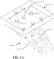
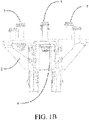
- FIGs. 1A-1C which consist of a main outer portion 2 of the fitting 3, and an inner nested portion 4.
- This structure requires the interface between these inner and outer portions to include three surfaces orthogonal to each other. For machined parts this requires tighter tolerances that are expensive to meet and result in a higher rate of rejection, as well as necessitating shimming of designed in gaps.
- the fasteners 5 common to both portions of the fitting and the mating part 6 must penetrate a thicker stack than the fasteners 7 solely penetrating the outer portion preventing the use of a single grip length without other structural adaptation. Varying grip lengths makes for a more complicated, slower, and more expensive assembly.
- Exemplary implementations of a three piece failsafe clevis include a center portion having a center top surface, a planar first outer surface and a planar second outer surface.
- the second outer surface is oppositely oriented to the first outer surface.
- a channel in the center portion is configured to receive a tension and compression member.
- a left lateral portion is connected adjacent the first outer surface.
- the left lateral portion has a planar first inner surface received against the first outer surface and a left top surface coplanar with the center top surface.
- a right lateral portion is connected adjacent the second outer surface.
- the right later portion has a planar second inner surface received against the second outer surface and a right top surface coplanar with the center top surface.
- the exemplary implementations provide a method for engaging a tension and compression member with a three piece failsafe clevis.
- a center portion having a center top surface is received on a lower surface of a wing, the center portion having a left inner flange and left inner tang with a planar first outer surface and a right inner flange and left inner tang with a planar second outer surface, said second outer surface oppositely oriented to the first outer surface.
- a left lateral portion is connected adjacent the first outer surface using a first plurality of field fasteners with a left outer flange and a left outer tang having a planar first inner surface received against the first outer surface and a left top surface coplanar with the center top surface and received on the lower surface.
- a right lateral portion is connected adjacent the second outer surface using a second plurality of field fasteners with a right outer flange and a right outer tang having a planar first inner surface received against the first outer surface and a right top surface coplanar with the center top surface and received on the lower surface.
- the tension and compression member is received in a channel between the left inner tang and right inner tang in the center portion.
- the implementations described herein provide an underwing support with a three piece failsafe clevis incorporating three laterally adjacent components which simplifies the assembly process and reduces or eliminates the need to include designed-in gaps that may need to be shimmed.
- Common flange thickness in all three laterally adjacent components allows the use of a single, common grip length fasteners.
- the three piece failsafe clevis maintains necessary structural performance characteristics and compliance to fail safe requirements.
- implementations are described herein with reference to an underwing support structure for a flap system, implementations may be applicable to any Principal Structural Element (PSE).
- PSE Principal Structural Element
- FIGs. 2A, 2B and 2C depict an aircraft 10 having a wing 12 with a system of operating flaps 14.
- the flaps 14 are engaged to the wing 12 at multiple attachment points with flap supports 15a, 15b at least partially housed within fixed fairings 16a and movable fairings 16b.
- the flaps 14 are deployed to enhance aerodynamic performance during takeoff and landing with a flap actuation mechanism 18 that causes the flaps 14 and movable fairings 16b to rotate rearward and downward relative to the wing 12.
- the flap supports 15a, 15b extending from the structure of the wing 12 each incorporate an underwing fitting employing a three piece failsafe clevis 20, as will be described in greater detail subsequently.
- a rotary actuator 22 with a drive arm 24 radially extending from the actuator to rotate upon activation of the actuator, is supported between a pair of flap support ribs 23 (the outboard flap support rib removed for clarity).
- the flap support ribs 23 are connected to the aft spar 25 proximate an upper flange 27.
- a coupler link 26 is pivotally attached at a leading end to the drive arm 24 with a pivot pin 29 whereby rotation of the actuator rotates the drive arm 24 to extend the coupler link 26.
- a spherical bearing or similar engagement element in the leading end of the coupler link 26 may be employed to accommodate angular alignment.
- the flap 14 is mounted on a carrier beam 30 and rotatably coupled through the flap support ribs 23 to the wing 12.
- the carrier beam 30 is rotatably attached with an axle 32 at a lower vertex 34 to a trailing clevis 36 formed by the inboard and outboard ribs 23.
- the coupler link 26 extends from the drive arm 24 to the carrier beam 30 and is pivotally attached to the carrier beam with a second pivot pin 33.
- the three piece failsafe clevis 20 attached to a lower surface 35 of the wing 12 provides tension support at the trailing clevis 36 with a tension and compression member 37 or other structural link connected with a pin 38 to the trailing clevis 36.
- the tension and compression member 37 is engaged by the failsafe clevis 20 with frangible pins 39a and 39b for ground contact safety.
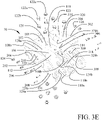
- FIGs. 3A-3E An example implementation of the three piece failsafe clevis 20 is seen in FIGs. 3A-3E .
- the three piece failsafe clevis 20 has a center portion 102 with a center top flange 104.
- a body portion 106 has a left inner flange 108a and a right inner flange 108b perpendicularly depending from the center top flange 104.
- a left inner tang 110a extends rearward from the left inner flange 108a and a right inner tang 110b extends rearward from the right inner flange 108b.
- the left inner flange 108a and the left inner tang 110a have a planar first outer surface 112 while the right inner flange 108b and the right inner tang 110b have a planar second outer surface 114 parallel to and oppositely oriented to the first outer surface 112.
- a right inner surface 116a of left inner tang 110a and a left inner surface 116b of right inner tang 110b straddle a channel 118 configured to receive the tension and compression member 37.
- a left lateral portion 202 is connected adjacent the first outer surface 112 of center portion 102 while a right lateral portion 302 is connected adjacent the second outer surface 114 of center portion 102 opposite from the left lateral portion 202.
- Left lateral portion 202 has a left top flange 204.
- a left outer flange 206 perpendicularly depends from the left top flange 204 and a left outer tang 208 extends rearward from the left outer flange 206.
- Left outer flange 206 and left outer tang 208 commonly form a planar first inner surface 209. First inner surface 209 of the left lateral portion 202 is received against the first outer surface 112 of center portion 102.
- Right lateral portion 302 has a right top flange 304.
- a right outer flange 306 perpendicularly depends from the right top flange 304 and a right outer tang 308 extend rearward from the left outer flange 206.
- Right outer flange 306 and right outer tang 308 commonly form a planar second inner surface 309. Second inner surface 309 of the right lateral portion 302 is received against the second outer surface 114 of the center portion 102.
- a left top surface 210 of the left top flange 204 and a right top surface 310 of the right top flange 304 are coplanar with a center top surface 111 of the center top flange 104. This provides a single planar top surface 113 for the three piece failsafe clevis 20.
- the center top flange 104 has a first plurality of holes 120 configured to receive a first plurality of fasteners 122a.
- the left top flange 204 has a plurality of holes 220 to receive a second plurality of fasteners 122b and the right top flange 304 has a third plurality of holes 320 to receive a third plurality of fasteners 122c.
- a first thickness 130 of the center top flange 104, a second thickness 230 of the left top flange 204 and a third thickness 330 of the right top flange 304 are equal. This allows the first, second and third pluralities of fasteners, 122a, 122b and 122c to have an equal grip length 123 for attachment to the underwing skin.
- the left lateral portion 202 is affixed to the center portion 102 with a first plurality of field fasteners 124 while the right lateral portion 302 is fixed to the center portion 102 with a second plurality of field fasteners 126.
- a first array of holes 128a in the left inner flange 108a is in concentric alignment with a first mating array of holes 228a in the left outer flange 206.
- a second array of holes 128b in the right inner flange 108b is in concentric alignment with a second mating array of holes 328b in the right outer flange 306.
- a third array of holes 129a in the left inner tang 110a is in concentric alignment with a third mating array of holes 229a in the left outer tang 208.
- a fourth array of holes 129b in the right inner tang 110b is in concentric alignment with a fourth mating array of holes 329b in the right outer tang 308.
- the first array of holes 128a, first mating array of holes 228a, third array of holes 129a and third mating array of holes 229a receive the first plurality of field fasteners 124.
- the second array of holes 128b, second mating array of holes 328b, fourth array of holes 129b and fourth mating array of holes 329b receive the second plurality of field fasteners 126.
- a first pair of receiving holes 140a and 140b in the first and second inner tangs 110a and 110b are concentrically aligned with a first mating receiving hole 240 in the left outer tang 208 and a second mating receiving hole 340 in the right outer tang 308 and a second pair of receiving holes 142a and 142b are concentrically aligned with a third mating receiving hole 242 in the left outer tang 208 and a fourth mating receiving hole 342 in the right outer tang 308.
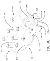
- a single pair of receiving holes 150a and 150b in the first and second inner tangs 110a and 110b concentrically aligned with a first mating receiving hole 250 in the left outer tang 208 and a second mating receiving hole 350 in the right outer tang 308 may be employed for a single pin engagement.
- geometric arrangement of the first mating array of holes 228a, second mating array of holes 328a, third mating array of holes 229a and fourth mating array of holes 329b is configured to surround potential propagating cracks in either the left or right outer flanges 206, 306 or the left or right outer tangs 208, 308 for transfer or load through the respective field fasteners to the left or right inner flanges 108a, 108b or left or right inner tangs 110a, 110b.
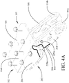
- Example crack 400 is shown in the left outer flange and left outer tang.
- geometric arrangement of the first array of holes 128a, second array of holes 128b, third array of holes 129a and fourth array of holes 129b is configured to surround potential propagating cracks in either the left or right inner flanges 108a, 108b or the left or right inner tangs 110a, 110b for transfer or load through the respective field fasteners to the left or right outer flanges 206, 306 or left or right outer tangs 208, 308.
- planar first inner surface 209 and first outer surface 112 and second inner surface 309 and second outer surface 114 provides very high tolerance engagement of the center portion 102, left lateral portion 202 and right lateral portion 302, limited only by machining tolerances of the planar surfaces.
- very high tolerance is maintained in the planar top surface 113 with engagement of the center top surface 111, left top surface 210 and right top surface 310 on a high tolerance surface plate during installation of the field fasteners.
- Thickness of the left or right outer flanges 208, 308 or the left or right outer tangs 208, 308, the left or right inner flanges 108a, 108b and the left or right inner tangs 110a, 110b may vary to accommodate fatigue mitigation.
- an outer flange forward thickness 240, 340 expands into an aft outer tang thickness 242, 342.
- a forward inner flange thickness 140a, 140b expands into an aft inner tang thickness 142a, 142b.
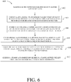
- the implementations described provide a method 600 of engaging a tension and compression member with a three piece failsafe clevis as shown in FIG. 6 .
- a center portion having a center top surface is received on a lower surface of a wing, step 602,
- the center portion has a left inner flange and left inner tang with a planar first outer surface and a right inner flange and left inner tang with a planar second outer surface, said second outer surface oppositely oriented to the first outer surface.
- a left lateral portion is connected adjacent the first outer surface using a first plurality of field fasteners with a left outer flange and a left outer tang having a planar first inner surface received against the first outer surface and a left top surface coplanar with the center top surface to be received on the lower surface of the wing, step 604.
- a right lateral portion is connected adjacent the second outer surface using a second plurality of field fasteners with a right outer flange and a right outer tang having a planar first inner surface received against the first outer surface and a right top surface coplanar with the center top surface to be received on the lower surface of the wing, step 606.
- a first array of holes in the left inner flange of the left portion is concentrically aligned with a first mating array of holes in the left outer flange
- a second array of holes in the right inner flange is concentrically aligned with a second mating array of holes in the right outer flange, step 608.
- a third array of holes in the left inner tang is concentrically aligned with a third mating array of holes in the left outer tang and a fourth array of holes in the right inner tang is concentrically aligned with a fourth mating array of holes in the right outer tang, step 610.
- Geometric arrangement of the first mating array of holes, second mating array of holes, third mating array of holes and fourth mating array of holes is configured to surround potential propagating cracks in either the left or right outer flanges or the left or right outer tangs.
- Geometric arrangement of the first array of holes, second array of holes, third array of holes and fourth array of holes is configured to surround potential propagating cracks in either the left or right inner flanges, or the left or right inner tangs.
- the tension and compression member is received in a channel between the left inner tang and right inner tang in the center portion, step 612.
Landscapes
- Engineering & Computer Science (AREA)
- Aviation & Aerospace Engineering (AREA)
- General Engineering & Computer Science (AREA)
- Manufacturing & Machinery (AREA)
- Mechanical Engineering (AREA)
- Transportation (AREA)
- Connection Of Plates (AREA)
- Packaging Of Machine Parts And Wound Products (AREA)
Abstract
Description
- This disclosure relates generally to the field of aircraft deployment systems having an underwing support with a three piece failsafe clevis.
- Aircraft employ deployment systems to articulate surfaces. For example commercial aircraft have flaps which deploy to increase camber and chord of the wings for enhanced performance in take-off and landing. Various mechanical arrangements have been developed to deploy the flaps from retracted to extended positions. Flap supports typically extend below the lower surface of the wing and deployment of the flaps extend portions of the flap and flap support elements below the wing. Principle structural elements (PSE) in the flap support elements are subject to failsafe requirements. This can mean "back to back" duplication of sections of the structure which are primarily loaded in tension. For a lug this is a relatively simple addition to the design but for a clevis it becomes more complicated, expensive, and difficult to build.
- Examples can be found on existing commercial aircraft of failsafe clevises used in an underwing support fitting as seen in
FIGs. 1A-1C which consist of a mainouter portion 2 of thefitting 3, and an innernested portion 4. This structure requires the interface between these inner and outer portions to include three surfaces orthogonal to each other. For machined parts this requires tighter tolerances that are expensive to meet and result in a higher rate of rejection, as well as necessitating shimming of designed in gaps. Additionally, thefasteners 5 common to both portions of the fitting and themating part 6 must penetrate a thicker stack than thefasteners 7 solely penetrating the outer portion preventing the use of a single grip length without other structural adaptation. Varying grip lengths makes for a more complicated, slower, and more expensive assembly. - It is therefore desirable to provide an underwing support which overcomes these shortcomings in the prior art.
- Exemplary implementations of a three piece failsafe clevis include a center portion having a center top surface, a planar first outer surface and a planar second outer surface. The second outer surface is oppositely oriented to the first outer surface. A channel in the center portion is configured to receive a tension and compression member. A left lateral portion is connected adjacent the first outer surface. The left lateral portion has a planar first inner surface received against the first outer surface and a left top surface coplanar with the center top surface. A right lateral portion is connected adjacent the second outer surface. The right later portion has a planar second inner surface received against the second outer surface and a right top surface coplanar with the center top surface.
- The exemplary implementations provide a method for engaging a tension and compression member with a three piece failsafe clevis. A center portion having a center top surface is received on a lower surface of a wing, the center portion having a left inner flange and left inner tang with a planar first outer surface and a right inner flange and left inner tang with a planar second outer surface, said second outer surface oppositely oriented to the first outer surface. A left lateral portion is connected adjacent the first outer surface using a first plurality of field fasteners with a left outer flange and a left outer tang having a planar first inner surface received against the first outer surface and a left top surface coplanar with the center top surface and received on the lower surface. A right lateral portion is connected adjacent the second outer surface using a second plurality of field fasteners with a right outer flange and a right outer tang having a planar first inner surface received against the first outer surface and a right top surface coplanar with the center top surface and received on the lower surface. The tension and compression member is received in a channel between the left inner tang and right inner tang in the center portion.
- The features, functions, and advantages that have been discussed can be achieved independently in various implementations or may be combined in yet other implementations further details of which can be seen with reference to the following description and drawings.
-
FIG. 1A is a rear pictorial view of a prior art underwing support fitting; -
FIG. 1B is a rear view of the prior art underwing support fitting ofFIG. 1A ; -
FIG. 1C is an exploded view of the components of the underwing support fitting ofFIG. 1A ; -
FIG. 2A is a representation of an aircraft in which the implementations disclosed herein may be employed; -
FIG. 2B is a top view of the wing and flaps of the aircraft ofFIG. 2A ; -
FIG. 2C is a side detailed view (with the fairings removed) of a flap structure incorporating an underwing support fitting for which the disclosed implementations may be employed; -
FIG. 3A is a rear pictorial view of a three piece failsafe clevis for an underwing support fitting; -
FIG. 3B is a rear view of the three piece failsafe clevis ofFIG. 3A ; -
FIG. 3C is a bottom view of the three piece failsafe clevis ofFIG. 3A ; -
FIG. 3D is a side view of the three piece failsafe clevis ofFIG. 3A ; -
FIG. 3E is a rear left exploded view of the components of the three piece failsafe clevis ofFIG. 3A ; -
FIG. 3F is a rear right exploded view of the components of the three piece failsafe clevis ofFIG. 3A ; -
FIG. 3G is a rear pictorial view demonstrating an alternative configuration of the clevis for a single pin engagement; -
FIG. 4A is a pictorial view of a first failsafe condition with a crack in one of the outer components of the example implementation; -
FIG. 4B is a side view of the first failsafe condition; -
FIG. 5 is a pictorial view of a second failsafe condition with a crack in the center component of the example implementation; and -
FIG. 6 is a flow chart of a method for engaging a tension and compression member with a three piece failsafe clevis. - The implementations described herein provide an underwing support with a three piece failsafe clevis incorporating three laterally adjacent components which simplifies the assembly process and reduces or eliminates the need to include designed-in gaps that may need to be shimmed. Common flange thickness in all three laterally adjacent components allows the use of a single, common grip length fasteners. The three piece failsafe clevis maintains necessary structural performance characteristics and compliance to fail safe requirements.
- While implementations are described herein with reference to an underwing support structure for a flap system, implementations may be applicable to any Principal Structural Element (PSE).
- Referring to the drawings,
FIGs. 2A, 2B and2C depict anaircraft 10 having awing 12 with a system of operating flaps 14. Theflaps 14 are engaged to thewing 12 at multiple attachment points with flap supports 15a, 15b at least partially housed within fixedfairings 16a andmovable fairings 16b. Theflaps 14 are deployed to enhance aerodynamic performance during takeoff and landing with a flap actuation mechanism 18 that causes theflaps 14 andmovable fairings 16b to rotate rearward and downward relative to thewing 12. - As seen in
FIG. 2C , with thefairings wing 12 each incorporate an underwing fitting employing a three piecefailsafe clevis 20, as will be described in greater detail subsequently. In the example shown, arotary actuator 22, with adrive arm 24 radially extending from the actuator to rotate upon activation of the actuator, is supported between a pair of flap support ribs 23 (the outboard flap support rib removed for clarity). Theflap support ribs 23 are connected to theaft spar 25 proximate anupper flange 27. Acoupler link 26 is pivotally attached at a leading end to thedrive arm 24 with a pivot pin 29 whereby rotation of the actuator rotates thedrive arm 24 to extend thecoupler link 26. - A spherical bearing or similar engagement element in the leading end of the
coupler link 26 may be employed to accommodate angular alignment. Theflap 14 is mounted on acarrier beam 30 and rotatably coupled through theflap support ribs 23 to thewing 12. Thecarrier beam 30 is rotatably attached with anaxle 32 at alower vertex 34 to a trailingclevis 36 formed by the inboard andoutboard ribs 23. Thecoupler link 26 extends from thedrive arm 24 to thecarrier beam 30 and is pivotally attached to the carrier beam with asecond pivot pin 33. - In the example shown, the three piece
failsafe clevis 20 attached to alower surface 35 of thewing 12 provides tension support at the trailingclevis 36 with a tension andcompression member 37 or other structural link connected with a pin 38 to the trailingclevis 36. The tension andcompression member 37 is engaged by thefailsafe clevis 20 withfrangible pins - An example implementation of the three piece
failsafe clevis 20 is seen inFIGs. 3A-3E . The three piecefailsafe clevis 20 has acenter portion 102 with a centertop flange 104. Abody portion 106 has a leftinner flange 108a and a rightinner flange 108b perpendicularly depending from the centertop flange 104. A leftinner tang 110a extends rearward from the leftinner flange 108a and a rightinner tang 110b extends rearward from the rightinner flange 108b. The leftinner flange 108a and the leftinner tang 110a have a planar firstouter surface 112 while the rightinner flange 108b and the rightinner tang 110b have a planar secondouter surface 114 parallel to and oppositely oriented to the firstouter surface 112. A right inner surface 116a of leftinner tang 110a and a left inner surface 116b of rightinner tang 110b straddle achannel 118 configured to receive the tension andcompression member 37. - A left
lateral portion 202 is connected adjacent the firstouter surface 112 ofcenter portion 102 while a rightlateral portion 302 is connected adjacent the secondouter surface 114 ofcenter portion 102 opposite from the leftlateral portion 202. Leftlateral portion 202 has a lefttop flange 204. A leftouter flange 206 perpendicularly depends from the lefttop flange 204 and a leftouter tang 208 extends rearward from the leftouter flange 206. Leftouter flange 206 and leftouter tang 208 commonly form a planar first inner surface 209. First inner surface 209 of the leftlateral portion 202 is received against the firstouter surface 112 ofcenter portion 102. - Right
lateral portion 302 has a righttop flange 304. A rightouter flange 306 perpendicularly depends from the righttop flange 304 and a rightouter tang 308 extend rearward from the leftouter flange 206. Rightouter flange 306 and rightouter tang 308 commonly form a planar secondinner surface 309. Secondinner surface 309 of the rightlateral portion 302 is received against the secondouter surface 114 of thecenter portion 102. - A left
top surface 210 of the lefttop flange 204 and a righttop surface 310 of the righttop flange 304 are coplanar with a centertop surface 111 of the centertop flange 104. This provides a single planartop surface 113 for the three piecefailsafe clevis 20. The centertop flange 104 has a first plurality ofholes 120 configured to receive a first plurality offasteners 122a. The lefttop flange 204 has a plurality ofholes 220 to receive a second plurality offasteners 122b and the righttop flange 304 has a third plurality ofholes 320 to receive a third plurality offasteners 122c. Afirst thickness 130 of the centertop flange 104, asecond thickness 230 of the lefttop flange 204 and athird thickness 330 of the righttop flange 304 are equal. This allows the first, second and third pluralities of fasteners, 122a, 122b and 122c to have anequal grip length 123 for attachment to the underwing skin. - The left
lateral portion 202 is affixed to thecenter portion 102 with a first plurality offield fasteners 124 while the rightlateral portion 302 is fixed to thecenter portion 102 with a second plurality offield fasteners 126. - A first array of
holes 128a in the leftinner flange 108a is in concentric alignment with a first mating array ofholes 228a in the leftouter flange 206. Similarly, a second array ofholes 128b in the rightinner flange 108b is in concentric alignment with a second mating array ofholes 328b in the rightouter flange 306. - A third array of holes 129a in the left
inner tang 110a is in concentric alignment with a third mating array ofholes 229a in the leftouter tang 208. Similarly, a fourth array ofholes 129b in the rightinner tang 110b is in concentric alignment with a fourth mating array ofholes 329b in the rightouter tang 308. - The first array of
holes 128a, first mating array ofholes 228a, third array of holes 129a and third mating array ofholes 229a receive the first plurality offield fasteners 124. Similarly, the second array ofholes 128b, second mating array ofholes 328b, fourth array ofholes 129b and fourth mating array ofholes 329b receive the second plurality offield fasteners 126. - In the described example implementation for engagement of the
frangible pins holes inner tangs mating receiving hole 240 in the leftouter tang 208 and a secondmating receiving hole 340 in the rightouter tang 308 and a second pair of receivingholes 142a and 142b are concentrically aligned with a thirdmating receiving hole 242 in the leftouter tang 208 and a fourthmating receiving hole 342 in the rightouter tang 308. In alternative implementations as shown inFIG. 3G , a single pair of receivingholes inner tangs mating receiving hole 250 in the leftouter tang 208 and a secondmating receiving hole 350 in the rightouter tang 308 may be employed for a single pin engagement. - As seen in
FIGs, 4A and4B , geometric arrangement of the first mating array ofholes 228a, second mating array of holes 328a, third mating array ofholes 229a and fourth mating array ofholes 329b is configured to surround potential propagating cracks in either the left or rightouter flanges outer tangs inner flanges inner tangs Example crack 400 is shown in the left outer flange and left outer tang. - Similarly, as seen in
FIG. 5 , geometric arrangement of the first array ofholes 128a, second array ofholes 128b, third array of holes 129a and fourth array ofholes 129b is configured to surround potential propagating cracks in either the left or rightinner flanges inner tangs outer flanges outer tangs - The engagement of planar first inner surface 209 and first
outer surface 112 and secondinner surface 309 and secondouter surface 114 provides very high tolerance engagement of thecenter portion 102, leftlateral portion 202 and rightlateral portion 302, limited only by machining tolerances of the planar surfaces. Similarly, very high tolerance is maintained in the planartop surface 113 with engagement of the centertop surface 111, lefttop surface 210 and righttop surface 310 on a high tolerance surface plate during installation of the field fasteners. - Thickness of the left or right
outer flanges outer tangs inner flanges inner tangs FIG. 3C , an outer flange forwardthickness outer tang thickness inner flange thickness inner tang thickness 142a, 142b. - The implementations described provide a
method 600 of engaging a tension and compression member with a three piece failsafe clevis as shown inFIG. 6 . A center portion having a center top surface is received on a lower surface of a wing,step 602, The center portion has a left inner flange and left inner tang with a planar first outer surface and a right inner flange and left inner tang with a planar second outer surface, said second outer surface oppositely oriented to the first outer surface. - A left lateral portion is connected adjacent the first outer surface using a first plurality of field fasteners with a left outer flange and a left outer tang having a planar first inner surface received against the first outer surface and a left top surface coplanar with the center top surface to be received on the lower surface of the wing,
step 604. - A right lateral portion is connected adjacent the second outer surface using a second plurality of field fasteners with a right outer flange and a right outer tang having a planar first inner surface received against the first outer surface and a right top surface coplanar with the center top surface to be received on the lower surface of the wing,
step 606. - A first array of holes in the left inner flange of the left portion is concentrically aligned with a first mating array of holes in the left outer flange, a second array of holes in the right inner flange is concentrically aligned with a second mating array of holes in the right outer flange,
step 608. - A third array of holes in the left inner tang is concentrically aligned with a third mating array of holes in the left outer tang and a fourth array of holes in the right inner tang is concentrically aligned with a fourth mating array of holes in the right outer tang,
step 610. - Geometric arrangement of the first mating array of holes, second mating array of holes, third mating array of holes and fourth mating array of holes is configured to surround potential propagating cracks in either the left or right outer flanges or the left or right outer tangs.
- Geometric arrangement of the first array of holes, second array of holes, third array of holes and fourth array of holes is configured to surround potential propagating cracks in either the left or right inner flanges, or the left or right inner tangs. The tension and compression member is received in a channel between the left inner tang and right inner tang in the center portion,
step 612. - The disclosure includes, without limitation, example implementations in accordance with the following Clauses:
- Clause 1. A three piece failsafe clevis (20), comprising:
- a center portion (102) having a center top surface (104), a planar first outer surface (112) and a planar second outer surface (114), said second outer surface oppositely oriented to the first outer surface, and a channel (118) configured to receive a tension and compression member (37);
- a left lateral portion (202) connected adjacent the first outer surface and having a planar first inner surface (209) received against the first outer surface and a left top surface (210) coplanar with the center top surface; and
- a right lateral portion (302) connected adjacent the second outer surface and having a planar second inner surface (309) received against the second outer surface and a right top surface (310) coplanar with the center top surface.
-
Clause 2. The three piece failsafe clevis as defined in Clause 1, wherein the center portion comprises:- a center top flange (104) having the center top surface; and
- a body portion (106) having a left inner flange (108a) and a right inner flange (108b) perpendicularly depending from the center top flange;
- a left inner tang (110a) extending rearward from the left inner flange and a right inner tang (110b) extending rearward from the right inner flange;
- wherein the left inner flange and the left inner tang commonly form the planar first outer surface and the right inner flange and the right inner tang commonly form the planar second outer surface.
-
Clause 3. The three piece failsafe clevis as defined inClause 2, wherein the left lateral portion comprises:- a left top flange (204) having the left top surface;
- a left outer flange (206) perpendicularly depending from the left top flange; and
- a left outer tang (208) extending rearward from the left outer flange, wherein the left outer flange and the left outer tang commonly form the planar first inner surface.
-
Clause 4. The three piece failsafe clevis as defined inClause 3, wherein the right lateral portion comprises:- a right top flange (304) having the right top surface;
- a right outer flange (306) perpendicularly depending from the right top flange; and
- a right outer tang (308) extending rearward from the right outer flange, wherein the right outer flange and the right outer tang commonly form the planar second inner surface.
-
Clause 5. The three piece failsafe clevis as defined inClause 4, wherein the center top flange has a first thickness (130), left top flange has a second thickness (230) and the right top flange has a third thickness (330), the first, second and third thicknesses being equal. -
Clause 6. The three piece failsafe clevis as defined inClause 5, wherein the center top flange has a first plurality of holes (120) configured to a first plurality of fasteners (122a), the left top flange has a plurality of holes (220) to receive a second plurality of fasteners (122b) and the right top flange has a third plurality of holes (320) to receive a third plurality of fasteners (122c), wherein the first plurality of fasteners, second plurality of fasteners and third plurality of fasteners have an equal grip length (123). -
Clause 7. The three piece failsafe clevis as defined in any of Clauses 4-6, wherein- a first array of holes (128a) in the left inner flange is in concentric alignment with a first mating array of holes (228a) in the left outer flange;
- a second array of holes in the right inner flange (128b) is in concentric alignment with a second mating array of holes (328a) in the right outer flange;
- a third array of holes in the left inner tang (129a) is in concentric alignment with a third mating array of holes (229a) in the left outer tang; and
- a fourth array of holes in the right inner tang (129b) is in concentric alignment with a fourth mating array of holes (329b) in the right outer tang.
- Clause 8. The three piece failsafe clevis as defined in
claim 7, wherein- the first array of holes, first mating array of holes, third array of holes and third mating array of holes receive a first plurality of field fasteners (124) to affix the left lateral portion to the center portion; and,
- the second array of holes, second mating array of holes, fourth array of holes and fourth mating array of holes receive a second plurality of field fasteners (126) to affix the right lateral portion to the center portion.
- Clause 9. The three piece failsafe clevis as defined in Clause 8, wherein the geometric arrangement of the first mating array of holes, second mating array of holes, third mating array of holes and fourth mating array of holes is configured to surround potential propagating cracks in either the left or right outer flanges or the left or right outer tangs.
-
Clause 10. The three piece failsafe clevis as defined in Clause 8, wherein the geometric arrangement of the first array of holes, second array of holes, third array of holes and fourth array of holes is configured to surround potential propagating cracks in either the left or right inner flanges, or the left or right inner tangs. - Clause 11. An aircraft (10) having a wing (12) with a system of operating flaps, said system comprising:
- a plurality of flaps (14) each having a plurality of flap supports (16a, 16b);
- at least one actuator (22) supported in at least one of the plurality of flap supports;
- at least one carrier beam (30) to support one of said plurality of flaps, said carrier beam rotatably engaged in at least one flap support rib (23);
- a tension and compression link (37) engaged to the flap support rib:
- a three piece failsafe clevis (20) connected to a lower surface (35) of the wing and having
- a center portion (102) having a center top surface (111) received on the lower surface, a planar first outer surface (112) and a planar second outer surface (114), said second outer surface oppositely oriented to the first outer surface, and a channel (118) configured to receive a tension and compression link (37);
- a left lateral portion (202) connected adjacent the first outer surface and having a planar first inner surface (209) received against the first outer surface and a left top surface (210) coplanar with the center top surface and received on the lower surface; and
- a right lateral portion (302) connected adjacent the second outer surface and having a planar second inner surface (309) received against the second outer surface and a right top surface (310) coplanar with the center top surface and received on the lower surface.
-
Clause 12. The aircraft as defined in Clause 11, wherein the left lateral portion comprises:- a left top flange (204) having the left top surface;
- a left outer flange (206) perpendicularly depending from the left top flange; and
- a left outer tang (208) extending rearward from the left outer flange, wherein the left outer flange and the left outer tang commonly form the planar first inner surface.
- Clause 13. The aircraft as defined in
claim 12, wherein the right lateral portion comprises:- a right top flange (304) having the right top surface;
- a right outer flange (306) perpendicularly depending from the right top flange; and
- a right outer tang (308) extending rearward from the right outer flange, wherein the right outer flange and the right outer tang commonly form the planar second inner surface.
-
Clause 14. The aircraft as defined in Clause 13, wherein the center top flange has a first thickness (130), left top flange has a second thickness (230) and the right top flange has a third thickness (330), the first, second and third thicknesses being equal. - Clause 15. The aircraft as defined in
Clause 14, wherein the center top flange has a first plurality of holes (120) configured to a first plurality of fasteners (122a), the left top flange has a second plurality of holes (220) to receive a second plurality of fasteners (122b) and the right top flange has a third plurality of holes (320) to receive a third plurality of fasteners (122c), wherein the first plurality of fasteners, second plurality of fasteners and third plurality of fasteners have an equal grip length (123) for connection to the lower surface. - Clause 16. A method for engaging a tension and compression member with a three piece failsafe clevis, the method comprising:
- receiving a center portion having a center top surface on a lower surface of a wing, the center portion having a left inner flange and left inner tang with a planar first outer surface and a right inner flange and left inner tang with a planar second outer surface, said second outer surface oppositely oriented to the first outer surface;
- connecting a left lateral portion adjacent the first outer surface using a first plurality of field fasteners with a left outer flange and a left outer tang having a planar first inner surface received against the first outer surface and a left top surface coplanar with the center top surface and received on the lower surface;
- connecting a right lateral portion adjacent the second outer surface using a second plurality of field fasteners with a right outer flange and a right outer tang having a planar first inner surface received against the first outer surface and a right top surface coplanar with the center top surface and received on the lower surface; and
- receiving the tension and compression member in a channel between the left inner tang and right inner tang in the center portion.
- Clause 17. The method as defined in Clause 16, further comprising:
- concentrically aligning a first array of holes in the left inner flange of the left portion with a first mating array of holes in the left outer flange; and
- concentrically aligning a second array of holes in the right inner flange a second mating array of holes in the right outer flange.
- Clause 18. The method as defined in Clause 17, further comprising:
- concentrically aligning a third array of holes in the left inner tang with a third mating array of holes in the left outer tang; and
- concentrically aligning a fourth array of holes in the right inner tang with a fourth mating array of holes in the right outer tang.
- Clause 19. The method as defined in Clause 18, further comprising:
geometrically arranging the first mating array of holes, second mating array of holes, third mating array of holes and fourth mating array of holes to surround potential propagating cracks in either the left or right outer flanges or the left or right outer tangs. -
Clause 20. The method as defined in Clause 19, further comprising geometrically arranging the first array of holes, second array of holes, third array of holes and fourth array of holes to surround potential propagating cracks in either the left or right inner flanges, or the left or right inner tangs. - Having now described various implementations in detail as required by the patent statutes, those skilled in the art will recognize modifications and substitutions to the specific implementations disclosed herein. Such modifications are within the scope and intent of the following claims. Within the specification and the claims, the terms "comprising", "incorporate", "incorporates" or "incorporating", "include", "includes" or "including", "has", "have" or "having", and "contain", "contains" or "containing" are intended to be open recitations and additional or equivalent elements may be present. The term "substantially" as used within the specification and claims means that the recited characteristic, parameter, or value need not be achieved exactly, but that deviations or variations, including for example, tolerances, measurement error, measurement accuracy limitations and other factors known to those skilled in the art, may occur in amounts that do not preclude the effect the characteristic was intended to provide. As used herein the terms "outboard" and "inboard" and "upper" and "lower" are employed to describe relative positioning and other than for the specific implementations disclosed may be substituted with appropriate descriptors such as "first" and "second", "top" and "bottom" or "right" and "left" depending on orientation of actual implementation.
Claims (15)
- A three piece failsafe clevis (20), comprising:a center portion (102) having a center top surface (104), a planar first outer surface (112) and a planar second outer surface (114), said second outer surface oppositely oriented to the first outer surface, and a channel (118) configured to receive a tension and compression member (37);a left lateral portion (202) connected adjacent the first outer surface and having a planar first inner surface (209) received against the first outer surface and a left top surface (210) coplanar with the center top surface; anda right lateral portion (302) connected adjacent the second outer surface and having a planar second inner surface (309) received against the second outer surface and a right top surface (310) coplanar with the center top surface.
- The three piece failsafe clevis as defined in claim 1, wherein the center portion comprises:a center top flange (104) having the center top surface; anda body portion (106) having a left inner flange (108a) and a right inner flange (108b) perpendicularly depending from the center top flange;a left inner tang (110a) extending rearward from the left inner flange and a right inner tang (110b) extending rearward from the right inner flange;wherein the left inner flange and the left inner tang commonly form the planar first outer surface and the right inner flange and the right inner tang commonly form the planar second outer surface.
- The three piece failsafe clevis as defined in claim 2, wherein the left lateral portion comprises:a left top flange (204) having the left top surface;a left outer flange (206) perpendicularly depending from the left top flange; anda left outer tang (208) extending rearward from the left outer flange, wherein the left outer flange and the left outer tang commonly form the planar first inner surface.
- The three piece failsafe clevis as defined in claim 3, wherein the right lateral portion comprises:a right top flange (304) having the right top surface;a right outer flange (306) perpendicularly depending from the right top flange; anda right outer tang (308) extending rearward from the right outer flange, wherein the right outer flange and the right outer tang commonly form the planar second inner surface.
- The three piece failsafe clevis as defined in claim 4, wherein the center top flange has a first thickness (130), left top flange has a second thickness (230) and the right top flange has a third thickness (330), the first, second and third thicknesses being equal.
- The three piece failsafe clevis as defined in claim 5, wherein the center top flange has a first plurality of holes (120) configured to a first plurality of fasteners (122a), the left top flange has a plurality of holes (220) to receive a second plurality of fasteners (122b) and the right top flange has a third plurality of holes (320) to receive a third plurality of fasteners (122c), wherein the first plurality of fasteners, second plurality of fasteners and third plurality of fasteners have an equal grip length (123).
- The three piece failsafe clevis as defined in any of claims 4-6, whereina first array of holes (128a) in the left inner flange is in concentric alignment with a first mating array of holes (228a) in the left outer flange;a second array of holes in the right inner flange (128b) is in concentric alignment with a second mating array of holes (328a) in the right outer flange;a third array of holes in the left inner tang (129a) is in concentric alignment with a third mating array of holes (229a) in the left outer tang; anda fourth array of holes in the right inner tang (129b) is in concentric alignment with a fourth mating array of holes (329b) in the right outer tang.
- An aircraft (10) having a wing (12) with a system of operating flaps, said system comprising:a plurality of flaps (14) each having a plurality of flap supports (16a, 16b);at least one actuator (22) supported in at least one of the plurality of flap supports;at least one carrier beam (30) to support one of said plurality of flaps, said carrier beam rotatably engaged in at least one flap support rib (23);a tension and compression link (37) engaged to the flap support rib:a three piece failsafe clevis (20) connected to a lower surface (35) of the wing and havinga center portion (102) having a center top surface (111) received on the lower surface, a planar first outer surface (112) and a planar second outer surface (114), said second outer surface oppositely oriented to the first outer surface, and a channel (118) configured to receive a tension and compression link (37);a left lateral portion (202) connected adjacent the first outer surface and having a planar first inner surface (209) received against the first outer surface and a left top surface (210) coplanar with the center top surface and received on the lower surface; anda right lateral portion (302) connected adjacent the second outer surface and having a planar second inner surface (309) received against the second outer surface and a right top surface (310) coplanar with the center top surface and received on the lower surface.
- The aircraft as defined in claim 8, wherein the left lateral portion comprises:a left top flange (204) having the left top surface;a left outer flange (206) perpendicularly depending from the left top flange; anda left outer tang (208) extending rearward from the left outer flange, wherein the left outer flange and the left outer tang commonly form the planar first inner surface.
- The aircraft as defined in claim 9, wherein the right lateral portion comprises:a right top flange (304) having the right top surface;a right outer flange (306) perpendicularly depending from the right top flange; anda right outer tang (308) extending rearward from the right outer flange, wherein the right outer flange and the right outer tang commonly form the planar second inner surface.
- The aircraft as defined in claim 10, wherein the center top flange has a first thickness (130), left top flange has a second thickness (230) and the right top flange has a third thickness (330), the first, second and third thicknesses being equal.
- A method for engaging a tension and compression member with a three piece failsafe clevis, the method comprising:receiving a center portion having a center top surface on a lower surface of a wing, the center portion having a left inner flange and left inner tang with a planar first outer surface and a right inner flange and left inner tang with a planar second outer surface, said second outer surface oppositely oriented to the first outer surface;connecting a left lateral portion adjacent the first outer surface using a first plurality of field fasteners with a left outer flange and a left outer tang having a planar first inner surface received against the first outer surface and a left top surface coplanar with the center top surface and received on the lower surface;connecting a right lateral portion adjacent the second outer surface using a second plurality of field fasteners with a right outer flange and a right outer tang having a planar first inner surface received against the first outer surface and a right top surface coplanar with the center top surface and received on the lower surface; andreceiving the tension and compression member in a channel between the left inner tang and right inner tang in the center portion.
- The method as defined in claim 12, further comprising:concentrically aligning a first array of holes in the left inner flange of the left portion with a first mating array of holes in the left outer flange; andconcentrically aligning a second array of holes in the right inner flange a second mating array of holes in the right outer flange.
- The method as defined in claim 13, further comprising:concentrically aligning a third array of holes in the left inner tang with a third mating array of holes in the left outer tang; andconcentrically aligning a fourth array of holes in the right inner tang with a fourth mating array of holes in the right outer tang.
- The method as defined in claim 14, further comprising:
geometrically arranging the first mating array of holes, second mating array of holes, third mating array of holes and fourth mating array of holes to surround potential propagating cracks in either the left or right outer flanges or the left or right outer tangs.
Applications Claiming Priority (1)
| Application Number | Priority Date | Filing Date | Title |
|---|---|---|---|
| US202163161872P | 2021-03-16 | 2021-03-16 |
Publications (2)
| Publication Number | Publication Date |
|---|---|
| EP4059835A1 true EP4059835A1 (en) | 2022-09-21 |
| EP4059835B1 EP4059835B1 (en) | 2024-05-01 |
Family
ID=80685341
Family Applications (1)
| Application Number | Title | Priority Date | Filing Date |
|---|---|---|---|
| EP22161276.5A Active EP4059835B1 (en) | 2021-03-16 | 2022-03-10 | Three piece failsafe clevis |
Country Status (5)
| Country | Link |
|---|---|
| US (1) | US11933353B2 (en) |
| EP (1) | EP4059835B1 (en) |
| JP (1) | JP2022142775A (en) |
| CN (1) | CN115071996A (en) |
| CA (1) | CA3152022A1 (en) |
Cited By (2)
| Publication number | Priority date | Publication date | Assignee | Title |
|---|---|---|---|---|
| EP4385887A1 (en) * | 2022-12-14 | 2024-06-19 | Airbus Operations GmbH | Load introduction system and method for manufacturing a load introduction system |
| EP4385888A1 (en) * | 2022-12-14 | 2024-06-19 | Airbus Operations GmbH | Load introduction system and method for manufacturing a load introduction system |
Families Citing this family (3)
| Publication number | Priority date | Publication date | Assignee | Title |
|---|---|---|---|---|
| US11623734B2 (en) * | 2020-12-02 | 2023-04-11 | The Boeing Company | Apparatus, system and method for supporting a wing flap of an aircraft |
| EP4282751B1 (en) * | 2022-05-24 | 2025-08-27 | Airbus Operations GmbH | Load introduction system and a method for manufacturing a load introduction system |
| US12391412B2 (en) * | 2023-10-11 | 2025-08-19 | The Boeing Company | Wing deployment apparatus and methods for aircraft |
Citations (4)
| Publication number | Priority date | Publication date | Assignee | Title |
|---|---|---|---|---|
| GB555514A (en) * | 1942-02-26 | 1943-08-26 | Martin James | Improvements in the mounting of ailerons, and like control members for aeroplanes and hinges therefor |
| US4444368A (en) * | 1981-10-30 | 1984-04-24 | The United States Of America As Represented By The Administrator Of The National Aeronautics And Space Administration | Slotted variable camber flap |
| US20100127127A1 (en) * | 2008-11-27 | 2010-05-27 | Manzano Carlos Garcia | Assembly between a front fitting and the traction coupling of the two lateral boxes of the horizontal stabilizer of an aircraft |
| EP3323712A1 (en) * | 2016-11-21 | 2018-05-23 | The Boeing Company | Aircraft flap hinge |
Family Cites Families (10)
| Publication number | Priority date | Publication date | Assignee | Title |
|---|---|---|---|---|
| US4786202A (en) * | 1985-02-12 | 1988-11-22 | The United States Of America As Represented By The Secretary Of The Air Force | Dual load path pin clevis joint |
| JP2694392B2 (en) * | 1991-03-26 | 1997-12-24 | 株式会社田村電機製作所 | Reader |
| JP4310034B2 (en) * | 2000-07-26 | 2009-08-05 | 本田技研工業株式会社 | Flap actuator |
| GB201222308D0 (en) * | 2012-12-11 | 2013-01-23 | Airbus Operations Ltd | Support assembly |
| US10480566B2 (en) * | 2016-03-17 | 2019-11-19 | The Boeing Company | Damage tolerant and fail-safe (DTFS) high strength preloaded pin assembly |
| FR3073824B1 (en) * | 2017-11-23 | 2019-12-20 | Airbus Operations | AIRCRAFT ASSEMBLY COMPRISING A PRIMARY STRUCTURE OF A HANGING MAT FIXED TO A VEHICLE BOX BY FASTENERS PARTIALLY BURIED IN THE PRIMARY STRUCTURE |
| US10946949B2 (en) * | 2018-10-11 | 2021-03-16 | The Boeing Company | Apparatus and method for flap support fusing |
| FR3096351B1 (en) * | 2019-05-22 | 2021-06-11 | Airbus Operations Sas | REAR ENGINE ATTACHMENT SYSTEM FOR AN AIRCRAFT ENGINE CONTAINING A BEAM MADE IN THREE PARTS |
| US11161594B2 (en) * | 2019-09-25 | 2021-11-02 | The Boeing Company | Flap support breakaway and fail safety configuration |
| US11511846B2 (en) * | 2020-05-27 | 2022-11-29 | The Boeing Company | Aircraft with multi spar box connection to fuselage |
-
2022
- 2022-02-04 US US17/665,283 patent/US11933353B2/en active Active
- 2022-03-10 EP EP22161276.5A patent/EP4059835B1/en active Active
- 2022-03-14 CN CN202210247990.3A patent/CN115071996A/en active Pending
- 2022-03-15 JP JP2022040268A patent/JP2022142775A/en active Pending
- 2022-03-15 CA CA3152022A patent/CA3152022A1/en active Pending
Patent Citations (4)
| Publication number | Priority date | Publication date | Assignee | Title |
|---|---|---|---|---|
| GB555514A (en) * | 1942-02-26 | 1943-08-26 | Martin James | Improvements in the mounting of ailerons, and like control members for aeroplanes and hinges therefor |
| US4444368A (en) * | 1981-10-30 | 1984-04-24 | The United States Of America As Represented By The Administrator Of The National Aeronautics And Space Administration | Slotted variable camber flap |
| US20100127127A1 (en) * | 2008-11-27 | 2010-05-27 | Manzano Carlos Garcia | Assembly between a front fitting and the traction coupling of the two lateral boxes of the horizontal stabilizer of an aircraft |
| EP3323712A1 (en) * | 2016-11-21 | 2018-05-23 | The Boeing Company | Aircraft flap hinge |
Cited By (3)
| Publication number | Priority date | Publication date | Assignee | Title |
|---|---|---|---|---|
| EP4385887A1 (en) * | 2022-12-14 | 2024-06-19 | Airbus Operations GmbH | Load introduction system and method for manufacturing a load introduction system |
| EP4385888A1 (en) * | 2022-12-14 | 2024-06-19 | Airbus Operations GmbH | Load introduction system and method for manufacturing a load introduction system |
| US12377957B2 (en) | 2022-12-14 | 2025-08-05 | Airbus Operations Gmbh | Load introduction system and method for manufacturing a load introduction system |
Also Published As
| Publication number | Publication date |
|---|---|
| JP2022142775A (en) | 2022-09-30 |
| CN115071996A (en) | 2022-09-20 |
| US11933353B2 (en) | 2024-03-19 |
| US20220299063A1 (en) | 2022-09-22 |
| CA3152022A1 (en) | 2022-09-16 |
| EP4059835B1 (en) | 2024-05-01 |
Similar Documents
| Publication | Publication Date | Title |
|---|---|---|
| EP4059835A1 (en) | Three piece failsafe clevis | |
| US11161594B2 (en) | Flap support breakaway and fail safety configuration | |
| CN101389531B (en) | Control surface fail-safe drop-down link | |
| US11780554B2 (en) | Deployment system for an airfoil high lift leading edge device | |
| US11623734B2 (en) | Apparatus, system and method for supporting a wing flap of an aircraft | |
| US8342444B2 (en) | Fail safe extended torque box strut-to-wing mount | |
| CN108216573B (en) | Locking device | |
| US12263934B2 (en) | Aircraft plug door with in-plane load transfer capacity and methods of use | |
| CA3035269C (en) | Wing flap with torque member and method for forming thereof | |
| US11905001B2 (en) | Wingtip to wing aircraft connection assembly | |
| US11192628B2 (en) | Articulated flap support forward fairing | |
| EP4219299B1 (en) | Electrically operated landing gear lock system | |
| US6328256B1 (en) | Low-height tunable tilt rotor downstop | |
| US20230331391A1 (en) | Engine attachment system for aircraft and method for attaching an engine | |
| US11427301B2 (en) | Load relieving carrier beam | |
| US11312474B2 (en) | Flap actuation system with support catcher link | |
| US11692586B2 (en) | Self-aligning low load shear out joint | |
| EP4029773B1 (en) | A pin joint assembly | |
| US6000660A (en) | Rotary beam variable stiffness wing spar | |
| EP3805097B1 (en) | Electrically operated landing gear lock system | |
| EP3835198A1 (en) | Aircraft wing flap support | |
| EP4001102B1 (en) | Rotor assemblies for rotorcraft | |
| EP4299438B1 (en) | Failsafe determinate flap support underwing attachment | |
| US20260035067A1 (en) | Apparatuses and methods for flight control surfaces | |
| US11286032B2 (en) | Butterfly folding fairing |
Legal Events
| Date | Code | Title | Description |
|---|---|---|---|
| PUAI | Public reference made under article 153(3) epc to a published international application that has entered the european phase |
Free format text: ORIGINAL CODE: 0009012 |
|
| STAA | Information on the status of an ep patent application or granted ep patent |
Free format text: STATUS: THE APPLICATION HAS BEEN PUBLISHED |
|
| AK | Designated contracting states |
Kind code of ref document: A1 Designated state(s): AL AT BE BG CH CY CZ DE DK EE ES FI FR GB GR HR HU IE IS IT LI LT LU LV MC MK MT NL NO PL PT RO RS SE SI SK SM TR |
|
| STAA | Information on the status of an ep patent application or granted ep patent |
Free format text: STATUS: REQUEST FOR EXAMINATION WAS MADE |
|
| RAP3 | Party data changed (applicant data changed or rights of an application transferred) |
Owner name: THE BOEING COMPANY |
|
| 17P | Request for examination filed |
Effective date: 20230310 |
|
| RBV | Designated contracting states (corrected) |
Designated state(s): AL AT BE BG CH CY CZ DE DK EE ES FI FR GB GR HR HU IE IS IT LI LT LU LV MC MK MT NL NO PL PT RO RS SE SI SK SM TR |
|
| GRAP | Despatch of communication of intention to grant a patent |
Free format text: ORIGINAL CODE: EPIDOSNIGR1 |
|
| STAA | Information on the status of an ep patent application or granted ep patent |
Free format text: STATUS: GRANT OF PATENT IS INTENDED |
|
| RIC1 | Information provided on ipc code assigned before grant |
Ipc: B64C 9/18 20060101ALN20231130BHEP Ipc: B64C 9/02 20060101AFI20231130BHEP |
|
| INTG | Intention to grant announced |
Effective date: 20231218 |
|
| GRAS | Grant fee paid |
Free format text: ORIGINAL CODE: EPIDOSNIGR3 |
|
| GRAA | (expected) grant |
Free format text: ORIGINAL CODE: 0009210 |
|
| STAA | Information on the status of an ep patent application or granted ep patent |
Free format text: STATUS: THE PATENT HAS BEEN GRANTED |
|
| P01 | Opt-out of the competence of the unified patent court (upc) registered |
Effective date: 20240318 |
|
| AK | Designated contracting states |
Kind code of ref document: B1 Designated state(s): AL AT BE BG CH CY CZ DE DK EE ES FI FR GB GR HR HU IE IS IT LI LT LU LV MC MK MT NL NO PL PT RO RS SE SI SK SM TR |
|
| REG | Reference to a national code |
Ref country code: GB Ref legal event code: FG4D |
|
| REG | Reference to a national code |
Ref country code: CH Ref legal event code: EP |
|
| REG | Reference to a national code |
Ref country code: DE Ref legal event code: R096 Ref document number: 602022003109 Country of ref document: DE |
|
| REG | Reference to a national code |
Ref country code: IE Ref legal event code: FG4D |
|
| REG | Reference to a national code |
Ref country code: LT Ref legal event code: MG9D |
|
| REG | Reference to a national code |
Ref country code: NL Ref legal event code: MP Effective date: 20240501 |
|
| PG25 | Lapsed in a contracting state [announced via postgrant information from national office to epo] |
Ref country code: IS Free format text: LAPSE BECAUSE OF FAILURE TO SUBMIT A TRANSLATION OF THE DESCRIPTION OR TO PAY THE FEE WITHIN THE PRESCRIBED TIME-LIMIT Effective date: 20240901 |
|
| PG25 | Lapsed in a contracting state [announced via postgrant information from national office to epo] |
Ref country code: BG Free format text: LAPSE BECAUSE OF FAILURE TO SUBMIT A TRANSLATION OF THE DESCRIPTION OR TO PAY THE FEE WITHIN THE PRESCRIBED TIME-LIMIT Effective date: 20240501 |
|
| PG25 | Lapsed in a contracting state [announced via postgrant information from national office to epo] |
Ref country code: FI Free format text: LAPSE BECAUSE OF FAILURE TO SUBMIT A TRANSLATION OF THE DESCRIPTION OR TO PAY THE FEE WITHIN THE PRESCRIBED TIME-LIMIT Effective date: 20240501 Ref country code: HR Free format text: LAPSE BECAUSE OF FAILURE TO SUBMIT A TRANSLATION OF THE DESCRIPTION OR TO PAY THE FEE WITHIN THE PRESCRIBED TIME-LIMIT Effective date: 20240501 |
|
| PG25 | Lapsed in a contracting state [announced via postgrant information from national office to epo] |
Ref country code: GR Free format text: LAPSE BECAUSE OF FAILURE TO SUBMIT A TRANSLATION OF THE DESCRIPTION OR TO PAY THE FEE WITHIN THE PRESCRIBED TIME-LIMIT Effective date: 20240802 |
|
| PG25 | Lapsed in a contracting state [announced via postgrant information from national office to epo] |
Ref country code: PT Free format text: LAPSE BECAUSE OF FAILURE TO SUBMIT A TRANSLATION OF THE DESCRIPTION OR TO PAY THE FEE WITHIN THE PRESCRIBED TIME-LIMIT Effective date: 20240902 |
|
| REG | Reference to a national code |
Ref country code: AT Ref legal event code: MK05 Ref document number: 1682025 Country of ref document: AT Kind code of ref document: T Effective date: 20240501 |
|
| PG25 | Lapsed in a contracting state [announced via postgrant information from national office to epo] |
Ref country code: NL Free format text: LAPSE BECAUSE OF FAILURE TO SUBMIT A TRANSLATION OF THE DESCRIPTION OR TO PAY THE FEE WITHIN THE PRESCRIBED TIME-LIMIT Effective date: 20240501 |
|
| PG25 | Lapsed in a contracting state [announced via postgrant information from national office to epo] |
Ref country code: ES Free format text: LAPSE BECAUSE OF FAILURE TO SUBMIT A TRANSLATION OF THE DESCRIPTION OR TO PAY THE FEE WITHIN THE PRESCRIBED TIME-LIMIT Effective date: 20240501 |
|
| PG25 | Lapsed in a contracting state [announced via postgrant information from national office to epo] |
Ref country code: AT Free format text: LAPSE BECAUSE OF FAILURE TO SUBMIT A TRANSLATION OF THE DESCRIPTION OR TO PAY THE FEE WITHIN THE PRESCRIBED TIME-LIMIT Effective date: 20240501 |
|
| PG25 | Lapsed in a contracting state [announced via postgrant information from national office to epo] |
Ref country code: PL Free format text: LAPSE BECAUSE OF FAILURE TO SUBMIT A TRANSLATION OF THE DESCRIPTION OR TO PAY THE FEE WITHIN THE PRESCRIBED TIME-LIMIT Effective date: 20240501 |
|
| PG25 | Lapsed in a contracting state [announced via postgrant information from national office to epo] |
Ref country code: LV Free format text: LAPSE BECAUSE OF FAILURE TO SUBMIT A TRANSLATION OF THE DESCRIPTION OR TO PAY THE FEE WITHIN THE PRESCRIBED TIME-LIMIT Effective date: 20240501 |
|
| PG25 | Lapsed in a contracting state [announced via postgrant information from national office to epo] |
Ref country code: PT Free format text: LAPSE BECAUSE OF FAILURE TO SUBMIT A TRANSLATION OF THE DESCRIPTION OR TO PAY THE FEE WITHIN THE PRESCRIBED TIME-LIMIT Effective date: 20240902 Ref country code: PL Free format text: LAPSE BECAUSE OF FAILURE TO SUBMIT A TRANSLATION OF THE DESCRIPTION OR TO PAY THE FEE WITHIN THE PRESCRIBED TIME-LIMIT Effective date: 20240501 Ref country code: NO Free format text: LAPSE BECAUSE OF FAILURE TO SUBMIT A TRANSLATION OF THE DESCRIPTION OR TO PAY THE FEE WITHIN THE PRESCRIBED TIME-LIMIT Effective date: 20240801 Ref country code: NL Free format text: LAPSE BECAUSE OF FAILURE TO SUBMIT A TRANSLATION OF THE DESCRIPTION OR TO PAY THE FEE WITHIN THE PRESCRIBED TIME-LIMIT Effective date: 20240501 Ref country code: LV Free format text: LAPSE BECAUSE OF FAILURE TO SUBMIT A TRANSLATION OF THE DESCRIPTION OR TO PAY THE FEE WITHIN THE PRESCRIBED TIME-LIMIT Effective date: 20240501 Ref country code: IS Free format text: LAPSE BECAUSE OF FAILURE TO SUBMIT A TRANSLATION OF THE DESCRIPTION OR TO PAY THE FEE WITHIN THE PRESCRIBED TIME-LIMIT Effective date: 20240901 Ref country code: HR Free format text: LAPSE BECAUSE OF FAILURE TO SUBMIT A TRANSLATION OF THE DESCRIPTION OR TO PAY THE FEE WITHIN THE PRESCRIBED TIME-LIMIT Effective date: 20240501 Ref country code: GR Free format text: LAPSE BECAUSE OF FAILURE TO SUBMIT A TRANSLATION OF THE DESCRIPTION OR TO PAY THE FEE WITHIN THE PRESCRIBED TIME-LIMIT Effective date: 20240802 Ref country code: FI Free format text: LAPSE BECAUSE OF FAILURE TO SUBMIT A TRANSLATION OF THE DESCRIPTION OR TO PAY THE FEE WITHIN THE PRESCRIBED TIME-LIMIT Effective date: 20240501 Ref country code: ES Free format text: LAPSE BECAUSE OF FAILURE TO SUBMIT A TRANSLATION OF THE DESCRIPTION OR TO PAY THE FEE WITHIN THE PRESCRIBED TIME-LIMIT Effective date: 20240501 Ref country code: BG Free format text: LAPSE BECAUSE OF FAILURE TO SUBMIT A TRANSLATION OF THE DESCRIPTION OR TO PAY THE FEE WITHIN THE PRESCRIBED TIME-LIMIT Effective date: 20240501 Ref country code: AT Free format text: LAPSE BECAUSE OF FAILURE TO SUBMIT A TRANSLATION OF THE DESCRIPTION OR TO PAY THE FEE WITHIN THE PRESCRIBED TIME-LIMIT Effective date: 20240501 Ref country code: RS Free format text: LAPSE BECAUSE OF FAILURE TO SUBMIT A TRANSLATION OF THE DESCRIPTION OR TO PAY THE FEE WITHIN THE PRESCRIBED TIME-LIMIT Effective date: 20240801 |
|
| PG25 | Lapsed in a contracting state [announced via postgrant information from national office to epo] |
Ref country code: DK Free format text: LAPSE BECAUSE OF FAILURE TO SUBMIT A TRANSLATION OF THE DESCRIPTION OR TO PAY THE FEE WITHIN THE PRESCRIBED TIME-LIMIT Effective date: 20240501 |
|
| PG25 | Lapsed in a contracting state [announced via postgrant information from national office to epo] |
Ref country code: EE Free format text: LAPSE BECAUSE OF FAILURE TO SUBMIT A TRANSLATION OF THE DESCRIPTION OR TO PAY THE FEE WITHIN THE PRESCRIBED TIME-LIMIT Effective date: 20240501 |
|
| PG25 | Lapsed in a contracting state [announced via postgrant information from national office to epo] |
Ref country code: CZ Free format text: LAPSE BECAUSE OF FAILURE TO SUBMIT A TRANSLATION OF THE DESCRIPTION OR TO PAY THE FEE WITHIN THE PRESCRIBED TIME-LIMIT Effective date: 20240501 |
|
| PG25 | Lapsed in a contracting state [announced via postgrant information from national office to epo] |
Ref country code: RO Free format text: LAPSE BECAUSE OF FAILURE TO SUBMIT A TRANSLATION OF THE DESCRIPTION OR TO PAY THE FEE WITHIN THE PRESCRIBED TIME-LIMIT Effective date: 20240501 Ref country code: SK Free format text: LAPSE BECAUSE OF FAILURE TO SUBMIT A TRANSLATION OF THE DESCRIPTION OR TO PAY THE FEE WITHIN THE PRESCRIBED TIME-LIMIT Effective date: 20240501 |
|
| PG25 | Lapsed in a contracting state [announced via postgrant information from national office to epo] |
Ref country code: SM Free format text: LAPSE BECAUSE OF FAILURE TO SUBMIT A TRANSLATION OF THE DESCRIPTION OR TO PAY THE FEE WITHIN THE PRESCRIBED TIME-LIMIT Effective date: 20240501 |
|
| PG25 | Lapsed in a contracting state [announced via postgrant information from national office to epo] |
Ref country code: SM Free format text: LAPSE BECAUSE OF FAILURE TO SUBMIT A TRANSLATION OF THE DESCRIPTION OR TO PAY THE FEE WITHIN THE PRESCRIBED TIME-LIMIT Effective date: 20240501 Ref country code: SK Free format text: LAPSE BECAUSE OF FAILURE TO SUBMIT A TRANSLATION OF THE DESCRIPTION OR TO PAY THE FEE WITHIN THE PRESCRIBED TIME-LIMIT Effective date: 20240501 Ref country code: RO Free format text: LAPSE BECAUSE OF FAILURE TO SUBMIT A TRANSLATION OF THE DESCRIPTION OR TO PAY THE FEE WITHIN THE PRESCRIBED TIME-LIMIT Effective date: 20240501 Ref country code: EE Free format text: LAPSE BECAUSE OF FAILURE TO SUBMIT A TRANSLATION OF THE DESCRIPTION OR TO PAY THE FEE WITHIN THE PRESCRIBED TIME-LIMIT Effective date: 20240501 Ref country code: DK Free format text: LAPSE BECAUSE OF FAILURE TO SUBMIT A TRANSLATION OF THE DESCRIPTION OR TO PAY THE FEE WITHIN THE PRESCRIBED TIME-LIMIT Effective date: 20240501 Ref country code: CZ Free format text: LAPSE BECAUSE OF FAILURE TO SUBMIT A TRANSLATION OF THE DESCRIPTION OR TO PAY THE FEE WITHIN THE PRESCRIBED TIME-LIMIT Effective date: 20240501 |
|
| REG | Reference to a national code |
Ref country code: DE Ref legal event code: R097 Ref document number: 602022003109 Country of ref document: DE |
|
| PG25 | Lapsed in a contracting state [announced via postgrant information from national office to epo] |
Ref country code: IT Free format text: LAPSE BECAUSE OF FAILURE TO SUBMIT A TRANSLATION OF THE DESCRIPTION OR TO PAY THE FEE WITHIN THE PRESCRIBED TIME-LIMIT Effective date: 20240501 |
|
| PLBE | No opposition filed within time limit |
Free format text: ORIGINAL CODE: 0009261 |
|
| STAA | Information on the status of an ep patent application or granted ep patent |
Free format text: STATUS: NO OPPOSITION FILED WITHIN TIME LIMIT |
|
| 26N | No opposition filed |
Effective date: 20250204 |
|
| PG25 | Lapsed in a contracting state [announced via postgrant information from national office to epo] |
Ref country code: SI Free format text: LAPSE BECAUSE OF FAILURE TO SUBMIT A TRANSLATION OF THE DESCRIPTION OR TO PAY THE FEE WITHIN THE PRESCRIBED TIME-LIMIT Effective date: 20240501 |
|
| PG25 | Lapsed in a contracting state [announced via postgrant information from national office to epo] |
Ref country code: SE Free format text: LAPSE BECAUSE OF FAILURE TO SUBMIT A TRANSLATION OF THE DESCRIPTION OR TO PAY THE FEE WITHIN THE PRESCRIBED TIME-LIMIT Effective date: 20240501 |
|
| PG25 | Lapsed in a contracting state [announced via postgrant information from national office to epo] |
Ref country code: MC Free format text: LAPSE BECAUSE OF FAILURE TO SUBMIT A TRANSLATION OF THE DESCRIPTION OR TO PAY THE FEE WITHIN THE PRESCRIBED TIME-LIMIT Effective date: 20240501 |
|
| REG | Reference to a national code |
Ref country code: CH Ref legal event code: H13 Free format text: ST27 STATUS EVENT CODE: U-0-0-H10-H13 (AS PROVIDED BY THE NATIONAL OFFICE) Effective date: 20251023 |
|
| PG25 | Lapsed in a contracting state [announced via postgrant information from national office to epo] |
Ref country code: LU Free format text: LAPSE BECAUSE OF NON-PAYMENT OF DUE FEES Effective date: 20250310 |
|
| REG | Reference to a national code |
Ref country code: BE Ref legal event code: MM Effective date: 20250331 |
|
| PG25 | Lapsed in a contracting state [announced via postgrant information from national office to epo] |
Ref country code: BE Free format text: LAPSE BECAUSE OF NON-PAYMENT OF DUE FEES Effective date: 20250331 |
|
| PG25 | Lapsed in a contracting state [announced via postgrant information from national office to epo] |
Ref country code: CH Free format text: LAPSE BECAUSE OF NON-PAYMENT OF DUE FEES Effective date: 20250331 |
|
| PG25 | Lapsed in a contracting state [announced via postgrant information from national office to epo] |
Ref country code: IE Free format text: LAPSE BECAUSE OF NON-PAYMENT OF DUE FEES Effective date: 20250310 |
|
| PGFP | Annual fee paid to national office [announced via postgrant information from national office to epo] |
Ref country code: GB Payment date: 20260327 Year of fee payment: 5 |
|
| PGFP | Annual fee paid to national office [announced via postgrant information from national office to epo] |
Ref country code: DE Payment date: 20260327 Year of fee payment: 5 |
|
| PGFP | Annual fee paid to national office [announced via postgrant information from national office to epo] |
Ref country code: FR Payment date: 20260325 Year of fee payment: 5 |