EP4059804A2 - Warnsystem für ein fahrendes fahrzeug - Google Patents
Warnsystem für ein fahrendes fahrzeug Download PDFInfo
- Publication number
- EP4059804A2 EP4059804A2 EP22162768.0A EP22162768A EP4059804A2 EP 4059804 A2 EP4059804 A2 EP 4059804A2 EP 22162768 A EP22162768 A EP 22162768A EP 4059804 A2 EP4059804 A2 EP 4059804A2
- Authority
- EP
- European Patent Office
- Prior art keywords
- train
- alarm system
- alarm
- mounted alarm
- sound
- Prior art date
- Legal status (The legal status is an assumption and is not a legal conclusion. Google has not performed a legal analysis and makes no representation as to the accuracy of the status listed.)
- Pending
Links
Images


Classifications
-
- B—PERFORMING OPERATIONS; TRANSPORTING
- B61—RAILWAYS
- B61L—GUIDING RAILWAY TRAFFIC; ENSURING THE SAFETY OF RAILWAY TRAFFIC
- B61L23/00—Control, warning or like safety means along the route or between vehicles or trains
-
- G—PHYSICS
- G08—SIGNALLING
- G08B—SIGNALLING SYSTEMS, e.g. PERSONAL CALLING SYSTEMS; ORDER TELEGRAPHS; ALARM SYSTEMS
- G08B3/00—Audible signalling systems, e.g. audible personal calling systems
- G08B3/10—Audible signalling systems, e.g. audible personal calling systems using electric transmission; using electromagnetic transmission
Definitions
- any persons on the track may not be paying attention or may not be able to see or hear a train approaching and then may not be able to take appropriate action to move out of the way of the train in time to avoid a collision. Workers in particular, may be surprised by an unexpected train or may be pre-occupied and not notice it approaching.
- Improvements in rail technology such as continuously welded rail, also contribute to this by minimising vibrations and noise that might otherwise be felt or heard by persons near, or in contact with the rails.
- Safeguarded (“1") and fenced (“2") arrangements rely on the signaller, and interlocking arrangements for preventing trains from entering certain lines.
- Conventional train horns operated by a driver, can warn persons in danger, but have limitations, in particular that they need to be operated by a driver, and are typically activated either at fixed locations, or in response to the driver visually identifying a hazard on the track. Furthermore, conventional train horns may not be rated to output sound at a high enough volume for workers to be able to distinguish the sound above the noise levels of running machinery (https://www.gov.uk/raib-reports/report-1-2020-track-workers-struck-by-a-train-at-margam).
- the present invention accordingly seeks to alleviate some of the limitations of conventional warning systems.
- the present invention accordingly seeks to provide an arrangement that would be mounted to a vehicle, such as a rail vehicle, and may therefore provide a moving area of protection ahead of the vehicle.
- this area of protection will be referred to as an Extended Protection Region (EPR).
- EPR Extended Protection Region
- Such arrangement would allow protection of the tracks ahead of a moving rail vehicle, wherever the rail vehicle can travel. Protection may thereby be accorded to trespassers, workers in places where they should not be, workers where a rail vehicle has entered section of track incorrectly and workers wherever engineering vehicles are in use.
- the methods and apparatus of the present invention provide a moving vehicle warning which is not reliant on human reaction times to be operated.
- the warning is continuously active after being automatically triggered, whenever the vehicle is in motion; or is capable of being in motion, according to the particular embodiment.
- the warning should be sufficiently perceptible to effectively warn those with ear defenders, such as track workers, and should be effective even in the presence of large amounts of ambient noise.
- the warning should be effective over a long distance, yet should provide minimal disruption to persons outside of an area of danger, in that only a much reduced level of sound or other alarm characteristic is perceptible outside of the area of danger.
- an easily recognisable alarm signature is employed, that should only be audible to persons in danger.
- Rail workers, and the wider general public may be trained to recognise the alarm signature, allowing workers and the general public to be trained to have a clear procedure to follow upon hearing the alarm.
- Alarm sounds should be directional, such that persons in danger hearing the alarm sounds may be made aware of the direction and severity of a situation more immediately than compared to omnidirectional alarms. This may allow increased chances for the person in danger to reach a position of safety.
- a warning device which is, or may be, attached to a vehicle, and is directional and continuously active while the vehicle is in motion.
- the warning device may also be continuously active whenever the vehicle is capable of motion.
- Such arrangements provide a protection region extending in front of a moving vehicle, defining an area of protection, which may be known herein as an Extended Protection Region (EPR).
- EPR Extended Protection Region
- An EPR is defined as the region around a rail vehicle which is protected by the system of the present invention. Inside the EPR, persons would be alerted to the train's presence and approach, while outside of the EPR the sound of the alarm is minimised.
- the arrangements of the present invention serve to both maximise the warning provided to persons in danger and to minimise the unnecessary alarming of persons not in danger, such as passengers at a station; persons waiting at a level crossing (rail/road crossing); persons inside a rail vehicle running on another line; or residents living near to the railway.
- a first embodiment of the invention comprises highly directional speakers retrofitted to the front of a train and arranged to focus emitted sound on an area ahead of the train, the area covering the tracks on which the train may run, and a protection region either side of such tracks. Those areas cover the locations where persons would be in danger from the approach of the train.
- a further embodiment of the invention includes the relevant hardware designed and built into vehicles at manufacture.
- Another embodiment provides a removable version that could be retrofitted temporarily to a vehicle.
- a temporary version could be affixed to road-rail vehicles not otherwise provided with protection systems, which would then increase protection of persons working around them.
- Figs. 1-3 illustrate the desired effects of the alarm according to the present invention.
- the present invention provides an alarm sound to persons within the EPR, but generates a minimal level of sound outside of the EPR.
- an approaching train 10 carries an alarm system 12 according to an embodiment of the present invention.
- Highly directional speakers may be employed as the sound source.
- the alarm system is shown generating an alarm signal in directions 14, defined as a radiating beam, into an EPR 16 at the level of the tracks 18, for perception by any persons on the tracks 18, but minimally perceptible by people 20 waiting on an adjacent platform 22 at a station.
- the alarm system 12 is shown generating an alarm signal into the EPR 16 at the level of the tracks 18, for perception by any persons on the tracks 18, but minimally perceptible by people 23 on a passing train 24.
- Fig. 3 illustrates an example of alarm signal focus directions, defined using railway parameters and UK average heights for persons.
- the alarm sound is transmitted as a beam in directions 14 of rectangular cross-section, as may be expected if produced by a rectangular phased array of emitters.
- the dimensions of the beam directions 14 are preferably determined to cover core directions 26, which would include the position of the head of the vast majority of the relevant population, in sitting or standing positions.
- the upper extent of the core directions 26 corresponds to the standing height of males at 95th percentile, while the lower extent of the core directions 26 corresponds to the seated height of females at 5th percentile.
- the width of the core directions 26 corresponds to the separation of the rails.
- the core directions 26 include the likely position of the head of a person in danger.
- the core directions 26 are expanded to radiating beam directions 14 to include a safety factor. Persons whose heads are slightly outside the core directions 26 may still be in danger from the approaching vehicle, and must be alerted to the approach of the vehicle by perception of the alarm signal generated by the alarm system 12. Therefore, the radiating beam directions 14 are extended beyond the core directions 26 to provide alarm signals to the EPR 16, while minimising the amplitude of alarm signal which enters regions outside of the radiating beam directions 14, for example, onto the platform at the likely head height of waiting passengers, as illustrated in Fig. 1 ; or at the likely head height of passengers on a passing train, as illustrated in Fig. 2 .
- Fig. 3 various heights which may be used to determine the radiating beam directions 14.
- a more complex embodiment of the invention may have different modes of operation.
- a Normal Operation Mode may be defined as a mode of operation in which the alarm is focused on the EPR 16 and such that the alarm sounds extend minimally outside of the EPR 16. This represents a normal default mode of operation which would be continuously active whenever a rail vehicle was moving, or capable of moving. This NOM mode would minimise annoyance to other users of the railway, such as passengers at stations etc. and crucially would allow for the system to be continuously active, without the need for driver input. Such an embodiment would ensure that persons entering the EPR would always be warned instantly. Human reaction time in triggering a warning signal is therefore not a factor as the EPR is always active.
- an advantage of the present invention is that it does not rely on human interaction, it may be advantageous in some embodiments to provide for a manual override by a driver: for example, where a driver may observe people in locations outside of the EPR, but where the driver considers that those persons may enter a dangerous location.
- a manual override may be applied to shift the alarm focus or activate EOM in some cases to expand the protection region such that the people observed by the driver can perceive an alarm sound generated by the system of the present invention.
- an Emergency Operation Mode may be available, which would be automatically activated or manually by human intervention, either locally, such as by the driver, or remotely, such as by the signaller, in cases of emergency such as where persons are detected just outside of the EPR 16 but are in danger of entering it; or where persons are observed to be unresponsive to a normal mode alarm configuration.
- EOM Emergency Operation Mode
- Automatic operation may be activated in response to a detected object on the line, for example by computer vision, such as may be captured by an infra-red camera. Suitable arrangements for such embodiments may be found described in a co-pending UK patent application GB 2103661.1 , filed of even date herewith.
- EOM when triggered, EOM would increase the size of the EPR 16 and the intensity of the alarm. EOM would improve the chance of persons on or near the line being warned, at the cost of potentially disrupting people in safe positions such as those outside the railway boundaries or passengers on platforms. For that reason, EOM is not intended to be used continuously.
- an Active Operation Mode may be provided, the AOM could allow for certain alarm parameters to be adjusted in real time.
- alarm parameters may include sound intensity, EPR size, alarm focus.
- operation of AOM adjusts the power or range of the alarm depending on the vehicle's speed.
- the size of the EPR 16 could be reduced at low speeds and increased at high speeds, by adjusting the directions 14 and/or adjusting the intensity of the generated sound. This may be beneficial when slowing down to take a corner, as reducing the range of the alarm sound would mean that the alarm sound extends less onto other lines or away from the railway. It may also be beneficial when shunting at low speeds.
- the shape of the track ahead of the train may be taken into account.
- the setting of the points, or the intended path of the train may be used to calculate the appropriate shape of track to be considered. Suitable arrangements for deriving the shape of the track ahead of the train are discussed in co-pending UK patent application GB 2103661.1 , filed of even date herewith.
- a highly directional speaker used to deliver alarm sounds according to an embodiment of the invention, may be adjusted so that alarm sounds are projected in the direction of the track ahead of the train, or the intended path of the train, even if that does not extend in a "straight ahead" orientation in front of the train.
- An embodiment of the invention would alter the distance and/or focus of the alarm sound generated by the highly directional speaker to follow the curvature of the track, or the intended path of the train and be directed at a certain defined position on the track ahead of the train.
- methods listed below could be used in combination or alone to estimate track layout ahead of a vehicle in order to optimally focus the alarm beam to protect persons that might be in positions of danger ahead of the vehicle.
- Methods may include: Computer vision of image feed ahead of the vehicle, as described in co-pending UK patent application GB 2103661.1 , filed of even date herewith;
- Route network map data may be stored aboard the vehicle and used with information enabling the vehicle to determine its location within the route network, and, knowing the vehicle's current position, a track layout ahead of the vehicle may be determined from the route network map data, providing direction on where to focus the alarm beam of the present invention at any given location along route.
- a current position of the vehicle on the route network may be obtained, for example, from one or more of the following methods: from GPS data; from identifiers read or received from trackside balises or nodes; commands transmitted from trackside nodes for focussing the alarm beam of the present invention through an upcoming section of track; a predicted itinerary of the vehicle will provide information on the vehicle's intended route such as passing through points in either normal or reverse states, for example; data received from or updated by communication from passing vehicles, or from a wireless network or other data sources; sensors carried aboard the vehicle may detect route features such as cornering radius, gradient, which may be matched to corresponding features in the route network map data to determine a current location of the vehicle; or manual human override and control, which may be useful in case situations arise in which a driver or other user determines that the alarm beam of the present invention should be directed in a certain direction, which is not the direction determined by any of the other arrangements provided.
- the map data could be updated by vehicles that have previously passed through area part of the route network; or may be updated by commands sent from a control centre. This could include changes based on new temporary speed restrictions imposed or based on expert input.
- a person with the relevant expertise could pass through the area in a vehicle during a calibration exercise to manually aim the focus of the alarm beam of the present invention the vehicle passes along a route.
- This data could then be saved to the route map data and communicated to a central data store, and could be copied into any other vehicles with maps. In subsequent journeys made by this or other vehicles, the vehicles could then look up the beam storing information initially determined by the expert user and use it to direct the beam.
- certain embodiments of the present invention provides a moving vehicle alarm system which is connected to receive data from other systems, such data indicating features of the track ahead of the railway vehicle.
- the system operates to evaluate a condition of the track ahead, from the received data.
- One of the other systems may include a network map.
- Another of the systems may provide an indication of a current position of the rail vehicle.
- the positions to focus may be calculated by computer simulation of the network and this information may then be provided to the route network map data or live to the system of the present invention.
- Temporary Speed Restrictions or other alterations to the expected track layout could be received at the train using radio communications for example by using GSMR cab radio, and stored in the memory.
- alarm signal of the present invention is largely described herein as an audible signal
- embodiments of the present invention could employ a number of different alarm signal generator elements, for example elements providing highly directional alarm signals by sound, vibration or light emission.
- Recognisable signatures may be incorporated into the alarm signals, whether they be audible, vibration or light signals.
- a signature of timing and intensity similar to that of a fire alarm or an emergency services siren could be used. This may evidently be applied to audible signals, but equivalent patterns of timing and intensity may be used for vibration or light signals or other aspects of the alarm.
- the signature that is, the pattern of timing and intensity, could aid in warning persons in danger of the type of danger they are in and hence this would help to trigger an appropriate response reducing the time that a person in danger needs to recognise and understand the meaning of the alarm signal received.
- This response could be learned, for example, workers would be trained to recognise specific alarm signatures and then taught the appropriate procedures to follow in order to maximise their chances of survival. With practice, this response could become automatic, similar to people's reaction in response to fire alarm sounds.
- arrangements may be made to convey direction and urgency of danger to a person in danger.
- a person in danger may have their back to an approaching rail vehicle.
- the rail vehicle is fitted with an alarm device according to the present invention, emitting an appropriate alarm signature, the person in danger may be able to rapidly ascertain that the alarm indicates the approach of a rail vehicle; and the person in danger may be able to ascertain the direction that the rail vehicle is approaching from, reducing the time to assess danger and allowing the person in danger to move to a position of safety earlier.
- the alarm signature as perceived by the person in danger may also change, for example increasing in intensity, assisting the person in danger in evaluating the type and urgency of the danger.
- signatures could be overlaid, for example, there could be a high pitch component to the alarm sound and a low pitch component.
- the different components could serve different purposes, for example the high pitch could be designed to be most effective at transmitting a sound similar to a fire alarm through the air as discussed.
- the low pitch component could be designed to maximise distance travelled and could travel best through the rails, potentially being registered as vibrations and through touch. For a person on the track some distance away, they may first notice a vibration in the rails, which may attract their attention and may be sufficient warning that a rail vehicle is approaching. If the person in danger fails to react to the vibration in the rails, for any reason, the rail vehicle will approach closer to the person in danger.
- the person in danger may then hear the low pitch component audibly. That component, like the rail vibrations, may carry an alarm signature such as variations in timing or intensity. The person in danger may recognise the alarm signature and may respond by moving out of danger. On the other hand, if the person in danger fails to react to the low pitch audible alarm, for any reason, the rail vehicle will approach closer to the person in danger. The person in danger may then hear the high pitch component audibly.
- the high pitch component will preferably carry an alarm signature, for example as variations in timing and intensity.
- the high pitch component is preferably an intense sound, and will be accompanied by the low pitch sound and the rail vibrations, respectively described above, meaning that the person in danger should be able to perceive the alarm and remove themselves from their position of danger before the arrival of the rail vehicle.
- Some embodiments of the present invention may provide a vibratory aspect directly through the ground or rails. Such vibratory aspect may be particularly useful to alert those that cannot hear an audible alarm, for example those working with ear defenders or in an area of excessive ambient noise.
- This vibratory alarm component would be identifiable through touch or through vibrations passing through solid infrastructure.
- the vibratory alarm component could be used to warn workers in areas further ahead due to lower attenuation and higher speed of vibration in the rails than sound in the air.
- Providing a vibratory warning through the rails could also allow for warnings to extend beyond corners, which is difficult for sound alarms, and impossible for visual alarms, so providing early warning for areas separated from an approaching vehicle with blind bends. A worker working on the tracks and touching them, or in a rail vehicle touching the tracks, would be particularly protected by this embodiment.
- a vibratory signature could be chosen that is identifiable so that the intensity can be reduced while maintaining an acceptable chance of detection by a person in danger. This would keep vibrations small, to minimise the risk of damage to the rail tracks. It may also be possible to emit a sound directly through the rails, such as the low pitch component discussed above, as an alternative to larger-amplitude mechanical vibrations and hence mitigating the railway damage risk. However, in the case of emergency EOM operation, larger vibrations through the rails could also be applied, to improve the chance that a person in danger will perceive the alarm and react in good time to move from the position of danger into a position of safety.
- a component of the alarm could be visible, based on appropriate lighting, for example a flashing light to illuminate far ahead.
- Any light source used in such a role preferably has a highly directional light output, to avoid unnecessarily illuminating nearby areas and alerting persons who are not in danger.
- the light source could, for example, be activated only in Emergency EOM running and would not be active normally.
- the signature of the alarm output components could also match - for example the light source may be arranged to flash in accordance with an alarm signature of an audible alarm, if desired.
- the present invention preferably utilises a highly directional speaker system, which enables a specific area to be targeted where persons in danger would most likely be located.
- Use of a highly directional speaker system would minimise noise generated by the alarm of the present invention outside the EPR.
- Highly directional speakers would also allow for greater sound intensity in the specific area, for a given power input, than would be provided with an omnidirectional speaker provided with the same amount of input power.
- the highly directional aspect to the alarm would allow for an area far ahead of a train to be protected and included within the EPR, as well as limiting disruption to the surrounding areas. This would allow the previously discussed NOM to be achieved, where the alarm is continuously active when the train is moving, and workers far ahead can be automatically warned without relying on the reaction time of the driver.
- a highly directional speaker is directed by passive focusing.
- a highly directional speaker system may simply be fixed to the front of the rail vehicle. This would mean the focus of the highly directional speaker would line up with the "straight ahead" direction of the rail vehicle, but there would be inaccuracies when cornering.
- focussing of the alarm beam of the present invention may be adjusted manually by the driver or other user.
- Such embodiments are simpler, and so may be expected to be relatively low-cost.
- Such embodiments may be of particular use for low-speed applications.
- Such low-speed applications may include possessions, where works are being carried out on the track, and depots, where rail vehicles typically move slowly over limited distances.
- Such embodiments may also be found appropriate in areas with "permeable" rail boundaries, such as in some developing countries, where animals and trespassers are commonly found on the track.
- the option to have manual override of the system and manual focus of the alarm beam could be added, and may allow savings to be made in other components, thereby to maintain lower costs.
- active x-y focus of the highly directional speaker could be achieved.
- Arrangements providing for this are known in themselves.
- a phased array of transducers may be pulsed in the correct time intervals to provide the required beam steering, or mechanical means may be used to physically rotate the highly directional speaker about appropriate axes, relative to the front of the rail vehicle.
- the braking distance of the vehicle may be taken into account when calculating the dimensions of the EPR.
- a factor of safety should be added to the braking distance.
- the dimensions of the EPR may be adaptive, increasing in size with increasing speed of the approaching vehicle.
- the apparent intensity of the vehicle's alarm could be arranged to increase if the vehicle approaches a person in danger. If the vehicle were to brake and the EPR, reducing in size due to the reduced speed of the vehicle, and so the reduced braking distance, no longer reached the position where a person was standing, then the pedestrian would hear the intensity of the alarm decrease, indicating that the vehicle is slowing and might come to a stop before reaching them.
- the present invention therefore provides a safety system whereby vehicles are fitted with warning systems to protect the area ahead of the vehicle in its direction of travel.
- the system provides alarm signals into an Extended Protection Region (EPR) to minimise disruption to persons not in danger from the approach of the vehicle.
- EPR Extended Protection Region
- the present invention may be found useful in providing a protection region in the path ahead of vehicles which may move unexpectedly, for example when shunting or conducting engineering works at low speeds, where the alarm of the present invention may be active whenever the vehicle is capable of moving.
- the alarm as proposed by the present invention is very useful in situations where vehicles may move at high speed. In such cases, the time available to alert a person in danger, for example a worker with their back to an oncoming train, is very limited and such person's chance of escaping from the danger of the approaching vehicle is significantly increased through use of an alarm which is continuously active whenever the vehicle is moving, or is capable of moving.
- Directionality of the alarm signals allows for higher power signals within a protection region which can potentially travel further, hence providing earlier warning to a person in danger.
- Vibrational and "fire alarm" signature aspects of the alarm of embodiments of the invention can improve the chance of alerting persons in danger and getting them to follow the correct procedure, potentially improving their chances of survival.
- alarm parameters such as intensity can be modified in real time to convey urgency, alter alarm range, so as to best protect regions ahead of the vehicle, while minimising disruption to persons not in danger.
- the present invention has been particularly described with reference to the use of a highly directional speaker (for example, “Long Range Acoustic Devices” as described at https://www.genasys.com/ahd-products/), the present invention may be implemented with any suitable directional sound generator.
- a main advantage of the embodiments of the present invention are their applicability to situations such as track worker safety.
- the system may be adapted to aid in preventing trespass on to a rail track, and also persons at level crossings.
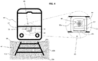
- Fig. 4 is a schematic diagram of a train-mounted alarm system in accordance with an embodiment of the present invention.
- a train 40 is shown on a railway track 41 comprising a first rail 42a and a second rail 42b fixed to a plurality of sleepers 43a...n laid on ballast 44.
- the train-mounted alarm system 45 comprises a highly directional sound generator 46 mounted at the end of the train 40 corresponding to the front of the train 40 based on the direction of travel.
- the highly directional sound generator 46 is adapted to produce a collimated beam 47 of sound parallel to the direction of travel of the train 40, and extends from the train 40 to form the extended protection region, EPR,.
- the highly directional sound generator 46 is further adapted to deliver a minimum sound pressure corresponding to a pre-determined threshold within the collimated beam 47 only. This results in the sound pressure being detectable within the extended protection region EPR only.
- the highly directional sound generator 46 is mounted on a moveable support 48 that enables the highly directional sound generator 46 to be rotated about an axis perpendicular to the train 40 in use.
- the highly directional sound generator 46 is mounted on the train 40 at a height corresponding to the head height of an average-sized person standing on the railway track 41, ensuring that the collimated beam 47 is directed firstly to a region where the sound pressure will have most impact, and secondly at a level below the head height of passengers standing on a platform at a railway station.
- the maximum height of the collimated beam 47 from the railway track is in the range 1.25m to 2.0m.
- the highly directional sound generator 46 comprises a phased array 49 of acoustic emitters 50a...n.
- This may be in the form of the long range acoustic device described above, or a combination of a phased array of ultrasonic acoustic emitters having an audio-frequency within the range of human hearing modulated on top of the acoustic signal.
- This forms a collimated beam of sound parallel to the direction of travel of the train 40.
- an audio-frequency generator 51 is provided, along with the circuitry 52 required to generate the modulated signal.
- the overall result is a collimated beam of sound pressure that is audible by humans.
- Such a beam comprises a central lobe with lobes at harmonics minimised.
- the width W and height H of the extended protection region EPR is determined by the dimensions of the phased array 49 and the signals used to drive the individual ultrasonic acoustic emitters 50a... n.
- the width W may be adjusted by varying which of the individual ultrasonic acoustic emitters 50a... n are turned on across a single row in the phased array 49 at any one time.
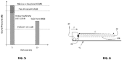
- Fig. 5 is a chart illustrating the requirements of the sound pressure used in embodiments in accordance with the present invention in more detail.
- the x -axis represents distance from a trackside worker in metres and the y -axis is the sound pressure level at that distance in dB.
- the background or ambient noise will be around 50dB to 55dB, and at a distance of 25m from the worker, the horn on a train will sound approximately 88 dB to persons at the crossing.
- the sound pressure level increases to around 105dB to 113dB, which also requires persons to wear hearing protection.
- the pre-determined threshold for sound pressure in this situation is at least 20dB above any ambient noise. Therefore, a minimum sound pressure threshold for persons working with heavy machinery would be at least 120dB. For persons who are not using heavy machinery, whilst they are likely to hear the train horn above the ambient noise depending on the layout of the track this may not always be enough to alert such persons to the imminent danger of the train approach, for example, if the track curves away from the location of such persons. This may give a false impression of how far away the train actually is.
- Fig. 6 is a schematic diagram illustrating the collimated beam generated by embodiments of the present invention in more detail.
- the train 40 travels at a speed 5 along the railway track 41.
- the train mounted alarm system 45 generates an extended protection region EPR that has a length L that is a function of the speed 5 of the train. This is the case whether the train mounted alarm system 45 is adapted to be used continuously whilst the train 40 is travelling at a speed 5 or intermittently whilst the train 40 is travelling at a speed S.
- the length of the extended protection region EPR is preferably a linear function of the speed 5 of the train.
- the length of the extended protection region EPR may be a function of the logarithm of the speed 5 of the train (such as base 10 or a natural logarithm). It may be desirable to have the length of the extended protection region EPR as a linear function of the speed 5 of the train at lower speeds and as a logarithm function of the speed 5 of the train at higher speeds, with the switch between the two occurring at speeds that are typical outside of built up areas. In addition, it may be preferable for the train mounted alarm system to be turned on when the train 40 begins to move from a stationary position. At very low speeds it may be desirable for the length of the extended protection region to be a quadratic function of the speed 5 of the train to ensure that the alarm function is successful.
- the highly directional sound generator 46 is mounted on a movable support 48. This is to enable the collimated beam 47 to be moved whilst the train is in motion, for example, to sweep across the width of the railway track 41 or to anticipate rail track curvature. This allows the collimated beam 47 to effectively push persons or animals across a railway track and out of danger to avoid the sound pressure within the collimated beam.
- the sound pressure within the collimated beam 47 may vary over time, for example, having a lower dB level in regions where there are no crossings or ingress onto the railway track is unlikely or there is no night-time working planned, and a dB level above the pre-determined threshold only where required.
- the highly directional sound generator 46 may comprise more than one audio frequency generator 51 such that sound pressure within the collimated beam 47 is provided with different frequencies. Such frequencies may be tailed to individual issues, such as those most likely to affect humans and those most likely to affect wildlife. It is also possible to adjust the sound pressure output of the collimated beam 47 to create an alarm signature, for example, by using either longer and shorter bursts of sound pressure or bursts of sound pressure at different frequencies.
- the highly directional sound generator may also further comprise a low-frequency signal generator 53 that is used to generate vibrations along the railway track 41 as an additional alarm mechanism. These vibrations may be felt by persons on the track before the collimated beam 47 is audible.
- Such a system comprises a sensor unit, mounted on the train 40, and image processing equipment, preferably within the train in this example. Housing the image processing equipment within the train 40 provides increased security and reduced likelihood of damage from everyday train operation. However, both the sensor unit and the image processing equipment may be fitted to the train 40 together in a single housing, if desired.
- the sensor unit comprises a housing, within which is mounted a LiDAR system.
- the LiDAR system comprises a laser having a wavelength in the infra-red region of the electromagnetic spectrum, a phased array of optical antennas adapted to illuminate at least one region of interest on the railway track 41, a moveable mount adapted to direct the laser in the direction of the railway track 41 ahead of the rail vehicle, and a photodetector connected to the image processing equipment.
- a power source may be provided, or the sensor unit may be linked to a power source on the train.
- the LiDAR system is activated to detect image data received from the railway track 41 when the train 40 is in motion. Image data is received from at least one region of interest on the railway track 41 in order to be able to determine the direction of the railway track 41 ahead, such as the set-direction of a set of points.
- the direction of the LiDAR system may be altered to match that of the upcoming railway track 41 by tilting the moveable base.
- the LiDAR system may have a wide enough field of view to omit the moveable base as all reasonable railway track 41 configurations will sit within that field of view.
- data is received continuously from the LiDAR system, regions of interest are analysed specifically to reduce the on-board computing cost required to implement the overall system.
- the image data is processed to identify the set direction of a set of points in the railway track 41 ahead of the train 40. This set direction may then be used by the train mounted alarm system 45 to alter the direction of the collimated beam 47, in order to ensure the effective generation of the extended protection region EPR.
Landscapes
- Engineering & Computer Science (AREA)
- Mechanical Engineering (AREA)
- Physics & Mathematics (AREA)
- Electromagnetism (AREA)
- General Physics & Mathematics (AREA)
- Train Traffic Observation, Control, And Security (AREA)
- Burglar Alarm Systems (AREA)
Applications Claiming Priority (1)
| Application Number | Priority Date | Filing Date | Title |
|---|---|---|---|
| GB2103662.9A GB2604883A (en) | 2021-03-17 | 2021-03-17 | Moving vehicle warning system |
Publications (2)
| Publication Number | Publication Date |
|---|---|
| EP4059804A2 true EP4059804A2 (de) | 2022-09-21 |
| EP4059804A3 EP4059804A3 (de) | 2022-09-28 |
Family
ID=75623147
Family Applications (1)
| Application Number | Title | Priority Date | Filing Date |
|---|---|---|---|
| EP22162768.0A Pending EP4059804A3 (de) | 2021-03-17 | 2022-03-17 | Warnsystem für ein fahrendes fahrzeug |
Country Status (2)
| Country | Link |
|---|---|
| EP (1) | EP4059804A3 (de) |
| GB (1) | GB2604883A (de) |
Family Cites Families (3)
| Publication number | Priority date | Publication date | Assignee | Title |
|---|---|---|---|---|
| US7106180B1 (en) * | 2001-08-30 | 2006-09-12 | Frank Joseph Pompei | Directional acoustic alerting system |
| US20070102591A1 (en) * | 2005-11-04 | 2007-05-10 | Toth Industries, Llc | Focused Sound Safety Warning System |
| US9102342B2 (en) * | 2012-02-17 | 2015-08-11 | Curtis E. Graber | Locomotive acoustic warning system |
-
2021
- 2021-03-17 GB GB2103662.9A patent/GB2604883A/en not_active Withdrawn
-
2022
- 2022-03-17 EP EP22162768.0A patent/EP4059804A3/de active Pending
Also Published As
| Publication number | Publication date |
|---|---|
| EP4059804A3 (de) | 2022-09-28 |
| GB2604883A (en) | 2022-09-21 |
| GB202103662D0 (en) | 2021-04-28 |
Similar Documents
| Publication | Publication Date | Title |
|---|---|---|
| US12403825B2 (en) | Advanced pedestrian and/or driver alert and/or collision avoidance system | |
| JP7066318B2 (ja) | 車両の外部音合成のためのシステム及び方法 | |
| ES2527613T3 (es) | Métodos y aparatos para detectar y advertir a entidades próximas de interés | |
| US6556148B2 (en) | Emergency flashing light mechanism | |
| US8121755B2 (en) | Sound-directed-outside-vehicle emitting device | |
| US7042345B2 (en) | Intelligent vehicle apparatus and method for using the apparatus | |
| US6580374B2 (en) | Audible communication system | |
| US5973618A (en) | Intelligent walking stick | |
| US7106180B1 (en) | Directional acoustic alerting system | |
| US20040083035A1 (en) | Apparatus and method for automatic vision enhancement in a traffic complex | |
| US9102342B2 (en) | Locomotive acoustic warning system | |
| US12277845B2 (en) | Vehicular incursion alert systems and methods | |
| US11801789B2 (en) | Self-adapting variable loudness and/or variable sound pattern emergency vehicle siren system with optional collision warning | |
| KR101836849B1 (ko) | 초지향성 음원을 이용한 트램 경보유닛 및 이를 포함하는 트램 경보시스템 | |
| US10600318B1 (en) | Blind guiding equipment in pedestrian crosswalk | |
| KR20180106704A (ko) | 보행자와 동물에 대한 차량의 경보 시스템 및 그를 이용한 보행자와 동물에 대한 차량의 경보 방법 | |
| EP4144614A1 (de) | Abschreckung gegen unbefugtes betreten von bahnanlagen | |
| GB2604883A (en) | Moving vehicle warning system | |
| DE102018215010B4 (de) | Kraftfahrzeug mit einer akustischen Warnvorrichtung, und Verfahren zum Betreiben einer akustischen Warnvorrichtung | |
| RU2352490C2 (ru) | Система идентификации автотранспорта и оповещения водителя для предотвращения аварий на железнодорожном переезде | |
| Roos et al. | Feasibility of a directive on-board locomotive audible warning device | |
| CN121799291A (zh) | 车辆的鸣笛控制方法和车辆 |
Legal Events
| Date | Code | Title | Description |
|---|---|---|---|
| PUAI | Public reference made under article 153(3) epc to a published international application that has entered the european phase |
Free format text: ORIGINAL CODE: 0009012 |
|
| STAA | Information on the status of an ep patent application or granted ep patent |
Free format text: STATUS: THE APPLICATION HAS BEEN PUBLISHED |
|
| PUAL | Search report despatched |
Free format text: ORIGINAL CODE: 0009013 |
|
| AK | Designated contracting states |
Kind code of ref document: A2 Designated state(s): AL AT BE BG CH CY CZ DE DK EE ES FI FR GB GR HR HU IE IS IT LI LT LU LV MC MK MT NL NO PL PT RO RS SE SI SK SM TR |
|
| AK | Designated contracting states |
Kind code of ref document: A3 Designated state(s): AL AT BE BG CH CY CZ DE DK EE ES FI FR GB GR HR HU IE IS IT LI LT LU LV MC MK MT NL NO PL PT RO RS SE SI SK SM TR |
|
| RIC1 | Information provided on ipc code assigned before grant |
Ipc: B61L 23/00 20060101AFI20220819BHEP |
|
| STAA | Information on the status of an ep patent application or granted ep patent |
Free format text: STATUS: REQUEST FOR EXAMINATION WAS MADE |
|
| 17P | Request for examination filed |
Effective date: 20230328 |
|
| RBV | Designated contracting states (corrected) |
Designated state(s): AL AT BE BG CH CY CZ DE DK EE ES FI FR GB GR HR HU IE IS IT LI LT LU LV MC MK MT NL NO PL PT RO RS SE SI SK SM TR |
|
| RAP3 | Party data changed (applicant data changed or rights of an application transferred) |
Owner name: SIEMENS MOBILITY LIMITED |
|
| STAA | Information on the status of an ep patent application or granted ep patent |
Free format text: STATUS: EXAMINATION IS IN PROGRESS |
|
| 17Q | First examination report despatched |
Effective date: 20250806 |