EP4059780A1 - Electrical connection box - Google Patents
Electrical connection box Download PDFInfo
- Publication number
- EP4059780A1 EP4059780A1 EP22161870.5A EP22161870A EP4059780A1 EP 4059780 A1 EP4059780 A1 EP 4059780A1 EP 22161870 A EP22161870 A EP 22161870A EP 4059780 A1 EP4059780 A1 EP 4059780A1
- Authority
- EP
- European Patent Office
- Prior art keywords
- connection box
- bus bar
- branch
- box housing
- housing
- Prior art date
- Legal status (The legal status is an assumption and is not a legal conclusion. Google has not performed a legal analysis and makes no representation as to the accuracy of the status listed.)
- Granted
Links
- 239000002184 metal Substances 0.000 claims description 13
- 229910052751 metal Inorganic materials 0.000 claims description 13
- 238000009413 insulation Methods 0.000 claims description 4
- 230000000149 penetrating effect Effects 0.000 description 10
- 239000000463 material Substances 0.000 description 9
- 210000000078 claw Anatomy 0.000 description 5
- 239000004020 conductor Substances 0.000 description 2
- 238000000926 separation method Methods 0.000 description 2
- 229920003002 synthetic resin Polymers 0.000 description 2
- 239000000057 synthetic resin Substances 0.000 description 2
- 239000003990 capacitor Substances 0.000 description 1
- 238000010276 construction Methods 0.000 description 1
- 238000012986 modification Methods 0.000 description 1
- 230000004048 modification Effects 0.000 description 1
- 230000001012 protector Effects 0.000 description 1
Images


Classifications
-
- B—PERFORMING OPERATIONS; TRANSPORTING
- B60—VEHICLES IN GENERAL
- B60R—VEHICLES, VEHICLE FITTINGS, OR VEHICLE PARTS, NOT OTHERWISE PROVIDED FOR
- B60R16/00—Electric or fluid circuits specially adapted for vehicles and not otherwise provided for; Arrangement of elements of electric or fluid circuits specially adapted for vehicles and not otherwise provided for
- B60R16/02—Electric or fluid circuits specially adapted for vehicles and not otherwise provided for; Arrangement of elements of electric or fluid circuits specially adapted for vehicles and not otherwise provided for electric constitutive elements
- B60R16/023—Electric or fluid circuits specially adapted for vehicles and not otherwise provided for; Arrangement of elements of electric or fluid circuits specially adapted for vehicles and not otherwise provided for electric constitutive elements for transmission of signals between vehicle parts or subsystems
- B60R16/0238—Electrical distribution centers
-
- H—ELECTRICITY
- H02—GENERATION; CONVERSION OR DISTRIBUTION OF ELECTRIC POWER
- H02G—INSTALLATION OF ELECTRIC CABLES OR LINES, OR OF COMBINED OPTICAL AND ELECTRIC CABLES OR LINES
- H02G3/00—Installations of electric cables or lines or protective tubing therefor in or on buildings, equivalent structures or vehicles
- H02G3/02—Details
- H02G3/08—Distribution boxes; Connection or junction boxes
- H02G3/086—Assembled boxes
-
- B—PERFORMING OPERATIONS; TRANSPORTING
- B60—VEHICLES IN GENERAL
- B60R—VEHICLES, VEHICLE FITTINGS, OR VEHICLE PARTS, NOT OTHERWISE PROVIDED FOR
- B60R16/00—Electric or fluid circuits specially adapted for vehicles and not otherwise provided for; Arrangement of elements of electric or fluid circuits specially adapted for vehicles and not otherwise provided for
- B60R16/02—Electric or fluid circuits specially adapted for vehicles and not otherwise provided for; Arrangement of elements of electric or fluid circuits specially adapted for vehicles and not otherwise provided for electric constitutive elements
- B60R16/023—Electric or fluid circuits specially adapted for vehicles and not otherwise provided for; Arrangement of elements of electric or fluid circuits specially adapted for vehicles and not otherwise provided for electric constitutive elements for transmission of signals between vehicle parts or subsystems
- B60R16/0239—Electronic boxes
-
- H—ELECTRICITY
- H01—ELECTRIC ELEMENTS
- H01R—ELECTRICALLY-CONDUCTIVE CONNECTIONS; STRUCTURAL ASSOCIATIONS OF A PLURALITY OF MUTUALLY-INSULATED ELECTRICAL CONNECTING ELEMENTS; COUPLING DEVICES; CURRENT COLLECTORS
- H01R25/00—Coupling parts adapted for simultaneous co-operation with two or more identical counterparts, e.g. for distributing energy to two or more circuits
- H01R25/14—Rails or bus-bars constructed so that the counterparts can be connected thereto at any point along their length
-
- H—ELECTRICITY
- H02—GENERATION; CONVERSION OR DISTRIBUTION OF ELECTRIC POWER
- H02G—INSTALLATION OF ELECTRIC CABLES OR LINES, OR OF COMBINED OPTICAL AND ELECTRIC CABLES OR LINES
- H02G3/00—Installations of electric cables or lines or protective tubing therefor in or on buildings, equivalent structures or vehicles
- H02G3/02—Details
- H02G3/08—Distribution boxes; Connection or junction boxes
- H02G3/081—Bases, casings or covers
-
- H—ELECTRICITY
- H02—GENERATION; CONVERSION OR DISTRIBUTION OF ELECTRIC POWER
- H02G—INSTALLATION OF ELECTRIC CABLES OR LINES, OR OF COMBINED OPTICAL AND ELECTRIC CABLES OR LINES
- H02G3/00—Installations of electric cables or lines or protective tubing therefor in or on buildings, equivalent structures or vehicles
- H02G3/02—Details
- H02G3/08—Distribution boxes; Connection or junction boxes
- H02G3/16—Distribution boxes; Connection or junction boxes structurally associated with support for line-connecting terminals within the box
-
- H—ELECTRICITY
- H05—ELECTRIC TECHNIQUES NOT OTHERWISE PROVIDED FOR
- H05K—PRINTED CIRCUITS; CASINGS OR CONSTRUCTIONAL DETAILS OF ELECTRIC APPARATUS; MANUFACTURE OF ASSEMBLAGES OF ELECTRICAL COMPONENTS
- H05K7/00—Constructional details common to different types of electric apparatus
- H05K7/02—Arrangements of circuit components or wiring on supporting structure
- H05K7/026—Multiple connections subassemblies
Definitions
- the present invention relates to an electrical connection box.
- Some electrical connection boxes include a first bus bar located in the upper side in the vertical direction, a second bus bar located in the lower side in the vertical direction, and an electronic component (fusible link) that electrically connects the first bus bar and the second bus bar (see, e.g., Japanese Patent Application Laid-open No. 2016-103927 ).
- connection box housing that stores a connection box bus bar therein and a storing box housing that stores a branch box bus bar therein.
- connection box in the case where the connection box housing and the branch box housing are stacked in the vertical direction and the connection box bus bar and the storing box bus bar are electrically connected by an electronic component, works for the connection are time-consuming as described below.
- the electrical connection between the connection box bus bar and the electronic component and then between the storing box bus bar and the electronic component allows the connection box bus bar and the storing box bus bar to be electrically connected through the electronic component.
- the present invention is made in view of the circumstances described above and provides an electrical connection box having two bus bars, which is capable of facilitating an electrical connection work between one bus bar and the other bus bar.
- an electrical connection box includes a connection box housing having an insulation property configured to store a connection box bus bar having conductivity inside the connection box housing; and a branch box housing having an insulation property configured to store a branch box bus bar having conductivity inside the branch box housing; wherein the branch box housing and the connection box housing are stacked in a vertical direction, and the connection box bus bar and the branch box bus bar are electrically connected by bringing a connection box bus bar tip portion of the connection box bus bar into direct contact with a branch box bus bar tip portion of the branch box bus bar and by jointly fastening the tip portions using a bus bar fastening member in a state in which the connection box bus bar tip portion is in direct contact with the branch box bus bar tip portion.
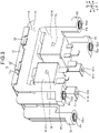
- FIG. 1 is a perspective view of an electrical connection box 1 according to the present embodiment.
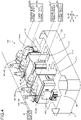
- FIG. 2 is an exploded perspective view of the electrical connection box 1 according to the present embodiment.
- FIG. 3 is a perspective view of a branch box housing 5 included in the electrical connection box 1 according to the present embodiment.
- FIG. 4 is a perspective view illustrating the inside of the branch box housing 5 according to the present embodiment.
- FIG. 5 is a perspective view illustrating a connection box bus bar 3 and a branch box bus bar 6 according to the present embodiment.
- FIG. 6 is a cross-sectional view illustrating a leg portion of the branch box housing 5 and a contact portion of a connection box housing 2, which is in contact with the leg portion , in the electrical connection box 1 according to the present embodiment.
- FIG. 7 is a plan view of the connection box housing 2 of the electrical connection box according to the present embodiment.
- FIG. 8 is a bottom view of the branch box housing 5 of the electrical connection box according to the present embodiment.
- Z represents the vertical direction of the electrical connection box 1
- X represents a first orthogonal direction orthogonal to the vertical direction Z in the electrical connection box 1
- Y represents a second orthogonal direction orthogonal to the vertical direction Z and the first orthogonal direction X in the electrical connection box 1.
- the first orthogonal direction X, the second orthogonal direction Y, and the vertical direction Z are orthogonal to each other.
- the electrical connection box 1 is installed in a vehicle such as an automobile and incorporated into a wire harness WH1.
- the wire harness WH1 is, for example, used for connection with respective electronic devices D (see FIG. 4 ) installed in a vehicle.
- the wire harness WH1 is an assembled part in which a plurality of wiring materials W for the power supply or signal communication is bundled and is used for connecting the plurality of wiring materials W to the respective electronic devices D using a connector or the like.
- the wire harness WH1 includes the conductive wiring material W and the electrical connection box 1 that is electrically connected to the wiring material W.
- the wiring material W includes, for example, a metal rod, an electric wire, an electric wire bundle, or the like.
- the metal rod includes a conductive rod-shaped member having an outer side covered with an insulating covering portion.
- the electric wire includes a conductor portion (core wire) having an outer side covered with an insulating covering portion, and the conductor portion is made of a plurality of conductive metal strands.
- the electric wire bundle is a bundle of electric wires.
- the plurality of wiring materials W is bundled and tied, and the electrical connection box 1 is electrically connected to the wire harness through a connector or the like provided at the end portion of the bundled wiring materials W.
- the wire harness WH1 can further include a grommet, a protector, an exterior material, a fixture, and the like.
- the electrical connection box 1 is an assembled part of electrical components such as connectors, fuses, relays, capacitors, branch portions, and electronic control units, which are stored therein.
- the electrical connection box 1 is installed in, for example, the engine room or the interior of a vehicle.
- the electrical connection box 1 is connected between a power supply P such as a battery or a generator and various electronic devices D attached to the inside of the vehicle through a power supply line W1 and an electric wire W2 included in the wiring material W, as illustrated in FIG. 4 .
- the electrical connection box 1 distributes the electric power supplied from the power supply P to the various electronic devices D in the vehicle.
- the electrical connection box 1 uses a first electronic device D1 described later to distribute the electric power supplied from the power supply P to the first electronic device D1 and a second electronic device D2.
- the electrical connection box 1 uses the second electronic device D2 described later to distribute the electric power supplied from the power supply P to a third electronic device D3 and a fourth electronic device D4.
- the electrical connection box 1 is also referred to as a junction box, a fuse box, a relay box, or the like in some cases, but in the present embodiment, these are collectively referred to as the electrical connection box 1.
- the configuration of the electrical connection box 1 is now described in detail with reference to each drawing.
- the electrical connection box 1 includes an insulating connection box housing 2 and an insulating branch box housing 5.
- the insulating connection box housing 2 has a connection box storing space 2s therein
- the insulating branch box housing 5 has a branch box storing space 5s therein.
- the electrical connection box 1 is provided with a fixing mechanism 7, which is provided between the connection box housing 2 and the branch box housing 5 and directly fixes the branch box housing 5 to the connection box housing 2 (see FIGS. 7 and 8 ).
- connection box housing 2 includes a plurality of conductive connection box bus bars 3 illustrated in FIG. 5 in the connection box storing space 2s.
- the electrical connection box 1 includes the insulating connection box housing 2 that stores the conductive connection box bus bar 3 therein.
- connection box housing 2 has the connection box housing body 21, which forms the connection box storing space 2s, and a connection box housing bottom portion 22 as illustrated in FIGS. 1 and 2 .
- the connection box housing body 21 has, as illustrated in FIG. 7 , a pair of first connection box housing-facing walls 21a, a pair of second connection box housing-facing walls 21b, and a connection box housing top portion 21c.
- the pair of first connection box housing-facing walls 21a faces each other in the first orthogonal direction X.
- the pair of second connection box housing-facing walls 21b faces each other in the second orthogonal direction Y.
- the connection box housing top portion 21c faces the connection box housing bottom portion 22 in the vertical direction Z.
- connection box housing top portion 21c is located above the connection box housing 2 in the vertical direction Z. Then, the connection box housing top portion 21c is provided with first and second connectors 36 and 37 and two top through-holes 21ch. The first connector 36 and the second connector 37 are provided on the connection box housing top portion 21c while being exposed to the outside in a state where the branch box housing 5 is attached to the connection box housing 2. Each of the top through-holes 21ch penetrates the connection box housing top portion 21c in the vertical direction Z, communicating the connection box storing space 2s with the outside.
- the connection box housing bottom portion 22 is provided with two bottom through-holes 22ch. Each bottom through-hole 22ch penetrates the connection box housing bottom portion 22 in the vertical direction Z, communicating the connection box storing space 2s with the outside.
- a screw portion 811 of a first bolt 81a described later is inserted through one bottom through-hole 22ch.
- a screw portion 821 of a second bolt 82a described later is inserted through another bottom through-hole 22ch.
- connection box housing 2 has a connection box housing contact portion (contact parts) 21d at every four corners of the connection box housing body 21 in the horizontal plane including the first orthogonal direction X and the second orthogonal direction Y.
- the connection box housing contact portion 21d is in direct contact with each of branch box housing leg portions 53 described below.
- connection box housing contact portion 21d has a contact portion through-hole 21dh that penetrates the connection box housing contact portion 21d in the vertical direction Z as illustrated in FIG. 7 . Then, the connection box housing contact portion 21d is provided with a second metal collar 21dc. More specifically, the connection box housing contact portion 21d is provided with the second collar 21dc that fits into the contact portion through-hole 21dh. The second collar 21dc has a second collar through-hole 21dch that penetrates the second collar 21dc in the vertical direction.
- a screw portion 831 of a third bolt 83a in a fixed fastening member 83 is inserted through the contact portion through-hole 21dh and the second collar through-hole 21dch and the screw portion 831 is screwed into a screw hole 83b that is formed in a plate portion 101 of a vehicle, thereby attaching the electrical connection box 1 to the plate portion of the vehicle.
- the fixed fastening member 83 according to the present embodiment includes a screw hole 83bh formed in the plate portion 101 of the vehicle and a third bolt 83a.
- the plate portion 101 in which the screw hole 83bh is formed serves as an attached portion to which the electrical connection box 1 is attached in the vehicle.
- connection box bus bar 3 includes a first connection box bus bar 31, a second connection box bus bar 32, a third connection box bus bar 33, and a fourth connection box bus bar 34, as illustrated in FIG. 5 .
- connection box housing according to the present embodiment includes a plurality of electronic components 4 so that a part of each of the electronic components 4 is exposed from above, as illustrated in FIG. 4 .
- the electronic component 4 according to the present embodiment includes a first electronic component 41 and a second electronic component 42.
- the first connection box bus bar 31 has a tip portion 31a electrically connected to the first connector 36 (see FIG. 4 ).
- the first connector 36 is attachable or detachable to or from a first terminal W1a provided at the end of the power supply line W1 connected to the power supply P as illustrated in FIG. 4 .
- the first connection box bus bar 31 has another tip portion 31b electrically connected to the first electronic component 41, as illustrated in FIG. 5 .
- the second connection box bus bar 32 has a tip portion 32a electrically connected to the first electronic component 41.
- Another tip portion of the second connection box bus bar 32 (hereinafter, referred to as “the second connection box bus bar tip portion 32b") includes a though-hole penetrating the second connection box bus bar tip portion 32b in the vertical direction Z.
- the second connection box bus bar tip portion 32b is brought into direct contact with the other tip portion of the first branch box bus bar 61 (hereinafter, referred to as "the first branch box bus bar tip portion 61b").
- the first branch box bus bar tip portion 61b has a through-hole 61bh penetrating the first branch box bus bar tip portion 61b in the vertical direction Z (see FIG. 3 ).
- the screw portion 811 of the first bolt 81a in a first bus bar fastening member 81 is inserted into a through-hole of the second connection box bus bar tip portion 32b and a through-hole 61bh of the first branch box bus bar tip portion 61b so that the second connection box bus bar tip portion 32b and the first branch box bus bar tip portion 61b are brought into direct contact with each other.
- screwing the screw portion 811 of the first bolt 81a into a screw hole 812 of a first nut 81b fastens the second connection box bus bar tip portion 32b to the first branch box bus bar tip portion 61b together using the first bus bar fastening member 81.
- the second connection box bus bar 32 and the first branch box bus bar 61 are electrically connected by bringing the second connection box bus bar tip portion 32b of the second connection box bus bar 32 into direct contact with the first branch box bus bar tip portion 61b of the first branch box bus bar 61 and by jointly fastening the tip portions using the first bus bar fastening member 81 in the state where the second connection box bus bar tip portion 32b is in direct contact with the first branch box bus bar tip portion 61b.
- the first bus bar fastening member 81 includes the first bolt 81a and the first nut 81b.
- the first nut 81b has the screw hole 812 screwed into the screw portion 811 of the first bolt 81a.
- the third connection box bus bar 33 has a tip portion 33a electrically connected to the second electronic component 42.
- Another tip portion of the third connection box bus bar 33 (hereinafter, referred to as “the third connection box bus bar tip portion 33b") includes a though-hole penetrating the third connection box bus bar tip portion 33b in the vertical direction Z.
- the third connection box bus bar tip portion 33b is brought into direct contact with the other tip portion of the second branch box bus bar 62 (hereinafter, referred to as "the second branch box bus bar tip portion 62b").
- the second branch box bus bar tip portion 62b has a through-hole 62bh penetrating the second branch box bus bar tip portion 62b in the vertical direction Z (see FIG. 3 ).
- the screw portion 821 of the second bolt 82a in a second bus bar fastening member 82 is inserted into a through-hole of the third connection box bus bar tip portion 33b and a through-hole 62bh of the second branch box bus bar tip portion 62b so that the third connection box bus bar tip portion 33b and the second branch box bus bar tip portion 62b are brought into direct contact with each other.
- screwing the screw portion 821 of the second bolt 82a into a screw hole 822 of a second nut 82b fastens the third connection box bus bar tip portion 33b to the second branch box bus bar tip portion 62b together using the second bus bar fastening member 82.
- the third connection box bus bar 33 and the second branch box bus bar 62 are electrically connected by bringing the third connection box bus bar tip portion 33b of the third connection box bus bar 33 into direct contact with the second branch box bus bar tip portion 62b of the second branch box bus bar 62 and by jointly fastening the tip portions using the second bus bar fastening member 82 in the state where the third connection box bus bar tip portion 33b is in direct contact with the second branch box bus bar tip portion 62b.
- the second bus bar fastening member 82 includes the second bolt 82a and the second nut 82b.
- the second nut 82b has the screw hole 822 screwed into the screw portion 821 of the second bolt 82a.
- the fourth connection box bus bar 34 has a tip portion 34a electrically connected to the second connector 37 (see FIG. 4 ).
- the second connector 37 is attachable or detachable to or from a second terminal W1b provided at the end of the power supply line W1 connected to the power supply P as illustrated in FIG. 4 .
- the fourth connection box bus bar 34 has another tip portion 34b electrically connected to the second electronic component 42, as illustrated in FIG. 5 .
- the first electronic component 41 and the second electronic component 42 are, for example, relays. More specifically, the first electronic component 41 distributes the electric power supplied from the power supply P to the first electronic device D1 and the second electronic device D2 as necessary. In addition, the second electronic component 42 distributes the electric power supplied from the power supply P to the third electronic device D3 and the fourth electronic device D4 as necessary.
- connection box housing body 21 and each electronic component 4 are provided with a locking mechanism 74 that locks each electronic component 4 to the connection box housing body 21.
- the locking mechanism 74 includes, for example, a locking claw 75 and a locking hole portion 76.
- the locking claw 75 is provided in the electronic component 4.
- the locking hole portion 76 is provided in the connection box housing body and is engageable with the locking claw 75.
- the branch box housing 5 includes a plurality of conductive branch box bus bars 6 in the branch box storing space 5s illustrated in FIG. 3 (see FIG. 5 ).
- the electrical connection box 1 includes the insulating branch box housing 5 that stores the conductive branch box bus bar 6 therein.
- the branch box housing 5 has a branch box housing body 51, which forms the branch box storing space 5s therein, and a branch box housing lid 52, as illustrated in FIG. 2 .
- the branch box housing body 51 has, as illustrated in FIG. 8 , a pair of first branch box housing-facing walls 51a, a pair of second branch box housing-facing walls 51b, and a branch box housing bottom portion 51c.
- the pair of first branch box housing-facing walls 51a faces each other in the first orthogonal direction X.
- the pair of second branch box housing-facing walls 51b faces each other in the second orthogonal direction Y.
- the branch box housing bottom portion 51c faces the branch box housing lid 52 at the fully closed position in the vertical direction Z
- One first branch box housing-facing wall 51a of the pair of first branch box housing-facing walls 51a is provided with two first facing wall through-holes. Each first facing wall portion through-hole penetrates the first branch box housing-facing wall 51a in the second orthogonal direction Y to communicate the branch box storing space 5s with the outside.
- the electrical connection box 1 is provided with the rotation support mechanism 9 that supports in such a manner that the branch box housing lid 52 is rotated around a rotation shaft 9x with respect to the branch box housing body 51 between the branch box housing body 51 and the branch box housing lid 52 as illustrated in FIG. 1 .
- the rotation support mechanism 9 includes a cylindrical portion 91 and a support receiving portion 92.
- the cylindrical portion 91 is provided on the branch box housing lid 52, and the support receiving portion 92 is provided on the branch box housing body 51 and supports in such a manner that the cylindrical portion 91 is rotated around the rotation shaft 9x.
- the rotation support mechanism 9 according to the present embodiment is, for example, a hinge.
- the branch box bus bar 6 is exposed to the outside in the state where the branch box housing lid 52 opens with respect to the branch box housing body 51.
- the branch box bus bar 6 closes inside the branch box storing space 5s in the state where the branch box housing lid 52 closes with respect to the branch box housing body 51.
- the branch box housing 5 has the branch box housing leg portion (leg parts) 53 extending from the upper side to the lower side of the branch box housing body 51 in the vertical direction Z as illustrated in FIG. 3 .
- the branch box housing 5 according to the present embodiment has the branch box housing leg portion 53 at every four corners of the branch box housing body 51 in a horizontal plane including the first orthogonal direction X and the second orthogonal direction Y as illustrated in FIG. 8 .
- Each branch box housing leg portion 53 is provided with a first metal collar 53c.
- the branch box bus bar 6 includes the first branch box bus bar 61 and the second branch box bus bar 62 as illustrated in FIG. 5 .
- the first branch box bus bar 61 has one tip portion 61a with a through-hole penetrating the tip portion 61a in the vertical direction Z. Then, the tip portion is brought into direct contact with an electric wire terminal W2a provided at one end of the electric wire W2 described above. Each electric wire terminal W2a has a terminal through-hole W2ah penetrating the terminal W2a in the vertical direction Z. Then, a screw portion 841 of a fourth bolt 84a in an electric wire fastening member 84 is inserted into the through-hole of the tip portion 61a and the terminal through-hole W2ah, and so the tip portion 61a of the first branch box bus bar 61 and the wire terminal W2a are brought into direct contact with each other.
- the first branch box bus bar tip portion 61b of the first branch box bus bar 61 has a through-hole 61bh penetrating the first branch box bus bar tip portion 61b in the vertical direction Z (see FIG. 3 ). Then, the first branch box bus bar tip portion 61b and the second connection box bus bar tip portion 32b are electrically connected by fastening them together using the first bus bar fastening member 81 in a state where they are brought into direct contact with each other.
- the tip portion 61a of the first branch box bus bar 61 is located inside the branch box storing space 5s.
- the first branch box bus bar 61 is inserted through one of the first facing wall portion through-holes, and so a part of the first branch box bus bar 61 is located outside.
- the first branch box bus bar 61 is inserted through one of the top through-holes 21ch, and so the first branch box bus bar tip portion 61b is located inside the connection box storing space 2s.
- a part of the first branch box bus bar 61 is exposed to the outside, but in the part exposed to the outside, another device is arranged adjacent to the electrical connection box 1 in the vehicle, so the operator does not touch the part of the first branch box bus bar 61 exposed to the outside.
- the second branch box bus bar 62 has one tip portion 62a with a through-hole penetrating the tip portion 62a in the vertical direction Z. Then, the tip portion is brought into direct contact with an electric wire terminal W2a provided at one end of the electric wire W2 described above. Each electric wire terminal W2a has a terminal through-hole W2ah penetrating the terminal W2a in the vertical direction Z. Then, a screw portion 841 of a fourth bolt 84a in an electric wire fastening member 84 is inserted into the through-hole of the tip portion 62a and the terminal through-hole W2ah, and so the tip portion 62a of the second branch box bus bar 62 and the wire terminal W2a are brought into direct contact with each other.
- the second branch box bus bar tip portion 62b of the second branch box bus bar 62 has a through-hole 62bh penetrating the second branch box bus bar tip portion 62b in the vertical direction Z (see FIG. 3 ). Then, the second branch box bus bar tip portion 62b and the third connection box bus bar tip portion 33b are electrically connected by fastening them together using the second bus bar fastening member 82 in a state where they are brought into direct contact with each other.
- the tip portion 62a of the second branch box bus bar 62 is located inside the branch box storing space 5s.
- the second branch box bus bar 62 is inserted through the other first facing wall portion through-hole, and so a part of the second branch box bus bar 62 is located outside.
- the second branch box bus bar 62 is inserted through the other top through-hole 21ch, and so the second branch box bus bar tip portion 62b is located inside the connection box storing space 2s.
- a part of the second branch box bus bar 62 is exposed to the outside, but in the part exposed to the outside, another device is arranged adjacent to the electrical connection box 1 in the vehicle, so the operator does not touch the part of the second branch box bus bar 62 exposed to the outside.
- the electrical connection between the components as described above enables the power supply P and the first electronic device D1 to be electrically connected and the power supply P and the second electronic device D2 to be electrically connected in the state where the first electronic component 41 is interposed. Then, in the electrical connection box 1, the first electronic device D1 or the second electronic device D2 is supplied with the electric power from the power supply P by turning on a switch of the first electronic component 41 on the basis of a command from the ECU provided in the vehicle. In addition, in the electrical connection box 1, the power supply from the power supply P to the first electronic device D1 or the second electronic device D2 is cut off by turning off the switch of the first electronic component 41 on the basis of the command from the ECU provided in the vehicle.
- the electrical connection between the components as described above enables the power supply P and the third electronic device D3 to be electrically connected and the power supply P and the fourth electronic device D4 to be electrically connected in the state where the second electronic component 42 is interposed. Then, in the electrical connection box 1, the third electronic device D3 or the fourth electronic device D4 is supplied with the electric power from the power supply P by turning on a switch of the second electronic component 42 on the basis of a command from the ECU provided in the vehicle. In addition, in the electrical connection box 1, the power supply from the power supply P to the third electronic device D3 or the fourth electronic device D4 is cut off by turning off the switch of the second electronic component 42 on the basis of the command from the ECU provided in the vehicle.
- the fixing mechanism 7 has a rib 71 provided on the branch box housing 5 and a press-fitted portion 72 to which the rib 71 provided on the connection box housing 2 is allowed to be press-fitted.
- the electrical connection box 1 according to the present embodiment has one fixing mechanism 7.
- the rib 71 is located between two branch box housing leg portion 53 when viewed from one side of the first orthogonal direction X and is located between two branch box housing leg portions 53 when viewed from one side of the second orthogonal direction Y, as illustrated in FIG. 8 .
- the press-fitted portion 72 is located between two connection box housing contact portions 21d when viewed from one side of the first orthogonal direction X and is located between two connection box housing contact portions 21d when viewed from one side of the second orthogonal direction Y, as illustrated in FIG. 7 .
- the rib 71 extends downward from the lower surface of the branch box housing bottom portion 51c in the vertical direction as illustrated in FIG. 8 .
- the rib 71 has a first linear portion 71a extending in the first orthogonal direction X and a second linear portion 71b extending in the second orthogonal direction Y when viewed from below in the vertical direction.
- the rib 71 is formed in a cross shape in which the center in the first linear portion 71a in the first orthogonal direction intersects the center in the second linear portion 71b in the second orthogonal direction Y When viewed from below in the vertical direction.
- the press-fitted portion 72 extends upward from the upper surface of the connection box housing top portion 21c in the vertical direction as illustrated in FIGS. 2 and 7 .
- the press-fitted portion 72 has a first portion 72a located on one side in the second orthogonal direction Y and a second portion 72b located on the other side in the second orthogonal direction when viewed from above in the vertical direction.
- a press-fitting space portion 72s that press-fits the rib 71 is formed between the first portion 72a and the second portion 72b.
- the first portion 72a includes a first linear portion extending in the second orthogonal direction Y and a pair of second protrusions that protrude from both ends of the first linear portion in a direction close to the second portion 72b, and so forms a C shape. Then, in the first portion 72a, a first space is formed between a pair of first protrusions in the second orthogonal direction Y.
- the second portion 72b includes a second linear portion extending in the second orthogonal direction Y and a pair of second protrusions that protrude from both ends of the second linear portion in a direction close to the first portion 72a, and so forms a C shape. Then, in the second portion 72b, a second space is formed between a pair of second protrusions in the second orthogonal direction Y.
- the separation interval between the first portion 72a and the second portion 72b in the first orthogonal direction X in the non-press-fitted state in which the rib 71 and the press-fitted portion 72 are separated in the vertical direction Z is larger than the separation interval between the first portion 72a and the second portion 72b in the state where the rib 71 is press-fitted into the press-fitted portion 72.
- the fixing mechanism 7 according to the present embodiment in which the rib 71 is provided on the branch box housing 5 and the press-fitted portion 72 is provided on the connection box housing 2.
- the fixing mechanism 7 according to the present embodiment is not limited to this exemplary configuration.
- the press-fitted portion 72 may be provided on the branch box housing 5, and the rib 71 may be provided on the connection box housing 2.
- the fixing mechanism 7 according to the present embodiment has the rib 71 and the press-fitted portion 72.
- the rib 71 is provided on one housing of the connection box housing 2 and the branch box housing 5, and the press-fitted portion 72 to which the rib 71 provided on the other housing is allowed to be press-fitted.
- connection box housing 2 The assembly of the electrical connection box 1 according to the present embodiment is now described.
- the operator first fixes the connection box housing 2 at a predetermined position and then arranges the branch box housing 5 above the connection box housing 2 in the vertical direction Z.
- the operator matches the position of the press-fitted portion 72 in the first orthogonal direction X and the second orthogonal direction Y with the position of the rib 71 in the first orthogonal direction X and the second orthogonal direction Y.
- the operator shifts the branch box housing 5 from the upper side to the lower side in the vertical direction Z to press-fit the rib 71 into the press-fitted portion 72.
- the electrical connection box 1 is capable of matching the positions of the connection box bus bar tip portions 32b and 33b with the positions of the branch box bus bar tip portions 61b and 62b. In addition, in the state where the rib 71 is press-fitted into the press-fitted portion 72, the electrical connection box 1 is capable of matching the position of the connection box housing contact portion 21d with the position of the branch box housing leg portion 53.
- the operator fastens the second connection box bus bar tip portion 32b and the first branch box bus bar tip portion 61b using the first bus bar fastening member 81.
- the operator fastens the third connection box bus bar tip portion 33b and the second branch box bus bar tip portion 62b using the second bus bar fastening member 82.
- connection box housing contact portion 21d and the branch box housing leg portion 53 using the fixed fastening member 83 and arranges the branch box housing 5 above the connection box housing 2 in the vertical direction Z.
- the operator fixes the electrical connection box 1 to the plate portion 101 that is the attached portion of the vehicle.
- the electrical connection box 1 has the following configuration.
- the connection box bus bar 3 and the branch box bus bar 6 are electrically connected by bringing the connection box bus bar tip portions 32b and 33b of the connection box bus bar 3 into direct contact with the branch box bus bar tip portions 61b and 62b of the branch box bus bar 6 and by jointly fastening the tip portions using the bus bar fastening members 81 and 82 in the state where the connection box bus bar tip portions 32b and 33b are in direct contact with the branch box bus bar tip portions 61b and 62b.
- the electrical connection box 1 eliminates the need to provide an electronic component or an intermediate bus bar that electrically connects the connection box bus bar 3 with the branch box bus bar 6.
- the electrical connection box 1 it is possible for the electrical connection box 1 to eliminate the work of electrically connecting the connection box bus bar 3, the intermediate bus bar, or the like, and to eliminate the work of electrically connecting the branch box bus bar 6, the intermediate bus bar, or the like. Accordingly, the electrical connection box 1 according to the present embodiment is capable of facilitating the electrical connection work between the connection box bus bar 3 and the branch box bus bar 6.
- the electrical connection box 1 according to the present embodiment has the following configuration.
- the connection box housing 2 and the branch box housing 5 are fixed to the vehicle by jointly fastening the leg portion 53 and the contact portion 21d using the fixed fastening member 83 in the state where the leg portion 53 and the contact portion 21d are in direct contact with the plate portion 101 that is the attached portion provided on the vehicle.
- the electrical connection box 1 according to the present embodiment eliminates the need to separately perform the work of fixing the connection box housing 2 to the attached portion of the vehicle and the work of fixing the branch box housing 5 to the attached portion of the vehicle. Accordingly, according to the present embodiment, it is possible to facilitate the work to fix the electrical connection box 1 to the vehicle.
- the electrical connection box 1 according to the present embodiment has the following configuration.
- the fixing mechanism 7 used to directly fix the branch box housing 5 to the connection box housing 2 is provided between the connection box housing 2 and the branch box housing 5.
- the fixing mechanism 7 has the rib 71 provided on one housing of the connection box housing 2 and the branch box housing 5 and the press-fitted portion 72 to which the rib 71 provided on the other housing is allowed to be press-fitted.
- the electrical connection box 1 according to the present embodiment makes it possible to directly fix the branch box housing 5 and the connection box housing 2 to each other using the fixing mechanism 7. Accordingly, the electrical connection box 1 according to the present embodiment is capable of fixing the branch box housing 5 the connection box housing 2 with reliability.
- the electrical connection box 1 has the following configuration.
- the leg portion 53 is provided with a first metal collar 53c
- the contact portion 21d is provided with the second metal collar 21dc
- the fixed fastening member 83 is made of metal.
- connection box housing 2 is arranged below in the vertical direction Z, while the branch box housing 5 is arranged above the connection box housing 2 in the vertical direction Z.
- the electrical connection box 1 according to the present embodiment is not limited to this exemplary configuration, and the branch box housing 5 may be arranged below in the vertical direction Z, while the connection box housing 2 may be arranged above the branch box housing 5 in the vertical direction Z.
- the electrical connection box 1 which stores a part of the electronic component 4 inside the connection box housing 2 and a part of the electronic component 4 inside the branch box housing 5.
- the electrical connection box 1 according to the present embodiment is not limited to this exemplary configuration. Specifically, the entire electronic component 4 may be stored inside the connection box housing 2, and the electronic component 4 may not be stored inside the branch box housing 5.
- the electrical connection box 1 which stores the entire electronic component 4 inside the connection box housing 2 and does not store the electronic component 4 inside the branch box housing 5.
- the electrical connection box 1 according to the present embodiment is not limited to this exemplary configuration.
- the electrical connection box 1 may store the entire electronic component 4 inside the branch box housing 5, and the electronic component 4 may not be stored inside the connection box housing 2.
- the electrical connection box 1 may store the entire electronic component 4 inside the connection box housing 2 and may store other electronic components 4 different from the electronic component 4 inside the branch box housing 5.
- the locking mechanism 74 according to the embodiment having the locking claw 75 provided in the electronic component 4 and the locking hole portion 76 provided in the connection box housing body 21.
- the locking mechanism 74 according to the present embodiment is not limited to this exemplary configuration, and the locking claw 75 may be provided in the connection box housing body 21, while the locking hole portion 76 may be provided in the electronic component 4.
- the shape of the rib 71 of the fixing mechanism 7 and the shape of the press-fitted portion 72 are not limited to those described above, and can be modified as appropriate.
- the branch box housing body 51 is provided with the cylindrical portion 91, while the branch box housing lid 52 is provided with the support receiving portion 92.
- the rotation support mechanism 9 according to the present embodiment is not limited to this exemplary configuration.
- the branch box housing body 51 may be provided with the support receiving portion 92, while the branch box housing lid 52 may be provided with the cylindrical portion 91.
- the electrical connection box having the configuration described above is capable of facilitating the electrical connection work between the connection box bus bar and the branch box bus bar.
Abstract
Description
- The present invention relates to an electrical connection box.
- Some electrical connection boxes include a first bus bar located in the upper side in the vertical direction, a second bus bar located in the lower side in the vertical direction, and an electronic component (fusible link) that electrically connects the first bus bar and the second bus bar (see, e.g.,
Japanese Patent Application Laid-open No. 2016-103927 - Further, some electrical connection boxes are provided with a connection box housing that stores a connection box bus bar therein and a storing box housing that stores a branch box bus bar therein.
- In the electrical connection box described above, in the case where the connection box housing and the branch box housing are stacked in the vertical direction and the connection box bus bar and the storing box bus bar are electrically connected by an electronic component, works for the connection are time-consuming as described below. In other words, the electrical connection between the connection box bus bar and the electronic component and then between the storing box bus bar and the electronic component allows the connection box bus bar and the storing box bus bar to be electrically connected through the electronic component. Thus, in the electrical connection box described above, there is room to improve the facilitation of the electrical connection work of the bus bars.
- The present invention is made in view of the circumstances described above and provides an electrical connection box having two bus bars, which is capable of facilitating an electrical connection work between one bus bar and the other bus bar.
- To achieve the above object, an electrical connection box according to one aspect of the present invention includes a connection box housing having an insulation property configured to store a connection box bus bar having conductivity inside the connection box housing; and a branch box housing having an insulation property configured to store a branch box bus bar having conductivity inside the branch box housing; wherein the branch box housing and the connection box housing are stacked in a vertical direction, and the connection box bus bar and the branch box bus bar are electrically connected by bringing a connection box bus bar tip portion of the connection box bus bar into direct contact with a branch box bus bar tip portion of the branch box bus bar and by jointly fastening the tip portions using a bus bar fastening member in a state in which the connection box bus bar tip portion is in direct contact with the branch box bus bar tip portion.
- The above and other objects, features, advantages and technical and industrial significance of this invention will be better understood by reading the following detailed description of presently preferred embodiments of the invention, when considered in connection with the accompanying drawings.
-
-
FIG. 1 is a perspective view of an electrical connection box according to the present embodiment; -
FIG. 2 is an exploded perspective view of the electrical connection box according to the present embodiment; -
FIG. 3 is a perspective view of a branch box housing included in the electrical connection box according to the present embodiment; -
FIG. 4 is a perspective view illustrating the inside of the branch box housing according to the present embodiment; -
FIG. 5 is a perspective view illustrating a connection box bus bar and a branch box bus bar according to the present embodiment; -
FIG. 6 is a cross-sectional view illustrating a leg portion of the branch box housing and a contact portion of a storing box housing, which is in contact with the leg portion , in the electrical connection box according to the present embodiment; -
FIG. 7 is a plan view of the connection box housing of the electrical connection box according to the present embodiment; and -
FIG. 8 is a bottom view of the branch box housing of the electrical connection box according to the present embodiment. - Embodiments of an electrical connection box according to the present invention are now described with reference to the drawings. Note that the present invention is not limited to the embodiments. In addition, the constitutional components in the following embodiments include those easily conceivable by those skilled in the art or substantially the same.
-
FIG. 1 is a perspective view of an electrical connection box 1 according to the present embodiment.FIG. 2 is an exploded perspective view of the electrical connection box 1 according to the present embodiment.FIG. 3 is a perspective view of abranch box housing 5 included in the electrical connection box 1 according to the present embodiment.FIG. 4 is a perspective view illustrating the inside of thebranch box housing 5 according to the present embodiment.FIG. 5 is a perspective view illustrating a connectionbox bus bar 3 and a branchbox bus bar 6 according to the present embodiment.FIG. 6 is a cross-sectional view illustrating a leg portion of thebranch box housing 5 and a contact portion of aconnection box housing 2, which is in contact with the leg portion , in the electrical connection box 1 according to the present embodiment.FIG. 7 is a plan view of theconnection box housing 2 of the electrical connection box according to the present embodiment.FIG. 8 is a bottom view of thebranch box housing 5 of the electrical connection box according to the present embodiment. - Further, in
FIGS. 1 to 8 , Z represents the vertical direction of the electrical connection box 1, X represents a first orthogonal direction orthogonal to the vertical direction Z in the electrical connection box 1, and Y represents a second orthogonal direction orthogonal to the vertical direction Z and the first orthogonal direction X in the electrical connection box 1. The first orthogonal direction X, the second orthogonal direction Y, and the vertical direction Z are orthogonal to each other. - The electrical connection box 1 according to the present embodiment illustrated in
FIG. 1 is installed in a vehicle such as an automobile and incorporated into a wire harness WH1. The wire harness WH1 is, for example, used for connection with respective electronic devices D (seeFIG. 4 ) installed in a vehicle. The wire harness WH1 is an assembled part in which a plurality of wiring materials W for the power supply or signal communication is bundled and is used for connecting the plurality of wiring materials W to the respective electronic devices D using a connector or the like. The wire harness WH1 includes the conductive wiring material W and the electrical connection box 1 that is electrically connected to the wiring material W. The wiring material W includes, for example, a metal rod, an electric wire, an electric wire bundle, or the like. The metal rod includes a conductive rod-shaped member having an outer side covered with an insulating covering portion. The electric wire includes a conductor portion (core wire) having an outer side covered with an insulating covering portion, and the conductor portion is made of a plurality of conductive metal strands. The electric wire bundle is a bundle of electric wires. In the wire harness WH1, the plurality of wiring materials W is bundled and tied, and the electrical connection box 1 is electrically connected to the wire harness through a connector or the like provided at the end portion of the bundled wiring materials W. The wire harness WH1 can further include a grommet, a protector, an exterior material, a fixture, and the like. - The electrical connection box 1 is an assembled part of electrical components such as connectors, fuses, relays, capacitors, branch portions, and electronic control units, which are stored therein. The electrical connection box 1 is installed in, for example, the engine room or the interior of a vehicle. The electrical connection box 1 is connected between a power supply P such as a battery or a generator and various electronic devices D attached to the inside of the vehicle through a power supply line W1 and an electric wire W2 included in the wiring material W, as illustrated in
FIG. 4 . The electrical connection box 1 distributes the electric power supplied from the power supply P to the various electronic devices D in the vehicle. More specifically, the electrical connection box 1 uses a first electronic device D1 described later to distribute the electric power supplied from the power supply P to the first electronic device D1 and a second electronic device D2. In addition, the electrical connection box 1 uses the second electronic device D2 described later to distribute the electric power supplied from the power supply P to a third electronic device D3 and a fourth electronic device D4. The electrical connection box 1 is also referred to as a junction box, a fuse box, a relay box, or the like in some cases, but in the present embodiment, these are collectively referred to as the electrical connection box 1. The configuration of the electrical connection box 1 is now described in detail with reference to each drawing. - The electrical connection box 1 includes an insulating
connection box housing 2 and an insulatingbranch box housing 5. The insulatingconnection box housing 2 has a connectionbox storing space 2s therein, and the insulatingbranch box housing 5 has a branchbox storing space 5s therein. Then, the electrical connection box 1 is provided with afixing mechanism 7, which is provided between theconnection box housing 2 and thebranch box housing 5 and directly fixes thebranch box housing 5 to the connection box housing 2 (seeFIGS. 7 and8 ). - The
connection box housing 2 according to the present embodiment includes a plurality of conductive connectionbox bus bars 3 illustrated inFIG. 5 in the connectionbox storing space 2s. In other words, the electrical connection box 1 includes the insulatingconnection box housing 2 that stores the conductive connectionbox bus bar 3 therein. - The
connection box housing 2 has the connectionbox housing body 21, which forms the connectionbox storing space 2s, and a connection boxhousing bottom portion 22 as illustrated inFIGS. 1 and2 . The connectionbox housing body 21 has, as illustrated inFIG. 7 , a pair of first connection box housing-facingwalls 21a, a pair of second connection box housing-facingwalls 21b, and a connection boxhousing top portion 21c. The pair of first connection box housing-facingwalls 21a faces each other in the first orthogonal direction X. The pair of second connection box housing-facingwalls 21b faces each other in the second orthogonal direction Y. The connection boxhousing top portion 21c faces the connection boxhousing bottom portion 22 in the vertical direction Z. - The connection box
housing top portion 21c is located above theconnection box housing 2 in the vertical direction Z. Then, the connection boxhousing top portion 21c is provided with first andsecond connectors first connector 36 and thesecond connector 37 are provided on the connection boxhousing top portion 21c while being exposed to the outside in a state where thebranch box housing 5 is attached to theconnection box housing 2. Each of the top through-holes 21ch penetrates the connection boxhousing top portion 21c in the vertical direction Z, communicating the connectionbox storing space 2s with the outside. The connection boxhousing bottom portion 22 is provided with two bottom through-holes 22ch. Each bottom through-hole 22ch penetrates the connection boxhousing bottom portion 22 in the vertical direction Z, communicating the connectionbox storing space 2s with the outside. Ascrew portion 811 of afirst bolt 81a described later is inserted through one bottom through-hole 22ch. Ascrew portion 821 of asecond bolt 82a described later is inserted through another bottom through-hole 22ch. - Then, the
connection box housing 2 according to the present embodiment has a connection box housing contact portion (contact parts) 21d at every four corners of the connectionbox housing body 21 in the horizontal plane including the first orthogonal direction X and the second orthogonal direction Y. The connection boxhousing contact portion 21d is in direct contact with each of branch boxhousing leg portions 53 described below. - The connection box
housing contact portion 21d has a contact portion through-hole 21dh that penetrates the connection boxhousing contact portion 21d in the vertical direction Z as illustrated inFIG. 7 . Then, the connection boxhousing contact portion 21d is provided with a second metal collar 21dc. More specifically, the connection boxhousing contact portion 21d is provided with the second collar 21dc that fits into the contact portion through-hole 21dh. The second collar 21dc has a second collar through-hole 21dch that penetrates the second collar 21dc in the vertical direction. Then, ascrew portion 831 of athird bolt 83a in a fixedfastening member 83 is inserted through the contact portion through-hole 21dh and the second collar through-hole 21dch and thescrew portion 831 is screwed into a screw hole 83b that is formed in aplate portion 101 of a vehicle, thereby attaching the electrical connection box 1 to the plate portion of the vehicle. In addition, the fixedfastening member 83 according to the present embodiment includes a screw hole 83bh formed in theplate portion 101 of the vehicle and athird bolt 83a. In addition, theplate portion 101 in which the screw hole 83bh is formed serves as an attached portion to which the electrical connection box 1 is attached in the vehicle. - The connection
box bus bar 3 includes a first connectionbox bus bar 31, a second connectionbox bus bar 32, a third connectionbox bus bar 33, and a fourth connectionbox bus bar 34, as illustrated inFIG. 5 . In addition, the connection box housing according to the present embodiment includes a plurality ofelectronic components 4 so that a part of each of theelectronic components 4 is exposed from above, as illustrated inFIG. 4 . Then, theelectronic component 4 according to the present embodiment includes a firstelectronic component 41 and a secondelectronic component 42. - The first connection
box bus bar 31 has atip portion 31a electrically connected to the first connector 36 (seeFIG. 4 ). Thefirst connector 36 is attachable or detachable to or from a first terminal W1a provided at the end of the power supply line W1 connected to the power supply P as illustrated inFIG. 4 . The first connectionbox bus bar 31 has anothertip portion 31b electrically connected to the firstelectronic component 41, as illustrated inFIG. 5 . - The second connection
box bus bar 32 has atip portion 32a electrically connected to the firstelectronic component 41. Another tip portion of the second connection box bus bar 32 (hereinafter, referred to as "the second connection box busbar tip portion 32b") includes a though-hole penetrating the second connection box busbar tip portion 32b in the vertical direction Z. Then, the second connection box busbar tip portion 32b is brought into direct contact with the other tip portion of the first branch box bus bar 61 (hereinafter, referred to as "the first branch box busbar tip portion 61b"). The first branch box busbar tip portion 61b has a through-hole 61bh penetrating the first branch box busbar tip portion 61b in the vertical direction Z (seeFIG. 3 ). Then, thescrew portion 811 of thefirst bolt 81a in a first busbar fastening member 81 is inserted into a through-hole of the second connection box busbar tip portion 32b and a through-hole 61bh of the first branch box busbar tip portion 61b so that the second connection box busbar tip portion 32b and the first branch box busbar tip portion 61b are brought into direct contact with each other. In this state, screwing thescrew portion 811 of thefirst bolt 81a into ascrew hole 812 of afirst nut 81b fastens the second connection box busbar tip portion 32b to the first branch box busbar tip portion 61b together using the first busbar fastening member 81. In other words, the second connectionbox bus bar 32 and the first branchbox bus bar 61 are electrically connected by bringing the second connection box busbar tip portion 32b of the second connectionbox bus bar 32 into direct contact with the first branch box busbar tip portion 61b of the first branchbox bus bar 61 and by jointly fastening the tip portions using the first busbar fastening member 81 in the state where the second connection box busbar tip portion 32b is in direct contact with the first branch box busbar tip portion 61b. - The first bus
bar fastening member 81 includes thefirst bolt 81a and thefirst nut 81b. Thefirst nut 81b has thescrew hole 812 screwed into thescrew portion 811 of thefirst bolt 81a. - The third connection
box bus bar 33 has atip portion 33a electrically connected to the secondelectronic component 42. Another tip portion of the third connection box bus bar 33 (hereinafter, referred to as "the third connection box busbar tip portion 33b") includes a though-hole penetrating the third connection box busbar tip portion 33b in the vertical direction Z. Then, the third connection box busbar tip portion 33b is brought into direct contact with the other tip portion of the second branch box bus bar 62 (hereinafter, referred to as "the second branch box busbar tip portion 62b"). The second branch box busbar tip portion 62b has a through-hole 62bh penetrating the second branch box busbar tip portion 62b in the vertical direction Z (seeFIG. 3 ). Then, thescrew portion 821 of thesecond bolt 82a in a second busbar fastening member 82 is inserted into a through-hole of the third connection box busbar tip portion 33b and a through-hole 62bh of the second branch box busbar tip portion 62b so that the third connection box busbar tip portion 33b and the second branch box busbar tip portion 62b are brought into direct contact with each other. In this state, screwing thescrew portion 821 of thesecond bolt 82a into ascrew hole 822 of asecond nut 82b fastens the third connection box busbar tip portion 33b to the second branch box busbar tip portion 62b together using the second busbar fastening member 82. In other words, the third connectionbox bus bar 33 and the second branchbox bus bar 62 are electrically connected by bringing the third connection box busbar tip portion 33b of the third connectionbox bus bar 33 into direct contact with the second branch box busbar tip portion 62b of the second branchbox bus bar 62 and by jointly fastening the tip portions using the second busbar fastening member 82 in the state where the third connection box busbar tip portion 33b is in direct contact with the second branch box busbar tip portion 62b. - The second bus
bar fastening member 82 includes thesecond bolt 82a and thesecond nut 82b. Thesecond nut 82b has thescrew hole 822 screwed into thescrew portion 821 of thesecond bolt 82a. - The fourth connection
box bus bar 34 has atip portion 34a electrically connected to the second connector 37 (seeFIG. 4 ). Thesecond connector 37 is attachable or detachable to or from a second terminal W1b provided at the end of the power supply line W1 connected to the power supply P as illustrated inFIG. 4 . The fourth connectionbox bus bar 34 has anothertip portion 34b electrically connected to the secondelectronic component 42, as illustrated inFIG. 5 . - The first
electronic component 41 and the secondelectronic component 42 are, for example, relays. More specifically, the firstelectronic component 41 distributes the electric power supplied from the power supply P to the first electronic device D1 and the second electronic device D2 as necessary. In addition, the secondelectronic component 42 distributes the electric power supplied from the power supply P to the third electronic device D3 and the fourth electronic device D4 as necessary. - The connection
box housing body 21 and eachelectronic component 4 are provided with alocking mechanism 74 that locks eachelectronic component 4 to the connectionbox housing body 21. Thelocking mechanism 74 includes, for example, a lockingclaw 75 and alocking hole portion 76. The lockingclaw 75 is provided in theelectronic component 4. The lockinghole portion 76 is provided in the connection box housing body and is engageable with the lockingclaw 75. - The
branch box housing 5 according to the present embodiment includes a plurality of conductive branchbox bus bars 6 in the branchbox storing space 5s illustrated inFIG. 3 (seeFIG. 5 ). In other words, the electrical connection box 1 includes the insulatingbranch box housing 5 that stores the conductive branchbox bus bar 6 therein. - The
branch box housing 5 has a branchbox housing body 51, which forms the branchbox storing space 5s therein, and a branchbox housing lid 52, as illustrated inFIG. 2 . - The branch
box housing body 51 has, as illustrated inFIG. 8 , a pair of first branch box housing-facingwalls 51a, a pair of second branch box housing-facingwalls 51b, and a branch boxhousing bottom portion 51c. The pair of first branch box housing-facingwalls 51a faces each other in the first orthogonal direction X. The pair of second branch box housing-facingwalls 51b faces each other in the second orthogonal direction Y. The branch boxhousing bottom portion 51c faces the branchbox housing lid 52 at the fully closed position in the vertical direction Z - One first branch box housing-facing
wall 51a of the pair of first branch box housing-facingwalls 51a is provided with two first facing wall through-holes. Each first facing wall portion through-hole penetrates the first branch box housing-facingwall 51a in the second orthogonal direction Y to communicate the branchbox storing space 5s with the outside. - The electrical connection box 1 according to the present embodiment is provided with the
rotation support mechanism 9 that supports in such a manner that the branchbox housing lid 52 is rotated around arotation shaft 9x with respect to the branchbox housing body 51 between the branchbox housing body 51 and the branchbox housing lid 52 as illustrated inFIG. 1 . Therotation support mechanism 9 includes acylindrical portion 91 and asupport receiving portion 92. Thecylindrical portion 91 is provided on the branchbox housing lid 52, and thesupport receiving portion 92 is provided on the branchbox housing body 51 and supports in such a manner that thecylindrical portion 91 is rotated around therotation shaft 9x. Therotation support mechanism 9 according to the present embodiment is, for example, a hinge. - Then, in the electrical connection box 1, the branch
box bus bar 6 is exposed to the outside in the state where the branchbox housing lid 52 opens with respect to the branchbox housing body 51. On the other hand, in the electrical connection box 1, the branchbox bus bar 6 closes inside the branchbox storing space 5s in the state where the branchbox housing lid 52 closes with respect to the branchbox housing body 51. - Furthermore, the
branch box housing 5 has the branch box housing leg portion (leg parts) 53 extending from the upper side to the lower side of the branchbox housing body 51 in the vertical direction Z as illustrated inFIG. 3 . Thebranch box housing 5 according to the present embodiment has the branch boxhousing leg portion 53 at every four corners of the branchbox housing body 51 in a horizontal plane including the first orthogonal direction X and the second orthogonal direction Y as illustrated inFIG. 8 . Each branch boxhousing leg portion 53 is provided with afirst metal collar 53c. - The branch
box bus bar 6 includes the first branchbox bus bar 61 and the second branchbox bus bar 62 as illustrated inFIG. 5 . - The first branch
box bus bar 61 has onetip portion 61a with a through-hole penetrating thetip portion 61a in the vertical direction Z. Then, the tip portion is brought into direct contact with an electric wire terminal W2a provided at one end of the electric wire W2 described above. Each electric wire terminal W2a has a terminal through-hole W2ah penetrating the terminal W2a in the vertical direction Z. Then, ascrew portion 841 of afourth bolt 84a in an electricwire fastening member 84 is inserted into the through-hole of thetip portion 61a and the terminal through-hole W2ah, and so thetip portion 61a of the first branchbox bus bar 61 and the wire terminal W2a are brought into direct contact with each other. In this state, screwing thescrew portion 841 of thefourth bolt 84a into ascrew hole 842 of afourth nut 84b fastens thetip portion 61a of the first branchbox bus bar 61 to the electric wire terminal W2a provided in one end of the electric wire W2 together by using the electricwire fastening member 84. - The first branch box bus
bar tip portion 61b of the first branchbox bus bar 61 has a through-hole 61bh penetrating the first branch box busbar tip portion 61b in the vertical direction Z (seeFIG. 3 ). Then, the first branch box busbar tip portion 61b and the second connection box busbar tip portion 32b are electrically connected by fastening them together using the first busbar fastening member 81 in a state where they are brought into direct contact with each other. - The
tip portion 61a of the first branchbox bus bar 61 is located inside the branchbox storing space 5s. In addition, the first branchbox bus bar 61 is inserted through one of the first facing wall portion through-holes, and so a part of the first branchbox bus bar 61 is located outside. The first branchbox bus bar 61 is inserted through one of the top through-holes 21ch, and so the first branch box busbar tip portion 61b is located inside the connectionbox storing space 2s. Thus, a part of the first branchbox bus bar 61 is exposed to the outside, but in the part exposed to the outside, another device is arranged adjacent to the electrical connection box 1 in the vehicle, so the operator does not touch the part of the first branchbox bus bar 61 exposed to the outside. - The second branch
box bus bar 62 has onetip portion 62a with a through-hole penetrating thetip portion 62a in the vertical direction Z. Then, the tip portion is brought into direct contact with an electric wire terminal W2a provided at one end of the electric wire W2 described above. Each electric wire terminal W2a has a terminal through-hole W2ah penetrating the terminal W2a in the vertical direction Z. Then, ascrew portion 841 of afourth bolt 84a in an electricwire fastening member 84 is inserted into the through-hole of thetip portion 62a and the terminal through-hole W2ah, and so thetip portion 62a of the second branchbox bus bar 62 and the wire terminal W2a are brought into direct contact with each other. In this state, screwing thescrew portion 841 of thefourth bolt 84a into ascrew hole 842 of afourth nut 84b fastens thetip portion 62a of the second branchbox bus bar 62 to the electric wire terminal W2a provided in one end of the electric wire W2 together by using the electricwire fastening member 84. - The second branch box bus
bar tip portion 62b of the second branchbox bus bar 62 has a through-hole 62bh penetrating the second branch box busbar tip portion 62b in the vertical direction Z (seeFIG. 3 ). Then, the second branch box busbar tip portion 62b and the third connection box busbar tip portion 33b are electrically connected by fastening them together using the second busbar fastening member 82 in a state where they are brought into direct contact with each other. - The
tip portion 62a of the second branchbox bus bar 62 is located inside the branchbox storing space 5s. In addition, the second branchbox bus bar 62 is inserted through the other first facing wall portion through-hole, and so a part of the second branchbox bus bar 62 is located outside. The second branchbox bus bar 62 is inserted through the other top through-hole 21ch, and so the second branch box busbar tip portion 62b is located inside the connectionbox storing space 2s. Thus, a part of the second branchbox bus bar 62 is exposed to the outside, but in the part exposed to the outside, another device is arranged adjacent to the electrical connection box 1 in the vehicle, so the operator does not touch the part of the second branchbox bus bar 62 exposed to the outside. - In the electrical connection box 1, the electrical connection between the components as described above enables the power supply P and the first electronic device D1 to be electrically connected and the power supply P and the second electronic device D2 to be electrically connected in the state where the first
electronic component 41 is interposed. Then, in the electrical connection box 1, the first electronic device D1 or the second electronic device D2 is supplied with the electric power from the power supply P by turning on a switch of the firstelectronic component 41 on the basis of a command from the ECU provided in the vehicle. In addition, in the electrical connection box 1, the power supply from the power supply P to the first electronic device D1 or the second electronic device D2 is cut off by turning off the switch of the firstelectronic component 41 on the basis of the command from the ECU provided in the vehicle. - In the electrical connection box 1, the electrical connection between the components as described above enables the power supply P and the third electronic device D3 to be electrically connected and the power supply P and the fourth electronic device D4 to be electrically connected in the state where the second
electronic component 42 is interposed. Then, in the electrical connection box 1, the third electronic device D3 or the fourth electronic device D4 is supplied with the electric power from the power supply P by turning on a switch of the secondelectronic component 42 on the basis of a command from the ECU provided in the vehicle. In addition, in the electrical connection box 1, the power supply from the power supply P to the third electronic device D3 or the fourth electronic device D4 is cut off by turning off the switch of the secondelectronic component 42 on the basis of the command from the ECU provided in the vehicle. - The
fixing mechanism 7 has arib 71 provided on thebranch box housing 5 and a press-fittedportion 72 to which therib 71 provided on theconnection box housing 2 is allowed to be press-fitted. The electrical connection box 1 according to the present embodiment has onefixing mechanism 7. - The
rib 71 is located between two branch boxhousing leg portion 53 when viewed from one side of the first orthogonal direction X and is located between two branch boxhousing leg portions 53 when viewed from one side of the second orthogonal direction Y, as illustrated inFIG. 8 . - The press-fitted
portion 72 is located between two connection boxhousing contact portions 21d when viewed from one side of the first orthogonal direction X and is located between two connection boxhousing contact portions 21d when viewed from one side of the second orthogonal direction Y, as illustrated inFIG. 7 . - The
rib 71 extends downward from the lower surface of the branch boxhousing bottom portion 51c in the vertical direction as illustrated inFIG. 8 . In addition, therib 71 has a firstlinear portion 71a extending in the first orthogonal direction X and a secondlinear portion 71b extending in the second orthogonal direction Y when viewed from below in the vertical direction. Then, therib 71 is formed in a cross shape in which the center in the firstlinear portion 71a in the first orthogonal direction intersects the center in the secondlinear portion 71b in the second orthogonal direction Y When viewed from below in the vertical direction. - The press-fitted
portion 72 extends upward from the upper surface of the connection boxhousing top portion 21c in the vertical direction as illustrated inFIGS. 2 and7 . In addition, the press-fittedportion 72 has afirst portion 72a located on one side in the second orthogonal direction Y and asecond portion 72b located on the other side in the second orthogonal direction when viewed from above in the vertical direction. In the second orthogonal direction, a press-fittingspace portion 72s that press-fits therib 71 is formed between thefirst portion 72a and thesecond portion 72b. - The
first portion 72a includes a first linear portion extending in the second orthogonal direction Y and a pair of second protrusions that protrude from both ends of the first linear portion in a direction close to thesecond portion 72b, and so forms a C shape. Then, in thefirst portion 72a, a first space is formed between a pair of first protrusions in the second orthogonal direction Y. - The
second portion 72b includes a second linear portion extending in the second orthogonal direction Y and a pair of second protrusions that protrude from both ends of the second linear portion in a direction close to thefirst portion 72a, and so forms a C shape. Then, in thesecond portion 72b, a second space is formed between a pair of second protrusions in the second orthogonal direction Y. - Then, in the press-fitted
portion 72 of thefixing mechanism 7, the separation interval between thefirst portion 72a and thesecond portion 72b in the first orthogonal direction X in the non-press-fitted state in which therib 71 and the press-fittedportion 72 are separated in the vertical direction Z is larger than the separation interval between thefirst portion 72a and thesecond portion 72b in the state where therib 71 is press-fitted into the press-fittedportion 72. - In the
fixing mechanism 7, in the state where therib 71 is press-fitted into the press-fittedportion 72, one end of the firstlinear portion 71a of therib 71 is press-fitted into the first space of thefirst portion 72a in the press-fittedportion 72, and the other end of the firstlinear portion 71a of therib 71 is press-fitted into the second space of thesecond portion 72b of the press-fittedportion 72. Furthermore, in thefixing mechanism 7, in the state where therib 71 is press-fitted into the press-fittedportion 72, one end of the secondlinear portion 71b of therib 71 is press-fitted between one first protrusion and one second protrusion in the press-fittedportion 72, and the other end of the secondlinear portion 71b of therib 71 is press-fitted between the other first protrusion and the other second protrusion in the press-fittedportion 72. - Moreover, the above description is given of the
fixing mechanism 7 according to the present embodiment in which therib 71 is provided on thebranch box housing 5 and the press-fittedportion 72 is provided on theconnection box housing 2. However, thefixing mechanism 7 according to the present embodiment is not limited to this exemplary configuration. In one example, in thefixing mechanism 7 according to the present embodiment, the press-fittedportion 72 may be provided on thebranch box housing 5, and therib 71 may be provided on theconnection box housing 2. In other words, thefixing mechanism 7 according to the present embodiment has therib 71 and the press-fittedportion 72. Therib 71 is provided on one housing of theconnection box housing 2 and thebranch box housing 5, and the press-fittedportion 72 to which therib 71 provided on the other housing is allowed to be press-fitted. - The assembly of the electrical connection box 1 according to the present embodiment is now described. The operator first fixes the
connection box housing 2 at a predetermined position and then arranges thebranch box housing 5 above theconnection box housing 2 in the vertical direction Z. - Next, the operator matches the position of the press-fitted
portion 72 in the first orthogonal direction X and the second orthogonal direction Y with the position of therib 71 in the first orthogonal direction X and the second orthogonal direction Y. - Subsequently, the operator shifts the
branch box housing 5 from the upper side to the lower side in the vertical direction Z to press-fit therib 71 into the press-fittedportion 72. - In the state where the
rib 71 is press-fitted into the press-fittedportion 72, the electrical connection box 1 is capable of matching the positions of the connection box busbar tip portions bar tip portions rib 71 is press-fitted into the press-fittedportion 72, the electrical connection box 1 is capable of matching the position of the connection boxhousing contact portion 21d with the position of the branch boxhousing leg portion 53. - Then, the operator fastens the second connection box bus
bar tip portion 32b and the first branch box busbar tip portion 61b using the first busbar fastening member 81. - Then, the operator fastens the third connection box bus
bar tip portion 33b and the second branch box busbar tip portion 62b using the second busbar fastening member 82. - Finally, the operator fastens each connection box
housing contact portion 21d and the branch boxhousing leg portion 53 using the fixedfastening member 83 and arranges thebranch box housing 5 above theconnection box housing 2 in the vertical direction Z. At the same time, the operator fixes the electrical connection box 1 to theplate portion 101 that is the attached portion of the vehicle. - The electrical connection box 1 according to the present embodiment has the following configuration. The connection
box bus bar 3 and the branchbox bus bar 6 are electrically connected by bringing the connection box busbar tip portions box bus bar 3 into direct contact with the branch box busbar tip portions box bus bar 6 and by jointly fastening the tip portions using the busbar fastening members bar tip portions bar tip portions box bus bar 3 with the branchbox bus bar 6. Thus, according to the present embodiment, it is possible for the electrical connection box 1 to eliminate the work of electrically connecting the connectionbox bus bar 3, the intermediate bus bar, or the like, and to eliminate the work of electrically connecting the branchbox bus bar 6, the intermediate bus bar, or the like. Accordingly, the electrical connection box 1 according to the present embodiment is capable of facilitating the electrical connection work between the connectionbox bus bar 3 and the branchbox bus bar 6. - The electrical connection box 1 according to the present embodiment has the following configuration. The
connection box housing 2 and thebranch box housing 5 are fixed to the vehicle by jointly fastening theleg portion 53 and thecontact portion 21d using the fixedfastening member 83 in the state where theleg portion 53 and thecontact portion 21d are in direct contact with theplate portion 101 that is the attached portion provided on the vehicle. Thus, the electrical connection box 1 according to the present embodiment eliminates the need to separately perform the work of fixing theconnection box housing 2 to the attached portion of the vehicle and the work of fixing thebranch box housing 5 to the attached portion of the vehicle. Accordingly, according to the present embodiment, it is possible to facilitate the work to fix the electrical connection box 1 to the vehicle. - The electrical connection box 1 according to the present embodiment has the following configuration. The
fixing mechanism 7 used to directly fix thebranch box housing 5 to theconnection box housing 2 is provided between theconnection box housing 2 and thebranch box housing 5. Thefixing mechanism 7 has therib 71 provided on one housing of theconnection box housing 2 and thebranch box housing 5 and the press-fittedportion 72 to which therib 71 provided on the other housing is allowed to be press-fitted. Thus, the electrical connection box 1 according to the present embodiment makes it possible to directly fix thebranch box housing 5 and theconnection box housing 2 to each other using thefixing mechanism 7. Accordingly, the electrical connection box 1 according to the present embodiment is capable of fixing thebranch box housing 5 theconnection box housing 2 with reliability. In addition, in the state where thebranch box housing 5 is fixed to theconnection box housing 2 using thefixing mechanism 7, it is possible to match the positions of the connection box busbar tip portions bar tip portions bar tip portions bar tip portions contact portion 21d with the position of theleg portion 53 in the state where thebranch box housing 5 is fixed to theconnection box housing 2 using thefixing mechanism 7. Thus, it is possible to facilitate positioning of theleg portion 53 with respect to thecontact portion 21d. - The electrical connection box 1 according to the present embodiment has the following configuration. The
leg portion 53 is provided with afirst metal collar 53c, thecontact portion 21d is provided with the second metal collar 21dc, and the fixedfastening member 83 is made of metal. Thus, in the electrical connection box 1 according to the present embodiment, even if theconnection box housing 2 made of synthetic resin and thebranch box housing 5 made of synthetic resin are used, it is possible to apply the fastening force of the metal fixedfastening member 83 to theleg portion 53 and thecontact portion 21d by thefirst metal collar 53c and the second metal collar 21dc. Accordingly, according to the present embodiment, it is possible to fix the electrical connection box 1 to the vehicle with more reliability. - Moreover, in the electrical connection box 1 according to the embodiment described above, the
connection box housing 2 is arranged below in the vertical direction Z, while thebranch box housing 5 is arranged above theconnection box housing 2 in the vertical direction Z. However, the electrical connection box 1 according to the present embodiment is not limited to this exemplary configuration, and thebranch box housing 5 may be arranged below in the vertical direction Z, while theconnection box housing 2 may be arranged above thebranch box housing 5 in the vertical direction Z. - Further, the above description is given of the electrical connection box 1 according to the embodiment, which stores a part of the
electronic component 4 inside theconnection box housing 2 and a part of theelectronic component 4 inside thebranch box housing 5. However, the electrical connection box 1 according to the present embodiment is not limited to this exemplary configuration. Specifically, the entireelectronic component 4 may be stored inside theconnection box housing 2, and theelectronic component 4 may not be stored inside thebranch box housing 5. - Further, the above description is given of the electrical connection box 1 according to the embodiment, which stores the entire
electronic component 4 inside theconnection box housing 2 and does not store theelectronic component 4 inside thebranch box housing 5. However, the electrical connection box 1 according to the present embodiment is not limited to this exemplary configuration. For example, the electrical connection box 1 may store the entireelectronic component 4 inside thebranch box housing 5, and theelectronic component 4 may not be stored inside theconnection box housing 2. In addition, the electrical connection box 1 may store the entireelectronic component 4 inside theconnection box housing 2 and may store otherelectronic components 4 different from theelectronic component 4 inside thebranch box housing 5. - Further, the above description is given of the
locking mechanism 74 according to the embodiment having the lockingclaw 75 provided in theelectronic component 4 and thelocking hole portion 76 provided in the connectionbox housing body 21. However, thelocking mechanism 74 according to the present embodiment is not limited to this exemplary configuration, and the lockingclaw 75 may be provided in the connectionbox housing body 21, while thelocking hole portion 76 may be provided in theelectronic component 4. - Furthermore, the shape of the
rib 71 of thefixing mechanism 7 and the shape of the press-fittedportion 72 are not limited to those described above, and can be modified as appropriate. - Further, in the
rotation support mechanism 9 according to the embodiment described above, the branchbox housing body 51 is provided with thecylindrical portion 91, while the branchbox housing lid 52 is provided with thesupport receiving portion 92. However, therotation support mechanism 9 according to the present embodiment is not limited to this exemplary configuration. In one example, in therotation support mechanism 9 according to the present embodiment, the branchbox housing body 51 may be provided with thesupport receiving portion 92, while the branchbox housing lid 52 may be provided with thecylindrical portion 91. - According to the present embodiment, the electrical connection box having the configuration described above is capable of facilitating the electrical connection work between the connection box bus bar and the branch box bus bar.
- Although the invention has been described with respect to specific embodiments for a complete and clear disclosure, the appended claims are not to be thus limited but are to be construed as embodying all modifications and alternative constructions that may occur to one skilled in the art that fairly fall within the basic teaching herein set forth.
Claims (4)
- An electrical connection box (1) comprising:a connection box housing (2) having an insulation property configured to store a connection box bus bar (3) having conductivity inside the connection box housing (2); anda branch box housing (5) having an insulation property configured to store a branch box bus bar (6) having conductivity inside the branch box housing (5);wherein the branch box housing (5) and the connection box housing (2) are stacked in a vertical direction (Z), andthe connection box bus bar (3) and the branch box bus bar (5) are electrically connected by bringing a connection box bus bar tip portion (32b, 33b) of the connection box bus bar (3) into direct contact with a branch box bus bar tip portion (61b, 62b) of the branch box bus bar (6) and by jointly fastening the tip portions (32b, 33b, 61b, 62b) using a bus bar fastening member (81, 82) in a state in which the connection box bus bar tip portion (32b, 33b) is in direct contact with the branch box bus bar tip portion (61b, 62b).
- The electrical connection box (1) according to claim 1, whereinthe branch box housing (5) has a branch box housing body (51) and a leg portion (53) extending from above to below in the vertical direction (Z) of the branch box housing body (51),the connection box housing (2) has a contact portion (21d) being in direct contact with the leg portion (53) in the vertical direction (Z), andthe connection box housing (2) and the branch box housing (5) are fixed to a vehicle by jointly fastening the leg portion (53) and the contact portion (21d) using a fixed fastening member in a state in which the leg portion (53) and the contact portion (21d) are in direct contact with respect to an attached portion (101) provided in the vehicle.
- The electrical connection box (1) according to claim 2, further comprising:a fixing mechanism (7) provided between the connection box housing (2) and the branch box housing (5) and configured to directly fix the branch box housing (5) to the connection box housing (2),wherein the fixing mechanism (7) has a rib (71) provided on one housing of the connection box housing (2) and the branch box housing (5) and a press-fitted portion (72) to which the rib (71) provided on the other housing is allowed to be press-fitted.
- The electrical connection box (1) according to claim 2 or 3,wherein the leg portion (53) is provided with a first metal collar (53c),the contact portion (21d) is provided with a second metal collar (21dc), andthe fixed fastening member (83) is a metal-made member.
Applications Claiming Priority (1)
| Application Number | Priority Date | Filing Date | Title |
|---|---|---|---|
| JP2021044208A JP7314190B2 (en) | 2021-03-18 | 2021-03-18 | electric junction box |
Publications (2)
| Publication Number | Publication Date |
|---|---|
| EP4059780A1 true EP4059780A1 (en) | 2022-09-21 |
| EP4059780B1 EP4059780B1 (en) | 2023-04-19 |
Family
ID=80738752
Family Applications (1)
| Application Number | Title | Priority Date | Filing Date |
|---|---|---|---|
| EP22161870.5A Active EP4059780B1 (en) | 2021-03-18 | 2022-03-14 | Electrical connection box |
Country Status (4)
| Country | Link |
|---|---|
| US (1) | US20220297620A1 (en) |
| EP (1) | EP4059780B1 (en) |
| JP (1) | JP7314190B2 (en) |
| CN (1) | CN115117817B (en) |
Citations (5)
| Publication number | Priority date | Publication date | Assignee | Title |
|---|---|---|---|---|
| US6430055B2 (en) * | 2000-01-20 | 2002-08-06 | Sumitomo Wiring Systems, Ltd. | Electrical connection box |
| JP2016103927A (en) | 2014-11-28 | 2016-06-02 | 矢崎総業株式会社 | Electric connection box |
| US20160242305A1 (en) * | 2015-02-12 | 2016-08-18 | Yazaki Corporation | Bus bar plate, electronic component unit, and wire harness |
| US20180109044A1 (en) * | 2016-10-17 | 2018-04-19 | Yazaki Corporation | Electronic component unit, electric connection box, and wire harness |
| JP6935293B2 (en) * | 2017-10-02 | 2021-09-15 | 矢崎総業株式会社 | Electrical junction box and wire harness |
Family Cites Families (5)
| Publication number | Priority date | Publication date | Assignee | Title |
|---|---|---|---|---|
| JP2007028773A (en) * | 2005-07-14 | 2007-02-01 | Sumitomo Wiring Syst Ltd | Vehicle mounted electric connection box |
| JP4140643B2 (en) | 2006-08-07 | 2008-08-27 | 住友電装株式会社 | Assembly method for in-vehicle electrical junction box |
| JP6404270B2 (en) | 2016-06-09 | 2018-10-10 | 矢崎総業株式会社 | Mounting structure of electronic component storage box |
| JP7182129B2 (en) | 2018-11-26 | 2022-12-02 | 矢崎総業株式会社 | Busbar incorrect assembly prevention structure |
| CN210258295U (en) | 2019-05-14 | 2020-04-07 | 北京长城华冠汽车科技股份有限公司 | Electrical apparatus box and vehicle |
-
2021
- 2021-03-18 JP JP2021044208A patent/JP7314190B2/en active Active
-
2022
- 2022-03-14 EP EP22161870.5A patent/EP4059780B1/en active Active
- 2022-03-16 CN CN202210260431.6A patent/CN115117817B/en active Active
- 2022-03-17 US US17/696,895 patent/US20220297620A1/en active Pending
Patent Citations (5)
| Publication number | Priority date | Publication date | Assignee | Title |
|---|---|---|---|---|
| US6430055B2 (en) * | 2000-01-20 | 2002-08-06 | Sumitomo Wiring Systems, Ltd. | Electrical connection box |
| JP2016103927A (en) | 2014-11-28 | 2016-06-02 | 矢崎総業株式会社 | Electric connection box |
| US20160242305A1 (en) * | 2015-02-12 | 2016-08-18 | Yazaki Corporation | Bus bar plate, electronic component unit, and wire harness |
| US20180109044A1 (en) * | 2016-10-17 | 2018-04-19 | Yazaki Corporation | Electronic component unit, electric connection box, and wire harness |
| JP6935293B2 (en) * | 2017-10-02 | 2021-09-15 | 矢崎総業株式会社 | Electrical junction box and wire harness |
Also Published As
| Publication number | Publication date |
|---|---|
| EP4059780B1 (en) | 2023-04-19 |
| CN115117817B (en) | 2024-01-30 |
| US20220297620A1 (en) | 2022-09-22 |
| JP7314190B2 (en) | 2023-07-25 |
| CN115117817A (en) | 2022-09-27 |
| JP2022143600A (en) | 2022-10-03 |
Similar Documents
| Publication | Publication Date | Title |
|---|---|---|
| JP6660914B2 (en) | Electrical junction box and wire harness | |
| US10237995B2 (en) | Electrical connection box and wire harness | |
| US20080139018A1 (en) | Metal terminal and electric distribution box provided with the same | |
| JP6563746B2 (en) | Electrical junction box and wire harness | |
| EP3835135B1 (en) | Electric connection box and wire harness | |
| EP3828038B1 (en) | Electrical connection box and wire harness | |
| EP4059780A1 (en) | Electrical connection box | |
| JP2011234427A (en) | Electrical connection box | |
| KR100609449B1 (en) | Junction box | |
| EP4059779A1 (en) | Electrical connection box | |
| CN108242770B (en) | Electrical junction box | |
| JP6980488B2 (en) | Electrical junction box | |
| JP6806608B2 (en) | Branch structure and branch box | |
| JP6764774B2 (en) | Electrical junction box and wire harness | |
| JP7293065B2 (en) | Electrical Junction Box and Wire Harness | |
| US11462896B2 (en) | Electrical connection box | |
| JP2020022290A (en) | Bus bar holding structure, electric connection box, and wiring harness | |
| US20240097418A1 (en) | Wire harness | |
| JP2023087765A (en) | Electric connection box, and wire harness | |
| JP2023087769A (en) | Electric connection box and wire harness | |
| GB2621682A (en) | Busbar mounting structure for electric junction box | |
| JPH10241547A (en) | Junction box | |
| KR20200003752A (en) | Insulating cover for bus bar | |
| KR20200003753A (en) | Insulating cover for bus bar | |
| JPH10304536A (en) | Electrical junction box |
Legal Events
| Date | Code | Title | Description |
|---|---|---|---|
| PUAI | Public reference made under article 153(3) epc to a published international application that has entered the european phase |
Free format text: ORIGINAL CODE: 0009012 |
|
| STAA | Information on the status of an ep patent application or granted ep patent |
Free format text: STATUS: REQUEST FOR EXAMINATION WAS MADE |
|
| 17P | Request for examination filed |
Effective date: 20220314 |
|
| AK | Designated contracting states |
Kind code of ref document: A1 Designated state(s): AL AT BE BG CH CY CZ DE DK EE ES FI FR GB GR HR HU IE IS IT LI LT LU LV MC MK MT NL NO PL PT RO RS SE SI SK SM TR |
|
| GRAP | Despatch of communication of intention to grant a patent |
Free format text: ORIGINAL CODE: EPIDOSNIGR1 |
|
| STAA | Information on the status of an ep patent application or granted ep patent |
Free format text: STATUS: GRANT OF PATENT IS INTENDED |
|
| INTG | Intention to grant announced |
Effective date: 20230131 |
|
| GRAS | Grant fee paid |
Free format text: ORIGINAL CODE: EPIDOSNIGR3 |
|
| GRAA | (expected) grant |
Free format text: ORIGINAL CODE: 0009210 |
|
| STAA | Information on the status of an ep patent application or granted ep patent |
Free format text: STATUS: THE PATENT HAS BEEN GRANTED |
|
| AK | Designated contracting states |
Kind code of ref document: B1 Designated state(s): AL AT BE BG CH CY CZ DE DK EE ES FI FR GB GR HR HU IE IS IT LI LT LU LV MC MK MT NL NO PL PT RO RS SE SI SK SM TR |
|
| REG | Reference to a national code |
Ref country code: GB Ref legal event code: FG4D |
|
| REG | Reference to a national code |
Ref country code: DE Ref legal event code: R096 Ref document number: 602022000043 Country of ref document: DE |
|
| REG | Reference to a national code |
Ref country code: CH Ref legal event code: EP |
|
| REG | Reference to a national code |
Ref country code: IE Ref legal event code: FG4D |
|
| REG | Reference to a national code |
Ref country code: AT Ref legal event code: REF Ref document number: 1560969 Country of ref document: AT Kind code of ref document: T Effective date: 20230515 |
|
| RAP4 | Party data changed (patent owner data changed or rights of a patent transferred) |
Owner name: YAZAKI CORPORATION |
|
| REG | Reference to a national code |
Ref country code: LT Ref legal event code: MG9D |
|
| REG | Reference to a national code |
Ref country code: NL Ref legal event code: MP Effective date: 20230419 |
|
| REG | Reference to a national code |
Ref country code: AT Ref legal event code: MK05 Ref document number: 1560969 Country of ref document: AT Kind code of ref document: T Effective date: 20230419 |
|
| PG25 | Lapsed in a contracting state [announced via postgrant information from national office to epo] |
Ref country code: NL Free format text: LAPSE BECAUSE OF FAILURE TO SUBMIT A TRANSLATION OF THE DESCRIPTION OR TO PAY THE FEE WITHIN THE PRESCRIBED TIME-LIMIT Effective date: 20230419 |
|
| PG25 | Lapsed in a contracting state [announced via postgrant information from national office to epo] |
Ref country code: SE Free format text: LAPSE BECAUSE OF FAILURE TO SUBMIT A TRANSLATION OF THE DESCRIPTION OR TO PAY THE FEE WITHIN THE PRESCRIBED TIME-LIMIT Effective date: 20230419 Ref country code: PT Free format text: LAPSE BECAUSE OF FAILURE TO SUBMIT A TRANSLATION OF THE DESCRIPTION OR TO PAY THE FEE WITHIN THE PRESCRIBED TIME-LIMIT Effective date: 20230821 Ref country code: NO Free format text: LAPSE BECAUSE OF FAILURE TO SUBMIT A TRANSLATION OF THE DESCRIPTION OR TO PAY THE FEE WITHIN THE PRESCRIBED TIME-LIMIT Effective date: 20230719 Ref country code: ES Free format text: LAPSE BECAUSE OF FAILURE TO SUBMIT A TRANSLATION OF THE DESCRIPTION OR TO PAY THE FEE WITHIN THE PRESCRIBED TIME-LIMIT Effective date: 20230419 Ref country code: AT Free format text: LAPSE BECAUSE OF FAILURE TO SUBMIT A TRANSLATION OF THE DESCRIPTION OR TO PAY THE FEE WITHIN THE PRESCRIBED TIME-LIMIT Effective date: 20230419 |
|
| PG25 | Lapsed in a contracting state [announced via postgrant information from national office to epo] |
Ref country code: RS Free format text: LAPSE BECAUSE OF FAILURE TO SUBMIT A TRANSLATION OF THE DESCRIPTION OR TO PAY THE FEE WITHIN THE PRESCRIBED TIME-LIMIT Effective date: 20230419 Ref country code: PL Free format text: LAPSE BECAUSE OF FAILURE TO SUBMIT A TRANSLATION OF THE DESCRIPTION OR TO PAY THE FEE WITHIN THE PRESCRIBED TIME-LIMIT Effective date: 20230419 Ref country code: LV Free format text: LAPSE BECAUSE OF FAILURE TO SUBMIT A TRANSLATION OF THE DESCRIPTION OR TO PAY THE FEE WITHIN THE PRESCRIBED TIME-LIMIT Effective date: 20230419 Ref country code: LT Free format text: LAPSE BECAUSE OF FAILURE TO SUBMIT A TRANSLATION OF THE DESCRIPTION OR TO PAY THE FEE WITHIN THE PRESCRIBED TIME-LIMIT Effective date: 20230419 Ref country code: IS Free format text: LAPSE BECAUSE OF FAILURE TO SUBMIT A TRANSLATION OF THE DESCRIPTION OR TO PAY THE FEE WITHIN THE PRESCRIBED TIME-LIMIT Effective date: 20230819 Ref country code: HR Free format text: LAPSE BECAUSE OF FAILURE TO SUBMIT A TRANSLATION OF THE DESCRIPTION OR TO PAY THE FEE WITHIN THE PRESCRIBED TIME-LIMIT Effective date: 20230419 Ref country code: GR Free format text: LAPSE BECAUSE OF FAILURE TO SUBMIT A TRANSLATION OF THE DESCRIPTION OR TO PAY THE FEE WITHIN THE PRESCRIBED TIME-LIMIT Effective date: 20230720 Ref country code: AL Free format text: LAPSE BECAUSE OF FAILURE TO SUBMIT A TRANSLATION OF THE DESCRIPTION OR TO PAY THE FEE WITHIN THE PRESCRIBED TIME-LIMIT Effective date: 20230419 |
|
| PG25 | Lapsed in a contracting state [announced via postgrant information from national office to epo] |
Ref country code: FI Free format text: LAPSE BECAUSE OF FAILURE TO SUBMIT A TRANSLATION OF THE DESCRIPTION OR TO PAY THE FEE WITHIN THE PRESCRIBED TIME-LIMIT Effective date: 20230419 |
|
| PG25 | Lapsed in a contracting state [announced via postgrant information from national office to epo] |
Ref country code: SK Free format text: LAPSE BECAUSE OF FAILURE TO SUBMIT A TRANSLATION OF THE DESCRIPTION OR TO PAY THE FEE WITHIN THE PRESCRIBED TIME-LIMIT Effective date: 20230419 |
|
| REG | Reference to a national code |
Ref country code: DE Ref legal event code: R097 Ref document number: 602022000043 Country of ref document: DE |
|
| PG25 | Lapsed in a contracting state [announced via postgrant information from national office to epo] |
Ref country code: SM Free format text: LAPSE BECAUSE OF FAILURE TO SUBMIT A TRANSLATION OF THE DESCRIPTION OR TO PAY THE FEE WITHIN THE PRESCRIBED TIME-LIMIT Effective date: 20230419 Ref country code: SK Free format text: LAPSE BECAUSE OF FAILURE TO SUBMIT A TRANSLATION OF THE DESCRIPTION OR TO PAY THE FEE WITHIN THE PRESCRIBED TIME-LIMIT Effective date: 20230419 Ref country code: RO Free format text: LAPSE BECAUSE OF FAILURE TO SUBMIT A TRANSLATION OF THE DESCRIPTION OR TO PAY THE FEE WITHIN THE PRESCRIBED TIME-LIMIT Effective date: 20230419 Ref country code: EE Free format text: LAPSE BECAUSE OF FAILURE TO SUBMIT A TRANSLATION OF THE DESCRIPTION OR TO PAY THE FEE WITHIN THE PRESCRIBED TIME-LIMIT Effective date: 20230419 Ref country code: DK Free format text: LAPSE BECAUSE OF FAILURE TO SUBMIT A TRANSLATION OF THE DESCRIPTION OR TO PAY THE FEE WITHIN THE PRESCRIBED TIME-LIMIT Effective date: 20230419 Ref country code: CZ Free format text: LAPSE BECAUSE OF FAILURE TO SUBMIT A TRANSLATION OF THE DESCRIPTION OR TO PAY THE FEE WITHIN THE PRESCRIBED TIME-LIMIT Effective date: 20230419 |
|
| PLBE | No opposition filed within time limit |
Free format text: ORIGINAL CODE: 0009261 |
|
| STAA | Information on the status of an ep patent application or granted ep patent |
Free format text: STATUS: NO OPPOSITION FILED WITHIN TIME LIMIT |
|
| 26N | No opposition filed |
Effective date: 20240122 |
|
| PGFP | Annual fee paid to national office [announced via postgrant information from national office to epo] |
Ref country code: DE Payment date: 20240130 Year of fee payment: 3 |
|
| PG25 | Lapsed in a contracting state [announced via postgrant information from national office to epo] |
Ref country code: SI Free format text: LAPSE BECAUSE OF FAILURE TO SUBMIT A TRANSLATION OF THE DESCRIPTION OR TO PAY THE FEE WITHIN THE PRESCRIBED TIME-LIMIT Effective date: 20230419 |