EP4059778A1 - Elektrischer mitteldeckel mit maschinenlesbarer anzeigebestätigung für schlosseinrastung - Google Patents
Elektrischer mitteldeckel mit maschinenlesbarer anzeigebestätigung für schlosseinrastung Download PDFInfo
- Publication number
- EP4059778A1 EP4059778A1 EP21209258.9A EP21209258A EP4059778A1 EP 4059778 A1 EP4059778 A1 EP 4059778A1 EP 21209258 A EP21209258 A EP 21209258A EP 4059778 A1 EP4059778 A1 EP 4059778A1
- Authority
- EP
- European Patent Office
- Prior art keywords
- cla
- feature
- cover
- electrical center
- housing
- Prior art date
- Legal status (The legal status is an assumption and is not a legal conclusion. Google has not performed a legal analysis and makes no representation as to the accuracy of the status listed.)
- Pending
Links
Images


Classifications
-
- H—ELECTRICITY
- H05—ELECTRIC TECHNIQUES NOT OTHERWISE PROVIDED FOR
- H05K—PRINTED CIRCUITS; CASINGS OR CONSTRUCTIONAL DETAILS OF ELECTRIC APPARATUS; MANUFACTURE OF ASSEMBLAGES OF ELECTRICAL COMPONENTS
- H05K5/00—Casings, cabinets or drawers for electric apparatus
- H05K5/02—Details
- H05K5/03—Covers
-
- H—ELECTRICITY
- H05—ELECTRIC TECHNIQUES NOT OTHERWISE PROVIDED FOR
- H05K—PRINTED CIRCUITS; CASINGS OR CONSTRUCTIONAL DETAILS OF ELECTRIC APPARATUS; MANUFACTURE OF ASSEMBLAGES OF ELECTRICAL COMPONENTS
- H05K5/00—Casings, cabinets or drawers for electric apparatus
- H05K5/02—Details
- H05K5/0217—Mechanical details of casings
-
- B—PERFORMING OPERATIONS; TRANSPORTING
- B60—VEHICLES IN GENERAL
- B60R—VEHICLES, VEHICLE FITTINGS, OR VEHICLE PARTS, NOT OTHERWISE PROVIDED FOR
- B60R16/00—Electric or fluid circuits specially adapted for vehicles and not otherwise provided for; Arrangement of elements of electric or fluid circuits specially adapted for vehicles and not otherwise provided for
- B60R16/02—Electric or fluid circuits specially adapted for vehicles and not otherwise provided for; Arrangement of elements of electric or fluid circuits specially adapted for vehicles and not otherwise provided for electric constitutive elements
- B60R16/023—Electric or fluid circuits specially adapted for vehicles and not otherwise provided for; Arrangement of elements of electric or fluid circuits specially adapted for vehicles and not otherwise provided for electric constitutive elements for transmission of signals between vehicle parts or subsystems
- B60R16/0239—Electronic boxes
-
- H—ELECTRICITY
- H05—ELECTRIC TECHNIQUES NOT OTHERWISE PROVIDED FOR
- H05K—PRINTED CIRCUITS; CASINGS OR CONSTRUCTIONAL DETAILS OF ELECTRIC APPARATUS; MANUFACTURE OF ASSEMBLAGES OF ELECTRICAL COMPONENTS
- H05K5/00—Casings, cabinets or drawers for electric apparatus
- H05K5/02—Details
- H05K5/0217—Mechanical details of casings
- H05K5/0221—Locks; Latches
-
- H—ELECTRICITY
- H05—ELECTRIC TECHNIQUES NOT OTHERWISE PROVIDED FOR
- H05K—PRINTED CIRCUITS; CASINGS OR CONSTRUCTIONAL DETAILS OF ELECTRIC APPARATUS; MANUFACTURE OF ASSEMBLAGES OF ELECTRICAL COMPONENTS
- H05K5/00—Casings, cabinets or drawers for electric apparatus
- H05K5/10—Casings, cabinets or drawers for electric apparatus comprising several parts forming a closed casing
- H05K5/15—Casings, cabinets or drawers for electric apparatus comprising several parts forming a closed casing assembled by resilient members
-
- H—ELECTRICITY
- H05—ELECTRIC TECHNIQUES NOT OTHERWISE PROVIDED FOR
- H05K—PRINTED CIRCUITS; CASINGS OR CONSTRUCTIONAL DETAILS OF ELECTRIC APPARATUS; MANUFACTURE OF ASSEMBLAGES OF ELECTRICAL COMPONENTS
- H05K7/00—Constructional details common to different types of electric apparatus
- H05K7/02—Arrangements of circuit components or wiring on supporting structure
- H05K7/026—Multiple connections subassemblies
Definitions
- the present disclosure generally relates to electrical center covers and, more particularly, to an electrical center cover with a machine-readable indicator for confirmation of lock engagement of the cover with the electrical center.
- a PDB typically comprises an array of electrical components (fuses, circuit breakers, relays, etc.) in a single unit.
- a cover is typically affixed to the PDB.
- Cover lock assurance involves the assurance that the cover is fully engaged with the PDB.
- Conventional PDB covers include CLA mechanisms that involve human-dependent confirmation, such as listening for an audible click. Human-dependent CLA is unreliable, which can result in PDB covers being lost or not fully engaged, which could result in damage to the PDB's electrical components. This potential loss/damage increases costs.
- a cover for an electrical center of a vehicle comprises a cover member defining a first cover lock assurance (CLA) feature and configured to cover electrical components of the electrical center when the first CLA feature is fully engaged with a second CLA feature defined by a housing of the electrical center, and a CLA system configured to assure the full engagement of the cover member to the housing of the electrical center, the CLA system comprising a third CLA feature configured to selectively engage/disengage with the first and second CLA features to engage the cover member to the housing of the electrical center and a machine-readable indicator configured to be fully visible and readable by a CLA device when the third CLA feature is fully engaged and seated within the first and second CLA features.
- CLA cover lock assurance
- the machine-readable indicator is configured to be not fully visible and readable by the CLA device when the third CLA feature is partially engaged with the second CLA feature.
- the machine-readable indicator is a two-dimensional data matrix.
- the two-dimensional data matrix is a quick response (QR) code.
- the first and second CLA features are engageable notch features
- the third CLA feature is a clip feature that slidably engages through the first CLA feature and with the second CLA feature.
- the electrical center is a power distribution block (PDB) of the vehicle.
- the cover prevents water from entering the PDB and damaging the electrical components therein.
- a method of covering an electrical center of a vehicle comprises providing a cover member defining a first cover lock assurance (CLA) feature and configured to cover electrical components of the electrical center when the first CLA feature is fully engaged with a second CLA feature defined by a housing of the electrical center, and providing a CLA system configured to assure the full engagement of the cover member to the housing of the electrical center, the CLA system comprising a third CLA feature configured to selectively engage/disengage with the first and second CLA features to engage the cover member to the housing of the electrical center, and a machine-readable indicator configured to be fully visible and readable by a CLA device when the third CLA feature is fully engaged and seated within the first and second CLA features.
- CLA cover lock assurance
- the method further comprises partially engaging the third CLA feature with the second CLA feature, wherein the machine-readable indicator is configured to be not fully visible and readable by the CLA device when the third CLA feature is partially engaged with the second CLA feature. In some implementations, the method further comprises fully engaging and seating the third CLA feature within the first and second CLA features, and reading, by the CLA device, the machine-readable indicator to assure the full engagement of the cover member to the housing of the electrical center.
- the machine-readable indicator is a two-dimensional data matrix.
- the two-dimensional data matrix is a quick response (QR) code.
- the first and second CLA features are engageable notch features, and wherein the third CLA feature is a clip feature that slidably engages through the first CLA feature and with the second CLA feature.
- the electrical center is a power distribution block (PDB) of the vehicle.
- the cover prevents water from entering the PDB and damaging the electrical components therein.
- the method comprises providing an electrical center of the electrical system, wherein the electrical center defines a housing and comprises electrical components housed by the housing, and wherein the housing defines a first cover lock assurance (CLA) feature, providing a cover configured to cover the electrical components of the electrical center when engaged to the housing of the electrical center, wherein the cover comprises a cover member that defines a second CLA feature and a CLA system configured to assure the full engagement of the cover member to the housing of the electrical center, at least partially engaging a third CLA feature of the CLA system with the second and first CLA features to engage the cover member to the housing of the electrical center, and attempting reading, by a CLA device, a machine-readable indicator of the CLA system, wherein the machine-readable indicator configured to be fully visible and readable by the CLA device when the third CLA feature is fully engaged and seated within the second and first CLA features.
- CLA cover lock assurance
- the method further comprises only partially engaging the third CLA feature with the second and first CLA features such that the machine-readable indicator is not fully visible, and failing to read, by the CLA device, the machine-readable indicator thereby failing to assure the full engagement of the cover member to the housing of the electrical center.
- the method further comprises fully engaging and seating the third CLA feature within the second and first CLA features, and successfully reading, by the CLA device, the machine-readable indicator thereby assuring the full engagement of the cover member to the housing of the electrical center.
- the machine-readable indicator is a two-dimensional data matrix.
- the two-dimensional data matrix is a quick response (QR) code.
- conventional electrical center e.g., power distribution block, or PDB
- covers include cover lock assurance CLA mechanisms that involve human-dependent confirmation, such as listening for an audible click.
- Human-dependent CLA is unreliable, which can result in PDB covers being lost or not fully engaged, which could result in damage to the PDB's electrical components. This potential loss/damage increases costs.
- FIGS. 1A-1B exploded and perspective views of a cover 100 for an electrical center 104 of a larger electrical system (not shown) of a vehicle (not shown) according to some implementations of the present disclosure are illustrated.
- the electrical center 104 is a PDB comprising electrical components such as fuses, circuit breakers, relays, and the like in a single unit. It will be appreciated, however, that the systems and methods of the present disclosure are applicable to any suitable electrical centers requiring covering.
- the cover 100 generally comprises a cover member 108 and a CLA system 112.
- the cover member 108 is configured to cover the electrical components of the electrical center 104 (generally illustrated) when the CLA system 112 is fully engaged, including engagement of first and second CLA features defined by the cover member 108 and the electrical center 104 (shown in other FIGS. and described below).
- the cover 100 could protect or insulate the electrical components of the electrical center 104 from water/moisture, which could potentially cause damage.
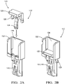
- the CLA system 112 also comprises a third CLA feature 116. Referring now to FIGS. 2A-2B and with continued reference to the previous FIGS., exploded and perspective views of an example configuration of the CLA system 112 according to some implementations of the present disclosure are illustrated.
- the third CLA feature 116 is a clip feature that defines a top/base member 120, a bottom/clip member 124, and opposing outer clip members 128.
- the cover member 108 defines the first CLA feature 132 in addition to a machine-readable indicator 136 defined by the cover member 108 that is also part of the CLA system 112.
- the electrical center 104 e.g., its housing
- these first and second CLA features 132, 140 are engageable notches that slidably engage each other but do not provide locking functionality.
- FIGS. front views of partially engaged and fully engaged configurations of the CLA system 112 including the machine-readable indicator 136 and zoomed-in perspective views and cross-sectional views of the cover 100 and the electrical center 104 according to some implementations of the present disclosure are illustrated.
- the machine-readable indicator 136 is configured to be fully visible and readable by a CLA device (not shown) when the third CLA feature 116 is fully engaged and seated within the first and second CLA features 132, 140.
- a CLA device not shown
- the second CLA feature 140 defined in a housing 144 of the electrical center 104
- a clip member 148 of the second CLA feature 140 are illustrated in greater detail.
- the machine-readable indicator is a two-dimensional data matrix or barcode, such as a quick response (QR) code or the like. It will be appreciated that other suitable machine-readable indicators could be utilized, provided that they are only partially visible when the third CLA feature 116 is only partially engaged, as shown in FIG. 3A .
- the CLA device is not explicitly shown, it will be appreciated that one skilled in the art recognizes that the CLA device could be any handheld or robotically-controlled scanning or reading device for machine-readable indicators (a camera, an infrared scanner, etc.). By requiring full engagement and seating of the third CLA feature 116 in order to then read the machine-readable indicator 136, full engagement of the cover 100 to the electrical center 104 can be assured.
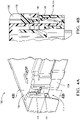
- FIGS. 5A-5C cross-sectional views of the first, second, and third CLA features 132, 140, and 116 at various stages of engagement according to some implementations of the present disclosure are illustrated in greater detail.
- the third CLA feature 116 is partially engaged up to a point where the bottom/clip member 124 contacts a surface 152 of the cover member 108. Beyond this point, the third CLA feature 116 is engaged with the first CLA feature 132 but still removable from the cover member 108 (i.e., the second CLA feature 132).
- FIG. 5A the third CLA feature 116 is partially engaged up to a point where the bottom/clip member 124 contacts a surface 152 of the cover member 108. Beyond this point, the third CLA feature 116 is engaged with the first CLA feature 132 but still removable from the cover member 108 (i.e., the second CLA feature 132).
- FIG. 5A the third CLA feature 116 is partially engaged up to a point where the bottom/clip member 124 contacts a surface 152 of the
- the third CLA feature 116 is partially engaged such that the bottom/clip member 124 of the third CLA feature 116 engages with the clip member 148 of the second CLA feature 140. This represents engagement of the third CLA feature 116 with both the first and second CLA features 132, 140, but not full engagement.
- the third CLA feature 116 is fully engaged and seated with the clip member 148 of the second CLA feature 140 (the electrical center 104) being engaged with the surface 152 of the second CLA feature 132 (the cover member 108).
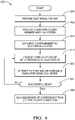
- FIG. 6 a flow diagram of an example method 200 of assembling a portion of an electrical system of a vehicle and, more particularly, covering an electrical center of the vehicle, according to some implementations of the present disclosure, is illustrated. While the components of FIGS. 1-5C are generally referenced, it will be appreciated that the method 200 could be applicable to the assembly of any suitable electrical centers/systems.
- the electrical center 104 is provided.
- the cover 100 comprising the cover member 108 and the CLA system 112 is provided.
- the cover member 108 is connected to or engaged with the electrical center 104.
- the third CLA feature 116 is engaged with the first and second CLA features 132, 140.
- an attempt is made by the CLA device to read the machine-readable indicator 136. This could also be described as a scanning operation or read attempt.
- a determination is made (e.g., by the CLA device or a robotic installer) whether the machine-readable indicator 136 was successfully read. For example, when the third CLA feature 116 is only partially engaged and not fully seated, the machine-readable indicator 136 is not fully visible and therefore not machine-readable.
- assurance of the cover-electrical center locked connection is made at 228 and the method 200 ends or returns to 204 for another cycle. Otherwise, the method 200 returns to 216 where engagement of the third CLA feature 116 continues and another attempt is made to assure the cover-electrical center locked connection.
- Example embodiments are provided so that this disclosure will be thorough, and will fully convey the scope to those who are skilled in the art. Numerous specific details are set forth such as examples of specific components, devices, and methods, to provide a thorough understanding of embodiments of the present disclosure. It will be apparent to those skilled in the art that specific details need not be employed, that example embodiments may be embodied in many different forms and that neither should be construed to limit the scope of the disclosure. In some example embodiments, well-known procedures, well-known device structures, and well-known technologies are not described in detail.
- first, second, third, etc. may be used herein to describe various elements, components, regions, layers and/or sections, these elements, components, regions, layers and/or sections should not be limited by these terms. These terms may be only used to distinguish one element, component, region, layer or section from another region, layer or section. Terms such as “first,” “second,” and other numerical terms when used herein do not imply a sequence or order unless clearly indicated by the context. Thus, a first element, component, region, layer or section discussed below could be termed a second element, component, region, layer or section without departing from the teachings of the example embodiments.
- module may refer to, be part of, or include: an Application Specific Integrated Circuit (ASIC); an electronic circuit; a combinational logic circuit; a field programmable gate array (FPGA); a processor or a distributed network of processors (shared, dedicated, or grouped) and storage in networked clusters or datacenters that executes code or a process; other suitable components that provide the described functionality; or a combination of some or all of the above, such as in a system-on-chip.
- the term module may also include memory (shared, dedicated, or grouped) that stores code executed by the one or more processors.
- code may include software, firmware, byte-code and/or microcode, and may refer to programs, routines, functions, classes, and/or objects.
- shared means that some or all code from multiple modules may be executed using a single (shared) processor. In addition, some or all code from multiple modules may be stored by a single (shared) memory.
- group means that some or all code from a single module may be executed using a group of processors. In addition, some or all code from a single module may be stored using a group of memories.
- the techniques described herein may be implemented by one or more computer programs executed by one or more processors.
- the computer programs include processor-executable instructions that are stored on a non-transitory tangible computer readable medium.
- the computer programs may also include stored data.
- Non-limiting examples of the non-transitory tangible computer readable medium are nonvolatile memory, magnetic storage, and optical storage.
- the present disclosure also relates to an apparatus for performing the operations herein.
- This apparatus may be specially constructed for the required purposes, or it may comprise a general-purpose computer selectively activated or reconfigured by a computer program stored on a computer readable medium that can be accessed by the computer.
- a computer program may be stored in a tangible computer readable storage medium, such as, but is not limited to, any type of disk including floppy disks, optical disks, CD-ROMs, magnetic-optical disks, read-only memories (ROMs), random access memories (RAMs), EPROMs, EEPROMs, magnetic or optical cards, application specific integrated circuits (ASICs), or any type of media suitable for storing electronic instructions, and each coupled to a computer system bus.
- the computers referred to in the specification may include a single processor or may be architectures employing multiple processor designs for increased computing capability.
Landscapes
- Engineering & Computer Science (AREA)
- Microelectronics & Electronic Packaging (AREA)
- Mechanical Engineering (AREA)
- Casings For Electric Apparatus (AREA)
Applications Claiming Priority (1)
| Application Number | Priority Date | Filing Date | Title |
|---|---|---|---|
| US16/952,277 US11558972B2 (en) | 2020-11-19 | 2020-11-19 | Electrical center cover with machine-readable indicator confirmation of lock engagement |
Publications (1)
| Publication Number | Publication Date |
|---|---|
| EP4059778A1 true EP4059778A1 (de) | 2022-09-21 |
Family
ID=78709294
Family Applications (1)
| Application Number | Title | Priority Date | Filing Date |
|---|---|---|---|
| EP21209258.9A Pending EP4059778A1 (de) | 2020-11-19 | 2021-11-19 | Elektrischer mitteldeckel mit maschinenlesbarer anzeigebestätigung für schlosseinrastung |
Country Status (3)
| Country | Link |
|---|---|
| US (1) | US11558972B2 (de) |
| EP (1) | EP4059778A1 (de) |
| CN (1) | CN114521076A (de) |
Families Citing this family (2)
| Publication number | Priority date | Publication date | Assignee | Title |
|---|---|---|---|---|
| CN114093244A (zh) * | 2021-11-18 | 2022-02-25 | 武汉华星光电技术有限公司 | 背光模组及电子装置 |
| US12356564B2 (en) | 2023-08-22 | 2025-07-08 | Ford Global Technologies, Llc | Power distribution assembly |
Citations (3)
| Publication number | Priority date | Publication date | Assignee | Title |
|---|---|---|---|---|
| US9583860B1 (en) * | 2015-11-24 | 2017-02-28 | Te Connectivity Corporation | Electrical connector with recordable position assurance |
| US20170229813A1 (en) * | 2016-02-10 | 2017-08-10 | Yazaki North America, Inc. | Connector position assurance with identification feature |
| US9801296B1 (en) * | 2017-01-16 | 2017-10-24 | Dinkle Enterprise Co., Ltd. | Housing device having pull-type locking and release structure |
Family Cites Families (19)
| Publication number | Priority date | Publication date | Assignee | Title |
|---|---|---|---|---|
| US3027168A (en) | 1957-12-05 | 1962-03-27 | Heinrich J B Herbruggen | Packing ring |
| US6431880B1 (en) | 1998-06-22 | 2002-08-13 | Cooper Technologies | Modular terminal fuse block |
| US7134921B2 (en) | 2004-04-15 | 2006-11-14 | Erico International Corporation | Power distribution block assembly |
| US7375300B2 (en) * | 2005-09-08 | 2008-05-20 | Illinois Tool Works Inc. | Switch assembly |
| US7700875B2 (en) * | 2006-12-22 | 2010-04-20 | Thomas & Betts International, Inc. | Switch box extender grounding strap |
| JP4916955B2 (ja) * | 2007-06-07 | 2012-04-18 | 矢崎総業株式会社 | 電子部品内蔵ユニット |
| US7727022B2 (en) | 2008-02-14 | 2010-06-01 | Delphi Technologies, Inc. | On harness PCB electrical center |
| US7845959B2 (en) | 2009-01-06 | 2010-12-07 | Cooper Technologies Company | Component position assurance element for a power distribution block |
| US20120268864A1 (en) * | 2011-04-21 | 2012-10-25 | Delphi Technologies, Inc. | Apparatus having plurality of openings to access removable electronic devices some of which have electrical connections using no circuit board trace |
| US8721374B2 (en) * | 2011-07-22 | 2014-05-13 | Lear Corporation | Electrical connector |
| US9622355B2 (en) | 2013-07-08 | 2017-04-11 | Delphi Technologies, Inc. | Environmentally sealed electrical housing assembly with integrated connector |
| MX2017005407A (es) * | 2014-10-31 | 2017-10-04 | CommScope Connectivity Belgium BVBA | Cerradura de seguridad de cierre garantizado. |
| KR101609705B1 (ko) * | 2015-12-08 | 2016-04-06 | 영화테크(주) | 정션박스 |
| JP6575930B2 (ja) * | 2016-06-02 | 2019-09-18 | 株式会社オートネットワーク技術研究所 | 基板ユニット |
| AU2016410602B2 (en) * | 2016-06-23 | 2022-07-28 | Landis+Gyr Technology, Inc. | Utility meter enclosure with dual position locks |
| JP2018073791A (ja) * | 2016-11-04 | 2018-05-10 | 住友電装株式会社 | 電気接続箱 |
| US10604924B2 (en) * | 2016-12-13 | 2020-03-31 | Newtonoid Technologies, L.L.C. | Smart urinals and methods of making and using same |
| DE102017204600A1 (de) * | 2017-03-20 | 2018-09-20 | Robert Bosch Gmbh | Verbinder zum Verbinden von zwei Gehäuseteilen und Gehäuse umfassend zwei Gehäuseteile und mindestens einen Verbinder |
| JP7214615B2 (ja) * | 2019-12-05 | 2023-01-30 | 株式会社東芝 | 接続デバイス |
-
2020
- 2020-11-19 US US16/952,277 patent/US11558972B2/en active Active
-
2021
- 2021-11-19 CN CN202111376105.3A patent/CN114521076A/zh active Pending
- 2021-11-19 EP EP21209258.9A patent/EP4059778A1/de active Pending
Patent Citations (3)
| Publication number | Priority date | Publication date | Assignee | Title |
|---|---|---|---|---|
| US9583860B1 (en) * | 2015-11-24 | 2017-02-28 | Te Connectivity Corporation | Electrical connector with recordable position assurance |
| US20170229813A1 (en) * | 2016-02-10 | 2017-08-10 | Yazaki North America, Inc. | Connector position assurance with identification feature |
| US9801296B1 (en) * | 2017-01-16 | 2017-10-24 | Dinkle Enterprise Co., Ltd. | Housing device having pull-type locking and release structure |
Also Published As
| Publication number | Publication date |
|---|---|
| US20220159858A1 (en) | 2022-05-19 |
| CN114521076A (zh) | 2022-05-20 |
| US11558972B2 (en) | 2023-01-17 |
Similar Documents
| Publication | Publication Date | Title |
|---|---|---|
| EP4059778A1 (de) | Elektrischer mitteldeckel mit maschinenlesbarer anzeigebestätigung für schlosseinrastung | |
| CN108491301B (zh) | 电子装置、基于redis的异常预警方法及存储介质 | |
| US20080181407A1 (en) | Method for protecting a control device against manipulation | |
| WO2006028657A1 (en) | Volatile storage based power loss recovery mechanism | |
| EP0897144A2 (de) | Verfahren und Vorrichtung zum Zugriffsschutz in einer integrierten Schaltung | |
| CN113641873B (zh) | 数据处理方法、装置、电子设备及可读存储介质 | |
| CN111241604A (zh) | 与用于存储器安全的存储器停用有关的设备和方法 | |
| EP1532528A2 (de) | Verfahren zur sicherung der ausführung eines programms gegen angriffen | |
| EP2996034A1 (de) | Ausführungsflussschutz in Mikrocontrollern | |
| US8582765B2 (en) | Masking of data in a calculation | |
| CN110751116B (zh) | 一种目标识别的方法及装置 | |
| CN109388976B (zh) | 用于屏蔽rsa运算的系统和方法 | |
| US20080263533A1 (en) | Implementation of patches by a processing unit | |
| CN112633281A (zh) | 一种基于Hash算法车辆身份认证方法及系统 | |
| CN111027046A (zh) | 一种usb网络设备的访问控制方法和装置 | |
| JP2010134644A (ja) | Icカードおよびパッチ実行方法 | |
| US20140009260A1 (en) | System and Method for Querying Vehicle Status at a Checkpoint using Identity Information | |
| CN106445807B (zh) | 用于智能终端的应用安装包检测方法及装置 | |
| CN116070293A (zh) | 一种通过芯片加密进行固件保护的处理方法和装置 | |
| JP2018116355A (ja) | 車載機器 | |
| CN100487650C (zh) | 具有可插拔式基本输出入系统之计算机装置 | |
| US20050055571A1 (en) | Unauthorized access embedded software protection system | |
| CN116679324B (zh) | 双星故障识别的方法、装置、电子设备及存储介质 | |
| CN114996710B (zh) | 分支记录实现方法及系统 | |
| Rice et al. | Dependable coding of fiducial tags |
Legal Events
| Date | Code | Title | Description |
|---|---|---|---|
| PUAI | Public reference made under article 153(3) epc to a published international application that has entered the european phase |
Free format text: ORIGINAL CODE: 0009012 |
|
| STAA | Information on the status of an ep patent application or granted ep patent |
Free format text: STATUS: THE APPLICATION HAS BEEN PUBLISHED |
|
| AK | Designated contracting states |
Kind code of ref document: A1 Designated state(s): AL AT BE BG CH CY CZ DE DK EE ES FI FR GB GR HR HU IE IS IT LI LT LU LV MC MK MT NL NO PL PT RO RS SE SI SK SM TR |
|
| STAA | Information on the status of an ep patent application or granted ep patent |
Free format text: STATUS: REQUEST FOR EXAMINATION WAS MADE |
|
| RAP3 | Party data changed (applicant data changed or rights of an application transferred) |
Owner name: APTIV TECHNOLOGIES LIMITED |
|
| 17P | Request for examination filed |
Effective date: 20230321 |
|
| RBV | Designated contracting states (corrected) |
Designated state(s): AL AT BE BG CH CY CZ DE DK EE ES FI FR GB GR HR HU IE IS IT LI LT LU LV MC MK MT NL NO PL PT RO RS SE SI SK SM TR |
|
| RAP1 | Party data changed (applicant data changed or rights of an application transferred) |
Owner name: APTIV TECHNOLOGIES AG |
|
| STAA | Information on the status of an ep patent application or granted ep patent |
Free format text: STATUS: EXAMINATION IS IN PROGRESS |
|
| RAP3 | Party data changed (applicant data changed or rights of an application transferred) |
Owner name: APTIV TECHNOLOGIES AG |
|
| 17Q | First examination report despatched |
Effective date: 20240916 |