EP4059774A1 - Valve, valve arrangement and seat comfort system - Google Patents
Valve, valve arrangement and seat comfort system Download PDFInfo
- Publication number
- EP4059774A1 EP4059774A1 EP22161711.1A EP22161711A EP4059774A1 EP 4059774 A1 EP4059774 A1 EP 4059774A1 EP 22161711 A EP22161711 A EP 22161711A EP 4059774 A1 EP4059774 A1 EP 4059774A1
- Authority
- EP
- European Patent Office
- Prior art keywords
- valve
- measuring
- measuring device
- wire
- air mass
- Prior art date
- Legal status (The legal status is an assumption and is not a legal conclusion. Google has not performed a legal analysis and makes no representation as to the accuracy of the status listed.)
- Pending
Links
- 238000010438 heat treatment Methods 0.000 claims description 11
- 238000012545 processing Methods 0.000 claims description 3
- 238000011156 evaluation Methods 0.000 description 15
- 238000005259 measurement Methods 0.000 description 15
- 230000001276 controlling effect Effects 0.000 description 12
- 239000012530 fluid Substances 0.000 description 11
- 238000000034 method Methods 0.000 description 9
- 230000008859 change Effects 0.000 description 8
- 230000004913 activation Effects 0.000 description 7
- 230000006870 function Effects 0.000 description 6
- 229910001285 shape-memory alloy Inorganic materials 0.000 description 4
- 238000001514 detection method Methods 0.000 description 3
- 238000012544 monitoring process Methods 0.000 description 3
- 238000007789 sealing Methods 0.000 description 3
- 230000008901 benefit Effects 0.000 description 2
- 238000004891 communication Methods 0.000 description 2
- 230000000052 comparative effect Effects 0.000 description 2
- 238000011161 development Methods 0.000 description 2
- 239000000463 material Substances 0.000 description 2
- BASFCYQUMIYNBI-UHFFFAOYSA-N platinum Chemical compound [Pt] BASFCYQUMIYNBI-UHFFFAOYSA-N 0.000 description 2
- 208000007623 Lordosis Diseases 0.000 description 1
- 238000005299 abrasion Methods 0.000 description 1
- 229910045601 alloy Inorganic materials 0.000 description 1
- 239000000956 alloy Substances 0.000 description 1
- 238000009529 body temperature measurement Methods 0.000 description 1
- 238000012937 correction Methods 0.000 description 1
- 125000004122 cyclic group Chemical group 0.000 description 1
- 230000001419 dependent effect Effects 0.000 description 1
- 238000013461 design Methods 0.000 description 1
- 238000005485 electric heating Methods 0.000 description 1
- 238000002474 experimental method Methods 0.000 description 1
- 230000001771 impaired effect Effects 0.000 description 1
- 238000009434 installation Methods 0.000 description 1
- 230000010354 integration Effects 0.000 description 1
- 239000007788 liquid Substances 0.000 description 1
- 239000002184 metal Substances 0.000 description 1
- 229910052751 metal Inorganic materials 0.000 description 1
- 239000007769 metal material Substances 0.000 description 1
- 239000002245 particle Substances 0.000 description 1
- 229910052697 platinum Inorganic materials 0.000 description 1
- 230000008569 process Effects 0.000 description 1
- 230000001105 regulatory effect Effects 0.000 description 1
- 238000004904 shortening Methods 0.000 description 1
- 239000002520 smart material Substances 0.000 description 1
- 239000013589 supplement Substances 0.000 description 1
- WFKWXMTUELFFGS-UHFFFAOYSA-N tungsten Chemical compound [W] WFKWXMTUELFFGS-UHFFFAOYSA-N 0.000 description 1
- 229910052721 tungsten Inorganic materials 0.000 description 1
- 239000010937 tungsten Substances 0.000 description 1
Images


Classifications
-
- F—MECHANICAL ENGINEERING; LIGHTING; HEATING; WEAPONS; BLASTING
- F16—ENGINEERING ELEMENTS AND UNITS; GENERAL MEASURES FOR PRODUCING AND MAINTAINING EFFECTIVE FUNCTIONING OF MACHINES OR INSTALLATIONS; THERMAL INSULATION IN GENERAL
- F16K—VALVES; TAPS; COCKS; ACTUATING-FLOATS; DEVICES FOR VENTING OR AERATING
- F16K31/00—Actuating devices; Operating means; Releasing devices
- F16K31/02—Actuating devices; Operating means; Releasing devices electric; magnetic
- F16K31/025—Actuating devices; Operating means; Releasing devices electric; magnetic actuated by thermo-electric means
-
- F—MECHANICAL ENGINEERING; LIGHTING; HEATING; WEAPONS; BLASTING
- F16—ENGINEERING ELEMENTS AND UNITS; GENERAL MEASURES FOR PRODUCING AND MAINTAINING EFFECTIVE FUNCTIONING OF MACHINES OR INSTALLATIONS; THERMAL INSULATION IN GENERAL
- F16K—VALVES; TAPS; COCKS; ACTUATING-FLOATS; DEVICES FOR VENTING OR AERATING
- F16K31/00—Actuating devices; Operating means; Releasing devices
- F16K31/004—Actuating devices; Operating means; Releasing devices actuated by piezoelectric means
- F16K31/005—Piezo-electric benders
-
- B—PERFORMING OPERATIONS; TRANSPORTING
- B60—VEHICLES IN GENERAL
- B60N—SEATS SPECIALLY ADAPTED FOR VEHICLES; VEHICLE PASSENGER ACCOMMODATION NOT OTHERWISE PROVIDED FOR
- B60N2/00—Seats specially adapted for vehicles; Arrangement or mounting of seats in vehicles
- B60N2/02—Seats specially adapted for vehicles; Arrangement or mounting of seats in vehicles the seat or part thereof being movable, e.g. adjustable
- B60N2/0224—Non-manual adjustments, e.g. with electrical operation
-
- B—PERFORMING OPERATIONS; TRANSPORTING
- B60—VEHICLES IN GENERAL
- B60N—SEATS SPECIALLY ADAPTED FOR VEHICLES; VEHICLE PASSENGER ACCOMMODATION NOT OTHERWISE PROVIDED FOR
- B60N2/00—Seats specially adapted for vehicles; Arrangement or mounting of seats in vehicles
- B60N2/64—Back-rests or cushions
- B60N2/66—Lumbar supports
- B60N2/665—Lumbar supports using inflatable bladders
-
- B—PERFORMING OPERATIONS; TRANSPORTING
- B60—VEHICLES IN GENERAL
- B60N—SEATS SPECIALLY ADAPTED FOR VEHICLES; VEHICLE PASSENGER ACCOMMODATION NOT OTHERWISE PROVIDED FOR
- B60N2/00—Seats specially adapted for vehicles; Arrangement or mounting of seats in vehicles
- B60N2/90—Details or parts not otherwise provided for
- B60N2/914—Hydro-pneumatic adjustments of the shape
-
- F—MECHANICAL ENGINEERING; LIGHTING; HEATING; WEAPONS; BLASTING
- F16—ENGINEERING ELEMENTS AND UNITS; GENERAL MEASURES FOR PRODUCING AND MAINTAINING EFFECTIVE FUNCTIONING OF MACHINES OR INSTALLATIONS; THERMAL INSULATION IN GENERAL
- F16K—VALVES; TAPS; COCKS; ACTUATING-FLOATS; DEVICES FOR VENTING OR AERATING
- F16K31/00—Actuating devices; Operating means; Releasing devices
- F16K31/02—Actuating devices; Operating means; Releasing devices electric; magnetic
- F16K31/06—Actuating devices; Operating means; Releasing devices electric; magnetic using a magnet, e.g. diaphragm valves, cutting off by means of a liquid
-
- F—MECHANICAL ENGINEERING; LIGHTING; HEATING; WEAPONS; BLASTING
- F16—ENGINEERING ELEMENTS AND UNITS; GENERAL MEASURES FOR PRODUCING AND MAINTAINING EFFECTIVE FUNCTIONING OF MACHINES OR INSTALLATIONS; THERMAL INSULATION IN GENERAL
- F16K—VALVES; TAPS; COCKS; ACTUATING-FLOATS; DEVICES FOR VENTING OR AERATING
- F16K37/00—Special means in or on valves or other cut-off apparatus for indicating or recording operation thereof, or for enabling an alarm to be given
- F16K37/0025—Electrical or magnetic means
- F16K37/0041—Electrical or magnetic means for measuring valve parameters
-
- F—MECHANICAL ENGINEERING; LIGHTING; HEATING; WEAPONS; BLASTING
- F16—ENGINEERING ELEMENTS AND UNITS; GENERAL MEASURES FOR PRODUCING AND MAINTAINING EFFECTIVE FUNCTIONING OF MACHINES OR INSTALLATIONS; THERMAL INSULATION IN GENERAL
- F16K—VALVES; TAPS; COCKS; ACTUATING-FLOATS; DEVICES FOR VENTING OR AERATING
- F16K37/00—Special means in or on valves or other cut-off apparatus for indicating or recording operation thereof, or for enabling an alarm to be given
- F16K37/0025—Electrical or magnetic means
- F16K37/005—Electrical or magnetic means for measuring fluid parameters
-
- G—PHYSICS
- G05—CONTROLLING; REGULATING
- G05D—SYSTEMS FOR CONTROLLING OR REGULATING NON-ELECTRIC VARIABLES
- G05D7/00—Control of flow
- G05D7/06—Control of flow characterised by the use of electric means
- G05D7/0617—Control of flow characterised by the use of electric means specially adapted for fluid materials
- G05D7/0629—Control of flow characterised by the use of electric means specially adapted for fluid materials characterised by the type of regulator means
- G05D7/0635—Control of flow characterised by the use of electric means specially adapted for fluid materials characterised by the type of regulator means by action on throttling means
-
- G—PHYSICS
- G01—MEASURING; TESTING
- G01F—MEASURING VOLUME, VOLUME FLOW, MASS FLOW OR LIQUID LEVEL; METERING BY VOLUME
- G01F1/00—Measuring the volume flow or mass flow of fluid or fluent solid material wherein the fluid passes through a meter in a continuous flow
- G01F1/56—Measuring the volume flow or mass flow of fluid or fluent solid material wherein the fluid passes through a meter in a continuous flow by using electric or magnetic effects
-
- G—PHYSICS
- G01—MEASURING; TESTING
- G01F—MEASURING VOLUME, VOLUME FLOW, MASS FLOW OR LIQUID LEVEL; METERING BY VOLUME
- G01F1/00—Measuring the volume flow or mass flow of fluid or fluent solid material wherein the fluid passes through a meter in a continuous flow
- G01F1/68—Measuring the volume flow or mass flow of fluid or fluent solid material wherein the fluid passes through a meter in a continuous flow by using thermal effects
-
- G—PHYSICS
- G01—MEASURING; TESTING
- G01F—MEASURING VOLUME, VOLUME FLOW, MASS FLOW OR LIQUID LEVEL; METERING BY VOLUME
- G01F1/00—Measuring the volume flow or mass flow of fluid or fluent solid material wherein the fluid passes through a meter in a continuous flow
- G01F1/76—Devices for measuring mass flow of a fluid or a fluent solid material
Definitions
- the invention relates to a valve, in particular a valve of a seat comfort system.
- the invention also relates to a valve arrangement and a seat comfort system.
- a circuit arrangement for controlling a system in particular a lumbar support with at least two air cushions.
- the known circuit is therefore suitable for a seat comfort system.
- a seat comfort system is a system for a seat comfort function of a seat, for example a vehicle seat.
- a seat comfort system can include a pneumatic lumbar support device and/or a massage device for a seat.
- a seat comfort system typically includes a plurality of air cushions, which can be filled and subjected to a desired pressure, which may vary over time.
- the seat comfort system comprises a control unit, a pump for applying compressed air to the air cushions and a plurality of valves, with at least one valve being expediently assigned to each air cushion.
- Each of these valves can include an actuator with an SMA element (SMA: shape memory alloy), ie an element made of a shape memory alloy, which, depending on the current supply, puts the valve in an open, partially open or closed functional state.
- SMA element is an SMA wire.
- the power supplied must usually be in must be kept in a very narrowly defined range in order to ensure reliable activation of the actuator while still avoiding thermal overload and thus permanent damage to the SMA element. Sensors for current, voltage and/or temperature monitoring are therefore expediently assigned to the control unit.
- FIG. 1A, Figure 1B and Figure 1C show a circuit arrangement of several valves 120 of a seat comfort system 2 according to the prior art.
- the circuit arrangement 1 is suitable, for example, for controlling the valves of a seat comfort system 2 comprising a lumbar support device with at least two air cushions (not shown).
- a seat comfort system 2 thus comprises at least two air cushions, which have at least one valve 120 (see Figure 1B , Figure 1C ), in particular at least one valve 120 each.
- a valve 120 comprises, as exemplified in Figure 1B shown, a valve housing 102 and an actuator 103.
- the valve housing 102 includes a first opening 105 and a second opening 106.
- the housing encloses a valve chamber 109.
- the actuator 103 includes an SMA element 100, which as a V-shaped arranged SMA wire is executed, and a movable with the SMA element 100 actuating element 104, which is provided with a sealing element 108 in order to selectively open or close the first opening 105.
- the first opening 105 is open when the actuating element 104 is in a first position and is closed when the actuating element 104 is in a second position.
- a valve can have a limit switch 107 which is closed when the second position is reached.
- a heating power supplied to the SMA element 100 can be partially or completely reduced by means of this limit switch.
- a circuit with a temperature sensor that adjusts the heating output to the ambient temperature.
- an actuator 103 with a linear or U-shaped SMA element 100 is known, in which the actuating element 104 can be formed, for example, from a leaf spring, at the first end of which the SMA element 100 acts.
- a through hole 104a of the actuating element 104 at the first end of the actuating element 104 .
- the actuating element 104 is arranged with its other end between a base plate 111 and a printed circuit board or printed circuit board 110 , with the SMA element 100 being able to be held and contacted by means of a crimp 101 .
- the circuit arrangement shown is suitable for energizing and switching a plurality of SMA elements 100-1 to 100-N.
- the SMA elements 100-1 to 100-N are connected to a voltage source U represented by the arrow.
- the circuit arrangement 1 includes a control unit 30.
- a temperature sensor 70 for measuring the ambient temperature of the SMA elements 100 and/or a voltage sensor 71 can be present.
- the control unit 30 is connected to a pulse width modulation device 60 .
- the pulse width modulation device 60 can be used to control the SMA elements 100-1 to 100-N by means of pulse width modulation, with the duty cycle of the pulse width modulation, i.e. the ratio of pulse width to period, being set depending on the measured supply voltage and temperature.
- a circuit for a pulse width modulation is, for example, from DE 10 2017 112 803 A1 known.
- the associated SMA element 100-1 to 100-N can be supplied with current in succession by means of the respective driver 20-1 to 20-N.
- series resistors 21-1 to 21-N can be present.
- the circuit arrangement can also include a limit switch or a feedback device 38 .
- the feedback device 38 is connected either to the pulse width modulation device 60 as shown or alternatively to the control unit 30 and is suitable for reporting to the pulse width modulation device 60 or the control unit 30 when the actuator has reached an end position, which is mechanically detected.
- a pneumatic valve with an actuator and movable shut-off elements is known, the actuator being controlled by a means electric heating power deformable SMA element is actuated.
- the SMA element is supplied with electrical heating power, whereupon the SMA element deforms in a manner known per se and this causes a predetermined movement of the shut-off element to open or close an air connection.
- the deformation of the SMA element is reversed upon termination of the application of the electrical heating power, thereby causing the predetermined movement of the SMA element to be reversed.
- the known actuator also includes a detection unit in order to detect when an end position is reached and left. The final position is achieved in the embodiment shown by bridging a portion of the SMA element and measuring a resistance reduced by the bridging.
- a control device for the adjustment of air cushions is known.
- the running time of a pump is recorded and, taking into account the flow rate of the pump, an amount of air supplied to the at least one air cushion or an air volume supplied is determined.
- a method for monitoring the pressure in a pneumatic seat adjustment device is known. To do this, the pressure in each air chamber or a supply channel is measured with a pressure sensor.
- the known methods are based on the fact that a type of switch, which is realized by a toggle switch or a bypass, is actuated in each case at a specific position of the actuating element.
- Such mechanical switches can be impaired in their function by dirt particles, abrasion, liquids, but also a high switching frequency.
- the object of the invention is to specify a new valve, in particular a valve which is improved over the prior art.
- a further object is to specify a valve arrangement and a seat comfort system with such valves.
- the valve according to the invention is, for example, a valve of a seat comfort system.
- the seat comfort system can include one or more valves.
- the seat comfort system can be used or used in a vehicle seat, for example.
- the seat comfort system can be, for example, a lumbar support device and/or massage device.
- the seat comfort system typically includes one or more air cushions, which are usually arranged in a seat, in particular a vehicle seat.
- the valve according to the invention comprises a valve housing, wherein the valve housing can have, for example, a housing cover, a housing base and an intermediate housing arranged between the housing cover and the housing base.
- the valve housing has at least one first opening and at least one second opening, and the valve housing encloses a valve chamber. This may include a flow chamber and an actuation chamber.
- the valve comprises an actuator with an actuating element for opening or closing the valve, for example the first and/or second opening or an opening within the valve, for example an opening between the flow and the actuation chamber, and expediently a restoring element.
- the actuating element can be adjusted at least between a first position and a second position.
- the first position and second position are two positions that are different from one another and can be selected as the open and closed position of the valve or as intermediate positions.
- the actuator can, for example, comprise a piezoelectric element or a magnetic element, in particular an electromagnetic element, or an SMA element (shape memory alloy element).
- the valve according to the invention comprises at least one air mass measuring device for measuring an air mass flowing through the valve or at least one measuring wire of an air mass measuring device for measuring an air mass flowing through the valve.
- the air mass flowing through the valve can be determined, for example, as explained in more detail below, by means of a measuring wire, past which the air mass to be measured flows, causing a temperature change on or in the vicinity of the measuring wire.
- the air mass flowing through the valve can thus be used to determine or at least estimate how much air or what quantity of air is in an associated air cushion, for example of the seat comfort system.
- the measured values of the air mass measuring device can be compared with stored comparison values and/or parallel reference measurements can be made in areas where there is no air flow, for example on additional reference measuring wires.
- One advantage of the invention is that the air mass and thus the amount of air flowing through the valve can be determined by means of the valve. Based on the air mass flowing through the valve, it can therefore be determined or at least estimated how much air is, for example, in an assigned air cushion, for example a seat comfort system.
- the air mass measuring device can include at least one measuring wire, the measuring wire being arranged within the valve housing and/or in the valve chamber and/or in the first opening and/or in the second opening.
- the measuring wire can be arranged in the flow chamber of the valve.
- the change in the measured values which is determined by means of the measuring device, depends on the amount of heat withdrawn from the measuring wire by the air passing by and is therefore an indicator for the air mass to be determined.
- resistance should be understood to mean electrical resistance.
- the measuring device is part of a circuit arrangement for controlling the valve, the circuit arrangement having at least one driver unit for actuating the actuator and a control unit for controlling the driver unit, and the control unit being suitable for processing an output signal of the measuring device of the air mass measuring device.
- the control unit is thus set up in such a way that it processes an output signal and thus a measurement result of the air mass measuring device and thus uses this measurement result, for example, to control the driver unit to actuate the actuator, i.e. for example to close the valve when a predetermined threshold value of the air mass or air quantity flowing through is reached.
- the valve according to the invention thus enables, for example, when filling or emptying air cushions, in particular contactless, detection of one or more predetermined filling states of the air cushion and can control or regulate the valve accordingly, for example closing or opening the valve.
- the air mass measuring device therefore generates, for example based on the measurement of temperature and/or heating current and/or electrical power consumption and/or resistance of at least one measuring wire of the air mass measuring device and/or the change in these measured variables over time, an output signal that the flowed through the valve Air mass and thus also the air volume characterizes.
- This output signal is forwarded to the control unit, so that the control unit can, for example, control or regulate the driver unit based on the measured air mass or air quantity.
- the output signal of the respective measuring device explained above is forwarded to the control unit, so that the control unit can control or regulate the driver unit based on the measured value of the measuring device.
- the circuit arrangement can be designed so that either the resistance, the current and/or the power of the measuring wire is measured or current is applied, i.e. the measuring device and driver unit are alternately actively connected to the measuring wire, which is particularly useful when the measuring wire is SMA element, i.e. an SMA wire, which is also an element of the valve actuator. This is explained in more detail below.
- the driver unit can also be measured and controlled simultaneously or alternately. It can be provided that the control unit also controls the resistance measuring device and/or the temperature sensor and/or the temperature measuring device and/or the current measuring device and/or the power measuring device.
- the actuator of the valve has an SMA element.
- this can be an SMA wire, which is understood to mean a wire-shaped but also a strip-shaped SMA element.
- the SMA wire can then be the measuring wire or one of the measuring wires of the air mass measuring device. If necessary, one or more additional measuring wires of the air mass measuring device can be provided.
- the air mass measuring device comprises a measuring device, in particular a resistance measuring device, and that the circuit arrangement is designed such that the measuring device and the driver unit are operatively connected alternately to the SMA element, specifically the SMA wire. This alternating control can be implemented by the appropriately set up control unit.
- the control unit can also control the air mass measuring device in addition to the driver unit.
- At least one separate wire that is to say a wire provided in addition to the SMA element, can also be provided, with the separate wire being the measuring wire or one of the measuring wires of the air mass measuring device. If necessary, one or more additional measuring wires of the air mass measuring device can be provided, in which case the SMA element can also be an SMA wire, which is provided as an additional measuring wire.
- the separate wire is thus arranged separately from the SMA element of the actuator.
- This separate wire can be a wire made from an SMA material or from another metallic material, such as tungsten or platinum, or from an alloy.
- the separate wire can, for example, be connected in parallel to the SMA element or elements, but can be controlled differently, that is to say separately from these SMA elements.
- the valve can have additional sensors for current, voltage and/or temperature monitoring.
- the valve, in particular the control unit can have communication interfaces in order to be controlled by switches and/or an on-board computer that are present in a vehicle.
- the valve, in particular the control unit have a LIN (Local Interconnect Network) communication interface, which in particular has a transceiver and/or a switch input interface.
- the switch input interface is particularly suitable for processing resistance-based switch signals, it being possible for the switch input interface to be designed for a plurality of switch inputs, eg for seat adjustment, in particular the seat position, and for lordosis and/or massage functions.
- the control unit may include memory for storing data.
- the valve housing can have at least one valve opening, for example opening from the flow chamber into the actuating chamber, wherein the actuating element, which can be moved axially between a closed position for closing the valve opening and an open position for releasing the valve opening, has a wire inside the actuating chamber for actuating the actuating element in the opening direction.
- the actuating element which can be moved axially between a closed position for closing the valve opening and an open position for releasing the valve opening, has a wire inside the actuating chamber for actuating the actuating element in the opening direction.
- strip-shaped SMA element made of a shape memory alloy, a restoring element serving to move the actuating element in the closing direction, and a printed circuit board are arranged, with one section of the SMA element being fixed to the actuating element and electrically connected at least one end to the printed circuit board for the application of current is.
- the SMA element is fixed to the actuating element with a middle section and is connected to the printed circuit board with both ends.
- the above-mentioned circuit arrangement for controlling the valve, in particular the measuring device can include an evaluation unit or be connected to an evaluation unit.
- the evaluation unit can, for example, record and evaluate specific measured values of the air mass measuring device, for example measured resistance values, temperature values, current strengths and/or power values, and generate an output signal therefrom that is forwarded to the control unit.
- This output signal can in particular include a signal for communicating that an end condition has been reached.
- the circuit arrangement comprises an ASIC (ASIC: application-specific integrated circuit) which has one or more of the following components: the driver unit, in particular with one or more SMA drivers, one or the aforementioned measuring device the air mass measuring device, in particular with an evaluation unit and/or a memory, and the control unit.
- ASIC application-specific integrated circuit
- the measuring device can be a temperature measuring device, resistance measuring device, current measuring device and/or power measuring device.
- valve and/or the circuit arrangement includes additional sensors, in particular an end position switch.
- an end position switch can serve both as a safety measure and as a calibration aid.
- the circuit arrangement is assigned to a large number of valves and thus includes a large number of actuators, with each actuator being assigned a driver unit, in particular a driver unit with an SMA driver, for actuating the respective actuator or an SMA driver in a driver unit for each actuator is.
- the circuit arrangement expediently comprises a multiplexer which is connected to each of the SMA elements of the actuator in such a way that the resistance of each SMA element can be measured individually. Consequently By means of the multiplexer, each SMA element is sequentially connected to the resistance measuring device for measuring the resistance.
- the circuit arrangement for example the evaluation unit and/or the control unit, includes a memory for storing data.
- the memory can also be a shared memory of the evaluation unit and the control unit.
- the control unit is designed, for example, for control using pulse width modulation.
- the control unit includes a pulse width modulation unit, for example.
- the SMA elements are energized one after the other within a duty cycle for a predetermined pulse width and pulse height via the associated SMA driver of the driver unit and are thus heated.
- the pulse width modulation unit can output a time signal to the measuring device, for example a resistance measuring device, and/or the air mass measuring device.
- the measuring device in particular the resistance measuring device, comprises two or more multiplexers, which are each connected to a part of the SMA elements.
- This configuration is possible for large systems with a large number of SMA elements. For example, 20 SMA elements can be provided per multiplexer.
- a series resistor is expediently connected in series between the measuring device, in particular the resistance measuring device, and the SMA element. This series resistor essentially serves to reduce current peaks and thus reduces the risk of overloading the SMA elements.
- valve and/or the circuit arrangement can also be made for the valve and/or the circuit arrangement to include other sensors than those already described above, for example an end position switch.
- the end condition can be or include, for example, reaching a specified air mass value and/or a specified change and/or a filling level, for example of an air cushion.
- the reversal point can be determined by comparing it with the previously measured resistance value or values. A combination of detection of the reversal point and comparison with a specified absolute value increases the accuracy of the method. If a wire made of a different material, eg a metal, is used to determine the air mass, the relationship between resistance and temperature is different.
- a wire made of a different material eg a metal
- the end condition can be selected such that the actuating element is brought into an intermediate position close to the open or closed position, so that an end point of the actuator is not reached with the method according to the invention. This reduces the mechanical stress on the valves.
- the method expediently includes activation by means of pulse width modulation.
- the method can also include measuring the resistance of all SMA elements, with the resistance of all SMA elements being measured in a common activation dead time, or with the measurement of an SMA element taking place between the activation of one SMA element and the activation of another, in particular of the following SMA element.
- the resistance of all SMA elements being measured in a common activation dead time, or with the measurement of an SMA element taking place between the activation of one SMA element and the activation of another, in particular of the following SMA element.
- two or more valves and correspondingly provided two or more actuators each comprising an SMA element.
- the power required to actuate the actuator is calculated by means of the driver unit or read from a table.
- the measured values of the air mass measuring device and/or the measuring device are used and the air mass and/or the air quantity and/or a control signal for the driver unit are determined and/or output from these measured values using stored comparative values and/or a stored table of values becomes. This can take place, for example, in the evaluation unit and/or in the control unit. Alternatively or additionally, the measured values can also be compared, for example, with comparative values of a reference measurement carried out in parallel, for example using a reference measuring wire, and from this the air mass and/or the air quantity and/or control signals for the driver unit can be determined and/or output.
- the valve arrangement according to the invention has several valves according to the invention.
- the circuit arrangement mentioned above for controlling each valve can be integrated into a common circuit arrangement. It can be provided that all the valve housings of the valves are formed together in one piece.
- the valve housings that respectively enclose the valve chamber of a valve in particular comprising intermediate housings and/or housing covers and/or housing bases, can be formed in one piece.
- At least a first part of the plurality of valves has a common pressure connection, which in each case opens into the valve space, in particular into the flow chamber, particularly preferably into a first area of the flow chambers or an area comprising the first areas of the flow chambers, or in each case with the valve space, in particular the flow chamber, particularly preferably the first area of the flow chamber or the area is connected via at least one air duct.
- At least a second part of the Several valves can have a common opening for connection to the atmosphere, which opens in particular into the first area of the flow chamber or an area comprising the first areas of the flow chambers or is connected to the first areas of the flow chambers.
- the measuring wire can be accommodated in each valve, in particular as an SMA wire.
- the measuring wire can also not be accommodated in every valve of the valve arrangement, but instead the wire of the air mass measuring device can be arranged in the air duct to the pressure connection and/or to the common opening for connection to the atmosphere.
- the air mass measuring device can thus in each case comprise a measuring wire for each valve or a measuring wire together for a first part of the plurality of valves and/or a measuring wire together for a second part of the plurality of valves.
- the air mass measuring device can be controlled in such a way that the air mass measurement is only carried out when exactly one valve is open.
- the air mass measuring device is integrated into the circuit arrangement in such a way that the air mass measurement is only carried out when precisely one valve is open.
- the seat comfort system according to the invention comprises one or more valves according to the invention and/or a valve arrangement according to the invention and additionally one or more air cushions, the fill level of each air cushion being controllable via at least one valve.
- the seat comfort system is designed for installation in a seat, in particular a vehicle seat.
- FIG. 1A, Figure 1B and Figure 1C show the state of the art and have already been described at the outset.
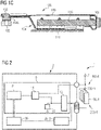
- 2 shows a first embodiment of a circuit arrangement 1.
- the circuit arrangement 1 is together with several SMA elements 100-1 to 100-N, in particular SMA wires, which in particular as in the Figure 1B and Figure 1C shown are each part of an actuator 103 and thus of a valve 120 designed to control a plurality of valves 120 of a seat comfort system 2 .
- the circuit arrangement 1 comprises a measuring device 5 and a control unit 30.
- the measuring device 5 can be connected or is connected to each of the SMA elements 100-1 to 100-N.
- the measuring device 5 forms an air mass measuring device 305-1 to 305-N with each of the SMA elements 100-1 to 100-N.
- the measuring device 5 can be designed as a resistance measuring device, a temperature measuring device, a current measuring device and/or a power measuring device.
- the SMA elements 100-1 to 100-N are connected to a voltage source U represented by the arrow.
- the control unit 30 is connectable or permanently connected to each of the SMA elements 100 - 1 to 100 -N via SMA drivers 20 .
- the SMA drivers 20 are arranged in a driver unit 6 .
- the measuring device 5 generates an output signal, which is transmitted by cable or wirelessly to the control unit 30 and is used there as an input signal for controlling or regulating the SMA driver 20 .
- the measuring device 5 optionally includes a multiplexer 12, which can be connected or is connected to each of the SMA elements 100-1 to 100-N, so that in particular by applying a measuring current using a current source 13, a resistance of one of the SMA elements 100-1 to 100-N is measured. Furthermore, a signal amplifier 14 is expediently provided in the measuring device 5, which can have an offset correction. The measurement signal obtained can now be evaluated in an evaluation unit 8 to determine the air mass. In the example shown, the evaluation unit 8 is arranged in the measuring device 5 . Alternatively, it can be arranged as a separate component between measuring device 5 and control unit 30 .
- the control unit 30 in 2 The circuit arrangement 1 shown can be designed for actuating the SMA elements 100-1 to 100-N by means of pulse width modulation.
- 3 12 shows an alternative embodiment of a valve 120.
- a wire 140 separate from the SMA element 100 is arranged as a measuring wire at various positions in the valve 120 .
- 3 12 shows three different positions at which the wire 140 can be arranged as examples.
- the wire 140 can be arranged as a wire 141 in the second opening 106 and/or as a wire 142 in the first opening 105 of the valve 120 .
- the wire 140 can be arranged as a wire 143 in a valve chamber, for example a flow chamber of the valve.
- wire 140 in particular wire 141 and/or wire 142 and/or wire 143, can alternatively or additionally be connected to measuring device 5 (see, for example, 4 ) be connectable or connected and together with the measuring device 5 each form an air mass measuring device.
- FIG 4 shows a second embodiment of the circuit arrangement 1, in which separate wires 140-1 to 140-M are additionally arranged in the respective valves 120, as for example in FIG 3 shown, which, like the SMA elements 100-1 to 100-N, each form an air mass measuring device 305-X with the measuring device 5, so that the air mass measurement can also be carried out on the wires 140-1 to 140-M and the control of the respective SMA element 100-1 to 100-N of the respective valve 120 via the SMA driver 20 based on this measurement.
- the separate wires 140-1 to 140-M are in the in 4
- the embodiment shown is connected in parallel with the SMA elements 100-1 to 100-N, however the separate wires 140-1 to 140-M for the measurement can each be driven separately for the respective measurement.
- a resistance for example, can also be measured at the SMA elements 100 - 1 to 100 -N by means of the circuit arrangement 1 .
- the number M of separate wires 140-1 to 140-M and the number N of SMA elements 100-1 to 100-N can be the same or different. If the actuator 103 of the valve 120 controls the actuating element 104 with a piezoelectric element or a magnetic, in particular electromagnetic element, as an alternative to an SMA element, this piezoelectric or magnetic element can be used analogously to the 4 SMA elements 100-1 to 100-N shown are controlled on the basis of the respective measured values of the air mass measurement with the respective wire 140-1 to 140-M.
- FIG figure 5 shows a third embodiment of a circuit arrangement 1.
- the circuit arrangement 1 differs from that in 2 Circuit arrangement 1 shown by the series resistors 21-1 to 21-N, which are each connected before the SMA elements 100-1 to 100-N.
- Optional are also here, as in 4 shown, in addition to the SMA elements 100-1 to 100-N, separate wires 140-1 to 140-M are arranged as in FIG figure 5 shown, before each of which a series resistor 23-1 to 23-M is also connected.
- the series resistors 21-1 to 21-N and the series resistors 23-1 to 23-M thus each supplement the respective air mass measuring device 305-X.
- circuit arrangement 1 differs according to figure 5 of the circuit arrangement 1 after 2 in that a filter 16 is arranged in addition to the amplifier 14 in the measuring device 5 .
- a filter 16 is arranged in addition to the amplifier 14 in the measuring device 5 .
- several filter and amplifier stages and/or integration elements which serve to improve the signal, can also be used.
- the evaluation unit 8 comprises according to FIG figure 5 a memory 36.
- An external memory, which the evaluation unit 8 can access, is also possible as an alternative or in addition.
- the control unit 30 includes in addition to the in figure 5 shown input 31, which may also be present in the other configurations and for example Input of a control signal, which can be transmitted wirelessly or wired, can be formed, a pulse width modulation device 60, which is connected to the driver unit 6 and thus the SMA drivers 20-1 to 20-N.
- the control unit 30 can be designed to control the measuring device 5 .
- separate wires 140-1 to 140-M can also be integrated into the circuit arrangement 1 in a simple manner.
- FIG. 6 shows an ASIC 4 that can be used to implement the circuit arrangement 1 according to the invention.
- This ASIC 4 can include the components of the measuring device 5, for example the evaluation unit 8 and/or the memory 36 and/or the amplifier 14 and/or the filter 16.
- the ASIC 4 can include the control unit 30, for example with the pulse width modulation device 60.
- the ASIC 4 can in particular also include the input 31, designed for example for the input of a control signal, which can be transmitted wirelessly or by cable.
- the ASIC 4 can also include the driver unit 6 with the SMA drivers 20 .
- FIG. 7 shows a valve arrangement 200 of a seat comfort system 2 with a plurality of valves, specifically first valves 120a and second valves 120b, which are controlled with a circuit arrangement 1 according to the invention.
- the view shows a section of an intermediate housing 208 of the seat comfort system 2.
- a common pressure connection 270 which can be connected to a pneumatic pump
- a first flow area 282 which is assigned to the first valves 120a, in this case four valves 120a, is supplied via one of the intermediate housing 208 formed air channel 276 supplied air (indicated by dashed arrows).
- a check valve 272 is arranged within the air channel 276 between the pressure connection 270 and the first flow area 282 .
- Second valves 120b in this case four second valves 120b, are connected via a second flow area 274 to a common opening to the atmosphere (not shown).
- a valve 120a and a valve 120b are each connected to one another via an air duct 278a, 278b, 278c, 278d.
- Air cushions can be connected to consumer connections 230a, 230b, 230c, 230d. If an air cushion is deflated, the air contained therein first flows via the respective consumer connection 230a, 230b, 230c, 230d into the respectively assigned air duct 278a, 278b, 278c, 278d and then via the assigned, opened second valve 120b into the second flow area 274 and from there there to the atmosphere.
- the corresponding first valve 120a which is connected to the same air duct 278a, 278b, 278c, 278d, is closed in this case.
- a first valve 120a and a second valve 120b are assigned to and connected to an air cushion or, in general, an air reservoir, with the first valve 120a serving to fill the air cushion with air and the second valve 120b serving to empty the air cushion.
- the SMA elements, in particular SMA wires, of the valves 120a, 120b can be used as the measuring wire of the air mass measuring device and on the other hand separate wires 140 can be used as the measuring wire of the air mass measuring device.
- the arrangement is in an area exclusively assigned to the respective valve 120a, 120b, as in FIG 3 shown as an example, possible.
- a wire 140 can also be placed in a common air duct 276, in 7 additionally denoted by the reference number 144, and/or in the common pressure port 270, in 7 additionally denoted by the reference numeral 145, and/or in the second flow region 274, in 7 additionally marked by reference numeral 146.
- the seat comfort system 2 comprises a valve 120 which has a first valve opening 310, a second valve opening 311 and a third valve opening 312.
- the first valve port 310 is connected to a pump 300 via a fluid line 320 .
- the second valve opening 311 is connected to an air cushion 330 via a fluid line 321 .
- the third valve port 312 is connected to an atmosphere port 340 via another fluid line 322 .
- Components of one or more air mass measuring devices in particular the measuring wires of the air mass measuring devices, can be arranged in one or more of the fluid lines 320, 321, 322.
- the air mass measuring device assigned to fluid line 320 is denoted by reference number 305a, the air mass measuring device assigned to fluid line 322 by reference number 305b and the air mass measuring device assigned to fluid line 321 by reference number 305d.
- the measuring wire of an air mass measuring device can also be arranged in the valve 120 itself.
- this air mass measuring device is symbolically denoted by reference numeral 305c.
- the plurality of air cushions 330 can be connected to one or more valves 120 .
- a plurality of air cushions 330 are connected to a valve arrangement 200, a valve arrangement 200, for example a valve arrangement according to FIG 7 , essentially the in 8 valve 120 shown would replace, and instead of the one air bag 330 shown, several air bags 330 would be connected in parallel to the valve assembly 200.
- the air mass measuring devices in particular the measuring wires of the air mass measuring devices, can then be arranged accordingly in the valve arrangement 200 and/or the respective air ducts and/or flow areas and/or fluid lines.
Abstract
Die Erfindung betrifft ein Ventil (120) mit einem Ventilgehäuse (102),wobei das Ventilgehäuse (102) zumindest eine erste Öffnung (105) und zumindest eine zweite Öffnung (106) aufweist,wobei das Ventilgehäuse (102) einen Ventilraum (109) umschließt,wobei das Ventil (120) einen Aktuator (103) mit einem Stellelement (104) umfasst,wobei das Stellelement (104) zum Öffnen oder Schließen des Ventils (120) angeordnet ist.Das erfindungsgemäße Ventil (120) ist dadurch gekennzeichnet, dass das Ventil (120) zumindest eine Luftmassenmessvorrichtung zur Messung einer das Ventil (120) durchströmenden Luftmasse oder zumindest einen Messdraht (100) einer Luftmassenmessvorrichtung zur Messung einer das Ventil (120) durchströmenden Luftmasse umfasst.Weiterhin betrifft die Erfindung eine Ventilanordnung und ein Sitzkomfortsystem.The invention relates to a valve (120) with a valve housing (102), the valve housing (102) having at least one first opening (105) and at least one second opening (106), the valve housing (102) enclosing a valve chamber (109). ,wherein the valve (120) comprises an actuator (103) with an actuating element (104),wherein the actuating element (104) is arranged for opening or closing the valve (120).The valve (120) according to the invention is characterized in that the Valve (120) comprises at least one air mass measuring device for measuring an air mass flowing through the valve (120) or at least one measuring wire (100) of an air mass measuring device for measuring an air mass flowing through the valve (120). The invention also relates to a valve arrangement and a seat comfort system.
Description
Die Erfindung betrifft ein Ventil, insbesondere ein Ventil eines Sitzkomfortsystems. Die Erfindung betrifft ferner eine Ventilanordnung und ein Sitzkomfortsystem.The invention relates to a valve, in particular a valve of a seat comfort system. The invention also relates to a valve arrangement and a seat comfort system.
Nach dem Stand der Technik ist zum Beispiel aus der
Ein Sitzkomfortsystem ist ein System für eine Sitzkomfortfunktion eines Sitzes, beispielsweise eines Fahrzeugsitzes. Beispielsweise kann ein derartiges Sitzkomfortsystemmit eine pneumatische Lordosenstützvorrichtung und/oder eine Massagevorrichtung für einen Sitz umfassen. Ein Sitzkomfortsystem umfasst typischerweise eine Mehrzahl von Luftkissen, welche gefüllt und mit einem gewünschten, gegebenenfalls zeitlich veränderten Druck beaufschlagt werden können. Dazu umfasst das Sitzkomfortsystem eine Steuereinheit, eine Pumpe zum Beaufschlagen der Luftkissen mit Druckluft und eine Mehrzahl von Ventilen, wobei zweckmäßigerweise jedem Luftkissen zumindest ein Ventil zugeordnet ist. Jedes dieser Ventile kann einen Aktuator mit einem SMA-Element (SMA: shape memory alloy - Formgedächtnislegierung), also einem aus einer Formgedächtnislegierung bestehenden Element umfassen, welches je nach Bestromung das Ventil in einen geöffneten, teilgeöffneten oder geschlossenen Funktionszustand versetzt. Üblicherweise handelt es sich bei dem SMA-Element um einen SMA-Draht. Die zugeführte Leistung muss üblicherweise in einem sehr eng definierten Bereich gehalten werden, um eine zuverlässige Aktivierung des Aktuators zu gewährleisten und dennoch eine thermische Überlastung und somit eine dauerhafte Schädigung des SMA-Elementes zu vermeiden. Somit sind der Steuereinheit zweckmäßigerweise Sensoren zur Strom-, Spannungs- und/oder Temperaturüberwachung zugeordnet.A seat comfort system is a system for a seat comfort function of a seat, for example a vehicle seat. For example, such a seat comfort system can include a pneumatic lumbar support device and/or a massage device for a seat. A seat comfort system typically includes a plurality of air cushions, which can be filled and subjected to a desired pressure, which may vary over time. For this purpose, the seat comfort system comprises a control unit, a pump for applying compressed air to the air cushions and a plurality of valves, with at least one valve being expediently assigned to each air cushion. Each of these valves can include an actuator with an SMA element (SMA: shape memory alloy), ie an element made of a shape memory alloy, which, depending on the current supply, puts the valve in an open, partially open or closed functional state. Typically, the SMA element is an SMA wire. The power supplied must usually be in must be kept in a very narrowly defined range in order to ensure reliable activation of the actuator while still avoiding thermal overload and thus permanent damage to the SMA element. Sensors for current, voltage and/or temperature monitoring are therefore expediently assigned to the control unit.
Aus der
Alternativ zu dem in
Die in
Aus der
Aus der
Aus der
Die bekannten Verfahren beruhen darauf, dass jeweils bei einer bestimmten Position des Stellelements eine Art Schalter betätigt wird, der durch einen Kippschalter oder eine Überbrückung realisiert ist. Solche mechanischen Schalter können durch Schmutzpartikel, Abrieb, Flüssigkeiten aber auch eine hohe Schaltfrequenz in ihrer Funktion beeinträchtigt werden.The known methods are based on the fact that a type of switch, which is realized by a toggle switch or a bypass, is actuated in each case at a specific position of the actuating element. Such mechanical switches can be impaired in their function by dirt particles, abrasion, liquids, but also a high switching frequency.
Aufgabe der Erfindung ist es, ein neues Ventil, insbesondere eine gegenüber dem Stand der Technik verbessertes Ventil anzugeben. Weitere Aufgabe ist es, eine Ventilanordnung und ein Sitzkomfortsystem mit derartigen Ventilen anzugeben.The object of the invention is to specify a new valve, in particular a valve which is improved over the prior art. A further object is to specify a valve arrangement and a seat comfort system with such valves.
Diese Aufgabe wird hinsichtlich des Ventils durch ein Ventil mit den Merkmalen des Anspruchs 1, hinsichtlich der Ventilanordnung durch eine Ventilanordnung mit den Merkmalen des Anspruchs 9 und hinsichtlich des Sitzkomfortsystems durch ein Sitzkomfortsystem mit den Merkmalen des Anspruchs 11 gelöst. Zweckdienliche Ausgestaltungen ergeben sich aus den jeweiligen Unteransprüchen.This object is achieved with regard to the valve by a valve having the features of claim 1, with regard to the valve arrangement by a valve arrangement with the features of claim 9 and with regard to the seat comfort system by a seat comfort system with the features of claim 11. Appropriate configurations result from the respective dependent claims.
Das erfindungsgemäße Ventil ist beispielsweise ein Ventil eines Sitzkomfortsystems. Das Sitzkomfortsystem kann ein oder mehrere Ventile umfassen. Das Sitzkomfortsystem kann beispielsweise in einen Fahrzeugsitz eingesetzt werden oder eingesetzt sein. Bei dem Sitzkomfortsystem kann es sich beispielsweise um eine Lordosenstützvorrichtung und/oder Massageeinrichtung handeln. Typischerweise umfasst das Sitzkomfortsystem ein oder mehrere Luftkissen, die üblicherweise in einem Sitz, insbesondere einem Fahrzeugsitz, angeordnet sind.The valve according to the invention is, for example, a valve of a seat comfort system. The seat comfort system can include one or more valves. The seat comfort system can be used or used in a vehicle seat, for example. The seat comfort system can be, for example, a lumbar support device and/or massage device. The seat comfort system typically includes one or more air cushions, which are usually arranged in a seat, in particular a vehicle seat.
Das erfindungsgemäße Ventil umfasst ein Ventilgehäuse, wobei das Ventilgehäuse beispielsweise einen Gehäusedeckel, einen Gehäuseboden und ein zwischen dem Gehäusedeckel und dem Gehäuseboden angeordnetes Zwischengehäuse aufweisen kann. Das Ventilgehäuse weist zumindest eine erste Öffnung und zumindest eine zweite Öffnung aufweist und das Ventilgehäuse umschließt einen Ventilraum. Dieser kann eine Strömungskammer und eine Betätigungskammer umfassen. Das Ventil umfasst einen Aktuator mit einem Stellelement zum Öffnen oder Schließen des Ventils, beispielsweise der ersten und/oder zweiten Öffnung oder einer Öffnung innerhalb des Ventils, beispielsweise einer Öffnung zwischen der Strömungs- und der Betätigungskammer, sowie zweckmäßigerweise ein Rückstellelement. Insbesondere ist das Stellelement zumindest zwischen einer ersten Stellung und einer zweiten Stellung verstellbar. Erste Stellung und zweite Stellung sind im Sinne dieser Anmeldung zwei voneinander verschiedene Stellungen, die als Öffnungs- und Schließstellung des Ventils oder als Zwischenstellungen gewählt werden können. Der Aktuator kann beispielsweise ein piezoelektrisches Element oder ein magnetisches Element, insbesondere ein elektromagnetisches Element, oder ein SMA-Element (Formgedächtnislegierungs-Element) umfassen.The valve according to the invention comprises a valve housing, wherein the valve housing can have, for example, a housing cover, a housing base and an intermediate housing arranged between the housing cover and the housing base. The valve housing has at least one first opening and at least one second opening, and the valve housing encloses a valve chamber. This may include a flow chamber and an actuation chamber. The valve comprises an actuator with an actuating element for opening or closing the valve, for example the first and/or second opening or an opening within the valve, for example an opening between the flow and the actuation chamber, and expediently a restoring element. In particular, the actuating element can be adjusted at least between a first position and a second position. For the purposes of this application, the first position and second position are two positions that are different from one another and can be selected as the open and closed position of the valve or as intermediate positions. The actuator can, for example, comprise a piezoelectric element or a magnetic element, in particular an electromagnetic element, or an SMA element (shape memory alloy element).
Das erfindungsgemäße Ventil umfasst zumindest eine Luftmassenmessvorrichtung zur Messung einer das Ventil durchströmenden Luftmasse oder zumindest einen Messdraht einer Luftmassenmessvorrichtung zur Messung einer das Ventil durchströmenden Luftmasse.The valve according to the invention comprises at least one air mass measuring device for measuring an air mass flowing through the valve or at least one measuring wire of an air mass measuring device for measuring an air mass flowing through the valve.
Die durch das Ventil strömende Luftmasse kann beispielsweise, wie untenstehend näher erläutert wird, mittels eines Messdrahtes bestimmt werden, an dem die zu messende Luftmasse vorbeiströmt und hierbei beispielsweise eine Temperaturänderung an oder in der Umgebung des Messdrahtes hervorruft. Anhand der das Ventil durchströmenden Luftmasse kann somit bestimmt oder zumindest abgeschätzt werden, wieviel Luft bzw. welche Luftmenge sich in einem zugeordneten Luftkissen beispielsweise des Sitzkomfortsystems befindet. Beispielsweise können hierzu die Messwerte der Luftmassenmessvorrichtung mit hinterlegten Vergleichswerten verglichen und/oder parallel Referenzmessungen in Bereichen vorgenommen werden, an denen keine Luftströmung vorhanden ist, beispielsweise an zusätzlichen Referenzmessdrähten.The air mass flowing through the valve can be determined, for example, as explained in more detail below, by means of a measuring wire, past which the air mass to be measured flows, causing a temperature change on or in the vicinity of the measuring wire. The air mass flowing through the valve can thus be used to determine or at least estimate how much air or what quantity of air is in an associated air cushion, for example of the seat comfort system. For example, the measured values of the air mass measuring device can be compared with stored comparison values and/or parallel reference measurements can be made in areas where there is no air flow, for example on additional reference measuring wires.
Ein Vorteil der Erfindung liegt somit darin, dass mittels des Ventils die Luftmasse und somit die Menge der Luft bestimmt werden kann, die das Ventil durchströmt. Anhand der das Ventil durchströmenden Luftmasse kann daher bestimmt oder zumindest abgeschätzt werden, wieviel Luft sich beispielsweise in einem zugeordneten Luftkissen, beispielsweise eines Sitzkomfortsystems, befindet.One advantage of the invention is that the air mass and thus the amount of air flowing through the valve can be determined by means of the valve. Based on the air mass flowing through the valve, it can therefore be determined or at least estimated how much air is, for example, in an assigned air cushion, for example a seat comfort system.
Die Luftmassenmessvorrichtung kann zumindest einen Messdraht umfassen, wobei der Messdraht innerhalb des Ventilgehäuses und/oder im Ventilraum und/oder in der ersten Öffnung und/oder in der zweiten Öffnung angeordnet ist. Beispielsweise kann der Messdraht in der Strömungskammer des Ventils angeordnet sein.The air mass measuring device can include at least one measuring wire, the measuring wire being arranged within the valve housing and/or in the valve chamber and/or in the first opening and/or in the second opening. For example, the measuring wire can be arranged in the flow chamber of the valve.
Weiter kann die Luftmassenmessvorrichtung eine Messvorrichtung zum Messen physikalischer Größen des Messdrahts umfassen. Die Messvorrichtung wiederum kann beispielsweise
- a. eine Widerstandsmessvorrichtung zur Messung des Widerstands des Messdrahtes und/oder
- b. einen Temperatursensor und/oder eine Temperaturmessvorrichtung zur Messung einer Temperatur des Messdrahtes und/oder der Umgebungstemperatur des Messdrahtes und/oder
- c. eine Strommessvorrichtung zur Messung eines Heizstroms des Messdrahtes und/oder
- d. eine Leistungsmessvorrichtung zur Messung einer Eingangsleistung des Messdrahtes umfassen.
- a. a resistance measuring device for measuring the resistance of the measuring wire and/or
- b. a temperature sensor and/or a temperature measuring device for measuring a temperature of the measuring wire and/or the ambient temperature of the measuring wire and/or
- c. a current measuring device for measuring a heating current of the measuring wire and/or
- i.e. comprise a power measuring device for measuring an input power of the measuring wire.
Die Änderung der Messwerte, die mittels der Messvorrichtung festgestellt wird, ist abhängig von der dem Messdraht entzogenen Wärmemenge durch die vorbeistreichende Luft und somit ein Indikator für die zu bestimmende Luftmasse. Im Sinne dieser Erfindung soll unter Widerstand der elektrische Widerstand verstanden werden.The change in the measured values, which is determined by means of the measuring device, depends on the amount of heat withdrawn from the measuring wire by the air passing by and is therefore an indicator for the air mass to be determined. For the purposes of this invention, resistance should be understood to mean electrical resistance.
Gemäß einer Weiterbildung ist die Messvorrichtung Teil einer Schaltungsanordnung zur Ansteuerung des Ventils, wobei die Schaltungsanordnung zumindest eine Treibereinheit zum Betätigen des Aktuators und eine Steuereinheit zum Steuern der Treibereinheit aufweist, und wobei die Steuereinheit dazu geeignet ist, ein Ausgangssignal der Messvorrichtung der Luftmassenmessvorrichtung zu verarbeiten.According to one development, the measuring device is part of a circuit arrangement for controlling the valve, the circuit arrangement having at least one driver unit for actuating the actuator and a control unit for controlling the driver unit, and the control unit being suitable for processing an output signal of the measuring device of the air mass measuring device.
Die Steuereinheit ist somit derart eingerichtet, dass sie ein Ausgangssignal und damit ein Messergebnis der Luftmassenmessvorrichtung verarbeitet und dieses Messergebnis somit beispielsweise zum Steuern der Treibereinheit zum Betätigen des Aktuators verwendet, also beispielsweise beim Erreichen eines vorgegebenen Schwellenwertes der durchströmenden Luftmasse bzw. Luftmenge das Ventil schließt. Das erfindungsgemäße Ventil ermöglicht somit beispielsweise beim Füllen oder Entleeren von Luftkissen die, insbesondere kontaktlose, Erkennung eines oder mehrerer vorgegebener Füllzustände des Luftkissens und kann das Ventil entsprechend steuern oder regeln, beispielsweise das Ventil schließen oder öffnen.The control unit is thus set up in such a way that it processes an output signal and thus a measurement result of the air mass measuring device and thus uses this measurement result, for example, to control the driver unit to actuate the actuator, i.e. for example to close the valve when a predetermined threshold value of the air mass or air quantity flowing through is reached. The valve according to the invention thus enables, for example, when filling or emptying air cushions, in particular contactless, detection of one or more predetermined filling states of the air cushion and can control or regulate the valve accordingly, for example closing or opening the valve.
Die Luftmassenmessvorrichtung erzeugt also, beispielsweise basierend auf der Messung von Temperatur und/oder Heizstrom und/oder elektrischer Leistungsaufnahme und/oder Widerstand mindestens eines Messdrahtes der Luftmassenmessvorrichtung und/oder der Veränderung dieser Messgrößen mit der Zeit, ein Ausgangssignal, das die durch das Ventil geströmte Luftmasse und damit auch die Luftmenge kennzeichnet. Dieses Ausgangssignal wird an die Steuereinheit weitergegeben, so dass die Steuereinheit beispielsweise die Treibereinheit basierend auf der gemessenen Luftmasse bzw. Luftmenge steuern oder regeln kann.The air mass measuring device therefore generates, for example based on the measurement of temperature and/or heating current and/or electrical power consumption and/or resistance of at least one measuring wire of the air mass measuring device and/or the change in these measured variables over time, an output signal that the flowed through the valve Air mass and thus also the air volume characterizes. This output signal is forwarded to the control unit, so that the control unit can, for example, control or regulate the driver unit based on the measured air mass or air quantity.
Das Ausgangssignal der jeweiligen, vorstehend erläuterten Messvorrichtung wird an die Steuereinheit weitergegeben, sodass die Steuereinheit die Treibereinheit basierend auf dem gemessenen Wert der Messvorrichtung steuern oder regeln kann. Die Schaltungsanordnung kann dazu ausgelegt sein, dass entweder der Widerstand, der Strom und/oder die Leistung des Messdrahtes gemessen wird oder eine Bestromung erfolgt, somit also Messvorrichtung und Treibereinheit alternierend mit dem Messdraht wirkverbunden werden, was insbesondere dann zweckmäßig ist, wenn der Messdraht ein SMA-Element, also ein SMA-Draht ist, der gleichzeitig ein Element des Aktuators des Ventils ist. Dies wird nachfolgend näher erläutert. Im Falle einer Temperaturmessung können ebenfalls Messung und Ansteuerung der Treibereinheit gleichzeitig oder alternierend erfolgen. Es kann vorgesehen sein, dass die Steuereinheit auch die Widerstandsmessvorrichtung und/oder den Temperatursensor und/oder die Temperaturmessvorrichtung und/oder die Strommessvorrichtung und/oder die Leistungsmessvorrichtung steuert.The output signal of the respective measuring device explained above is forwarded to the control unit, so that the control unit can control or regulate the driver unit based on the measured value of the measuring device. The circuit arrangement can be designed so that either the resistance, the current and/or the power of the measuring wire is measured or current is applied, i.e. the measuring device and driver unit are alternately actively connected to the measuring wire, which is particularly useful when the measuring wire is SMA element, i.e. an SMA wire, which is also an element of the valve actuator. This is explained in more detail below. In the case of a temperature measurement, the driver unit can also be measured and controlled simultaneously or alternately. It can be provided that the control unit also controls the resistance measuring device and/or the temperature sensor and/or the temperature measuring device and/or the current measuring device and/or the power measuring device.
Eine Ausgestaltung sieht vor, dass der Aktuator des Ventils ein SMA-Element aufweist. Beispielsweise kann es sich hierbei um einen SMA-Draht handeln, worunter ein drahtförmiges aber auch ein bandförmiges SMA-Element verstanden wird. Der SMA-Draht kann dann der Messdraht oder einer der Messdrähte der Luftmassenmessvorrichtung sein. Gegebenenfalls können ein oder mehrere weitere Messdrähte der Luftmassenmessvorrichtung vorgesehen sein. Eine Weiterbildung dieser Ausgestaltung sieht vor, dass die Luftmassenmessvorrichtung eine Messvorrichtung, insbesondere eine Widerstandsmessvorrichtung, umfasst und dass die Schaltungsanordnung dazu ausgelegt ist, dass die Messvorrichtung und die Treibereinheit alternierend mit dem SMA-Element, konkret dem SMA-Draht, wirkverbunden sind. Diese alternierende Ansteuerung kann durch die entsprechend eingerichtete Steuereinheit verwirklicht sein. Es wird somit entweder die Luftmasse mit dem SMA-Draht in seiner Funktion als Messdraht gemessen oder es erfolgt eine Bestromung des SMA-Drahts in seiner Funktion als Aktuator. Diese beiden Funktionen werden alternierend durchgeführt, das heißt Luftmassenmessvorrichtung und Treibereinheit werden alternierend mit dem SMA-Draht wirkverbunden. Dazu kann insbesondere die Steuereinheit neben der Treibereinheit auch die Luftmassenmessvorrichtung steuern.One embodiment provides that the actuator of the valve has an SMA element. For example, this can be an SMA wire, which is understood to mean a wire-shaped but also a strip-shaped SMA element. The SMA wire can then be the measuring wire or one of the measuring wires of the air mass measuring device. If necessary, one or more additional measuring wires of the air mass measuring device can be provided. A further development of this design provides that the air mass measuring device comprises a measuring device, in particular a resistance measuring device, and that the circuit arrangement is designed such that the measuring device and the driver unit are operatively connected alternately to the SMA element, specifically the SMA wire. This alternating control can be implemented by the appropriately set up control unit. Thus, either the air mass is measured with the SMA wire in its function as a measuring wire, or the SMA wire is energized in its function as an actuator. These two functions are performed alternately, that is to say the air-mass measuring device and driver unit are actively connected alternately to the SMA wire. For this purpose, in particular, the control unit can also control the air mass measuring device in addition to the driver unit.
Zusätzlich zum SMA-Element kann auch zumindest ein separater Draht, also ein zusätzlich zum SMA-Element vorgesehener Draht, vorgesehen sein, wobei der separate Draht der Messdraht oder einer der Messdrähte der Luftmassenmessvorrichtung ist. Gegebenenfalls können ein oder mehrere weitere Messdrähte der Luftmassenmessvorrichtung vorgesehen sein, wobei auch das SMA-Element ein SMA-Draht sein kann, der als weiterer Messdraht vorgesehen ist.In addition to the SMA element, at least one separate wire, that is to say a wire provided in addition to the SMA element, can also be provided, with the separate wire being the measuring wire or one of the measuring wires of the air mass measuring device. If necessary, one or more additional measuring wires of the air mass measuring device can be provided, in which case the SMA element can also be an SMA wire, which is provided as an additional measuring wire.
Der separate Draht ist somit getrennt vom SMA-Element des Aktuators angeordnet. Bei diesem separaten Draht kann es sich um einen Draht aus einem SMA-Material oder aus einem anderen metallischen Material, z.B. Wolfram oder Platin, oder aus einer Legierung handeln. Der separate Draht kann beispielsweise parallel zu dem oder den SMA-Elementen geschaltet sein, aber davon verschieden, also getrennt von diesen SMA-Elementen, angesteuert werden.The separate wire is thus arranged separately from the SMA element of the actuator. This separate wire can be a wire made from an SMA material or from another metallic material, such as tungsten or platinum, or from an alloy. The separate wire can, for example, be connected in parallel to the SMA element or elements, but can be controlled differently, that is to say separately from these SMA elements.
Das Ventil kann in Ausgestaltung über weitere Sensoren zur Strom-, Spannungs- und/oder Temperaturüberwachung verfügen. Das Ventil, insbesondere die Steuereinheit, kann in Ausgestaltung über Kommunikationsschnittstellen verfügen, um über in einem Fahrzeug vorhandene Schalter und/oder einen Bordcomputer gesteuert zu werden. Als weiteren Eingang kann das Ventil, insbesondere die Steuereinheit, über eine LIN (Local Interconnect Network)-Kommunikationsschnittstelle verfügen, welche insbesondere einen Sendeempfänger und/oder eine Schaltereingangsschnittstelle aufweist. Die Schaltereingangsschnittstelle ist insbesondere zum Verarbeiten widerstandsbasierter Schaltersignale geeignet, wobei die Schaltereingangsschnittstelle für eine Mehrzahl von Schaltereingängen ausgelegt sein kann, z.B. für die Sitzverstellung, insbesondere die Sitzposition, und für Lordose- und/oder Massagefunktionen. Die Steuereinheit kann einen Speicher zum Speichern von Daten umfassen.In one embodiment, the valve can have additional sensors for current, voltage and/or temperature monitoring. In one embodiment, the valve, in particular the control unit, can have communication interfaces in order to be controlled by switches and/or an on-board computer that are present in a vehicle. As a further input, the valve, in particular the control unit, have a LIN (Local Interconnect Network) communication interface, which in particular has a transceiver and/or a switch input interface. The switch input interface is particularly suitable for processing resistance-based switch signals, it being possible for the switch input interface to be designed for a plurality of switch inputs, eg for seat adjustment, in particular the seat position, and for lordosis and/or massage functions. The control unit may include memory for storing data.
Das Ventilgehäuse kann zumindest eine, beispielsweise von der Strömungskammer in die Betätigungskammer mündende Ventilöffnung aufweisen, wobei innerhalb der Betätigungskammer das zwischen einer Schließstellung zum Verschließen der Ventilöffnung und einer Öffnungsstellung zur Freigabe der Ventilöffnung axial bewegbare Stellelement, ein zur Betätigung des Stellelementes in Öffnungsrichtung dienendes draht- oder bandförmiges SMA-Element aus einer Formgedächtnislegierung, ein zur Bewegung des Stellelementes in Schließrichtung dienendes Rückstellelement und eine Leiterplatte angeordnet sind, wobei das SMA-Element mit einem Abschnitt an dem Stellelement fixiert und zur Beaufschlagung mit Strom mit zumindest einem Ende mit der Leiterplatte elektrisch verbunden ist.The valve housing can have at least one valve opening, for example opening from the flow chamber into the actuating chamber, wherein the actuating element, which can be moved axially between a closed position for closing the valve opening and an open position for releasing the valve opening, has a wire inside the actuating chamber for actuating the actuating element in the opening direction. or strip-shaped SMA element made of a shape memory alloy, a restoring element serving to move the actuating element in the closing direction, and a printed circuit board are arranged, with one section of the SMA element being fixed to the actuating element and electrically connected at least one end to the printed circuit board for the application of current is.
In zweckmäßiger Ausgestaltung ist das SMA-Element mit einem mittleren Abschnitt an dem Stellelement fixiert und mit beiden Enden mit der Leiterplatte verbunden.In an expedient refinement, the SMA element is fixed to the actuating element with a middle section and is connected to the printed circuit board with both ends.
In weiterer Ausgestaltung sind Luftmassenmessvorrichtung und/oder Steuereinheit dazu eingerichtet, die Luftmasse aus
- a. der Temperatur des Messdrahtes und dem Heizstrom und/oder
- b. der Temperatur des Messdrahtes und der Eingangsleistung und/oder
- c. dem Widerstand des Messdrahtes und dem Heizstrom und/oder
- d. dem Widerstand des Messdrahtes und der Eingangsleistung zu ermitteln.
- a. the temperature of the measuring wire and the heating current and/or
- b. the temperature of the measuring wire and the input power and/or
- c. the resistance of the measuring wire and the heating current and/or
- i.e. the resistance of the measuring wire and the input power.
Die vorstehend angesprochene Schaltungsanordnung zur Ansteuerung des Ventils, insbesondere die Messvorrichtung, kann eine Auswerteeinheit umfassen oder mit einer Auswerteeinheit verbunden sein. Die Auswerteeinheit kann beispielsweise konkrete Messwerte der Luftmassenmessvorrichtung, beispielsweise Widerstandsmesswerte, Temperaturwerte, Stromstärken und/oder Leistungswerte, aufnehmen und auswerten und hieraus ein Ausgangssignal erzeugen, das an die Steuereinheit weitergebenen wird. Dieses Ausgangssignal kann insbesondere ein Signal zur Übermittlung des Erreichens einer Endbedingung umfassen.The above-mentioned circuit arrangement for controlling the valve, in particular the measuring device, can include an evaluation unit or be connected to an evaluation unit. The evaluation unit can, for example, record and evaluate specific measured values of the air mass measuring device, for example measured resistance values, temperature values, current strengths and/or power values, and generate an output signal therefrom that is forwarded to the control unit. This output signal can in particular include a signal for communicating that an end condition has been reached.
In einer Ausgestaltung umfasst die Schaltungsanordnung einen ASIC (ASIC: application-specific integrated circuit - anwendungsspezifische integrierte Schaltung), welcher eine oder mehrere der folgenden Komponenten aufweist: die Treibereinheit, insbesondere mit einem oder mehreren SMA-Treibern, eine bzw. die vorstehend genannte Messvorrichtung der Luftmassenmessvorrichtung, insbesondere mit einer Auswerteeinheit und/oder einem Speicher, und die Steuereinheit. Durch die Ausgestaltung mit einem ASIC wird die Schaltungsanordnung kleiner und kann kostengünstiger hergestellt werden. Dabei kann die Messvorrichtung, wie vorstehend ausgeführt, eine Tempermessvorrichtung, Widerstandsmessvorrichtung, Strommessvorrichtung und/oder Leistungsmessvorrichtung sein.In one configuration, the circuit arrangement comprises an ASIC (ASIC: application-specific integrated circuit) which has one or more of the following components: the driver unit, in particular with one or more SMA drivers, one or the aforementioned measuring device the air mass measuring device, in particular with an evaluation unit and/or a memory, and the control unit. The configuration with an ASIC makes the circuit arrangement smaller and can be manufactured more cost-effectively. As explained above, the measuring device can be a temperature measuring device, resistance measuring device, current measuring device and/or power measuring device.
In einer weiteren Ausgestaltung umfasst das Ventil und/oder die Schaltungsanordnung weitere Sensoren, insbesondere einen Endpositionsschalter. Beispielsweise kann ein solcher Endpositionsschalter sowohl als Sicherheitsmaßnahme als auch als Kalibrierhilfe dienen.In a further embodiment, the valve and/or the circuit arrangement includes additional sensors, in particular an end position switch. For example, such an end position switch can serve both as a safety measure and as a calibration aid.
In Ausgestaltung ist die Schaltungsanordnung einer Vielzahl von Ventilen zugeordnet und umfasst somit eine Vielzahl von Aktuatoren, wobei jedem Aktuator eine Treibereinheit, insbesondere eine Treibereinheit mit einem SMA-Treiber, zur Betätigung des jeweiligen Aktuators oder für jeden Aktuator ein SMA-Treiber in einer Treibereinheit zugeordnet ist. Zweckmäßigerweise umfasst die Schaltungsanordnung einen Multiplexer, welcher mit jedem der SMA-Elemente des Aktuators so verbunden ist, dass der Widerstand jedes SMA-Elements einzeln gemessen werden kann. Somit wird mittels des Multiplexers jedes SMA-Element nacheinander mit der Widerstandsmessvorrichtung zum Messen des Widerstands verbunden.In one embodiment, the circuit arrangement is assigned to a large number of valves and thus includes a large number of actuators, with each actuator being assigned a driver unit, in particular a driver unit with an SMA driver, for actuating the respective actuator or an SMA driver in a driver unit for each actuator is. The circuit arrangement expediently comprises a multiplexer which is connected to each of the SMA elements of the actuator in such a way that the resistance of each SMA element can be measured individually. Consequently By means of the multiplexer, each SMA element is sequentially connected to the resistance measuring device for measuring the resistance.
In weiterer Ausgestaltung umfasst die Schaltungsanordnung, beispielsweise die Auswerteeinheit und/oder die Steuereinheit, einen Speicher zum Speichern von Daten. Bei dem Speicher kann es sich alternativ auch um einen gemeinsamen Speicher der Auswerteeinheit und der Steuereinheit handeln.In a further refinement, the circuit arrangement, for example the evaluation unit and/or the control unit, includes a memory for storing data. Alternatively, the memory can also be a shared memory of the evaluation unit and the control unit.
Es kann vorgesehen sein, dass die Auswerteeinheit und/oder die Steuereinheit einen Verlauf nacheinander gemessener Werte, insbesondere Temperaturmesswerte, Strommesswerte, Widerstandswerte oder (Eingangs-)leistungswerte, desselben SMA-Elementes auswertet und/oder Messwerte mit einem oder mehreren vorgegebenen Werten vergleicht.Provision can be made for the evaluation unit and/or the control unit to evaluate a course of successively measured values, in particular measured temperature values, measured current values, resistance values or (input) power values, of the same SMA element and/or compare measured values with one or more specified values.
Die Steuereinheit ist beispielsweise zur Steuerung mittels Pulsweitenmodulation ausgelegt. Dazu umfasst die Steuereinheit beispielsweise eine Pulsweitenmodulationseinheit. Somit werden die SMA-Elemente über die zugeordneten SMA-Treiber der Treibereinheit nacheinander innerhalb eines Duty-Cycles für eine vorgegebene Pulsweite und Pulshöhe bestromt und somit geheizt. Die Pulsweitenmodulationseinheit kann in Ausgestaltung ein Zeitsignal an die Messvorrichtung, beispielsweise eine Widerstandsmessvorrichtung, und/oder die Luftmassenmessvorrichtung ausgeben.The control unit is designed, for example, for control using pulse width modulation. For this purpose, the control unit includes a pulse width modulation unit, for example. Thus, the SMA elements are energized one after the other within a duty cycle for a predetermined pulse width and pulse height via the associated SMA driver of the driver unit and are thus heated. In one embodiment, the pulse width modulation unit can output a time signal to the measuring device, for example a resistance measuring device, and/or the air mass measuring device.
Es kann ferner vorgesehen sein, dass die Schaltungsanordnung, insbesondere die Messvorrichtung und/oder die Auswerteeinheit, einen Signalverstärker und/oder einen Rauschunterdrücker umfassen.Provision can furthermore be made for the circuit arrangement, in particular the measuring device and/or the evaluation unit, to comprise a signal amplifier and/or a noise suppressor.
Die Messvorrichtung, insbesondere die Widerstandsmessvorrichtung, umfasst in einer Ausgestaltung zwei oder mehr Multiplexer, welche jeweils mit einem Teil der SMA-Elemente verbunden sind. Diese Ausgestaltung ist für große Systeme mit einer Vielzahl von SMA-Elemente möglich. Beispielsweise können pro Multiplexer 20 SMA-Elemente vorgesehen sein.In one configuration, the measuring device, in particular the resistance measuring device, comprises two or more multiplexers, which are each connected to a part of the SMA elements. This configuration is possible for large systems with a large number of SMA elements. For example, 20 SMA elements can be provided per multiplexer.
Zweckmäßigerweise ist jeweils zwischen Messvorrichtung, insbesondere Widerstandsmessvorrichtung, und SMA-Element jeweils ein Vorwiderstand seriell geschaltet. Dieser Vorwiderstand dient in Wesentlichen zur Reduktion von Stromspitzen und reduziert somit die Gefahr einer Überlastung der SMA-Elemente.A series resistor is expediently connected in series between the measuring device, in particular the resistance measuring device, and the SMA element. This series resistor essentially serves to reduce current peaks and thus reduces the risk of overloading the SMA elements.
Es kann auch vorgesehen sein, dass das Ventil und/oder die Schaltungsanordnung weitere Sensoren als die vorstehend bereits beschriebenen umfasst, beispielsweise einen Endpositionsschalter.Provision can also be made for the valve and/or the circuit arrangement to include other sensors than those already described above, for example an end position switch.
Ein Verfahren zur Ansteuerung eines erfindungsgemäßen Ventils, insbesondere mittels der vorgenannten Schaltungsanordnung, umfasst die Schritte:
- a. Messen einer Luftmasse,
- b. Nachfolgend Ansteuern des Aktuators, insbesondere eines SMA-Elementes des Aktuators, mittels der Treibereinheit in Abhängigkeit der gemessenen Luftmasse,
- c. Zyklisches Widerholen des Messens und Ansteuerns bis zum Erreichen einer Endbedingung.
- a. measuring an air mass,
- b. Subsequent activation of the actuator, in particular an SMA element of the actuator, by means of the driver unit depending on the measured air mass,
- c. Cyclic repetition of measurement and activation until an end condition is reached.
Die Endbedingung kann beispielsweise das Erreichen eines vorgegebenen Luftmassenwertes und/oder einer vorgegebenen Änderung und/oder eines Füllstands, beispielsweise eines Luftkissens, sein oder umfassen.The end condition can be or include, for example, reaching a specified air mass value and/or a specified change and/or a filling level, for example of an air cushion.
Bei der Erhitzung eines SMA-Elementes, insbesondere indem das SMA-Element von einem Heizstrom durchflossen wird, ändert sich dessen Widerstand. Eine solche Widerstandsänderung ist beispielweise von
Die Endbedingung kann insbesondere für einen Normalbetrieb so gewählt werden, dass das Stellelement in eine Zwischenstellung nahe der Öffnungs- oder Schließstellung gebracht wird, so dass ein Endpunkt des Aktuators mit dem erfindungsgemäßen Verfahren nicht erreicht wird. Dies reduziert die mechanische Belastung der Ventile.In particular for normal operation, the end condition can be selected such that the actuating element is brought into an intermediate position close to the open or closed position, so that an end point of the actuator is not reached with the method according to the invention. This reduces the mechanical stress on the valves.
Zweckmäßigerweise umfasst das Verfahren eine Ansteuerung mittels Pulsweitenmodulation.The method expediently includes activation by means of pulse width modulation.
In Ausgestaltung umfasst das Verfahren zusätzlich mindestens einen der folgenden Schritte, wobei die Luftmassenmessvorrichtung zumindest einen Messdraht umfasst:
- a. Messen eines Widerstands des Messdrahtes und/oder
- b. Messen einer Temperatur und/oder einer Umgebungstemperatur des Messdrahtes und/oder
- c. Messen eines Heizstroms des Messdrahtes und/oder
- d. Messen einer Eingangsleistung des Messdrahtes.
- a. measuring a resistance of the measuring wire and/or
- b. Measuring a temperature and/or an ambient temperature of the measuring wire and/or
- c. measuring a heating current of the measuring wire and/or
- i.e. measuring an input power of the measuring wire.
Auch kann das Verfahren das Messen des Widerstands aller SMA-Elemente umfassen, wobei die Messung des Widerstands aller SMA-Elemente in einer gemeinsamen Ansteuerungstotzeit erfolgt oder wobei die Messung eines SMA-Elementes jeweils zwischen der Ansteuerung eines SMA-Elementes und der Ansteuerung eines anderen, insbesondere des nachfolgenden SMA-Elementes erfolgt. In diesem Fall sind der Schaltungsanordnung zwei oder mehrere Ventile zugeordnet und entsprechend zwei oder mehrere Aktuatoren vorgesehen, die jeweils ein SMA-Element umfassen.The method can also include measuring the resistance of all SMA elements, with the resistance of all SMA elements being measured in a common activation dead time, or with the measurement of an SMA element taking place between the activation of one SMA element and the activation of another, in particular of the following SMA element. In this case are assigned to the circuit arrangement, two or more valves and correspondingly provided two or more actuators, each comprising an SMA element.
In einer weiteren Ausgestaltung wird eine notwendige Leistung zur Betätigung des Aktuators mittels der Treibereinheit berechnet oder aus einer Tabelle abgelesen.In a further refinement, the power required to actuate the actuator is calculated by means of the driver unit or read from a table.
Es kann vorgesehen sein, dass die Messwerte der Luftmassenmessvorrichtung und/oder der Messvorrichtung herangezogen werden und anhand hinterlegter Vergleichswerte und/oder einer hinterlegten Wertetabelle aus diesen Messwerten die Luftmasse und/oder die Luftmenge und/oder ein Ansteuersignal für die Treibereinheit ermittelt und/oder ausgegeben wird. Dies kann beispielsweise in der Auswerteeinheit und/oder in der Steuereinheit erfolgen. Auch können alternativ oder zusätzlich die Messwerte beispielsweise mit Vergleichswerten einer parallel durchgeführten Referenzmessung, beispielsweise mittels eines Referenzmessdrahtes, vergleichen werden und hieraus die Luftmasse und/oder die Luftmenge und/oder Ansteuersignale für die Treibereinheit ermittelt und/oder ausgegeben werden.It can be provided that the measured values of the air mass measuring device and/or the measuring device are used and the air mass and/or the air quantity and/or a control signal for the driver unit are determined and/or output from these measured values using stored comparative values and/or a stored table of values becomes. This can take place, for example, in the evaluation unit and/or in the control unit. Alternatively or additionally, the measured values can also be compared, for example, with comparative values of a reference measurement carried out in parallel, for example using a reference measuring wire, and from this the air mass and/or the air quantity and/or control signals for the driver unit can be determined and/or output.
Die erfindungsgemäße Ventilanordnung weist mehrere erfindungsgemäße Ventile auf. Dabei kann die vorstehend angesprochene Schaltungsanordnung zur Steuerung jedes Ventils in eine gemeinsame Schaltungsanordnung integriert sein. Es kann vorgesehen sein, dass alle Ventilgehäuse der Ventile zusammen einstückig ausgebildet sind. Insbesondere die den Ventilraum eines Ventils jeweils umschließenden Ventilgehäuse, insbesondere umfassend Zwischengehäuse und/oder Gehäusedeckel und/oder Gehäuseböden, können einstückig ausgebildet sein.The valve arrangement according to the invention has several valves according to the invention. The circuit arrangement mentioned above for controlling each valve can be integrated into a common circuit arrangement. It can be provided that all the valve housings of the valves are formed together in one piece. In particular, the valve housings that respectively enclose the valve chamber of a valve, in particular comprising intermediate housings and/or housing covers and/or housing bases, can be formed in one piece.
In Ausgestaltung weist zumindest ein erster Teil der mehreren Ventile einen gemeinsamen Druckanschluss auf, der jeweils in den Ventilraum, insbesondere in die Strömungskammer, besonders bevorzugt in einen ersten Bereich der Strömungskammern oder einen die ersten Bereiche der Strömungskammern umfassenden Bereich mündet oder jeweils mit dem Ventilraum, insbesondere der Strömungskammer, besonders bevorzugt dem ersten Bereich der Strömungskammer oder dem Bereich über zumindest einen Luftkanal verbunden ist. Zumindest ein zweiter Teil der mehreren Ventile kann eine gemeinsame Öffnung zum Verbinden mit der Atmosphäre aufweisen, die insbesondere in den ersten Bereich der Strömungskammer oder einen die ersten Bereiche der Strömungskammern umfassenden Bereich mündet oder mit den ersten Bereichen der Strömungskammern verbunden ist. Der Messdraht kann, insbesondere als SMA-Draht, in jedem Ventil aufgenommen sein.In one refinement, at least a first part of the plurality of valves has a common pressure connection, which in each case opens into the valve space, in particular into the flow chamber, particularly preferably into a first area of the flow chambers or an area comprising the first areas of the flow chambers, or in each case with the valve space, in particular the flow chamber, particularly preferably the first area of the flow chamber or the area is connected via at least one air duct. At least a second part of the Several valves can have a common opening for connection to the atmosphere, which opens in particular into the first area of the flow chamber or an area comprising the first areas of the flow chambers or is connected to the first areas of the flow chambers. The measuring wire can be accommodated in each valve, in particular as an SMA wire.
Alternativ zur vorstehend beschriebenen Ausgestaltung kann der Messdraht auch nicht in jedem Ventil der Ventilanordnung aufgenommen sein, sondern der Draht der Luftmassenmessvorrichtung kann in dem Luftkanal zum Druckanschluss und/oder zu der gemeinsamen Öffnung zum Verbinden mit der Atmosphäre angeordnet sein. Die Luftmassenmessvorrichtung kann somit jeweils einen Messdraht für jedes Ventil oder einen Messdraht zusammen für einen ersten Teil der mehreren Ventile und/oder einen Messdraht zusammen für einen zweiten Teil der mehreren Ventile umfassen.As an alternative to the configuration described above, the measuring wire can also not be accommodated in every valve of the valve arrangement, but instead the wire of the air mass measuring device can be arranged in the air duct to the pressure connection and/or to the common opening for connection to the atmosphere. The air mass measuring device can thus in each case comprise a measuring wire for each valve or a measuring wire together for a first part of the plurality of valves and/or a measuring wire together for a second part of the plurality of valves.
Die Luftmassenmessvorrichtung kann so angesteuert werden, dass die Luftmassenmessung nur durchgeführt wird, wenn genau ein Ventil geöffnet ist. Beispielsweise ist die Luftmassenmessvorrichtung derart in die Schaltungsanordnung integriert, dass die Luftmassenmessung nur durchgeführt wird, wenn genau ein Ventil geöffnet ist.The air mass measuring device can be controlled in such a way that the air mass measurement is only carried out when exactly one valve is open. For example, the air mass measuring device is integrated into the circuit arrangement in such a way that the air mass measurement is only carried out when precisely one valve is open.
Das erfindungsgemäße Sitzkomfortsystem umfasst ein oder mehrere erfindungsgemäße Ventile und/oder eine erfindungsgemäße Ventilanordnung und zusätzlich ein oder mehrere Luftkissen, wobei der Füllstand jedes Luftkissens über zumindest ein Ventil steuerbar ist. Insbesondere ist das Sitzkomfortsystem für den Einbau in einen Sitz, insbesondere einen Fahrzeugsitz, ausgebildet.The seat comfort system according to the invention comprises one or more valves according to the invention and/or a valve arrangement according to the invention and additionally one or more air cushions, the fill level of each air cushion being controllable via at least one valve. In particular, the seat comfort system is designed for installation in a seat, in particular a vehicle seat.
Die Erfindung wird nachstehend auch hinsichtlich weiterer Merkmale und Vorteile anhand der Beschreibung von Ausführungsbeispielen und unter Bezugnahme auf die beiliegenden Zeichnungen näher erläutert. Es zeigen jeweils in einer schematischen Prinzipskizze:
- Fig. 1A
- eine Schaltungsanordnung nach dem Stand der Technik,
- Fig. 1B
- ein SMA-Ventil mit einem Aktuator nach dem Stand der Technik,
- Fig. 1C
- eine zu
Fig. 1B alternative Ausgestaltung eines Aktuators eines Ventils nach dem Stand der Technik, - Fig. 2
- eine erste Ausgestaltung einer Schaltungsanordnung zur Ansteuerung eines erfindungsgemäßen Ventils,
- Fig. 3
- eine Ausgestaltung eines erfindungsgemäßen Ventils umfassend einen Aktuator mit einem SMA-Element,
- Fig. 4
- eine zweite Ausgestaltung einer Schaltungsanordnung zur Ansteuerung eines erfindungsgemäßen Ventils,
- Fig. 5
- eine dritte Ausgestaltung einer Schaltungsanordnung zur Ansteuerung eines erfindungsgemäßen Ventils,
- Fig. 6
- ein Beispiel für einen ASIC für eine Schaltungsanordnung zur Ansteuerung eines erfindungsgemäßen Ventils,
- Fig. 7
- eine Ausgestaltung einer erfindungsgemäßen Ventilanordnung für ein erfindungsgemäßes Sitzkomfortsystem mit mehrerer erfindungsgemäßen Ventilen,
- Fig. 8
- eine Ausgestaltung eines erfindungsgemäßen Sitzkomfortsystems.
- Figure 1A
- a circuit arrangement according to the prior art,
- Figure 1B
- a SMA valve with a prior art actuator,
- Figure 1C
- one to
Figure 1B alternative configuration of an actuator of a valve according to the prior art, - 2
- a first embodiment of a circuit arrangement for controlling a valve according to the invention,
- 3
- an embodiment of a valve according to the invention comprising an actuator with an SMA element,
- 4
- a second embodiment of a circuit arrangement for controlling a valve according to the invention,
- figure 5
- a third embodiment of a circuit arrangement for controlling a valve according to the invention,
- 6
- an example of an ASIC for a circuit arrangement for controlling a valve according to the invention,
- 7
- an embodiment of a valve arrangement according to the invention for a seat comfort system according to the invention with a plurality of valves according to the invention,
- 8
- an embodiment of a seat comfort system according to the invention.
Die Schaltungsanordnung 1 umfasst eine Messvorrichtung 5 und eine Steuereinheit 30. Die Messvorrichtung 5 ist mit jedem der SMA-Elemente 100-1 bis 100-N verbindbar oder verbunden. Die Messvorrichtung 5 bildet mit jedem der SMA-Elemente 100-1 bis 100-N eine Luftmassenmessvorrichtung 305-1 bis 305-N. Die Messvorrichtung 5 kann als Widerstandsmessvorrichtung, Temperaturmessvorrichtung, Strommessvorrichtung und/oder Leistungsmessvorrichtung ausgestaltet sein. Die SMA-Elemente 100-1 bis 100-N sind mit einer durch den Pfeil dargestellten Spannungsquelle U verbunden. Die Steuereinheit 30 ist über SMA-Treiber 20 mit jedem der SMA-Elemente 100-1 bis 100-N verbindbar oder dauerhaft verbunden. Die SMA-Treiber 20 sind in einer Treibereinheit 6 angeordnet. Die Messvorrichtung 5 erzeugt ein Ausgangssignal, das kabelgebunden oder drahtlos an die Steuereinheit 30 übermittelt wird und dort als Eingangssignal für die Steuerung oder Regelung der SMA-Treiber 20 genutzt wird.The circuit arrangement 1 comprises a
Die Messvorrichtung 5 umfasst optional einen Multiplexer 12, welcher mit jedem der SMA-Elemente 100-1 bis 100-N verbindbar oder verbunden ist, so dass insbesondere durch Anlegen eines Messstroms mittels einer Stromquelle 13 ein Widerstand eines der SMA-Elemente 100-1 bis 100-N gemessen wird. Weiterhin ist zweckmäßigerweise ein Signalverstärker 14 in der Messvorrichtung 5 vorgesehen, welcher eine Offset-Korrektur aufweisen kann. Das erhaltene Messsignal kann nun in einer Auswerteeinheit 8 zur Bestimmung der Luftmasse ausgewertet werden. Im gezeigten Beispiel ist die Auswerteeinheit 8 in der Messvorrichtung 5 angeordnet. Alternativ kann sie als separates Bauteil zwischen Messvorrichtung 5 und Steuereinheit 30 angeordnet sein.The measuring
Die Steuereinheit 30 der in
Die Anzahl M der separaten Drähte 140-1 bis 140-M und die Anzahl N der SMA-Elemente 100-1 bis 100-N kann gleich oder verschieden sein. Wenn der Aktuator 103 der Ventile 120 alternativ zu einem SMA-Element das Stellelement 104 mit einem piezoelektrischen Element oder einem magnetische, insbesondere elektromagnetischen Element ansteuert, kann dieses piezoelektrische oder magnetische Element analog zu den in
Weiterhin unterscheidet sich die Schaltungsanordnung 1 gemäß
Die Auswerteeinheit 8 umfasst in der gezeigten Ausgestaltung gemäß
Die Steuereinheit 30 umfasst neben dem in
In
An Verbraucheranschlüsse 230a, 230b, 230c, 230d können Luftkissen angeschlossen sein. Wird ein Luftkissen entlüftet, strömt die darin enthaltene Luft zunächst über den jeweiligen Verbraucheranschluss 230a, 230b, 230c, 230d in den jeweils zugeordneten Luftkanal 278a, 278b, 278c, 278d und dann über das zugeordnete geöffneten zweite Ventil 120b in den zweiten Strömungsbereich 274 und von dort zur Atmosphäre. Das korrespondierende erste Ventil 120a, das an denselben Luftkanal 278a, 278b, 278c, 278d angeschlossen ist, ist in diesem Fall geschlossen. Wird ein Luftkissen mit Druckluft gefüllt, strömt Luft vom Druckanschluss 270 über den ersten Strömungsbereich 282 und das geöffnete zugeordnete erste Ventil 120a und den jeweiligen Luftkanal 278a, 278b, 278c, 278d und den jeweiligen Verbraucheranschluss 230a, 230b, 230c, 230d in das Luftkissen. Das korrespondierende zweite Ventil 120b ist in diesem Fall geschlossen.Air cushions can be connected to
Mit anderen Worten: Jeweils ein erstes Ventil 120a und ein zweites Ventil 120b sind einem Luftkissen bzw. allgemein einem Luftspeicher zugeordnet und mit diesem verbunden, wobei das erste Ventil 120a zur Befüllung des Luftkissens mit Luft und das zweite Ventil 120b zum Entleeren des Luftkissens dient.In other words: a
In einem solchen System, das in
- 11
- Schaltungsanordnungcircuit arrangement
- 22
- Sitzkomfortsystemseat comfort system
- 44
- ASICASIC
- 55
- Messvorrichtungmeasuring device
- 66
- Treibereinheitdriver unit
- 88th
- Auswerteeinheitevaluation unit
- 1212
- Multiplexermultiplexer
- 1313
- Stromquellepower source
- 1414
- Signalverstärkersignal booster
- 1616
- Filterfilter
- 20, 20-1 bis 20-N20, 20-1 to 20-N
- SMA-TreiberSMA driver
- 21-1 bis 21-N21-1 to 21-N
- Vorwiderstandseries resistor
- 23-1 bis 23-M23-1 to 23-M
- Vorwiderstandseries resistor
- 3030
- Steuereinheitcontrol unit
- 3131
- EingangEntry
- 3636
- SpeicherStorage
- 3838
- Feedback-Vorrichtungfeedback device
- 6060
- Pulsweitenmodulationsvorrichtungpulse width modulation device
- 7070
- Temperatursensortemperature sensor
- 7171
- Spannungssensorvoltage sensor
- 100, 100-1 bis 100-N100, 100-1 to 100-N
- SMA-Element, beispielsweise SMA-DrahtSMA element, for example SMA wire
- 101101
- Crimpcrimp
- 102102
- Ventilgehäusevalve body
- 103103
- Aktuatoractuator
- 104104
- Stellelementactuator
- 104a104a
- Durchlochthrough hole
- 105105
- erste Öffnungfirst opening
- 106106
- zweite Öffnungsecond opening
- 107107
- Endschalterlimit switch
- 108108
- Dichtelementsealing element
- 109109
- Ventilraumvalve space
- 110110
- Leiterplattecircuit board
- 111111
- Grundplattebase plate
- 120, 120a, 120b120, 120a, 120b
- VentilValve
- 140, 140-1 bis 140-M140, 140-1 to 140-st
- Drahtwire
- 141 bis 146141 to 146
- Drahtwire
- 200200
- Ventilanordnungvalve assembly
- 208208
- Zwischengehäuseintermediate housing
- 230a bis 230d230a to 230d
- Verbraucheranschlussconsumer connection
- 270270
- Druckanschlusspressure connection
- 272272
- Rückschlagventilcheck valve
- 274274
- zweiter Strömungsbereichsecond flow area
- 276276
- Luftkanalair duct
- 278a bis 278d278a to 278d
- Luftkanalair duct
- 282282
- erster Strömungsbereichfirst flow area
- 300300
- Pumpepump
- 305-1 bis 205-N, 305-X305-1 to 205-N, 305-X
- Luftmassenmessvorrichtungair mass measuring device
- 305a bis 305d305a to 305d
- Luftmassenmessvorrichtungair mass measuring device
- 310310
- erste Ventilöffnungfirst valve opening
- 311311
- zweite Ventilöffnungsecond valve opening
- 312312
- dritte Ventilöffnungthird valve opening
- 320320
- Fluidleitungfluid line
- 321321
- Fluidleitungfluid line
- 322322
- Fluidleitungfluid line
- 330330
- Luftkissenair cushion
- 340340
- Atmosphärenöffnungatmospheric vent
- Uu
- Spannungsquellevoltage source
Claims (11)
Applications Claiming Priority (1)
| Application Number | Priority Date | Filing Date | Title |
|---|---|---|---|
| DE102021106253.5A DE102021106253A1 (en) | 2021-03-15 | 2021-03-15 | Valve, valve assembly and system for a seat comfort function |
Publications (1)
| Publication Number | Publication Date |
|---|---|
| EP4059774A1 true EP4059774A1 (en) | 2022-09-21 |
Family
ID=80738923
Family Applications (1)
| Application Number | Title | Priority Date | Filing Date |
|---|---|---|---|
| EP22161711.1A Pending EP4059774A1 (en) | 2021-03-15 | 2022-03-11 | Valve, valve arrangement and seat comfort system |
Country Status (4)
| Country | Link |
|---|---|
| US (1) | US11794610B2 (en) |
| EP (1) | EP4059774A1 (en) |
| CN (1) | CN115076433A (en) |
| DE (1) | DE102021106253A1 (en) |
Families Citing this family (2)
| Publication number | Priority date | Publication date | Assignee | Title |
|---|---|---|---|---|
| DE102021106252A1 (en) * | 2021-03-15 | 2022-09-15 | Alfmeier Präzision SE | Circuit arrangement, control method, valve, valve arrangement and system for a seat comfort function |
| DE102021106253A1 (en) | 2021-03-15 | 2022-09-15 | Alfmeier Präzision SE | Valve, valve assembly and system for a seat comfort function |
Citations (11)
| Publication number | Priority date | Publication date | Assignee | Title |
|---|---|---|---|---|
| US3818933A (en) * | 1972-08-09 | 1974-06-25 | W Bubniak | Mass flow air meter |
| US4391247A (en) * | 1979-10-15 | 1983-07-05 | Nissan Motor Company, Limited | Air flow detection arrangement |
| EP1170534A2 (en) * | 2000-06-27 | 2002-01-09 | Siemens Automotive Inc. | Fuel cell control valves |
| WO2005026592A2 (en) | 2003-09-05 | 2005-03-24 | Alfmeier Präzision AG Baugruppen und Systemlösungen | A system, method and apparatus for reducing frictional forces and for compensating shape memory alloy-actuated valves and valve systems at high temperatures |
| DE102015113029A1 (en) | 2015-04-09 | 2016-10-13 | Alfmeier Präzision AG Baugruppen und Systemlösungen | Device and method for adjusting a contour of a vehicle seat with contour adjustment |
| DE102015213442A1 (en) | 2015-07-17 | 2017-01-19 | Conti Temic Microelectronic Gmbh | Method for monitoring the pressure in a device for the pneumatic adjustment of a seat in a means of transport |
| DE102016225519A1 (en) | 2016-12-20 | 2018-06-21 | Conti Temic Microelectronic Gmbh | Pneumatic valve |
| DE102017112803A1 (en) | 2017-06-09 | 2018-12-13 | Alfmeier Präzision SE | Circuit arrangement for driving a system and system with a circuit arrangement |
| CN109578350A (en) * | 2019-03-01 | 2019-04-05 | 南京航空航天大学 | A kind of multifrequency pulse fluidic generator |
| EP3733451A1 (en) * | 2019-04-30 | 2020-11-04 | KA Group AG | Actuator |
| US20200367572A1 (en) * | 2019-05-24 | 2020-11-26 | Rai Strategic Holdings, Inc. | Shape memory material for controlled liquid delivery in an aerosol delivery device |
Family Cites Families (14)
| Publication number | Priority date | Publication date | Assignee | Title |
|---|---|---|---|---|
| US4655505A (en) | 1984-12-13 | 1987-04-07 | Nhk Spring Co., Ltd. | Pneumatically controlled seat for vehicle |
| JPH05304099A (en) * | 1992-04-28 | 1993-11-16 | Tokyo Electron Ltd | Flow-rate control device |
| US5441076A (en) * | 1992-12-11 | 1995-08-15 | Tokyo Electron Limited | Processing apparatus using gas |
| US5439026A (en) * | 1992-12-11 | 1995-08-08 | Tokyo Electron Limited | Processing apparatus and flow control arrangement therefor |
| US6098000A (en) | 1994-06-24 | 2000-08-01 | Mccord Winn Textron Inc. | Interactive, individually controlled, multiple bladder seating comfort adjustment system and method |
| US5660207A (en) | 1994-12-29 | 1997-08-26 | Tylan General, Inc. | Flow controller, parts of flow controller, and related method |
| US6062077A (en) * | 1997-10-17 | 2000-05-16 | Azima; Faramarz | Techniques for making and using a sensing assembly for a mass flow controller |
| US20020139183A1 (en) * | 2001-04-02 | 2002-10-03 | Azima Faramarz Frank | Mass flow controller device with flat sensor to conform to 1 1/8" semi industry standard |
| KR101063385B1 (en) | 2008-11-13 | 2011-09-07 | 기아자동차주식회사 | Intelligent vehicle seat support system |
| JP6217226B2 (en) * | 2013-08-09 | 2017-10-25 | 日立金属株式会社 | Thermal mass flow meter, mass flow controller, and thermal mass flow meter manufacturing method |
| DE102015214569B4 (en) | 2015-07-31 | 2019-10-17 | Conti Temic Microelectronic Gmbh | Device for the pneumatic adjustment of a seat in a means of transport |
| US10046671B2 (en) | 2015-08-14 | 2018-08-14 | Faurecia Automotive Seating, Llc | Occupant-recognition system for vehicle seat |
| DE102019119646A1 (en) | 2019-07-19 | 2021-01-21 | Alfmeier Präzision SE | ASIC for seating comfort systems |
| DE102021106253A1 (en) | 2021-03-15 | 2022-09-15 | Alfmeier Präzision SE | Valve, valve assembly and system for a seat comfort function |
-
2021
- 2021-03-15 DE DE102021106253.5A patent/DE102021106253A1/en active Pending
-
2022
- 2022-03-11 EP EP22161711.1A patent/EP4059774A1/en active Pending
- 2022-03-14 US US17/693,636 patent/US11794610B2/en active Active
- 2022-03-15 CN CN202210255776.2A patent/CN115076433A/en active Pending
Patent Citations (12)
| Publication number | Priority date | Publication date | Assignee | Title |
|---|---|---|---|---|
| US3818933A (en) * | 1972-08-09 | 1974-06-25 | W Bubniak | Mass flow air meter |
| US4391247A (en) * | 1979-10-15 | 1983-07-05 | Nissan Motor Company, Limited | Air flow detection arrangement |
| EP1170534A2 (en) * | 2000-06-27 | 2002-01-09 | Siemens Automotive Inc. | Fuel cell control valves |
| WO2005026592A2 (en) | 2003-09-05 | 2005-03-24 | Alfmeier Präzision AG Baugruppen und Systemlösungen | A system, method and apparatus for reducing frictional forces and for compensating shape memory alloy-actuated valves and valve systems at high temperatures |
| EP1664604A2 (en) * | 2003-09-05 | 2006-06-07 | Alfmeier Präzision Ag Baugruppen und Systemlösungen | A system, method and apparatus for reducing frictional forces and for compensating shape memory alloy-actuated valves and valve systems at high temperatures |
| DE102015113029A1 (en) | 2015-04-09 | 2016-10-13 | Alfmeier Präzision AG Baugruppen und Systemlösungen | Device and method for adjusting a contour of a vehicle seat with contour adjustment |
| DE102015213442A1 (en) | 2015-07-17 | 2017-01-19 | Conti Temic Microelectronic Gmbh | Method for monitoring the pressure in a device for the pneumatic adjustment of a seat in a means of transport |
| DE102016225519A1 (en) | 2016-12-20 | 2018-06-21 | Conti Temic Microelectronic Gmbh | Pneumatic valve |
| DE102017112803A1 (en) | 2017-06-09 | 2018-12-13 | Alfmeier Präzision SE | Circuit arrangement for driving a system and system with a circuit arrangement |
| CN109578350A (en) * | 2019-03-01 | 2019-04-05 | 南京航空航天大学 | A kind of multifrequency pulse fluidic generator |
| EP3733451A1 (en) * | 2019-04-30 | 2020-11-04 | KA Group AG | Actuator |
| US20200367572A1 (en) * | 2019-05-24 | 2020-11-26 | Rai Strategic Holdings, Inc. | Shape memory material for controlled liquid delivery in an aerosol delivery device |
Also Published As
| Publication number | Publication date |
|---|---|
| DE102021106253A1 (en) | 2022-09-15 |
| US20220289076A1 (en) | 2022-09-15 |
| CN115076433A (en) | 2022-09-20 |
| US11794610B2 (en) | 2023-10-24 |
Similar Documents
| Publication | Publication Date | Title |
|---|---|---|
| EP4059774A1 (en) | Valve, valve arrangement and seat comfort system | |
| EP1505387B1 (en) | Humidity measuring device and method | |
| DE102017112803A1 (en) | Circuit arrangement for driving a system and system with a circuit arrangement | |
| AT402280B (en) | HYDRAULIC ACTUATING ARRANGEMENT FOR A VEHICLE TAIL | |
| DE102015209195A1 (en) | Locking valve arrangement with position detection | |
| EP1651485B1 (en) | Method and device for producing and/or adjusting an electromagnetically controllable actuator | |
| WO2006056611A1 (en) | Electromagnetically controllable adjusting device and method for the production thereof and/or rectification | |
| EP3168587B1 (en) | Arrangement for stress testing force sensors | |
| WO2008022729A1 (en) | Arrangement for operating a sensor | |
| EP4060190A1 (en) | Circuit assembly and method for controlling at least one valve, valve, valve arrangement and seating comfort system | |
| DE202020103116U1 (en) | Circuit arrangement for controlling seating comfort systems and the seat | |
| EP1651486B1 (en) | Method and device for measuring a fluid pressure by means of a regulating device | |
| DE102017125005B3 (en) | Model-based determination and evaluation of functional states of a sensorless electromagnetic actuator | |
| WO2017045701A1 (en) | Valve control means, and method for operating a valve control means | |
| DE4313273A1 (en) | Evaluating method and circuit for an inductive sensor | |
| DE10330414B4 (en) | Method for measuring a pressure | |
| DE202021101297U1 (en) | Valve, valve assembly and system for a seat comfort function | |
| DE202021101295U1 (en) | Circuit assembly, valve, valve assembly and system for a seat comfort function | |
| DE102020119898B3 (en) | Method for diagnosing a valve, diagnostic module and valve | |
| DE102020114529B4 (en) | Circuit arrangement for activating a system for a seat comfort function, method for activating a circuit arrangement and seat with a seat comfort system | |
| DE102016213228A1 (en) | Actuator and fluid module | |
| DE60201327T2 (en) | A method of estimating the position and velocity of an armature in an electromagnetic actuator for controlling a motor valve | |
| DE202020103676U1 (en) | Circuit arrangement for controlling seating comfort systems and the seat | |
| DE102021115618A1 (en) | Circuit arrangement for controlling seat comfort systems, seat and method for controlling a seat comfort system | |
| DE102015216116B3 (en) | Method for controlling a valve arrangement and fluidic system |
Legal Events
| Date | Code | Title | Description |
|---|---|---|---|
| PUAI | Public reference made under article 153(3) epc to a published international application that has entered the european phase |
Free format text: ORIGINAL CODE: 0009012 |
|
| STAA | Information on the status of an ep patent application or granted ep patent |
Free format text: STATUS: THE APPLICATION HAS BEEN PUBLISHED |
|
| AK | Designated contracting states |
Kind code of ref document: A1 Designated state(s): AL AT BE BG CH CY CZ DE DK EE ES FI FR GB GR HR HU IE IS IT LI LT LU LV MC MK MT NL NO PL PT RO RS SE SI SK SM TR |
|
| STAA | Information on the status of an ep patent application or granted ep patent |
Free format text: STATUS: REQUEST FOR EXAMINATION WAS MADE |
|
| 17P | Request for examination filed |
Effective date: 20230317 |
|
| RBV | Designated contracting states (corrected) |
Designated state(s): AL AT BE BG CH CY CZ DE DK EE ES FI FR GB GR HR HU IE IS IT LI LT LU LV MC MK MT NL NO PL PT RO RS SE SI SK SM TR |
|
| STAA | Information on the status of an ep patent application or granted ep patent |
Free format text: STATUS: EXAMINATION IS IN PROGRESS |
|
| 17Q | First examination report despatched |
Effective date: 20240301 |