EP4059756A1 - Fuel tank and vehicle comprising same - Google Patents
Fuel tank and vehicle comprising same Download PDFInfo
- Publication number
- EP4059756A1 EP4059756A1 EP20887905.6A EP20887905A EP4059756A1 EP 4059756 A1 EP4059756 A1 EP 4059756A1 EP 20887905 A EP20887905 A EP 20887905A EP 4059756 A1 EP4059756 A1 EP 4059756A1
- Authority
- EP
- European Patent Office
- Prior art keywords
- fuel tank
- flange portion
- recessed
- recessed member
- coupled
- Prior art date
- Legal status (The legal status is an assumption and is not a legal conclusion. Google has not performed a legal analysis and makes no representation as to the accuracy of the status listed.)
- Granted
Links
Images




Classifications
-
- B—PERFORMING OPERATIONS; TRANSPORTING
- B60—VEHICLES IN GENERAL
- B60K—ARRANGEMENT OR MOUNTING OF PROPULSION UNITS OR OF TRANSMISSIONS IN VEHICLES; ARRANGEMENT OR MOUNTING OF PLURAL DIVERSE PRIME-MOVERS IN VEHICLES; AUXILIARY DRIVES FOR VEHICLES; INSTRUMENTATION OR DASHBOARDS FOR VEHICLES; ARRANGEMENTS IN CONNECTION WITH COOLING, AIR INTAKE, GAS EXHAUST OR FUEL SUPPLY OF PROPULSION UNITS IN VEHICLES
- B60K15/00—Arrangement in connection with fuel supply of combustion engines or other fuel consuming energy converters, e.g. fuel cells; Mounting or construction of fuel tanks
- B60K15/03—Fuel tanks
-
- B—PERFORMING OPERATIONS; TRANSPORTING
- B60—VEHICLES IN GENERAL
- B60K—ARRANGEMENT OR MOUNTING OF PROPULSION UNITS OR OF TRANSMISSIONS IN VEHICLES; ARRANGEMENT OR MOUNTING OF PLURAL DIVERSE PRIME-MOVERS IN VEHICLES; AUXILIARY DRIVES FOR VEHICLES; INSTRUMENTATION OR DASHBOARDS FOR VEHICLES; ARRANGEMENTS IN CONNECTION WITH COOLING, AIR INTAKE, GAS EXHAUST OR FUEL SUPPLY OF PROPULSION UNITS IN VEHICLES
- B60K5/00—Arrangement or mounting of internal-combustion or jet-propulsion units
- B60K5/12—Arrangement of engine supports
-
- F—MECHANICAL ENGINEERING; LIGHTING; HEATING; WEAPONS; BLASTING
- F16—ENGINEERING ELEMENTS AND UNITS; GENERAL MEASURES FOR PRODUCING AND MAINTAINING EFFECTIVE FUNCTIONING OF MACHINES OR INSTALLATIONS; THERMAL INSULATION IN GENERAL
- F16F—SPRINGS; SHOCK-ABSORBERS; MEANS FOR DAMPING VIBRATION
- F16F15/00—Suppression of vibrations in systems; Means or arrangements for avoiding or reducing out-of-balance forces, e.g. due to motion
- F16F15/02—Suppression of vibrations of non-rotating, e.g. reciprocating systems; Suppression of vibrations of rotating systems by use of members not moving with the rotating systems
- F16F15/04—Suppression of vibrations of non-rotating, e.g. reciprocating systems; Suppression of vibrations of rotating systems by use of members not moving with the rotating systems using elastic means
- F16F15/046—Suppression of vibrations of non-rotating, e.g. reciprocating systems; Suppression of vibrations of rotating systems by use of members not moving with the rotating systems using elastic means using combinations of springs of different kinds
-
- B—PERFORMING OPERATIONS; TRANSPORTING
- B60—VEHICLES IN GENERAL
- B60K—ARRANGEMENT OR MOUNTING OF PROPULSION UNITS OR OF TRANSMISSIONS IN VEHICLES; ARRANGEMENT OR MOUNTING OF PLURAL DIVERSE PRIME-MOVERS IN VEHICLES; AUXILIARY DRIVES FOR VEHICLES; INSTRUMENTATION OR DASHBOARDS FOR VEHICLES; ARRANGEMENTS IN CONNECTION WITH COOLING, AIR INTAKE, GAS EXHAUST OR FUEL SUPPLY OF PROPULSION UNITS IN VEHICLES
- B60K15/00—Arrangement in connection with fuel supply of combustion engines or other fuel consuming energy converters, e.g. fuel cells; Mounting or construction of fuel tanks
- B60K15/03—Fuel tanks
- B60K2015/03032—Manufacturing of fuel tanks
-
- B—PERFORMING OPERATIONS; TRANSPORTING
- B60—VEHICLES IN GENERAL
- B60K—ARRANGEMENT OR MOUNTING OF PROPULSION UNITS OR OF TRANSMISSIONS IN VEHICLES; ARRANGEMENT OR MOUNTING OF PLURAL DIVERSE PRIME-MOVERS IN VEHICLES; AUXILIARY DRIVES FOR VEHICLES; INSTRUMENTATION OR DASHBOARDS FOR VEHICLES; ARRANGEMENTS IN CONNECTION WITH COOLING, AIR INTAKE, GAS EXHAUST OR FUEL SUPPLY OF PROPULSION UNITS IN VEHICLES
- B60K15/00—Arrangement in connection with fuel supply of combustion engines or other fuel consuming energy converters, e.g. fuel cells; Mounting or construction of fuel tanks
- B60K15/03—Fuel tanks
- B60K2015/03328—Arrangements or special measures related to fuel tanks or fuel handling
- B60K2015/03453—Arrangements or special measures related to fuel tanks or fuel handling for fixing or mounting parts of the fuel tank together
- B60K2015/0346—Arrangements or special measures related to fuel tanks or fuel handling for fixing or mounting parts of the fuel tank together by welding
-
- B—PERFORMING OPERATIONS; TRANSPORTING
- B60—VEHICLES IN GENERAL
- B60K—ARRANGEMENT OR MOUNTING OF PROPULSION UNITS OR OF TRANSMISSIONS IN VEHICLES; ARRANGEMENT OR MOUNTING OF PLURAL DIVERSE PRIME-MOVERS IN VEHICLES; AUXILIARY DRIVES FOR VEHICLES; INSTRUMENTATION OR DASHBOARDS FOR VEHICLES; ARRANGEMENTS IN CONNECTION WITH COOLING, AIR INTAKE, GAS EXHAUST OR FUEL SUPPLY OF PROPULSION UNITS IN VEHICLES
- B60K15/00—Arrangement in connection with fuel supply of combustion engines or other fuel consuming energy converters, e.g. fuel cells; Mounting or construction of fuel tanks
- B60K15/03—Fuel tanks
- B60K15/063—Arrangement of tanks
- B60K2015/0634—Arrangement of tanks the fuel tank is arranged below the vehicle floor
-
- B—PERFORMING OPERATIONS; TRANSPORTING
- B60—VEHICLES IN GENERAL
- B60K—ARRANGEMENT OR MOUNTING OF PROPULSION UNITS OR OF TRANSMISSIONS IN VEHICLES; ARRANGEMENT OR MOUNTING OF PLURAL DIVERSE PRIME-MOVERS IN VEHICLES; AUXILIARY DRIVES FOR VEHICLES; INSTRUMENTATION OR DASHBOARDS FOR VEHICLES; ARRANGEMENTS IN CONNECTION WITH COOLING, AIR INTAKE, GAS EXHAUST OR FUEL SUPPLY OF PROPULSION UNITS IN VEHICLES
- B60K15/00—Arrangement in connection with fuel supply of combustion engines or other fuel consuming energy converters, e.g. fuel cells; Mounting or construction of fuel tanks
- B60K15/03—Fuel tanks
- B60K15/077—Fuel tanks with means modifying or controlling distribution or motion of fuel, e.g. to prevent noise, surge, splash or fuel starvation
- B60K2015/0775—Fuel tanks with means modifying or controlling distribution or motion of fuel, e.g. to prevent noise, surge, splash or fuel starvation for reducing movement or slash noise of fuel
-
- B—PERFORMING OPERATIONS; TRANSPORTING
- B60—VEHICLES IN GENERAL
- B60Y—INDEXING SCHEME RELATING TO ASPECTS CROSS-CUTTING VEHICLE TECHNOLOGY
- B60Y2200/00—Type of vehicle
- B60Y2200/90—Vehicles comprising electric prime movers
- B60Y2200/92—Hybrid vehicles
Definitions
- the present disclosure relates to a fuel tank and a vehicle including the same.
- a plug-in hybrid vehicle may simultaneously use engine power of an internal combustion engine vehicle according to the related art and motor power of an electric vehicle to achieve both vehicle power and high-fuel efficiency.
- pressure inside the fuel tank is increased by about 2 to 3 times due to evaporation of the fuel inside the fuel tank, as compared with that of the related art.
- An aspect of the present disclosure is to provide a fuel tank having reinforced rigidity to prevent damage to the fuel tank, resulting from an increase in pressure caused by evaporation of fuel inside the fuel tank, and a vehicle including the fuel tank.
- Another aspect of the present disclosure is to provide a fuel tank reducing expansion force, generated by an increase in pressure caused by evaporation of fuel inside the fuel tank, and a vehicle including the fuel tank.
- a fuel tank includes a first recessed member and a second recessed member disposed to oppose the other side of the first recessed member.
- the first recessed member is recessed on one side thereof to form a receiving space and is open on the other side thereof, and includes a first flange portion bent to cover a portion of the receiving space.
- the second recessed member is recessed on one side thereof to form a receiving space and is open on the other side thereof, and includes a second flange portion bent to cover a portion of the receiving space.
- the first flange portion and the second flange portion of the fuel tank may overlap each other, and an overlapping portion of the first flange and the second flange may be welded to be fixed.
- Each of the first flange portion and the second flange portion of the fuel tank may have a through-hole, formed therein, through which fuel passes.
- the fuel tank according to an embodiment may be provided in the form of a tube, and may include a center member having one end portion, to which the other side of the first recessed member is coupled, and the other end portion, to which the other side of the second recessed member is coupled, to form a hermetically closed space.
- the center member of the fuel tank according to an embodiment may have a support groove portion formed therein in a length direction.
- the center member of the fuel tank may be coupled to the first recessed member in a circumferential direction of one end portion by arc welding and coupled to the second recessed member in a circumferential direction of the other end portion by arc welding.
- the fuel tank according to an embodiment may include a buffer unit penetrating through and connecting the first flange portion and the second flange portion.
- the buffer unit may maintain a gap between the first flange portion and the second flange portion, connected to each other via the center member, with elastic force.
- the buffer unit of the fuel tank may include a support bar penetrating through a through-hole formed in each of the first flange portion and the second flange portion, a first stepped bolt coupled to one end portion of the support bar, a first spring provided between the first stepped bolt and the first flange portion, a second stepped bolt coupled to the other end portion of the support bar, and a second spring provided between the second stepped bolt and the second flange portion.
- the buffer unit of the fuel tank may include a first stop tab, coupled to the support bar, provided to be adjacent to the first flange portion, and disposed in a more inner position of the center member than the first flange portion, and a second stop tab coupled to the support bar, provided to be adjacent to the second flange portion, and disposed in a more inner position of the center member than the second flange portion.
- a vehicle includes the above-described fuel tank, a driving engine configured to generate driving force with fuel stored in the fuel tank, and a body frame, in which the fuel tank and the driving engine are mounted, provided with a wheel member connected to the driving engine to receive the driving force.
- a fuel tank and a vehicle including the fuel tank may reinforce rigidity to prevent damage to the fuel tank resulting from an increase in pressure caused by evaporation of fuel inside the fuel tank.
- a fuel tank and a vehicle including the fuel tank may reduce expansion force generated by an increase in pressure caused by evaporation of fuel inside the fuel tank.
- FIG. 1 is an exploded perspective view illustrating a fuel tank 1 according to an embodiment
- FIG. 2 is a perspective view illustrating a process of manufacturing a first recessed member 10 of the fuel tank 1 according to an embodiment.
- the fuel tank 1 may include a first recessed member 10 and a second recessed member 20.
- the first recessed member 10 may be recessed on one side thereof to form a receiving space and may be open on the other side thereof.
- the first recessed member 10 may include a first flange portion 11 bent to cover the receiving space.
- the second recessed member 20 may be disposed to oppose the other side of the first recessed member 10.
- the second recessed member 20 may be recessed on one side thereof to form a receiving space and may be open on the other side thereof.
- the second recessed member 20 may include a second flange portion 21 bent to cover the receiving space.
- the first recessed member 10 including the first flange portion 11 and the second recessed member 20 including the second flange portion 21 may be coupled to each other, so that the receiving space of the first received member 10 and the receiving space of the second received member 20 may be combined to form a hermetically closed space S.
- rigidity may be secured to prevent damage resulting from an increase in pressure caused by evaporation of fuel inside the fuel tank 1.
- each of the first recessed member 10 and the second recessed member 20 may be recessed to form a receiving space, and the other side thereof may have an open can shape.
- one end portion of each of the first recessed member 10 and the second recessed member 20 may be closed and the other end thereof may have an open can shape, and the first recessed member 10 and the second recessed member 20 may be disposed such that the hermetically closed space S is formed by coupling the other end portions having a can shape, open to each other.
- a flange shape may be added to the other end portion of the can shape to reinforce rigidity.
- a portion remaining during forming of the first recessed member 10 or the second recessed member 20 may be formed as the first flange portion 11 or the second flange portion 21 to increase a use rate of a material and to secure target rigidity.
- a receiving space for receiving fuel may be formed in a blank material by a drawing process.
- a portion remaining to fix the blank material may be formed.
- the portion remaining after forming the receiving space may be subjected to a trimming process to form the first flange portion 11 or the second flange portion 21.
- a bending process may be performed such that the first flange portion or the second flange portion is bent to cover a portion of the receiving space.
- a welding process may be performed such that an overlapping portion of the bent first flange portion 11 or the bent second flange portion 21 is fixed by welding to increase rigidity.
- first recessed member 10 and the second recessed member 20 may be coupled to each other to form the hermetically closed space S to provide the fuel tank 1 in which fuel may be contained.
- first recessed member 10 and the second recessed member 20 may be directly coupled to each other to form the internal hermetically-closed space S, or a center member 30 may be provided between the recessed member 10 and the second recessed member 20 to expand the internal hermetically-closed space S.
- An embodiment including the center member 30 will be described later with reference to FIGS. 3 to 7 .
- the first flange portion 11 and the second flange portion 21 of the fuel tank 1 may be bent into the receiving space, and overlapping portions thereof may be welded to be fixed.
- a process of welding the overlapping portions may be a spot welding process, or an arc welding process using a welding material.
- a through-hole “h" may be formed in each of the first flange portion 11 and the second flange portion 21 of the fuel tank 1 according to an embodiment.
- the through-hole “h” allows the fuel inside the fuel tank 1 to be flowable.
- a support bar 41 of a buffer unit 40 to be described later may be disposed to buffer an increase in pressure inside the fuel tank 1. A detailed description thereof will be described later with reference to FIG. 6 .
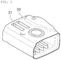
- FIG. 3 is a perspective view illustrating a center member 30 of a fuel tank 1 according to an example embodiment
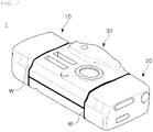
- FIG. 4 is a perspective view illustrating an example in which the fuel tank 1 according to an embodiment includes a center member 30
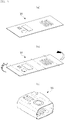
- FIG. 5 is a perspective view illustrating a process of manufacturing a center member 30 according to an embodiment
- FIG. 7 is a view illustrating a result of simulating the fuel tank 1 according to an embodiment.
- the fuel tank 1 is provided in the form of a tube, and may include a center member 30 having one end portion, to which the other side of the first recessed member 10 is coupled, and the other end portion, to which the other side of the second recessed member 20 is coupled, to form a hermetically closed space S.
- the center member 30 is further provided between the first recessed member 10 and the second recessed member 20 to expand the hermetically closed space S of the fuel tank 1.
- the center member 30 may be provided in the form of a tube having opposite open end portions. One end portion of the opposite open end portions may be coupled to the first recessed member 10 and the other end portion thereof may be coupled to the second recessed member 20, so that the three members may cooperate to form the hermetically closed space S.
- a stamping process may be performed to form a support groove portion 31 in a blank material.
- a bending process may be performed to form the blank material, in which the support groove portion 31 or the like is formed, in the form of a tube.
- a welding process may be performed to form the center member 30 such that the form of the tube may be maintained.
- the opposite end portions of the center member 30 may be coupled to the first recessed member 10 and the second recessed member 20 by welding.
- the center member 30 may be coupled to the first recessed member 10 and the second recessed member 20 by arc welding using a welding material.
- the arc welding may be performed by, for example, metal inert gas (MIG) welding, CO 2 welding, metal active gas (MAG) welding, or the like.
- MIG metal inert gas
- MAG metal active gas
- the arc welding may be a method in which an arc is generated between a welding material (a filler metal), a consumable wire supplied at a constant speed, and a base material and the welding material is melted by arc heat to form a bead.
- a protective gas for preventing permeation of foreign substances may be supplied together, so that air may be blocked to protect the arc and the molten portion.
- an inert gas such as argon (Ar), a carbon dioxide gas, or a mixed gas thereof may be used.
- the stress when welding is not performed on the end portion, the stress may be concentrated in a portion of the base material, in which the welding portion W is formed, to increase an issue such as fracturing.
- the welding portion W is formed by welding portions between the end portion of the center member 30 and the first recessed member 10 and the second recessed members 20, an issue such as stress concentration may be alleviated.
- a fuel tank 1 may perform butt welding on a flange portion extending outwardly of an upper member and a lower member.
- a portion, in which a welding portion is formed may be an intermediate point of a member rather than an end portion of the member. Accordingly, stress may be concentrated in an intermediate portion, in which the flange portions of the upper member and lower member overlap each other, to result in an issue such as fracture of a welding portion W.
- the welding portion W may be formed in an end portion of a center member 30, so that stress may be prevented from concentrating in the welding portion W.
- FIG. 7 illustrates a simulation result, based on a maximum displacement value required in the fuel tank 1 and a count of repetitions of applying a positive pressure and a negative pressure, confirming that the maximum displacement value and the count were satisfied.
- a positive pressure of 0.35 bar and a negative pressure of -0.16 bar were applied, and a first number of repetitions were set to 0 bar ⁇ - 0.35 bar ⁇ - 0 bar ⁇ - -0.16 bar ⁇ - 0 bar.
- a maximum displacement value, a reference value is 10 mm and a reference repetition count is a value greater than 12000.
- the maximum displacement value of the fuel tank 1 according to an embodiment was 7.1 mm satisfying a reference value, and the repetition count was 15445, satisfying a reference value.
- a portion, to which maximum stress is applied is a bonding portion of the first recessed member 10 or the second recessed member 20 and the center member 30. It may also be confirmed that, in this case, the maximum stress is about 523 MPa.
- a buffer unit 40 to be described later may be provided to relieve such a stress concentration. A detailed description thereof will be described later with reference to FIG. 6 .
- the fuel tank 1 according to the embodiment may satisfy noise conditions depending on sloshing.
- the fuel tank 1 is decelerated at an initial speed of 8 km/h and -0.2 g (where g is acceleration of gravity), and noise is measured to be determined from a position 30 cm away from a front when the fuel tank 1 is stopped.
- a reference noise level at the time of stopping the fuel tank 1 is 65 dB or less.
- a support groove portion 31 may be formed in the center member 30 of the fuel tank 1 according to an embodiment in a length direction.
- the support groove portion 31 may further increase the rigidity of the fuel tank 1.
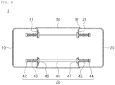
- FIG. 6 is a perspective view illustrating an example in which the fuel tank 1 includes the buffer unit 40.
- the buffer unit 40 may penetrate through the first flange portion 11 and the second flange portion 21, and may allow the first recessed member 10 and the second recessed member 2 to maintain elastic force.
- stress concentration in a bonding portion of the first recessed member 10 or the second recessed member 20 and the center member 30 may be relieved.
- a phenomenon in which the first recessed member 10 and the second recessed member 20, respectively coupled to opposite end portions of the center member 30, move away from each other due to an increase in pressure inside the fuel tank 1, may be alleviated to relieve stress concentration in a coupling portion of the center member 30 and the first recessed member 10 or the second recessed member 20.
- the buffer unit 40 may include a support bar 41 provided to penetrate through a through-hole "h" formed in each of the first flange portion 11 and the second flange portion 21, a first stepped bolt 42 coupled to one end portion of the support bar 41, a first spring 43 provided between the first stepped bolt 42 and the first flange portion 11, a second stepped bolt 44 coupled to the other end portion of the support bar 41, and a second spring 45 provided between the second stepped bolt 44 and the second flange portion 21.
- the support bar 41 may connects the first recessed member 10 and the second recessed member 20 to each other, and may be disposed to penetrate through the through-hole "h" of each of the first recessed member 10 and the second recessed member 20.
- the first spring 43 and the second spring 45 may be connected to the support bar 41, provided between the first recessed member 10 and the second recessed member 20, to elastically connect the first recessed member 10 and the second recessed member 20 to each other.
- the first spring 43 may be disposed between the first stepped bolt 42 and the first flange portion 11 to be configured such that the first flange portion 11 may have elastic force toward the second recessed member 20.
- the second spring 45 may be disposed between the second stepped bolt 44 and the second flange portion 21 to be configured such that the second flange portion 21 may have elastic force toward the first recessed member 10.
- first recessed member 10 and the second recessed member 20 may be prevented from being separated from each other when the pressure inside the fuel tank 1 is increased.
- tensile stress may be prevented from being concentrated in the welding portion W for coupling between the first recessed member 10 or the second recessed member 20 and the center member 30.
- the buffer unit 40 may further include a first stop tab 46 and a second stop tab 47 to prevent compressive stress from being concentrated between the center member 30 and the first recessed member 10 or the second recessed member 20.
- the buffer unit 40 of the fuel tank 1 may include the first stop tab 46, coupled to the support bar 41, provided to be adjacent to the first flange portion 11, and disposed in a more inner position of the center member 30 than the first flange portion 11, and the second stop tab 47 coupled to the support bar 41, provided to be adjacent to the second flange portion 21, and disposed in a more inner position of the center member 30 than the second flange portion 21.
- the first stop tab 46 and the second stop tab 47 may compensate for tensile stress caused by an increase in pressure inside the fuel tank 1 in a coupling portion between the center member 30 and the first recessed member 10 or the second recessed member 20.
- the first stop tab 46 may be disposed inwardly of the center member 30 from the first flange portion 11 in a direction toward a central portion of the center member 30.
- the second stop tab 47 may be disposed inwardly of the center member 30 from the second flange portion 21 in a direction toward the central portion of the center member 3 to be configured to compensate for tensile stress in a state in which the pressure inside the fuel tank 1 is increased.
- FIG. 8 is a diagram illustrating a vehicle including a fuel tank 1 according to an embodiment.
- the vehicle according to an embodiment may include the fuel tank 1, a driving engine configured to generate driving force with fuel stored in the fuel tank 1, and a body frame 3, in which the fuel tank 1 and the driving engine 2 are mounted, provided with a wheel member 4 connected to the driving engine 2 to receive the driving force.
- the vehicle according to the embodiment may include the above-described fuel tank 1 such that rigidity may be reinforced to prevent the fuel tank 1 from being damaged by evaporation of fuel inside the fuel tank 1 and, in another aspect, to reduce expansion force generated by an increase in the pressure resulting from the evaporation of the fuel inside the fuel tank 1.
- the driving engine 2 may be a driving engine 2 using some liquid fuel of a gasoline engine, a diesel engine, or the like, which may provide driving force to the wheel member 4, and the body frame 3 may include all frames constituting a vehicle including an underframe, a side frame, and the like.
Landscapes
- Engineering & Computer Science (AREA)
- Mechanical Engineering (AREA)
- Chemical & Material Sciences (AREA)
- Transportation (AREA)
- Combustion & Propulsion (AREA)
- General Engineering & Computer Science (AREA)
- Life Sciences & Earth Sciences (AREA)
- Sustainable Development (AREA)
- Sustainable Energy (AREA)
- Aviation & Aerospace Engineering (AREA)
- Acoustics & Sound (AREA)
- Physics & Mathematics (AREA)
- Cooling, Air Intake And Gas Exhaust, And Fuel Tank Arrangements In Propulsion Units (AREA)
Abstract
Description
- The present disclosure relates to a fuel tank and a vehicle including the same.
- With the expansion of production of eco-friendly vehicles for reducing vehicle exhaust gas, the development and distribution of plug-in hybrid vehicles is expanding.
- A plug-in hybrid vehicle may simultaneously use engine power of an internal combustion engine vehicle according to the related art and motor power of an electric vehicle to achieve both vehicle power and high-fuel efficiency.
- When a plug-in hybrid vehicle travels long distance in a pure electric mode, an internal combustion engine is not used, so that a use rate of a fuel tank may be decreased.
- In this case, pressure inside the fuel tank is increased by about 2 to 3 times due to evaporation of the fuel inside the fuel tank, as compared with that of the related art.
- An aspect of the present disclosure is to provide a fuel tank having reinforced rigidity to prevent damage to the fuel tank, resulting from an increase in pressure caused by evaporation of fuel inside the fuel tank, and a vehicle including the fuel tank.
- Another aspect of the present disclosure is to provide a fuel tank reducing expansion force, generated by an increase in pressure caused by evaporation of fuel inside the fuel tank, and a vehicle including the fuel tank.
- According to an aspect of the present disclosure, a fuel tank includes a first recessed member and a second recessed member disposed to oppose the other side of the first recessed member. The first recessed member is recessed on one side thereof to form a receiving space and is open on the other side thereof, and includes a first flange portion bent to cover a portion of the receiving space. The second recessed member is recessed on one side thereof to form a receiving space and is open on the other side thereof, and includes a second flange portion bent to cover a portion of the receiving space.
- The first flange portion and the second flange portion of the fuel tank according to an embodiment may overlap each other, and an overlapping portion of the first flange and the second flange may be welded to be fixed.
- Each of the first flange portion and the second flange portion of the fuel tank according to an embodiment may have a through-hole, formed therein, through which fuel passes.
- The fuel tank according to an embodiment may be provided in the form of a tube, and may include a center member having one end portion, to which the other side of the first recessed member is coupled, and the other end portion, to which the other side of the second recessed member is coupled, to form a hermetically closed space.
- The center member of the fuel tank according to an embodiment may have a support groove portion formed therein in a length direction.
- The center member of the fuel tank according to an embodiment may be coupled to the first recessed member in a circumferential direction of one end portion by arc welding and coupled to the second recessed member in a circumferential direction of the other end portion by arc welding.
- The fuel tank according to an embodiment may include a buffer unit penetrating through and connecting the first flange portion and the second flange portion. The buffer unit may maintain a gap between the first flange portion and the second flange portion, connected to each other via the center member, with elastic force.
- For example, the buffer unit of the fuel tank according to an embodiment may include a support bar penetrating through a through-hole formed in each of the first flange portion and the second flange portion, a first stepped bolt coupled to one end portion of the support bar, a first spring provided between the first stepped bolt and the first flange portion, a second stepped bolt coupled to the other end portion of the support bar, and a second spring provided between the second stepped bolt and the second flange portion.
- In addition, the buffer unit of the fuel tank according to an embodiment may include a first stop tab, coupled to the support bar, provided to be adjacent to the first flange portion, and disposed in a more inner position of the center member than the first flange portion, and a second stop tab coupled to the support bar, provided to be adjacent to the second flange portion, and disposed in a more inner position of the center member than the second flange portion.
- According to another aspect of the present disclosure, a vehicle includes the above-described fuel tank, a driving engine configured to generate driving force with fuel stored in the fuel tank, and a body frame, in which the fuel tank and the driving engine are mounted, provided with a wheel member connected to the driving engine to receive the driving force.
- As described above, according to example embodiments, a fuel tank and a vehicle including the fuel tank may reinforce rigidity to prevent damage to the fuel tank resulting from an increase in pressure caused by evaporation of fuel inside the fuel tank.
- In another aspect, a fuel tank and a vehicle including the fuel tank may reduce expansion force generated by an increase in pressure caused by evaporation of fuel inside the fuel tank.
-
-
FIG. 1 is an exploded perspective view illustrating a fuel tank according to an embodiment in the present disclosure. -
FIG. 2 is a perspective view illustrating a process of manufacturing a first recessed member of a fuel tank according to an embodiment. -
FIG. 3 is a perspective view illustrating a center member of a fuel tank according to an example embodiment. -
FIG. 4 is a perspective view illustrating an example including a center member of a fuel tank according to an embodiment. -
FIG. 5 is a perspective view illustrating a process of manufacturing a center member of a fuel tank according to an embodiment. -
FIG. 6 is a perspective view illustrating an example including a buffer unit of a fuel tank according to an embodiment. -
FIG. 7 is a view illustrating a result of simulating a fuel tank according to an embodiment. -
FIG. 8 illustrates a vehicle including a fuel tank according to an embodiment. - Hereinafter, exemplary embodiments of the present disclosure will be described with reference to the accompanying drawings. However, embodiments of the present disclosure may be modified into various other forms, and the scope of the present disclosure is not limited to the embodiments described below. In addition, embodiments of the present disclosure may be provided in order to more completely explain the present disclosure to those with average knowledge in the art. In the drawings, shapes and sizes of elements may be exaggerated for clarity.
- In addition, in the present specification, it should be understood that singular expressions include plural expressions unless clearly defined otherwise in the context, and reference numerals given in the same reference numerals or in a similar manner throughout the specification refer to the same elements or corresponding elements.
-
FIG. 1 is an exploded perspective view illustrating afuel tank 1 according to an embodiment, andFIG. 2 is a perspective view illustrating a process of manufacturing a first recessedmember 10 of thefuel tank 1 according to an embodiment. - The
fuel tank 1 according to an embodiment may include a firstrecessed member 10 and a secondrecessed member 20. - The first
recessed member 10 may be recessed on one side thereof to form a receiving space and may be open on the other side thereof. The firstrecessed member 10 may include afirst flange portion 11 bent to cover the receiving space. - The second
recessed member 20 may be disposed to oppose the other side of the first recessedmember 10. The secondrecessed member 20 may be recessed on one side thereof to form a receiving space and may be open on the other side thereof. The secondrecessed member 20 may include asecond flange portion 21 bent to cover the receiving space. - In the
fuel tank 1 according to the embodiment, the firstrecessed member 10 including thefirst flange portion 11 and the second recessedmember 20 including thesecond flange portion 21 may be coupled to each other, so that the receiving space of the first receivedmember 10 and the receiving space of the second receivedmember 20 may be combined to form a hermetically closed space S. - Accordingly, rigidity may be secured to prevent damage resulting from an increase in pressure caused by evaporation of fuel inside the
fuel tank 1. - As an example, one side of each of the first
recessed member 10 and the secondrecessed member 20 may be recessed to form a receiving space, and the other side thereof may have an open can shape. For example, one end portion of each of the first recessedmember 10 and the secondrecessed member 20 may be closed and the other end thereof may have an open can shape, and the firstrecessed member 10 and the secondrecessed member 20 may be disposed such that the hermetically closed space S is formed by coupling the other end portions having a can shape, open to each other. A flange shape may be added to the other end portion of the can shape to reinforce rigidity. - In particular, a portion remaining during forming of the first recessed
member 10 or the second recessedmember 20 may be formed as thefirst flange portion 11 or thesecond flange portion 21 to increase a use rate of a material and to secure target rigidity. - Hereinafter, a process of forming the first recessed
member 10 or the second recessedmember 20 will be described. As illustrated inFIG. 2A , a receiving space for receiving fuel may be formed in a blank material by a drawing process. In this case, in addition to a portion forming the receiving space, a portion remaining to fix the blank material may be formed. As illustrated inFIG. 2B , the portion remaining after forming the receiving space may be subjected to a trimming process to form thefirst flange portion 11 or thesecond flange portion 21. As illustrated inFIGS. 2C and 2D , a bending process may be performed such that the first flange portion or the second flange portion is bent to cover a portion of the receiving space. As illustrated inFIG. 2E , a welding process may be performed such that an overlapping portion of the bentfirst flange portion 11 or the bentsecond flange portion 21 is fixed by welding to increase rigidity. - As described above, the first recessed
member 10 and the second recessedmember 20 may be coupled to each other to form the hermetically closed space S to provide thefuel tank 1 in which fuel may be contained. - In this case, the first recessed
member 10 and the second recessedmember 20 may be directly coupled to each other to form the internal hermetically-closed space S, or acenter member 30 may be provided between the recessedmember 10 and the second recessedmember 20 to expand the internal hermetically-closed space S. An embodiment including thecenter member 30 will be described later with reference toFIGS. 3 to 7 . - The
first flange portion 11 and thesecond flange portion 21 of thefuel tank 1 according to an embodiment may be bent into the receiving space, and overlapping portions thereof may be welded to be fixed. - A process of welding the overlapping portions may be a spot welding process, or an arc welding process using a welding material.
- In addition, a through-hole "h" may be formed in each of the
first flange portion 11 and thesecond flange portion 21 of thefuel tank 1 according to an embodiment. - The through-hole "h" allows the fuel inside the
fuel tank 1 to be flowable. - In the through-hole (h), a
support bar 41 of abuffer unit 40 to be described later may be disposed to buffer an increase in pressure inside thefuel tank 1. A detailed description thereof will be described later with reference toFIG. 6 . -
FIG. 3 is a perspective view illustrating acenter member 30 of afuel tank 1 according to an example embodiment,FIG. 4 is a perspective view illustrating an example in which thefuel tank 1 according to an embodiment includes acenter member 30,FIG. 5 is a perspective view illustrating a process of manufacturing acenter member 30 according to an embodiment, andFIG. 7 is a view illustrating a result of simulating thefuel tank 1 according to an embodiment. - The
fuel tank 1 according to an embodiment is provided in the form of a tube, and may include acenter member 30 having one end portion, to which the other side of the first recessedmember 10 is coupled, and the other end portion, to which the other side of the second recessedmember 20 is coupled, to form a hermetically closed space S. - The
center member 30 is further provided between the first recessedmember 10 and the second recessedmember 20 to expand the hermetically closed space S of thefuel tank 1. - For example, the
center member 30 may be provided in the form of a tube having opposite open end portions. One end portion of the opposite open end portions may be coupled to the first recessedmember 10 and the other end portion thereof may be coupled to the second recessedmember 20, so that the three members may cooperate to form the hermetically closed space S. - Hereinafter a process of forming the
center member 30 will be described. As illustrated inFIG. 5A , a stamping process may be performed to form asupport groove portion 31 in a blank material. As illustrated inFIG. 5B , a bending process may be performed to form the blank material, in which thesupport groove portion 31 or the like is formed, in the form of a tube. As illustrated inFIG. 5C , a welding process may be performed to form thecenter member 30 such that the form of the tube may be maintained. - The opposite end portions of the
center member 30 may be coupled to the first recessedmember 10 and the second recessedmember 20 by welding. In this case, thecenter member 30 may be coupled to the first recessedmember 10 and the second recessedmember 20 by arc welding using a welding material. - The arc welding may be performed by, for example, metal inert gas (MIG) welding, CO2 welding, metal active gas (MAG) welding, or the like. The arc welding may be a method in which an arc is generated between a welding material (a filler metal), a consumable wire supplied at a constant speed, and a base material and the welding material is melted by arc heat to form a bead.
- In this case, a protective gas for preventing permeation of foreign substances may be supplied together, so that air may be blocked to protect the arc and the molten portion. As the protective gas, an inert gas such as argon (Ar), a carbon dioxide gas, or a mixed gas thereof may be used.
- Since the coupling of the
center member 30 and the first recessedmember 10 and the second recessedmember 20 is performed in an end portion of thecenter member 30, stress concentration may be prevented and tighter welding coupling may be achieved when a welding portion W is formed by arc welding. - For example, when welding is not performed on the end portion, the stress may be concentrated in a portion of the base material, in which the welding portion W is formed, to increase an issue such as fracturing. However, since the welding portion W is formed by welding portions between the end portion of the
center member 30 and the first recessedmember 10 and the second recessedmembers 20, an issue such as stress concentration may be alleviated. - A
fuel tank 1 according to the related art may perform butt welding on a flange portion extending outwardly of an upper member and a lower member. A portion, in which a welding portion is formed, may be an intermediate point of a member rather than an end portion of the member. Accordingly, stress may be concentrated in an intermediate portion, in which the flange portions of the upper member and lower member overlap each other, to result in an issue such as fracture of a welding portion W. However, according to an embodiment, the welding portion W may be formed in an end portion of acenter member 30, so that stress may be prevented from concentrating in the welding portion W. -
FIG. 7 illustrates a simulation result, based on a maximum displacement value required in thefuel tank 1 and a count of repetitions of applying a positive pressure and a negative pressure, confirming that the maximum displacement value and the count were satisfied. - As experimental conditions, a positive pressure of 0.35 bar and a negative pressure of -0.16 bar were applied, and a first number of repetitions were set to 0 bar →- 0.35 bar →- 0 bar →- -0.16 bar →- 0 bar. In addition, a maximum displacement value, a reference value, is 10 mm and a reference repetition count is a value greater than 12000.
- The maximum displacement value of the
fuel tank 1 according to an embodiment was 7.1 mm satisfying a reference value, and the repetition count was 15445, satisfying a reference value. - According to the simulation, it may be confirmed that a portion, to which maximum stress is applied, is a bonding portion of the first recessed
member 10 or the second recessedmember 20 and thecenter member 30. It may also be confirmed that, in this case, the maximum stress is about 523 MPa. - Accordingly, a
buffer unit 40 to be described later may be provided to relieve such a stress concentration. A detailed description thereof will be described later with reference toFIG. 6 . - The
fuel tank 1 according to the embodiment may satisfy noise conditions depending on sloshing. - In the noise conditions, the
fuel tank 1 is decelerated at an initial speed of 8 km/h and -0.2 g (where g is acceleration of gravity), and noise is measured to be determined from aposition 30 cm away from a front when thefuel tank 1 is stopped. A reference noise level at the time of stopping thefuel tank 1 is 65 dB or less. - It was confirmed that a value of 57.8 dB, smaller than an existing noise level, was derived in the
fuel tank 1 according to an embodiment. - A
support groove portion 31 may be formed in thecenter member 30 of thefuel tank 1 according to an embodiment in a length direction. Thesupport groove portion 31 may further increase the rigidity of thefuel tank 1. -
FIG. 6 is a perspective view illustrating an example in which thefuel tank 1 includes thebuffer unit 40. Thebuffer unit 40 may penetrate through thefirst flange portion 11 and thesecond flange portion 21, and may allow the first recessedmember 10 and the second recessedmember 2 to maintain elastic force. - Accordingly, stress concentration in a bonding portion of the first recessed
member 10 or the second recessedmember 20 and thecenter member 30 may be relieved. - In other words, a phenomenon, in which the first recessed
member 10 and the second recessedmember 20, respectively coupled to opposite end portions of thecenter member 30, move away from each other due to an increase in pressure inside thefuel tank 1, may be alleviated to relieve stress concentration in a coupling portion of thecenter member 30 and the first recessedmember 10 or the second recessedmember 20. - The
buffer unit 40 according to the embodiment may include asupport bar 41 provided to penetrate through a through-hole "h" formed in each of thefirst flange portion 11 and thesecond flange portion 21, a first steppedbolt 42 coupled to one end portion of thesupport bar 41, afirst spring 43 provided between the first steppedbolt 42 and thefirst flange portion 11, a second steppedbolt 44 coupled to the other end portion of thesupport bar 41, and asecond spring 45 provided between the second steppedbolt 44 and thesecond flange portion 21. - The
support bar 41 may connects the first recessedmember 10 and the second recessedmember 20 to each other, and may be disposed to penetrate through the through-hole "h" of each of the first recessedmember 10 and the second recessedmember 20. - The
first spring 43 and thesecond spring 45 may be connected to thesupport bar 41, provided between the first recessedmember 10 and the second recessedmember 20, to elastically connect the first recessedmember 10 and the second recessedmember 20 to each other. - For example, the
first spring 43 may be disposed between the first steppedbolt 42 and thefirst flange portion 11 to be configured such that thefirst flange portion 11 may have elastic force toward the second recessedmember 20. - In addition, the
second spring 45 may be disposed between the second steppedbolt 44 and thesecond flange portion 21 to be configured such that thesecond flange portion 21 may have elastic force toward the first recessedmember 10. - Accordingly, the first recessed
member 10 and the second recessedmember 20 may be prevented from being separated from each other when the pressure inside thefuel tank 1 is increased. In addition, tensile stress may be prevented from being concentrated in the welding portion W for coupling between the first recessedmember 10 or the second recessedmember 20 and thecenter member 30. - The
buffer unit 40 may further include afirst stop tab 46 and asecond stop tab 47 to prevent compressive stress from being concentrated between thecenter member 30 and the first recessedmember 10 or the second recessedmember 20. - For example, the
buffer unit 40 of thefuel tank 1 according to an embodiment may include thefirst stop tab 46, coupled to thesupport bar 41, provided to be adjacent to thefirst flange portion 11, and disposed in a more inner position of thecenter member 30 than thefirst flange portion 11, and thesecond stop tab 47 coupled to thesupport bar 41, provided to be adjacent to thesecond flange portion 21, and disposed in a more inner position of thecenter member 30 than thesecond flange portion 21. - The
first stop tab 46 and thesecond stop tab 47 may compensate for tensile stress caused by an increase in pressure inside thefuel tank 1 in a coupling portion between thecenter member 30 and the first recessedmember 10 or the second recessedmember 20. - For example, when additional pressure change does not occur in the hermetically closed space S of the
fuel tank 1, thefirst stop tab 46 may be disposed inwardly of thecenter member 30 from thefirst flange portion 11 in a direction toward a central portion of thecenter member 30. In addition, thesecond stop tab 47 may be disposed inwardly of thecenter member 30 from thesecond flange portion 21 in a direction toward the central portion of thecenter member 3 to be configured to compensate for tensile stress in a state in which the pressure inside thefuel tank 1 is increased. -
FIG. 8 is a diagram illustrating a vehicle including afuel tank 1 according to an embodiment. The vehicle according to an embodiment may include thefuel tank 1, a driving engine configured to generate driving force with fuel stored in thefuel tank 1, and abody frame 3, in which thefuel tank 1 and the drivingengine 2 are mounted, provided with awheel member 4 connected to the drivingengine 2 to receive the driving force. - As described above, the vehicle according to the embodiment may include the above-described
fuel tank 1 such that rigidity may be reinforced to prevent thefuel tank 1 from being damaged by evaporation of fuel inside thefuel tank 1 and, in another aspect, to reduce expansion force generated by an increase in the pressure resulting from the evaporation of the fuel inside thefuel tank 1. - The driving
engine 2 may be a drivingengine 2 using some liquid fuel of a gasoline engine, a diesel engine, or the like, which may provide driving force to thewheel member 4, and thebody frame 3 may include all frames constituting a vehicle including an underframe, a side frame, and the like. - While example embodiments have been shown and described above, it will be apparent to those skilled in the art that modifications and variations could be made without departing from the scope of the present disclosure as defined by the appended claims.
Claims (10)
- A fuel tank comprising:a first recessed member; anda second recessed member disposed to oppose the other side of the first recessed member,wherein the first recessed member is recessed on one side thereof to form a receiving space,the first recessed member is open on the other side thereof and includes a first flange portion bent to cover a portion of the receiving space,the second recessed member is recessed on one side thereof to form a receiving space, andthe second recessed member is open on the other side thereof and includes a second flange portion bent to cover a portion of the receiving space.
- The fuel tank of claim 1, wherein the first flange portion and the second flange portion overlap each other, and an overlapping portion of the first flange and the second flange is welded to be fixed.
- The fuel tank of claim 1, wherein each of the first flange portion and the second flange portion has a through-hole, formed therein, through which fuel passes.
- The fuel tank of claim 1, comprising:
a center member having one end portion, to which the other side of the first recessed member is coupled, and the other end portion, to which the other side of the second recessed member is coupled, to form a hermetically closed space. - The fuel tank of claim 4, wherein the center member has a support groove portion formed therein in a length direction.
- The fuel tank of claim 4, wherein the center member is coupled to the first recessed member and the second recessed member by arc welding.
- The fuel tank of claim 4, comprising:
a buffer unit penetrating through the first flange portion and the second flange portion and maintaining a gap between the first recessed member and the second recessed member with elastic force. - The fuel tank of claim 7, wherein the buffer unit comprises:a support bar penetrating through a through-hole formed in each of the first flange portion and the second flange portion;a first stepped bolt coupled to one end portion of the support bar;a first spring provided between the first stepped bolt and the first flange portion;a second stepped bolt coupled to the other end portion of the support bar; anda second spring provided between the second stepped bolt and the second flange portion.
- The fuel tank of claim 8, wherein the buffer unit comprises:a first stop tab coupled to the support bar, provided to be adjacent to the first flange portion, and disposed in a more inner position of the center member than the first flange portion; anda second stop tab coupled to the support bar, provided to be adjacent to the second flange portion, and disposed in a more inner position of the center member than the second flange portion.
- A vehicle comprising:a fuel tank of any one of claims 1 to 9;a driving engine configured to generate driving force with fuel stored in the fuel tank; anda body frame, in which the fuel tank and the driving engine are mounted, provided with a wheel member connected to the driving engine to receive the driving force.
Applications Claiming Priority (2)
| Application Number | Priority Date | Filing Date | Title |
|---|---|---|---|
| KR1020190145300A KR102246859B1 (en) | 2019-11-13 | 2019-11-13 | Fuel tank and vehicle having thereof |
| PCT/KR2020/015409 WO2021096161A1 (en) | 2019-11-13 | 2020-11-05 | Fuel tank and vehicle comprising same |
Publications (4)
| Publication Number | Publication Date |
|---|---|
| EP4059756A1 true EP4059756A1 (en) | 2022-09-21 |
| EP4059756A4 EP4059756A4 (en) | 2023-01-11 |
| EP4059756B1 EP4059756B1 (en) | 2026-03-04 |
| EP4059756C0 EP4059756C0 (en) | 2026-03-04 |
Family
ID=75740923
Family Applications (1)
| Application Number | Title | Priority Date | Filing Date |
|---|---|---|---|
| EP20887905.6A Active EP4059756B1 (en) | 2019-11-13 | 2020-11-05 | Fuel tank and vehicle comprising same |
Country Status (4)
| Country | Link |
|---|---|
| EP (1) | EP4059756B1 (en) |
| KR (1) | KR102246859B1 (en) |
| CN (1) | CN114650925B (en) |
| WO (1) | WO2021096161A1 (en) |
Family Cites Families (14)
| Publication number | Priority date | Publication date | Assignee | Title |
|---|---|---|---|---|
| KR200162033Y1 (en) * | 1996-12-07 | 2000-01-15 | 정몽규 | Fuel tank of automobile |
| KR200197195Y1 (en) * | 1996-12-20 | 2000-10-02 | 정몽규 | Shock Absorber of Fuel Tank |
| JP3415113B2 (en) * | 2000-10-23 | 2003-06-09 | 日野自動車株式会社 | Baffle plate for vehicle fuel tank |
| KR100461442B1 (en) * | 2000-12-04 | 2004-12-14 | 현대자동차주식회사 | Baffle plate of fuel tank |
| JP2002362174A (en) * | 2001-04-03 | 2002-12-18 | Komatsu Ltd | Wheeled traveling work vehicle |
| KR100501220B1 (en) * | 2002-07-09 | 2005-07-18 | 우신산업(주) | The aluminum fuel tank for commercial vehicles |
| KR100494420B1 (en) * | 2003-08-08 | 2005-06-13 | 현대자동차주식회사 | Baffle in fuel tank |
| KR100658766B1 (en) * | 2006-07-03 | 2006-12-20 | 송왕호 | Cylindrical stainless steel water tank |
| KR100915132B1 (en) * | 2007-11-16 | 2009-09-07 | 한만성 | High Pressure Gas Container Manufacturing Method |
| KR100892820B1 (en) * | 2007-12-14 | 2009-04-10 | 현대자동차주식회사 | Baffle Plate of Fuel Tank |
| US20100102068A1 (en) * | 2008-10-24 | 2010-04-29 | Martinrea Industries, Inc. | Fuel tank and method for making same |
| DE102009036911B4 (en) * | 2009-08-11 | 2016-03-03 | Magna Steyr Fuel Systems Gmbh | Fuel tank for motor vehicles with tie rods |
| JP2017014926A (en) * | 2015-06-29 | 2017-01-19 | 本田技研工業株式会社 | Seal structure of fuel tank |
| JP2018111370A (en) * | 2017-01-10 | 2018-07-19 | トヨタ自動車株式会社 | Vehicle fuel tank |
-
2019
- 2019-11-13 KR KR1020190145300A patent/KR102246859B1/en active Active
-
2020
- 2020-11-05 WO PCT/KR2020/015409 patent/WO2021096161A1/en not_active Ceased
- 2020-11-05 EP EP20887905.6A patent/EP4059756B1/en active Active
- 2020-11-05 CN CN202080078267.6A patent/CN114650925B/en active Active
Also Published As
| Publication number | Publication date |
|---|---|
| CN114650925A (en) | 2022-06-21 |
| WO2021096161A1 (en) | 2021-05-20 |
| EP4059756B1 (en) | 2026-03-04 |
| CN114650925B (en) | 2025-03-14 |
| EP4059756A4 (en) | 2023-01-11 |
| KR102246859B1 (en) | 2021-04-30 |
| EP4059756C0 (en) | 2026-03-04 |
Similar Documents
| Publication | Publication Date | Title |
|---|---|---|
| KR102383255B1 (en) | Center floor panel for vehicle | |
| US9796424B2 (en) | Vehicle body frame and vehicle underfloor structure | |
| US9932072B2 (en) | Vehicle structure | |
| US11021193B2 (en) | Side rail and manufacturing method for side rail | |
| JP2004161092A (en) | Body layout structure of fuel cell system | |
| CN113753137A (en) | Vehicle rear structure | |
| KR20150013864A (en) | Bogie frame for railway vehicle | |
| US10926800B2 (en) | Suspension tower | |
| CN105728970B (en) | The manufacturing method of welding structural body | |
| US20140333095A1 (en) | Method for producing a body part of a vehicle and body part of a vehicle | |
| US12434649B2 (en) | Front vehicle-body structure | |
| US20220219528A1 (en) | Fuel cell vehicle | |
| JP2020015356A (en) | Vehicle lower part structure | |
| JP2018165138A (en) | Automobile vehicle | |
| US11247728B2 (en) | Vehicle body structure | |
| EP4059756B1 (en) | Fuel tank and vehicle comprising same | |
| KR20120045894A (en) | Sub-frame of vehicle | |
| US20180043763A1 (en) | Battery mounting frame | |
| JP4505716B2 (en) | Electric equipment fixing structure of vehicle | |
| JP6430094B2 (en) | Manufacturing method of rear axle | |
| US20240351420A1 (en) | Motor vehicle with rear impact force recovery by a traction battery tray | |
| US10336374B2 (en) | Vehicle rear portion structure | |
| US20200101988A1 (en) | Underfloor double skin structure, vehicle underfloor structure, and vehicle | |
| US11063272B2 (en) | Support frame for fuel cell and vehicle | |
| CN202175351U (en) | Rear corner column of container and container with same |
Legal Events
| Date | Code | Title | Description |
|---|---|---|---|
| STAA | Information on the status of an ep patent application or granted ep patent |
Free format text: STATUS: THE INTERNATIONAL PUBLICATION HAS BEEN MADE |
|
| PUAI | Public reference made under article 153(3) epc to a published international application that has entered the european phase |
Free format text: ORIGINAL CODE: 0009012 |
|
| STAA | Information on the status of an ep patent application or granted ep patent |
Free format text: STATUS: REQUEST FOR EXAMINATION WAS MADE |
|
| 17P | Request for examination filed |
Effective date: 20220601 |
|
| AK | Designated contracting states |
Kind code of ref document: A1 Designated state(s): AL AT BE BG CH CY CZ DE DK EE ES FI FR GB GR HR HU IE IS IT LI LT LU LV MC MK MT NL NO PL PT RO RS SE SI SK SM TR |
|
| A4 | Supplementary search report drawn up and despatched |
Effective date: 20221209 |
|
| RIC1 | Information provided on ipc code assigned before grant |
Ipc: F16F 15/04 20060101ALI20221205BHEP Ipc: B60K 5/12 20060101ALI20221205BHEP Ipc: B60K 15/03 20060101AFI20221205BHEP |
|
| DAV | Request for validation of the european patent (deleted) | ||
| DAX | Request for extension of the european patent (deleted) | ||
| GRAP | Despatch of communication of intention to grant a patent |
Free format text: ORIGINAL CODE: EPIDOSNIGR1 |
|
| STAA | Information on the status of an ep patent application or granted ep patent |
Free format text: STATUS: GRANT OF PATENT IS INTENDED |
|
| INTG | Intention to grant announced |
Effective date: 20251001 |
|
| GRAS | Grant fee paid |
Free format text: ORIGINAL CODE: EPIDOSNIGR3 |
|
| GRAA | (expected) grant |
Free format text: ORIGINAL CODE: 0009210 |
|
| STAA | Information on the status of an ep patent application or granted ep patent |
Free format text: STATUS: THE PATENT HAS BEEN GRANTED |
|
| AK | Designated contracting states |
Kind code of ref document: B1 Designated state(s): AL AT BE BG CH CY CZ DE DK EE ES FI FR GB GR HR HU IE IS IT LI LT LU LV MC MK MT NL NO PL PT RO RS SE SI SK SM TR |
|
| REG | Reference to a national code |
Ref country code: CH Ref legal event code: F10 Free format text: ST27 STATUS EVENT CODE: U-0-0-F10-F00 (AS PROVIDED BY THE NATIONAL OFFICE) Effective date: 20260304 Ref country code: GB Ref legal event code: FG4D |
|
| REG | Reference to a national code |
Ref country code: IE Ref legal event code: FG4D |
|
| REG | Reference to a national code |
Ref country code: DE Ref legal event code: R096 Ref document number: 602020068181 Country of ref document: DE |
|
| U01 | Request for unitary effect filed |
Effective date: 20260317 |
|
| U07 | Unitary effect registered |
Designated state(s): AT BE BG DE DK EE FI FR IT LT LU LV MT NL PT RO SE SI Effective date: 20260320 |
|
| PG25 | Lapsed in a contracting state [announced via postgrant information from national office to epo] |
Ref country code: RS Free format text: LAPSE BECAUSE OF FAILURE TO SUBMIT A TRANSLATION OF THE DESCRIPTION OR TO PAY THE FEE WITHIN THE PRESCRIBED TIME-LIMIT Effective date: 20260604 |
|
| PG25 | Lapsed in a contracting state [announced via postgrant information from national office to epo] |
Ref country code: ES Free format text: LAPSE BECAUSE OF FAILURE TO SUBMIT A TRANSLATION OF THE DESCRIPTION OR TO PAY THE FEE WITHIN THE PRESCRIBED TIME-LIMIT Effective date: 20260304 |
|
| PG25 | Lapsed in a contracting state [announced via postgrant information from national office to epo] |
Ref country code: PL Free format text: LAPSE BECAUSE OF FAILURE TO SUBMIT A TRANSLATION OF THE DESCRIPTION OR TO PAY THE FEE WITHIN THE PRESCRIBED TIME-LIMIT Effective date: 20260304 |
|
| PG25 | Lapsed in a contracting state [announced via postgrant information from national office to epo] |
Ref country code: GR Free format text: LAPSE BECAUSE OF FAILURE TO SUBMIT A TRANSLATION OF THE DESCRIPTION OR TO PAY THE FEE WITHIN THE PRESCRIBED TIME-LIMIT Effective date: 20260605 |
|
| PG25 | Lapsed in a contracting state [announced via postgrant information from national office to epo] |
Ref country code: NO Free format text: LAPSE BECAUSE OF FAILURE TO SUBMIT A TRANSLATION OF THE DESCRIPTION OR TO PAY THE FEE WITHIN THE PRESCRIBED TIME-LIMIT Effective date: 20260604 |
|
| PG25 | Lapsed in a contracting state [announced via postgrant information from national office to epo] |
Ref country code: HR Free format text: LAPSE BECAUSE OF FAILURE TO SUBMIT A TRANSLATION OF THE DESCRIPTION OR TO PAY THE FEE WITHIN THE PRESCRIBED TIME-LIMIT Effective date: 20260304 |