EP4059749A1 - A motor vehicle - Google Patents
A motor vehicle Download PDFInfo
- Publication number
- EP4059749A1 EP4059749A1 EP22162821.7A EP22162821A EP4059749A1 EP 4059749 A1 EP4059749 A1 EP 4059749A1 EP 22162821 A EP22162821 A EP 22162821A EP 4059749 A1 EP4059749 A1 EP 4059749A1
- Authority
- EP
- European Patent Office
- Prior art keywords
- pillar
- driver side
- driver
- windscreen
- straight
- Prior art date
- Legal status (The legal status is an assumption and is not a legal conclusion. Google has not performed a legal analysis and makes no representation as to the accuracy of the status listed.)
- Granted
Links
Images



Classifications
-
- B—PERFORMING OPERATIONS; TRANSPORTING
- B60—VEHICLES IN GENERAL
- B60J—WINDOWS, WINDSCREENS, NON-FIXED ROOFS, DOORS, OR SIMILAR DEVICES FOR VEHICLES; REMOVABLE EXTERNAL PROTECTIVE COVERINGS SPECIALLY ADAPTED FOR VEHICLES
- B60J1/00—Windows; Windscreens; Accessories therefor
- B60J1/02—Windows; Windscreens; Accessories therefor arranged at the vehicle front, e.g. structure of the glazing, mounting of the glazing
-
- B—PERFORMING OPERATIONS; TRANSPORTING
- B60—VEHICLES IN GENERAL
- B60J—WINDOWS, WINDSCREENS, NON-FIXED ROOFS, DOORS, OR SIMILAR DEVICES FOR VEHICLES; REMOVABLE EXTERNAL PROTECTIVE COVERINGS SPECIALLY ADAPTED FOR VEHICLES
- B60J1/00—Windows; Windscreens; Accessories therefor
- B60J1/004—Mounting of windows
-
- B—PERFORMING OPERATIONS; TRANSPORTING
- B60—VEHICLES IN GENERAL
- B60J—WINDOWS, WINDSCREENS, NON-FIXED ROOFS, DOORS, OR SIMILAR DEVICES FOR VEHICLES; REMOVABLE EXTERNAL PROTECTIVE COVERINGS SPECIALLY ADAPTED FOR VEHICLES
- B60J1/00—Windows; Windscreens; Accessories therefor
- B60J1/008—Windows; Windscreens; Accessories therefor of special shape, e.g. beveled edges, holes for attachment, bent windows, peculiar curvatures such as when being integrally formed with roof, door, etc.
-
- B—PERFORMING OPERATIONS; TRANSPORTING
- B60—VEHICLES IN GENERAL
- B60R—VEHICLES, VEHICLE FITTINGS, OR VEHICLE PARTS, NOT OTHERWISE PROVIDED FOR
- B60R13/00—Elements for body-finishing, identifying, or decorating; Arrangements or adaptations for advertising purposes
- B60R13/04—External Ornamental or guard strips; Ornamental inscriptive devices thereon
Definitions
- the invention relates to a motor vehicle, in particular a heavy goods vehicle, comprising a driver cabin having a driver side and a co-driver side, the driver cabin comprising:
- Such a motor vehicle is for example known from EP1152940B1 .
- the A-pillar contains a third order mathematical ellipse when viewed from the top of the motor vehicle which third order ellipse at the A-pillar may be blended with the front windscreen for letting the airflow on the front windscreen to change flow direction from an outward flow direction to a flow direction parallel to the side door in order to improve aerodynamic and fuel consumption efficiency of the motor vehicle.
- dimensions of the components of the driver cabin such as the front windscreen and the A-pillars will vary due to dimensional tolerances and thus that the aperture between the A-pillars will also vary due to e.g. manufacturing tolerances.
- a motor vehicle in particular a heavy goods vehicle, comprising a driver cabin having a driver side and a co-driver side, the driver cabin comprising:
- a motor vehicle according to the invention prior to mounting the outer width of the front windscreen at a specific height is up to 10 mm smaller than a distance between most forward inner edge of the driver side A-pillar and the most forward inner edge of the co-driver side A-pillar at the same height.
- the length of the straight windscreen driver side portion and the length of the straight windscreen co-driver side portion as seen in a usual driving direction of the motor vehicle is larger than 100 mm.
- aerodynamic drag is reduced since a flow direction of the airflow parallel to the side door will be maintained.
- each A-pillar trim comprises an A-pillar carrier attached to the respective A-pillar and a separate A-pillar cover attached to the A-pillar carrier.
- the A-pillar carrier then comprises at least four slot holes oriented in a usual driving direction of the motor vehicle and at least one stop plate hingeably connected to the A-pillar carrier, a trailing side of the stop plate being in line with the leading edge of the respective door in a closed position.
- the A-pillar carrier has two stop plates hingeably connected to the A-pillar carrier, the trailing side of each of the stop plates being in line with the leading edge of the respective door in the closed position, so that a proper alignment of the A-pillar carrier to the respective side door can be attained.
- the vertical orientation of the A-pillar carrier with regard to the respective A-pillar is determined by the second slot hole seen from the top.
- the A-pillar cover and the A-pillar carrier are snap fitted together by means of first snap fit means on the A-pillar cover and second snap fit means on the A-pillar carrier cooperating with the first snap fit means.
- first snap fit means on the A-pillar cover and second snap fit means on the A-pillar carrier cooperating with the first snap fit means.
- the A-pillar cover comprises of leading sealing and a trailing sealing, the trailing sealing engaging an inner side of the leading edge of the respective door, the leading sealing engaging an outer side of the rear edge of the respective straight windscreen side portion.
- gaps between front windscreen and side doors can be covered and flushness between the front windscreen side portions and the side doors can be obtained in a relatively easy manner.
- the A-pillar cover comprises an A-pillar main body and the leading sealing and the trailing sealing, wherein the A-pillar main body and the sealings are formed by a 2K-process.
- the A-pillar carrier comprises ridges extending in vertical direction, the ridges being provided on a side of the A-pillar carrier directed towards the respective door, the ridges engaging the trailing sealing of the A-pillar cover.
- a motor vehicle according to the invention is schematically shown in perspective.
- the motor vehicle is a heavy goods vehicle 1 comprising a driver cabin 2 having a driver side 3 and a co-driver side 4 positioned at the opposite side of the driver side 3.
- the driver cabin 2 comprises a driver side A-pillar 5, a co-driver side A-pillar 6 (see e.g. Fig. 2 ), a driver side B-pillar 7 and a co-driver side B-pillar (not visible in Figure 1 ).
- a front windscreen 8 extends at an outside of the driver side A-pillar 5 and at an outside of the co-driver side A-pillar 6.
- the front windscreen 8 has a central windscreen section 8A, curved corners 8B and a straight windscreen driver side portion 8C and a straight windscreen co-driver side portion 8D as indicated in Figure 2 .
- the driver cabin 2 has a driver side door 9 hingeably mounted to the driver side of the driver cabin 2.
- the driver side door 9 extends between the driver side A-pillar 5 and the driver side B-pillar 7.
- the drive side door 9 has a leading edge 10 facing the driver side A-pillar 5 and a trailing edge 11 facing the driver side B-pillar 7.
- the co-driver side door is hingeably mounted to the co-driver side4 of the driver cabin 2 and extends between the co-driver side A-pillar 6 and the co-driver side B-pillar.
- the co-drive side door has a leading edge 14 (see Fig. 2 ) facing the co-driver side A-pillar 6 and a trailing edge facing the co-driver side B-pillar.
- the central windscreen section 8A covers an aperture between the driver side A-pillar 5 and the co-driver side A-pillar 6.
- the straight windscreen driver side portion 8C has a rear edge 12 facing and spaced from the leading edge 10 of the driver side door 9 (see Fig. 5 ).
- the straight windscreen co-driver side portion 8D has a rear edge 14 (see Fig. 2 ) facing the leading edge of the co-driver side door.
- a driver side gap 15 (see Fig. 5 and 12 ) is present between the rear edge 12 of the straight windscreen driver side portion 8C and the leading edge 10 of the driver side door 9.
- the front windscreen 8 is glued in an overstressed mounted state to the driver side A-pillar 5 and the co-driver side A-pillar 6 as will be explained with reference to Figures 2 to 4 .
- a front windscreen 8 is used of which an outer width w at a specific height prior to mounting is smaller than a distance d between a most forward inner edge 5A of the driver side A-pillar 5 and a most forward inner edge 6A of the co-driver side A-pillar 6 at the same specific height.
- the outer width w of the front windscreen 8 at a specific height is up to 10 mm smaller than a distance d between most forward inner edge 5A of the driver side A-pillar 5 and the most forward inner edge 6A of the co-driver side A-pillar 6 at the same height.
- the front windscreen 8 is mounted onto the A-pillars 5, 6 by bending the front windscreen 8 open as indicated by the arrow in Figure 2 . In this manner the width of the front windscreen 8 is enlarged such that it becomes larger than the distance d. Then the front windscreen 8 is placed over the driver side A-pillar 5 and co-driver side A-pillar 6, on which previously glue has been applied, and the front windscreen is released such that it is in contact with the A-pillars, as indicated in Figure 4 for the driver side A-pillar 5. In this manner the front windscreen 8 is mounted in an overstressed state to the A-pillars 5, 6.
- the described mounting of the front windscreen 8 can for example be performed by mounting robots.
- mounting the front windscreen 8 is performed such that the rear edge 12 of the straight windscreen driver side portion 8C is positioned on the outside of the driver side A-pillar 5 between the most forward inner edge 5A of the driver side A-pillar 5 and an outer edge 5B of the driver side A-pillar 5.
- the length of the straight windscreen driver side portion 8C and the length of the straight windscreen co-driver side portion 8D as seen in a usual driving direction of the heavy goods vehicle 1 is larger than 100 mm as a result of which aerodynamic drag is reduced.
- the driver side door 9 In assembling the driver side door 9 to the driver cabin 2 the driver side door 9 is positioned relative to the driver side B-pillar 7 in order to obtain a defined gap and flushness between the driver side door and the B-pillar 7 in order to obtain good aerodynamic properties at the interface between the driver side door 9 and the driver side B-pillar 7. Due to e.g. manufacturing tolerances positioning the driver side door 9 with regard to the driver side B-pillar 7 can result in gaps 15 at the driver side A-pillar 5 which varies from one heavy goods vehicle 1 to the other.
- gaps 15 of varying dimensions can be closed and flushness between the straight windscreen driver side portion 8C and the driver side door 9 can be realized by providing a driver side A-pillar trim 16 arranged for covering the driver side gap 15 and for providing flushness between the straight windscreen driver side portion 8C and the driver side door 9.
- a similar co-driver side A-pillar trim is arranged for covering the co-driver side gap and for providing flushness between the straight windscreen co-driver side portion and the co-driver side door.
- the construction of the A-pillar trim will be discussed below with regard to the driver side A-pillar trim 16, however it will be understood that the description also holds for the co-driver side A-pillar trim.
- the A-pillar trim 16 comprises an A-pillar carrier 18 (see e.g. Figure 7 ) to be attached to the A-pillar 5 and a separate A-pillar cover 17 (see e.g. Figure 6 ) to be attached to the A-pillar carrier 18.
- the A-pillar carrier 18 comprises at least four slot holes 19 oriented in a usual driving direction of the heavy goods vehicle 1.
- the A-pillar carrier 18 is provided with at least one stop plate 20, preferably two stop plates 20 are provided, which stop plates 20 are hingeably connected to the A-pillar carrier 18. This can for example be realized by injection moulding the A-pillar carrier 18, in which moulding process the stop plates are arranged to be hingeable along line-hinges.
- the A-pillar carrier 18 is positioned on the driver side A-pillar 5 and by the virtue of the slot holes 19 is slid towards the driver side door 9 until a trailing side 20A (see Figure 10 ) of the stop plate 20 is in contact with the leading edge 10 of the driver side door 9 in closed position.
- the vertical orientation of the A-pillar carrier 18 with regard to the driver side A-pillar 5 is determined by the second slot hole 19 seen from the top, although in other embodiments the top most slot hole 19 can be used.
- the A-pillar carrier 18 is correctly positioned with regard to the driver side door 9, and is attached to the driver side A-pillar 18 by means of e.g. screws or bolts passing through the slotted holes 19.
- the stop plates 20 are then pushed back into openings 21 in the A-pillar carrier 18 so that they are not protruding.
- the A-pillar cover 17 and the A-pillar carrier 18 are snap fitted together by means of first snap fit means 22 on the A-pillar cover 17 and second snap fit means 23 on the A-pillar carrier 18, which snap fit means 22, 23 cooperate with each other.
- Exemplary embodiments of such snap fit means 22A, 22B and 23A, 23B are indicated in Figures 13 and 14 , and different kinds of snap fit means 22A, 22B; 23A, 23B can be incorporated into an A-pillar trim 18 at different heights as indicated in Figure 11 .
- the A-pillar cover 17 comprises of leading sealing 17A and a trailing sealing 17B as shown in Figures 12 to 14 .
- the trailing sealing 17B engages an inner side of the leading edge 10 of the driver side door 9, while the leading sealing 17A engages an outer side of the rear edge 12 of the driver side straight windscreen side portion 8C.
- a top of the leading sealing 17A and a top of the trailing sealing 17B are connected to each other by a top sealing 17C, which top sealing 17C in assembled states of the driver cabin 2 engages a roof of the driver cabin 2.
- the A-pillar cover 17 comprises an A-pillar main body 17D and the sealings 17A-17C, wherein the A-pillar main body 17D and the sealings 17A-C are formed by a 2K-process.
- the A-pillar cover 17 can be prone to rotations along the vertical axis as result of opening and closing movements of the driver side door 9, which could result in wear and an unwanted open gap condition between the leading sealing 17A and the front windscreen.
- the A-pillar carrier 18 By providing the A-pillar carrier 18 with ridges 24 which extend in vertical direction, which ridges 24 are provided on a side of the A-pillar carrier 18 directed towards the driver side door 9 as shown in Figures 7, 9 and 11 , the ridges 24 engage the trailing sealing 17B of the A-pillar cover 17. In this manner rotation of the A-pillar cover 17 as a result of opening and closing movements of the driver side door 9 can be avoided.
Landscapes
- Engineering & Computer Science (AREA)
- Mechanical Engineering (AREA)
- Body Structure For Vehicles (AREA)
Abstract
Description
- The invention relates to a motor vehicle, in particular a heavy goods vehicle, comprising a driver cabin having a driver side and a co-driver side, the driver cabin comprising:
- a driver side A-pillar, a co-driver side A-pillar, a driver side B-pillar and a co-driver side B-pillar;
- a front windscreen having a central windscreen section, curved corners and a straight windscreen driver side portion and a straight windscreen co-driver side portion;
- a driver side door hingeably mounted to the driver side of the driver cabin and extending between the driver side A-pillar and the driver side B-pillar, the drive side door having a leading edge facing the driver side A-pillar and a trailing edge facing the driver side B-pillar, and a co-driver side door hingeably mounted to the co-driver side of the driver cabin and extending between the co-driver side A-pillar and the co-driver side B-pillar, the co-drive side door having a leading edge facing the co-driver side A-pillar and a trailing edge facing the co-driver side B-pillar;
- the front windscreen extending at an outside of the driver side A-pillar and at an outside of the co-driver side A-pillar, the central windscreen section covering an aperture between the driver side A-pillar and the co-driver side A-pillar, the straight windscreen driver side portion having a rear edge facing and spaced from the leading edge of the driver side door, the straight windscreen co-driver side portion having a rear edge facing the leading edge of the co-driver side door, a driver side gap being present between the rear edge of the straight windscreen driver side portion and the leading edge of the driver side door, and a co-driver side gap being present between the rear edge of the straight windscreen co-driver side portion and the leading edge of the co-driver side door.
- Such a motor vehicle is for example known from
EP1152940B1 . In this known motor vehicle the A-pillar contains a third order mathematical ellipse when viewed from the top of the motor vehicle which third order ellipse at the A-pillar may be blended with the front windscreen for letting the airflow on the front windscreen to change flow direction from an outward flow direction to a flow direction parallel to the side door in order to improve aerodynamic and fuel consumption efficiency of the motor vehicle. However, it has appeared that dimensions of the components of the driver cabin such as the front windscreen and the A-pillars will vary due to dimensional tolerances and thus that the aperture between the A-pillars will also vary due to e.g. manufacturing tolerances. Furthermore, due to the required gaps in order to properly open the side doors and tolerances as a result of the manufacturing and assembly process of the various door components such as hinges additional geometrical imperfections are introduced. Due to this so called tolerance stack-up of the driver cabin assembly unwanted gaps between front windscreen and the side doors and surface discontinuations from the front windscreen to the side doors can hardly be avoided, leading to separation of the air-flow from the side doors thus resulting in a higher air-drag. Due to manufacturing and assembly process tolerances it is very difficult to design motor vehicle body parts that provide precise and uniform gaps and that provide flushness between a front windscreen side portion and a side door. - It is thus an object of the invention to provide a motor vehicle with a driver cabin in which gaps between front windscreen and side doors can be covered and flushness between the front windscreen side portions and the side doors can be obtained in a relatively easy manufacturing and assembly process at an acceptable price level.
- According to the invention this object is at least partly achieved by providing a motor vehicle, in particular a heavy goods vehicle, comprising a driver cabin having a driver side and a co-driver side, the driver cabin comprising:
- a driver side A-pillar, a co-driver side A-pillar, a driver side B-pillar and a co-driver side B-pillar;
- a front windscreen having a central windscreen section, curved corners and a straight windscreen driver side portion and a straight windscreen co-driver side portion;
- a driver side door hingeably mounted to the driver side of the driver cabin and extending between the driver side A-pillar and the driver side B-pillar, the drive side door having a leading edge facing the driver side A-pillar and a trailing edge facing the driver side B-pillar, and a co-driver side door hingeably mounted to the co-driver side of the driver cabin and extending between the co-driver side A-pillar and the co-driver side B-pillar, the co-drive side door having a leading edge facing the co-driver side A-pillar and a trailing edge facing the co-driver side B-pillar;
- the front windscreen extending at an outside of the driver side A-pillar and at an outside of the co-driver side A-pillar, the central windscreen section covering an aperture between the driver side A-pillar and the co-driver side A-pillar, the straight windscreen driver side portion having a rear edge facing and spaced from the leading edge of the driver side door, the straight windscreen co-driver side portion having a rear edge facing the leading edge of the co-driver side door, a driver side gap being present between the rear edge of the straight windscreen driver side portion and the leading edge of the driver side door, and a co-driver side gap being present between the rear edge of the straight windscreen co-driver side portion and the leading edge of the co-driver side door;
- the rear edge of the straight windscreen driver side portion being positioned on the outside of the driver side A-pillar between the most forward inner edge of the driver side A-pillar and an outer edge of the driver side A-pillar, and the rear edge of the straight windscreen co-driver side portion being positioned on the outside of the co-driver side A-pillar between the most forward inner edge of the co-driver side A-pillar and an outer edge of the co-driver side A-pillar; and
- in that the motor vehicle comprises a driver side A-pillar trim arranged for covering the driver side gap and for providing flushness between the straight windscreen driver side portion and the driver side door and a co-driver side A-pillar trim arranged for covering the co-driver side gap and for providing flushness between the straight windscreen co-driver side portion and the co-driver side door. By using such a front windscreen which prior to use is designed with a nominally 'too small' width and by bending the front windscreen slightly open and placing it over and on the A-pillars, a so called overstressed or shrink fit condition of the front windscreen on the A-pillars is obtained. This overstressed mounting leads to a good fit of the front windscreen to the A-pillars, reduces the negative influence of the tolerances of the glazing of the front windscreen and possible geometrical imperfections are compensated by the flexibility of the front windscreen. The A-pillar trims then cover the driver and co-driver side gaps and provide flushness between the straight windscreen side portions and the side doors. The A-pillar trims are in particular beneficial in case the side doors are aligned and positioned with regard to the respective B-pillars, which could lead to potentially larger driver and co-driver side gaps at the A-pillar side.
- In an embodiment of a motor vehicle according to the invention prior to mounting the outer width of the front windscreen at a specific height is up to 10 mm smaller than a distance between most forward inner edge of the driver side A-pillar and the most forward inner edge of the co-driver side A-pillar at the same height.
- In a further embodiment of a motor vehicle according to the invention the length of the straight windscreen driver side portion and the length of the straight windscreen co-driver side portion as seen in a usual driving direction of the motor vehicle is larger than 100 mm. By such a length, also called overlength, aerodynamic drag is reduced since a flow direction of the airflow parallel to the side door will be maintained.
- In still further embodiment of a motor vehicle according to the invention each A-pillar trim comprises an A-pillar carrier attached to the respective A-pillar and a separate A-pillar cover attached to the A-pillar carrier. By using such a two part A-pillar trim driver and co-driver side gaps of different dimensions can be covered in an easy manner while flushness between a front windscreen side portion and a respective side door can be obtained.
- In a further embodiment of a motor vehicle according to the invention the A-pillar carrier then comprises at least four slot holes oriented in a usual driving direction of the motor vehicle and at least one stop plate hingeably connected to the A-pillar carrier, a trailing side of the stop plate being in line with the leading edge of the respective door in a closed position. By using such a A-pillar carrier the A-pillar carrier can be correctly positioned with regard to the respective side door after which the A-pillar carrier can be attached to the respective A-pillar. In particular it is preferable that the A-pillar carrier has two stop plates hingeably connected to the A-pillar carrier, the trailing side of each of the stop plates being in line with the leading edge of the respective door in the closed position, so that a proper alignment of the A-pillar carrier to the respective side door can be attained. Preferably, the vertical orientation of the A-pillar carrier with regard to the respective A-pillar is determined by the second slot hole seen from the top.
- In a further embodiment of a motor vehicle according to the invention the A-pillar cover and the A-pillar carrier are snap fitted together by means of first snap fit means on the A-pillar cover and second snap fit means on the A-pillar carrier cooperating with the first snap fit means. In this manner the A-pillar cover can be attached to the A-pillar carrier once this latter is correctly positioned with regard to the respective side door and attached to the respective A-pillar.
- Preferably, the A-pillar cover comprises of leading sealing and a trailing sealing, the trailing sealing engaging an inner side of the leading edge of the respective door, the leading sealing engaging an outer side of the rear edge of the respective straight windscreen side portion. In this manner gaps between front windscreen and side doors can be covered and flushness between the front windscreen side portions and the side doors can be obtained in a relatively easy manner.
- In an embodiment of a motor vehicle according to the invention in which a top of the leading sealing and a top of the trailing sealing are connected to each other by a top sealing, wherein the top sealing engages a roof of the driver cabin possible gaps between a top of the A-pillar trim and the roof of the driver cabin can be covered thereby reducing aerodynamic. Preferably, the A-pillar cover comprises an A-pillar main body and the leading sealing and the trailing sealing, wherein the A-pillar main body and the sealings are formed by a 2K-process.
- In a further embodiment of a motor vehicle according to the invention the A-pillar carrier comprises ridges extending in vertical direction, the ridges being provided on a side of the A-pillar carrier directed towards the respective door, the ridges engaging the trailing sealing of the A-pillar cover. In this manner rotation of the A-pillar cover as a result of opening and closing movements of the respective side door, which rotation could result in wear and an unwanted open gap between the leading sealing and the front windscreen, can be avoided.
- The invention will be further explained with reference to the Figures, in which a non-limiting exemplary embodiment of according to the invention is shown:
-
Fig. 1 schematically shows a motor vehicle comprising a driver cabin in accordance with an embodiment of the invention; -
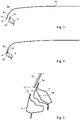
Fig. 2 schematically shows in cross section of the front windscreen, a driver side A-pillar and a co-driver side A-pillar of the motor vehicle ofFigure 1 in a situation prior to mounting the front windscreen to the A-pillars; -
Fig. 3 schematically shows in cross section a step of mounting the front windscreen to the A-pillars ofFigure 2 in which step the front windscreen is slightly bent open; -
Fig. 4 schematically shows in cross section the situation in which the front windscreen ofFigure 3 is mounted to the A-pillars; -
Fig. 5 schematically shows in cross section a detail of the front windscreen mounted to the driver side A-pillar and the driver side door in closed position; -
Figs. 6 and 7 schematically show in perspective an embodiment of a two part A-pillar trim of the motor vehicle according to the invention, in which inFigure 6 the A-pillar cover of the A-pillar trim is shown and inFigure 7 the A-pillar carrier of the A-pillar trim is shown; -
Fig. 8 schematically shows in side view the A-pillar carrier ofFigure 7 ; -
Fig. 9 schematically shows in side view a detail of the A-pillar carrier as shown inFigure 8 ; -
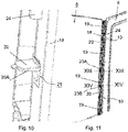
Fig. 10 schematically shows in perspective a detail of the A-pillar carrier as shown inFigure 9 ; -
Fig. 11 schematically shows in perspective shows the A-pillar carrier ofFigures 7 and 8 mounted to the driver side A-pillar; -
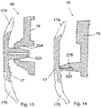
Fig. 12 schematically shows in cross section the A-pillar cover mounted to the A-pillar carrier ofFigure 11 ; -
Fig. 13 schematically shows a cross section of the A-pillar cover mounted to the A-pillar carrier at the position indicated by the line XIII-XIII ofFigure 11 ; and -
Fig. 14 schematically shows cross section of the A-pillar cover mounted to the A-pillar carrier at the position indicated by the line XIV-XIV ofFigure 11 . - In
Fig. 1 a motor vehicle according to the invention is schematically shown in perspective. In the shown embodiment the motor vehicle is aheavy goods vehicle 1 comprising adriver cabin 2 having adriver side 3 and aco-driver side 4 positioned at the opposite side of thedriver side 3. As is common in the field of motor vehicles, thedriver cabin 2 comprises adriver side A-pillar 5, a co-driver side A-pillar 6 (see e.g.Fig. 2 ), a driver side B-pillar 7 and a co-driver side B-pillar (not visible inFigure 1 ). - A
front windscreen 8 extends at an outside of thedriver side A-pillar 5 and at an outside of theco-driver side A-pillar 6. Thefront windscreen 8 has acentral windscreen section 8A,curved corners 8B and a straight windscreendriver side portion 8C and a straight windscreenco-driver side portion 8D as indicated inFigure 2 . - The
driver cabin 2 has adriver side door 9 hingeably mounted to the driver side of thedriver cabin 2. Thedriver side door 9 extends between thedriver side A-pillar 5 and the driver side B-pillar 7. Thedrive side door 9 has a leadingedge 10 facing thedriver side A-pillar 5 and atrailing edge 11 facing the driver side B-pillar 7. Analogously the co-driver side door is hingeably mounted to the co-driver side4 of thedriver cabin 2 and extends between theco-driver side A-pillar 6 and the co-driver side B-pillar. As thedriver side door 9 the co-drive side door has a leading edge 14 (seeFig. 2 ) facing theco-driver side A-pillar 6 and a trailing edge facing the co-driver side B-pillar. - As indicated in
Figure 1 thecentral windscreen section 8A covers an aperture between the driver side A-pillar 5 and the co-driver side A-pillar 6. The straight windscreendriver side portion 8C has arear edge 12 facing and spaced from the leadingedge 10 of the driver side door 9 (seeFig. 5 ). Analogously, the straight windscreenco-driver side portion 8D has a rear edge 14 (seeFig. 2 ) facing the leading edge of the co-driver side door. - A driver side gap 15 (see
Fig. 5 and12 ) is present between therear edge 12 of the straight windscreendriver side portion 8C and the leadingedge 10 of thedriver side door 9. The same applies to theco-driver side 4 of thedriver cabin 2, where a co-driver side gap is present between therear edge 14 of the straight windscreenco-driver side portion 8D and the leading edge of the co-driver side door. - According to the invention the
front windscreen 8 is glued in an overstressed mounted state to the driver side A-pillar 5 and the co-driver side A-pillar 6 as will be explained with reference toFigures 2 to 4 . As indicated inFigure 2 according to the invention afront windscreen 8 is used of which an outer width w at a specific height prior to mounting is smaller than a distance d between a most forwardinner edge 5A of the driver side A-pillar 5 and a most forwardinner edge 6A of the co-driver side A-pillar 6 at the same specific height. In particular, prior to mounting the outer width w of thefront windscreen 8 at a specific height is up to 10 mm smaller than a distance d between most forwardinner edge 5A of the driver side A-pillar 5 and the most forwardinner edge 6A of the co-driver side A-pillar 6 at the same height. - The
front windscreen 8 is mounted onto the A-pillars 5, 6 by bending thefront windscreen 8 open as indicated by the arrow inFigure 2 . In this manner the width of thefront windscreen 8 is enlarged such that it becomes larger than the distance d. Then thefront windscreen 8 is placed over the driver side A-pillar 5 and co-driver side A-pillar 6, on which previously glue has been applied, and the front windscreen is released such that it is in contact with the A-pillars, as indicated inFigure 4 for the driver side A-pillar 5. In this manner thefront windscreen 8 is mounted in an overstressed state to the A-pillars 5, 6. The described mounting of thefront windscreen 8 can for example be performed by mounting robots. - As indicated in
Figures 4 and 5 mounting thefront windscreen 8 is performed such that therear edge 12 of the straight windscreendriver side portion 8C is positioned on the outside of the driver side A-pillar 5 between the most forwardinner edge 5A of the driver side A-pillar 5 and anouter edge 5B of the driver side A-pillar 5. The same applies to theco-driver side 4 where therear edge 14 of the straight windscreenco-driver side portion 8D is positioned on the outside of the co-driver side A-pillar 6 between the most forwardinner edge 6A of the co-driver side A-pillar 6 and anouter edge 6B of the co-driver side A-pillar 6. - In the embodiment of the heavy goods vehicle as indicated in the Figures the length of the straight windscreen
driver side portion 8C and the length of the straight windscreenco-driver side portion 8D as seen in a usual driving direction of theheavy goods vehicle 1 is larger than 100 mm as a result of which aerodynamic drag is reduced. - In assembling the
driver side door 9 to thedriver cabin 2 thedriver side door 9 is positioned relative to the driver side B-pillar 7 in order to obtain a defined gap and flushness between the driver side door and the B-pillar 7 in order to obtain good aerodynamic properties at the interface between thedriver side door 9 and the driver side B-pillar 7. Due to e.g. manufacturing tolerances positioning thedriver side door 9 with regard to the driver side B-pillar 7 can result ingaps 15 at the driver side A-pillar 5 which varies from oneheavy goods vehicle 1 to the other. According to theinvention gaps 15 of varying dimensions can be closed and flushness between the straight windscreendriver side portion 8C and thedriver side door 9 can be realized by providing a driver side A-pillar trim 16 arranged for covering thedriver side gap 15 and for providing flushness between the straight windscreendriver side portion 8C and thedriver side door 9. At the co-driver side 4 a similar co-driver side A-pillar trim is arranged for covering the co-driver side gap and for providing flushness between the straight windscreen co-driver side portion and the co-driver side door. The construction of the A-pillar trim will be discussed below with regard to the driver sideA-pillar trim 16, however it will be understood that the description also holds for the co-driver side A-pillar trim. - According to the invention the
A-pillar trim 16 comprises an A-pillar carrier 18 (see e.g.Figure 7 ) to be attached to the A-pillar 5 and a separate A-pillar cover 17 (see e.g.Figure 6 ) to be attached to theA-pillar carrier 18. As indicated inFigures 8 and11 theA-pillar carrier 18 comprises at least fourslot holes 19 oriented in a usual driving direction of theheavy goods vehicle 1. TheA-pillar carrier 18 is provided with at least onestop plate 20, preferably twostop plates 20 are provided, which stopplates 20 are hingeably connected to theA-pillar carrier 18. This can for example be realized by injection moulding theA-pillar carrier 18, in which moulding process the stop plates are arranged to be hingeable along line-hinges. - As indicated in
Figure 11 theA-pillar carrier 18 is positioned on the driver side A-pillar 5 and by the virtue of the slot holes 19 is slid towards thedriver side door 9 until a trailingside 20A (seeFigure 10 ) of thestop plate 20 is in contact with the leadingedge 10 of thedriver side door 9 in closed position. In particular the vertical orientation of theA-pillar carrier 18 with regard to the driver side A-pillar 5 is determined by thesecond slot hole 19 seen from the top, although in other embodiments the topmost slot hole 19 can be used. In this manner theA-pillar carrier 18 is correctly positioned with regard to thedriver side door 9, and is attached to the driver side A-pillar 18 by means of e.g. screws or bolts passing through the slotted holes 19. Thestop plates 20 are then pushed back intoopenings 21 in theA-pillar carrier 18 so that they are not protruding. - After the
A-pillar carrier 18 is attached to the driver side A-pillar 5 theA-pillar cover 17 and theA-pillar carrier 18 are snap fitted together by means of first snap fit means 22 on theA-pillar cover 17 and second snap fit means 23 on theA-pillar carrier 18, which snap fit means 22, 23 cooperate with each other. Exemplary embodiments of such snap fit means 22A, 22B and 23A, 23B are indicated inFigures 13 and 14 , and different kinds of snap fit means 22A, 22B; 23A, 23B can be incorporated into anA-pillar trim 18 at different heights as indicated inFigure 11 . By snap fitting theA-pillar cover 17 to theA-pillar carrier 18 thegap 15 between therear edge 12 of the straight windscreendriver side portion 8C and the leadingedge 10 of thedriver side door 9 is closed as indicated inFigure 12 . - According to the invention flushness between the straight windscreen
driver side portion 8C and thedriver side door 9 is obtained in that theA-pillar cover 17 comprises of leading sealing 17A and a trailing sealing 17B as shown inFigures 12 to 14 . The trailing sealing 17B engages an inner side of the leadingedge 10 of thedriver side door 9, while the leading sealing 17A engages an outer side of therear edge 12 of the driver side straightwindscreen side portion 8C. AS indicated inFigure 6 a top of the leading sealing 17A and a top of the trailing sealing 17B are connected to each other by atop sealing 17C, which top sealing 17C in assembled states of thedriver cabin 2 engages a roof of thedriver cabin 2. Preferably, theA-pillar cover 17 comprises an A-pillar main body 17D and thesealings 17A-17C, wherein the A-pillar main body 17D and thesealings 17A-C are formed by a 2K-process. - Due to the contact condition of the trailing sealing 17B the
A-pillar cover 17 can be prone to rotations along the vertical axis as result of opening and closing movements of thedriver side door 9, which could result in wear and an unwanted open gap condition between the leading sealing 17A and the front windscreen. By providing theA-pillar carrier 18 withridges 24 which extend in vertical direction, whichridges 24 are provided on a side of theA-pillar carrier 18 directed towards thedriver side door 9 as shown inFigures 7, 9 and11 , theridges 24 engage the trailing sealing 17B of theA-pillar cover 17. In this manner rotation of theA-pillar cover 17 as a result of opening and closing movements of thedriver side door 9 can be avoided.
Claims (12)
- A motor vehicle, in particular a heavy goods vehicle, comprising a driver cabin having a driver side and a co-driver side, the driver cabin comprising:- a driver side A-pillar, a co-driver side A-pillar, a driver side B-pillar and a co-driver side B-pillar;- a front windscreen having a central windscreen section, curved corners and a straight windscreen driver side portion and a straight windscreen co-driver side portion;- a driver side door hingeably mounted to the driver side of the driver cabin and extending between the driver side A-pillar and the driver side B-pillar, the drive side door having a leading edge facing the driver side A-pillar and a trailing edge facing the driver side B-pillar, and a co-driver side door hingeably mounted to the co-driver side of the driver cabin and extending between the co-driver side A-pillar and the co-driver side B-pillar, the co-drive side door having a leading edge facing the co-driver side A-pillar and a trailing edge facing the co-driver side B-pillar;- the front windscreen extending at an outside of the driver side A-pillar and at an outside of the co-driver side A-pillar, the central windscreen section covering an aperture between the driver side A-pillar and the co-driver side A-pillar, the straight windscreen driver side portion having a rear edge facing and spaced from the leading edge of the driver side door, the straight windscreen co-driver side portion having a rear edge facing the leading edge of the co-driver side door, a driver side gap being present between the rear edge of the straight windscreen driver side portion and the leading edge of the driver side door, and a co-driver side gap being present between the rear edge of the straight windscreen co-driver side portion and the leading edge of the co-driver side door;characterized in that the front windscreen is glued in an overstressed mounted state to the driver side A-pillar and the co-driver side A-pillar, the overstressed mounted state being obtained by using a front windscreen of which an outer width at a specific height prior to mounting is smaller than a distance between a most forward inner edge of the driver side A-pillar and a most forward inner edge of the co-driver side A-pillar at the same height, by bending the front windscreen open and placing it over and gluing it to the driver side A-pillar and co-driver side A-pillar,the rear edge of the straight windscreen driver side portion being positioned on the outside of the driver side A-pillar between the most forward inner edge of the driver side A-pillar and an outer edge of the driver side A-pillar, and the rear edge of the straight windscreen co-driver side portion being positioned on the outside of the co-driver side A-pillar between the most forward inner edge of the co-driver side A-pillar and an outer edge of the co-driver side A-pillar; andin that the motor vehicle comprises a driver side A-pillar trim arranged for covering the driver side gap and for providing flushness between the straight windscreen driver side portion and the driver side door and a co-driver side A-pillar trim arranged for covering the co-driver side gap and for providing flushness between the straight windscreen co-driver side portion and the co-driver side door.
- A motor vehicle according to claim 1, wherein prior to mounting the outer width of the front windscreen at a specific height is up to 10 mm smaller than a distance between most forward inner edge of the driver side A-pillar and the most forward inner edge of the co-driver side A-pillar at the same height.
- A motor vehicle according to claim 1 or 2, wherein the length of the straight windscreen driver side portion and the length of the straight windscreen co-driver side portion as seen in a usual driving direction of the motor vehicle is larger than 100 mm.
- A motor vehicle according to claim 1, 2 or 3, wherein each A-pillar trim comprises an A-pillar carrier attached to the respective A-pillar and a separate A-pillar cover attached to the A-pillar carrier.
- A motor vehicle according to claim 4, wherein the A-pillar carrier comprises at least four slot holes oriented in a usual driving direction of the motor vehicle and at least one stop plate hingeably connected to the A-pillar carrier, a trailing side of the stop plate being in line with the leading edge of the respective door in a closed position.
- A motor vehicle according to claim 5, wherein the A-pillar carrier has two stop plates hingeably connected to the A-pillar carrier, the trailing side of each of the stop plates being in line with the leading edge of the respective door in the closed position.
- A motor vehicle according to claim 5 or 6, wherein the vertical orientation of the A-pillar carrier with regard to the respective A-pillar is determined by the second slot hole seen from the top.
- A motor vehicle according to any one of the claims 4 to 7, wherein the A-pillar cover and the A-pillar carrier are snap fitted together by means of first snap fit means on the A-pillar cover and second snap fit means on the A-pillar carrier cooperating with the first snap fit means.
- A motor vehicle according to any one of the claims 4 to 8, wherein the A-pillar cover comprises of leading sealing and a trailing sealing, the trailing sealing engaging an inner side of the leading edge of the respective door, the leading sealing engaging an outer side of the rear edge of the respective straight windscreen side portion.
- A motor vehicle according to claim 9, wherein a top of the leading sealing and a top of the trailing sealing are connected to each other by a top sealing, the top sealing engaging a roof of the driver cabin.
- A motor vehicle according to claim 9 or 10, wherein the A-pillar cover comprises an A-pillar main body and the leading sealing and the trailing sealing, the A-pillar main body and the sealings formed by a 2K-process.
- A motor vehicle according to any one of the claims 4 to 11, wherein the A-pillar carrier comprises ridges extending in vertical direction, the ridges being provided on a side of the A-pillar carrier directed towards the respective door, the ridges engaging the trailing sealing of the A-pillar cover.
Applications Claiming Priority (1)
| Application Number | Priority Date | Filing Date | Title |
|---|---|---|---|
| NL2027768A NL2027768B1 (en) | 2021-03-18 | 2021-03-18 | A motor vehicle. |
Publications (3)
| Publication Number | Publication Date |
|---|---|
| EP4059749A1 true EP4059749A1 (en) | 2022-09-21 |
| EP4059749B1 EP4059749B1 (en) | 2024-01-03 |
| EP4059749C0 EP4059749C0 (en) | 2024-01-03 |
Family
ID=76159927
Family Applications (1)
| Application Number | Title | Priority Date | Filing Date |
|---|---|---|---|
| EP22162821.7A Active EP4059749B1 (en) | 2021-03-18 | 2022-03-17 | A motor vehicle |
Country Status (2)
| Country | Link |
|---|---|
| EP (1) | EP4059749B1 (en) |
| NL (1) | NL2027768B1 (en) |
Citations (5)
| Publication number | Priority date | Publication date | Assignee | Title |
|---|---|---|---|---|
| DE2659538B1 (en) * | 1976-12-30 | 1978-03-30 | Hamburger Hochbahn Ag | Omnibus windscreen |
| JPS6099716A (en) * | 1983-11-05 | 1985-06-03 | Nissan Motor Co Ltd | Window panel fixing method |
| DE3935611A1 (en) * | 1988-11-02 | 1990-05-03 | Volkswagen Ag | TAILGATE FOR A MOTOR VEHICLE AND METHOD FOR THEIR PRODUCTION |
| EP1152940B1 (en) | 1999-02-23 | 2004-02-11 | International Truck Intellectual Property Company, LLC. | Truck aerodynamic a-pillar design |
| FR2947498A1 (en) * | 2009-07-03 | 2011-01-07 | Peugeot Citroen Automobiles Sa | Cover for window post of windscreen of motor vehicle, has gutter permitting discharge of swept water on windscreen through windscreen wiper, and exterior skin in flush contact with windscreen |
-
2021
- 2021-03-18 NL NL2027768A patent/NL2027768B1/en not_active IP Right Cessation
-
2022
- 2022-03-17 EP EP22162821.7A patent/EP4059749B1/en active Active
Patent Citations (5)
| Publication number | Priority date | Publication date | Assignee | Title |
|---|---|---|---|---|
| DE2659538B1 (en) * | 1976-12-30 | 1978-03-30 | Hamburger Hochbahn Ag | Omnibus windscreen |
| JPS6099716A (en) * | 1983-11-05 | 1985-06-03 | Nissan Motor Co Ltd | Window panel fixing method |
| DE3935611A1 (en) * | 1988-11-02 | 1990-05-03 | Volkswagen Ag | TAILGATE FOR A MOTOR VEHICLE AND METHOD FOR THEIR PRODUCTION |
| EP1152940B1 (en) | 1999-02-23 | 2004-02-11 | International Truck Intellectual Property Company, LLC. | Truck aerodynamic a-pillar design |
| FR2947498A1 (en) * | 2009-07-03 | 2011-01-07 | Peugeot Citroen Automobiles Sa | Cover for window post of windscreen of motor vehicle, has gutter permitting discharge of swept water on windscreen through windscreen wiper, and exterior skin in flush contact with windscreen |
Also Published As
| Publication number | Publication date |
|---|---|
| EP4059749B1 (en) | 2024-01-03 |
| NL2027768B1 (en) | 2022-09-29 |
| EP4059749C0 (en) | 2024-01-03 |
Similar Documents
| Publication | Publication Date | Title |
|---|---|---|
| CN108263486B (en) | Loose layered assembly component and vehicle front end assembling method | |
| US7845713B2 (en) | Pillar structure of automobile | |
| US9114693B2 (en) | Daylight opening system | |
| US8419099B2 (en) | Vehicle body structure | |
| CN108146364B (en) | Vehicle body structure and decorative member | |
| JP6889567B2 (en) | Exterior structure of vehicle doors | |
| CN107444080B (en) | Vehicle body structure | |
| CN115052770B (en) | Tail door of vehicle | |
| EP4059749B1 (en) | A motor vehicle | |
| US12005843B2 (en) | Decorative strip assembly for a motor vehicle door | |
| US10266127B2 (en) | Retention features for vehicular gloveboxes | |
| US7798686B2 (en) | Fender tab and locating cradle | |
| CN120882624A (en) | Vehicle window seal assembly | |
| CN115916634A (en) | Vehicle with spoiler and method for fitting spoiler on vehicle | |
| US6022065A (en) | Vehicle window, especially for motorized vehicles, and method for mounting such a vehicle window | |
| US12337664B2 (en) | Seal retention clip for vehicle window assembly | |
| CN222682366U (en) | Bumper decoration assembly, front bumper assembly and vehicle | |
| JP4911553B2 (en) | Split cowl panel | |
| US20260125018A1 (en) | Fascia integrated ags | |
| JP2013159192A (en) | Rocker molding mounting structure of automobile | |
| CN223100424U (en) | Armrest assembly mounted on vehicle door, vehicle door assembly and vehicle | |
| CN220220621U (en) | Back door decoration assembly, back door, white car body and car | |
| CN216886546U (en) | Radar capable of shielding gap, mounting structure thereof and vehicle | |
| CN117818501A (en) | Decorative parts for vehicle rear parts and vehicle rear structure | |
| JPH0732195Y2 (en) | Locking tool for automobile windshield molding |
Legal Events
| Date | Code | Title | Description |
|---|---|---|---|
| PUAI | Public reference made under article 153(3) epc to a published international application that has entered the european phase |
Free format text: ORIGINAL CODE: 0009012 |
|
| STAA | Information on the status of an ep patent application or granted ep patent |
Free format text: STATUS: THE APPLICATION HAS BEEN PUBLISHED |
|
| AK | Designated contracting states |
Kind code of ref document: A1 Designated state(s): AL AT BE BG CH CY CZ DE DK EE ES FI FR GB GR HR HU IE IS IT LI LT LU LV MC MK MT NL NO PL PT RO RS SE SI SK SM TR |
|
| STAA | Information on the status of an ep patent application or granted ep patent |
Free format text: STATUS: REQUEST FOR EXAMINATION WAS MADE |
|
| 17P | Request for examination filed |
Effective date: 20230131 |
|
| RBV | Designated contracting states (corrected) |
Designated state(s): AL AT BE BG CH CY CZ DE DK EE ES FI FR GB GR HR HU IE IS IT LI LT LU LV MC MK MT NL NO PL PT RO RS SE SI SK SM TR |
|
| P01 | Opt-out of the competence of the unified patent court (upc) registered |
Effective date: 20230505 |
|
| GRAP | Despatch of communication of intention to grant a patent |
Free format text: ORIGINAL CODE: EPIDOSNIGR1 |
|
| STAA | Information on the status of an ep patent application or granted ep patent |
Free format text: STATUS: GRANT OF PATENT IS INTENDED |
|
| INTG | Intention to grant announced |
Effective date: 20230727 |
|
| GRAS | Grant fee paid |
Free format text: ORIGINAL CODE: EPIDOSNIGR3 |
|
| GRAA | (expected) grant |
Free format text: ORIGINAL CODE: 0009210 |
|
| STAA | Information on the status of an ep patent application or granted ep patent |
Free format text: STATUS: THE PATENT HAS BEEN GRANTED |
|
| AK | Designated contracting states |
Kind code of ref document: B1 Designated state(s): AL AT BE BG CH CY CZ DE DK EE ES FI FR GB GR HR HU IE IS IT LI LT LU LV MC MK MT NL NO PL PT RO RS SE SI SK SM TR |
|
| REG | Reference to a national code |
Ref country code: GB Ref legal event code: FG4D |
|
| REG | Reference to a national code |
Ref country code: DE Ref legal event code: R096 Ref document number: 602022001505 Country of ref document: DE |
|
| REG | Reference to a national code |
Ref country code: CH Ref legal event code: EP |
|
| REG | Reference to a national code |
Ref country code: IE Ref legal event code: FG4D |
|
| U01 | Request for unitary effect filed |
Effective date: 20240126 |
|
| U07 | Unitary effect registered |
Designated state(s): AT BE BG DE DK EE FI FR IT LT LU LV MT NL PT SE SI Effective date: 20240205 |
|
| P04 | Withdrawal of opt-out of the competence of the unified patent court (upc) registered |
Effective date: 20240131 |
|
| U20 | Renewal fee for the european patent with unitary effect paid |
Year of fee payment: 3 Effective date: 20240220 |
|
| PG25 | Lapsed in a contracting state [announced via postgrant information from national office to epo] |
Ref country code: ES Free format text: LAPSE BECAUSE OF FAILURE TO SUBMIT A TRANSLATION OF THE DESCRIPTION OR TO PAY THE FEE WITHIN THE PRESCRIBED TIME-LIMIT Effective date: 20240103 |
|
| PG25 | Lapsed in a contracting state [announced via postgrant information from national office to epo] |
Ref country code: ES Free format text: LAPSE BECAUSE OF FAILURE TO SUBMIT A TRANSLATION OF THE DESCRIPTION OR TO PAY THE FEE WITHIN THE PRESCRIBED TIME-LIMIT Effective date: 20240103 |
|
| PG25 | Lapsed in a contracting state [announced via postgrant information from national office to epo] |
Ref country code: IS Free format text: LAPSE BECAUSE OF FAILURE TO SUBMIT A TRANSLATION OF THE DESCRIPTION OR TO PAY THE FEE WITHIN THE PRESCRIBED TIME-LIMIT Effective date: 20240503 |
|
| PG25 | Lapsed in a contracting state [announced via postgrant information from national office to epo] |
Ref country code: GR Free format text: LAPSE BECAUSE OF FAILURE TO SUBMIT A TRANSLATION OF THE DESCRIPTION OR TO PAY THE FEE WITHIN THE PRESCRIBED TIME-LIMIT Effective date: 20240404 |
|
| PG25 | Lapsed in a contracting state [announced via postgrant information from national office to epo] |
Ref country code: HR Free format text: LAPSE BECAUSE OF FAILURE TO SUBMIT A TRANSLATION OF THE DESCRIPTION OR TO PAY THE FEE WITHIN THE PRESCRIBED TIME-LIMIT Effective date: 20240103 Ref country code: RS Free format text: LAPSE BECAUSE OF FAILURE TO SUBMIT A TRANSLATION OF THE DESCRIPTION OR TO PAY THE FEE WITHIN THE PRESCRIBED TIME-LIMIT Effective date: 20240403 |
|
| PG25 | Lapsed in a contracting state [announced via postgrant information from national office to epo] |
Ref country code: CZ Free format text: LAPSE BECAUSE OF FAILURE TO SUBMIT A TRANSLATION OF THE DESCRIPTION OR TO PAY THE FEE WITHIN THE PRESCRIBED TIME-LIMIT Effective date: 20240103 |
|
| PG25 | Lapsed in a contracting state [announced via postgrant information from national office to epo] |
Ref country code: RS Free format text: LAPSE BECAUSE OF FAILURE TO SUBMIT A TRANSLATION OF THE DESCRIPTION OR TO PAY THE FEE WITHIN THE PRESCRIBED TIME-LIMIT Effective date: 20240403 Ref country code: NO Free format text: LAPSE BECAUSE OF FAILURE TO SUBMIT A TRANSLATION OF THE DESCRIPTION OR TO PAY THE FEE WITHIN THE PRESCRIBED TIME-LIMIT Effective date: 20240403 Ref country code: IS Free format text: LAPSE BECAUSE OF FAILURE TO SUBMIT A TRANSLATION OF THE DESCRIPTION OR TO PAY THE FEE WITHIN THE PRESCRIBED TIME-LIMIT Effective date: 20240503 Ref country code: HR Free format text: LAPSE BECAUSE OF FAILURE TO SUBMIT A TRANSLATION OF THE DESCRIPTION OR TO PAY THE FEE WITHIN THE PRESCRIBED TIME-LIMIT Effective date: 20240103 Ref country code: GR Free format text: LAPSE BECAUSE OF FAILURE TO SUBMIT A TRANSLATION OF THE DESCRIPTION OR TO PAY THE FEE WITHIN THE PRESCRIBED TIME-LIMIT Effective date: 20240404 Ref country code: CZ Free format text: LAPSE BECAUSE OF FAILURE TO SUBMIT A TRANSLATION OF THE DESCRIPTION OR TO PAY THE FEE WITHIN THE PRESCRIBED TIME-LIMIT Effective date: 20240103 |
|
| PG25 | Lapsed in a contracting state [announced via postgrant information from national office to epo] |
Ref country code: PL Free format text: LAPSE BECAUSE OF FAILURE TO SUBMIT A TRANSLATION OF THE DESCRIPTION OR TO PAY THE FEE WITHIN THE PRESCRIBED TIME-LIMIT Effective date: 20240103 |
|
| PG25 | Lapsed in a contracting state [announced via postgrant information from national office to epo] |
Ref country code: PL Free format text: LAPSE BECAUSE OF FAILURE TO SUBMIT A TRANSLATION OF THE DESCRIPTION OR TO PAY THE FEE WITHIN THE PRESCRIBED TIME-LIMIT Effective date: 20240103 |
|
| REG | Reference to a national code |
Ref country code: DE Ref legal event code: R097 Ref document number: 602022001505 Country of ref document: DE |
|
| PG25 | Lapsed in a contracting state [announced via postgrant information from national office to epo] |
Ref country code: SM Free format text: LAPSE BECAUSE OF FAILURE TO SUBMIT A TRANSLATION OF THE DESCRIPTION OR TO PAY THE FEE WITHIN THE PRESCRIBED TIME-LIMIT Effective date: 20240103 |
|
| PG25 | Lapsed in a contracting state [announced via postgrant information from national office to epo] |
Ref country code: SK Free format text: LAPSE BECAUSE OF FAILURE TO SUBMIT A TRANSLATION OF THE DESCRIPTION OR TO PAY THE FEE WITHIN THE PRESCRIBED TIME-LIMIT Effective date: 20240103 |
|
| PG25 | Lapsed in a contracting state [announced via postgrant information from national office to epo] |
Ref country code: SM Free format text: LAPSE BECAUSE OF FAILURE TO SUBMIT A TRANSLATION OF THE DESCRIPTION OR TO PAY THE FEE WITHIN THE PRESCRIBED TIME-LIMIT Effective date: 20240103 Ref country code: SK Free format text: LAPSE BECAUSE OF FAILURE TO SUBMIT A TRANSLATION OF THE DESCRIPTION OR TO PAY THE FEE WITHIN THE PRESCRIBED TIME-LIMIT Effective date: 20240103 Ref country code: RO Free format text: LAPSE BECAUSE OF FAILURE TO SUBMIT A TRANSLATION OF THE DESCRIPTION OR TO PAY THE FEE WITHIN THE PRESCRIBED TIME-LIMIT Effective date: 20240103 |
|
| PLBE | No opposition filed within time limit |
Free format text: ORIGINAL CODE: 0009261 |
|
| STAA | Information on the status of an ep patent application or granted ep patent |
Free format text: STATUS: NO OPPOSITION FILED WITHIN TIME LIMIT |
|
| PG25 | Lapsed in a contracting state [announced via postgrant information from national office to epo] |
Ref country code: MC Free format text: LAPSE BECAUSE OF FAILURE TO SUBMIT A TRANSLATION OF THE DESCRIPTION OR TO PAY THE FEE WITHIN THE PRESCRIBED TIME-LIMIT Effective date: 20240103 |
|
| PG25 | Lapsed in a contracting state [announced via postgrant information from national office to epo] |
Ref country code: MC Free format text: LAPSE BECAUSE OF FAILURE TO SUBMIT A TRANSLATION OF THE DESCRIPTION OR TO PAY THE FEE WITHIN THE PRESCRIBED TIME-LIMIT Effective date: 20240103 |
|
| 26N | No opposition filed |
Effective date: 20241007 |
|
| P05 | Withdrawal of opt-out of the competence of the unified patent court (upc) changed |
Free format text: CASE NUMBER: APP_5625/2024 Effective date: 20240205 |
|
| PG25 | Lapsed in a contracting state [announced via postgrant information from national office to epo] |
Ref country code: IE Free format text: LAPSE BECAUSE OF NON-PAYMENT OF DUE FEES Effective date: 20240317 |
|
| PG25 | Lapsed in a contracting state [announced via postgrant information from national office to epo] |
Ref country code: IE Free format text: LAPSE BECAUSE OF NON-PAYMENT OF DUE FEES Effective date: 20240317 |
|
| U20 | Renewal fee for the european patent with unitary effect paid |
Year of fee payment: 4 Effective date: 20250211 |
|
| PG25 | Lapsed in a contracting state [announced via postgrant information from national office to epo] |
Ref country code: CY Free format text: LAPSE BECAUSE OF FAILURE TO SUBMIT A TRANSLATION OF THE DESCRIPTION OR TO PAY THE FEE WITHIN THE PRESCRIBED TIME-LIMIT; INVALID AB INITIO Effective date: 20220317 |
|
| REG | Reference to a national code |
Ref country code: CH Ref legal event code: H13 Free format text: ST27 STATUS EVENT CODE: U-0-0-H10-H13 (AS PROVIDED BY THE NATIONAL OFFICE) Effective date: 20251023 |
|
| PG25 | Lapsed in a contracting state [announced via postgrant information from national office to epo] |
Ref country code: TR Free format text: LAPSE BECAUSE OF FAILURE TO SUBMIT A TRANSLATION OF THE DESCRIPTION OR TO PAY THE FEE WITHIN THE PRESCRIBED TIME-LIMIT Effective date: 20240103 |
|
| PG25 | Lapsed in a contracting state [announced via postgrant information from national office to epo] |
Ref country code: CH Free format text: LAPSE BECAUSE OF NON-PAYMENT OF DUE FEES Effective date: 20250331 |
|
| PGFP | Annual fee paid to national office [announced via postgrant information from national office to epo] |
Ref country code: GB Payment date: 20260324 Year of fee payment: 5 |
|
| U20 | Renewal fee for the european patent with unitary effect paid |
Year of fee payment: 5 Effective date: 20260326 |
|
| PG25 | Lapsed in a contracting state [announced via postgrant information from national office to epo] |
Ref country code: CH Free format text: THE PATENT HAS BEEN ANNULLED BY A DECISION OF A NATIONAL AUTHORITY Effective date: 20250331 |